Chapter 7: Applications of Integrationrichardt/1S3/ch7.pdf · Chapter 7: Applications of...
23
Chapter 7: Applications of Integration Course 1S3, 2006–07 May 11, 2007 These are just summaries of the lecture notes, and few details are included. Most of what we include here is to be found in more detail in Anton. 7.1 Remark. The aim here is to illustrate that integrals (definite integrals) have applications to practical things. Quite a few concepts in scientific theories are explained in terms of integrals, but to go into them would require a knowledge of the necessary background. Some of the material that was covered in this chapter in previous years (areas, arc length, volumes of revolution) were covered in 1S1 this year. They are relegated to the appendix. We will consider a number of applications — fluid pressure, work, and centre of mass. 7.2 Fluid Pressure. We now explain an application of integration to fluid pressure. First we need some idea of what a fluid is and what we mean by pressure. Then a little about how to work with it. Roughly a fluid is a liquid or a gas. They have the property that they adapt their shape to the shape of any container they are in. The fluid will then exert a force on the wall of the container. In the case of a gas (like the air in a tyre) the pressure comes from the internal energy of the gas (the molecules of gas will be moving around and causing the pressure by bouncing off the walls). In the case of a fluid, we are thinking of gravity making the fluid settle to the bottom of the container and we are not considering increased pressure that might come from a pump or other mechanism. We will deal with the fluid case. To avoid complications we will assume we have a uniform incompressible fluid (say water or oil, but not a mixture where there could be layers of different types). The pressure exerted by the liquid is force per unit area. Pressure = Force Area To get the pressure at a point (say a point on the wall of the container) we should measure the force on a tiny section of the wall and divide by the area of that tiny section. In this way we get the pressure at that point and not the average over a bigger area. The key properties are that the pressure depends only on the depth (distance down from the free surface of the liquid) and does not depend on direction. Even if the link to the surface is not direct (for example a water tap linked to a tank upstairs by a pipe that goes under the floor), the pressure still depends only on the depth and not on the volume of liquid above the point. 1
Transcript of Chapter 7: Applications of Integrationrichardt/1S3/ch7.pdf · Chapter 7: Applications of...

Chapter 7: Applications of Integration
Course 1S3, 2006–07
May 11, 2007
These are just summaries of the lecture notes, and few details are included. Most of what weinclude here is to be found in more detail in Anton.
7.1 Remark. The aim here is to illustrate that integrals (definite integrals) have applications topractical things. Quite a few concepts in scientific theories are explained in terms of integrals,but to go into them would require a knowledge of the necessary background.
Some of the material that was covered in this chapter in previous years (areas, arc length,volumes of revolution) were covered in 1S1 this year. They are relegated to the appendix.
We will consider a number of applications — fluid pressure, work, and centre of mass.
7.2 Fluid Pressure. We now explain an application of integration to fluid pressure. First weneed some idea of what a fluid is and what we mean by pressure. Then a little about how to workwith it.
Roughly a fluid is a liquid or a gas. They have the property that they adapt their shape to theshape of any container they are in. The fluid will then exert a force on the wall of the container.In the case of a gas (like the air in a tyre) the pressure comes from the internal energy of thegas (the molecules of gas will be moving around and causing the pressure by bouncing off thewalls). In the case of a fluid, we are thinking of gravity making the fluid settle to the bottomof the container and we are not considering increased pressure that might come from a pump orother mechanism.
We will deal with the fluid case. To avoid complications we will assume we have a uniformincompressible fluid (say water or oil, but not a mixture where there could be layers of differenttypes). The pressure exerted by the liquid is force per unit area.
Pressure =ForceArea
To get the pressure at a point (say a point on the wall of the container) we should measure theforce on a tiny section of the wall and divide by the area of that tiny section. In this way we getthe pressure at that point and not the average over a bigger area.
The key properties are that the pressure depends only on the depth (distance down from thefree surface of the liquid) and does not depend on direction. Even if the link to the surface is notdirect (for example a water tap linked to a tank upstairs by a pipe that goes under the floor), thepressure still depends only on the depth and not on the volume of liquid above the point.
1

2 1S3 2006–07 R. Timoney
We can work this out in terms of the strength of gravity (the acceleration due to gravity gif you like) and the density of the liquid. Density means mass per unit volume and we couldperhaps denote the value of this for our liquid by δ. However it is the gravitational force thatarises from the liquid that really counts for the force and this will be δg in units of Force/volume(weight force per unit volume). We call this quantity ρ and refer to it as the weight density of theliquid. The assumption that this is constant throughout the liquid translated into the fact that thepressure at depth h down from the free surface of the liquid is
Pressure = P = ρh
This is the force per unit area caused by the pressure of the liquid acting on a wall of the containerat a given depth h.
Now we consider a whole section of the wall of the container and try to figure out the totalforce on that (caused by the liquid). We cannot just multiply the pressure P by the area of thewall because the pressure varies with depth.
We think of a scenario as pictured here, where we have a vertical wall (that makes thingssimpler). The wall may be far below the surface of the liquid, or it may start at the surface. (Anybits of the wall that are not submerged are not going to matter as there will be no pressure onthose bits.)
tank
Surface
h
w(h)
a
b
wall of
To figure out the total pressure, we look at a specific depths h, or to avoid having zero area,we consider the part of the wall between depths h and h + dh. Then we work out the force onthat strip (constant depth h and so constant pressure P = ρh at that depth) to get
Force = P × area = ρh× area
To find the area of that horizontal strip, we treat it as a rectangle of total width w = w(h) anddepth dh. So
(area between depths h and h + dh) = w(h) dh

Chapter 7 — Applications of Integration 3
Notice that this width w(h) could vary as the depth changes, depending on the shape of the wall.We get
(Force on strip between depths h and h + dh) = ρhw(h) dh
and we add these up to get
Total pressure force =
∫ b
h=a
ρhw(h) dh
To review all the notation, h = the depth under the surface of the liquid. We are assumingthe liquid has uniform weight density ρ, the wall is vertical, the top of the wall is at depth h = a,the bottom at depth h = b and the width of the wall at depth h is w(h).
7.3 Example. The (vertical) end wall of a trough is in the form of an isosceles triangle with onethe point down. The top of the wall measures 4 units wide and the depth is 6 units. Find thepressure force on the wall caused by the liquid in the trough when the trough is just full to thebrim. (Your answer will be in terms of ρ the weight density of the liquid, which we assume to beuniform.)Solution: Here is a picture of the situation
with a cross section drawn at depth h (between h and h + dh. We need a formula for the widthw(h) at depth h and we can get this by using similar triangles. The ratio of the width to depthof the whole triangle is 4/6 and that will be the same for the lower triangle. The lower one hasdepth 6− h and so
4
6=
w(h)
6− h⇒ w(h) =
2
3(6− h)
The formula gives
Pressure force =
∫ 6
0
ρhw(h) dh =
∫ 6
0
2ρ
3h(6− h) dh =
∫ 6
0
2ρ
3(6h− h2) dh
and this works out . . . as 24ρ.

4 1S3 2006–07 R. Timoney
7.4 Work. Work is a technical term, with a precise meaning.First, consider a constant force acting on an object (we think of a particle or object concen-
trated at a point to avoid complications). Say the particle moves from one position to another.Then there is a dot product formula (using vectors) for the work done by the force on the object.
Let’s explain this from the beginning. We’re thinking in space (3 dimensions) for now, as thisis realistic. (Later we will make calculations in only one dimension as this is really all we knowenough to cope with for now.) A force is represented by a vector (think of an arrow in space)because it has a direction and a magnitude (or strength). Say the force is given by F (or ~F if youprefer a different notation for a vector). We won’t worry about the units, but we should assumewe are using a consistent set of units.
We can represent positions of points in space by coordinates (x, y, z) with respect to 3 (pre-selected and fixed) perpendicular axes meeting at a chosen origin. Or we can use the so-calledposition vector with components x, y and z in the directions of the 3 axes. So the position vectorof a point p = (x, y, z) is the vector p = xi + yj + zk where i is the unit vector in the directionof the x-axis, j is the unit vector in the direction of the y-axis, and k is the unit vector in thedirection of the z-axis. Once we get used to the idea that the same data is needed to specify apoint as is needed to specify a vector (3 numbers x, y and z which we may regard as coordinatesof the point or components of the vector) we realise quite quickly that it is convenient to switchpoints for their position vectors when it suits us.
Now if a particle moves form position p to position q, then its displacement is the vectorrepresented by the arrow from where it started p to where it ended q. In vector algebra thisdisplacement is the vector q− p, as you can work out from a picture like this:
This sort of manipulation of vectors should be familiar from 1S2.

Chapter 7 — Applications of Integration 5
The definition of the work done by a constant force F on a particle is given by the dot product(sometimes called the scalar product)
Work = Force · Displacement
orWork = F · (q− p)
if p is the starting position and q the ending position.Maybe it is no harm to recall a few little things about dot products. If a = a1i + a2j + a3k
and b = b1i + b2j + b3k are two vectors we can work out their dot product easily from
a · b = a1b1 + a2b2 + a3b3
(multiply the matching components and add up the answers so that the result is a scalar). Youcan also describe the number in a geometrical way, if you think in terms of the angle θ betweenthe two vectors:
a · b = ‖a‖‖b‖ cos θ
(where ‖a‖ means the length or magnitude of the vector a, which is given in components by‖a‖ =
√a2
1 + a22 + a2
3, and of course ‖b‖ is the length of b).Maybe a better notation is to use ∆p for the change in position, and then we get the formula
Work = Force · Displacement = F ·∆p
That is for a constant force. Suppose now that the force is changing as the particle moves. Sothe force is perhaps a function F(t) of time t (measured say in seconds from some starting time)and the particle has position p(t) at time t. In order to be able to plausibly use the formula fora constant force, what we do is think of dividing the elapsed time into really tiny time intervalsfrom t to d+dt. If dt is really small (think of it as infinitesimal) then the force should be more orless constant F(t) during that short time and the work done by the force in that short time shouldbe
Work = Force · Displacement = F(t) · (p(t + dt)− p(t))
We will writedp = p(t + dt)− p(t)
and the work done over the short interval as
Work = F(t) · dp
We then have to add up all the little bits of work to get the total work done. If the start-ing time is t = t0 and the ending time is t = t1 we get an integral (rather than a sum)
Work =
∫ t=t1
t=t0
F(t) · dp

6 1S3 2006–07 R. Timoney
This is an official definition, more or less 100% accurately stated, but it brings up a kind of in-tegral that we will not deal with until next years course. So we will only look at a rather specialcase, where the motion takes place along a single axis (the x-axis) and the force is also one di-mensional. That means that the force vector can only point right (in the positive direction) or left(negative direction) and is given by a number with a plus or minus sign. So we don’t really havevectors any more, as the position is given by a single coordinate x.
We will further simplify things and suppose that the force depends only on the position x,so that the force is F (x). Now the formula can be simplified because we can do the integralin the x variable (by substitution, or change of variable, from time t). The formula becomes
Work =
∫ x=x1
x=x0
F(x) · dx
for the work done by the force F (x) on the particle when the particle moves from starting placex = x0 to ending place x = x1.
Hooks Law. There is a realistic situation where a force F (x) of this kind does arise in prac-tice. Suppose the force is provided by a spring attached at one end to the particle and anchored atthe opposite end. We suppose the whole business is in one dimension so that the particle can onlymove back and forth along the x-axis and the spring is anchored somewhere on the axis. Hookslaw says that the force exerted by a spring is proportional to the amount the spring is compressedor expanded from its natural rest length. (This law is good provided you don’t stretch or squeezethe spring too far — if you do that it would eventually get distorted and not go back to its originalshape.)
To make life easy, say the spring is anchored somewhere to the left of the origin and the restlength of the print leaves the free end at the origin x = 0. Then the position x of the end tells youjust how much the spring is expanded (if x > 0) or compressed (if x < 0). Hooks Law says thenthere is a constant κ (called the spring constant) so that the force exerted by the spring when theend is at x is
F (x) = −κx
Here κ > 0 and you should be able to work out that the spring will be pulling the particleback to the left when x > 0. That is the reason for the minus sign, so that F (x) < 0 when x > 0(and F (x) > 0 when x < 0 because the spring will be pushing to the right when x < 0, meaningthat the spring is compressed).
For this example, if we suppose the particle moved from the position where x = 0.5 to the

Chapter 7 — Applications of Integration 7
position where x = 1, the work done by the spring on the particle would be
Work =
∫ 1
0.5
F (x) dx
=
∫ 1
0.5
−κx dx
=[−κ
2x2]1
0.5
= −κ
2−(−κ
2(0.5)2
)= −3
8κ
Note first that we would need to know the spring constant κ to get the actual value here.Second, note that it is perfectly possible for an amount of work to be negative (as it is here). Itmakes sense because the spring would be pulling in the opposite direction to the motion (as thespring is extended when x > 0) and so the particle is moving against the force.
You might ask how this could happen? Well, there are at least tow possible reasons. One isthat there is another force we have not mentioned (doing a positive amount of work against thespring). Another is that the particle could have an initial momentum, and, even though sloweddown by the spring, could still move against the spring. In fact, you could be looking at anoscillating thing, where the particle is oscillating back and forth past the equilibrium position atx = 0. If we just look at a part of the motion, we could be in the situation above.
It would also make sense to as for the work done if the particle moved from x = 1 to x = 0.5.This would be
Work =
∫ 0.5
1
F (x) dx
=
∫ 0.5
1
−κx dx
=[−κ
2x2]0.5
1
= −κ
2(0.5)2 −
(−κ
2
)=
3
8κ
7.5 Centres of mass. For some purposes the position of a solid object is described adequatelyby a single point, the centre of mass, and the object can be treated as a point mass at that point.For example, if considering gravity caused by the sun, we may treat the sun as a point massconcentrated at its centre. The gravitational force depends on the mass of the sun and the distanceto the centre of mass. The same is true of the moon or the earth, but this is not adequate if wewant to think about the rotation of any of these around their centres of mass.
If we look at a more mundane solid object like a golf ball, a pencil, or a rugby ball, the centreof mass is characterised by this: if you support the object on a knife edge where the edge passes

8 1S3 2006–07 R. Timoney
directly under the centre of mass, the object should in principle balance. For example, a pencilis probably symmetrical around its central axis and should (theoretically) balance if you put itdown on its point with the pencil exactly vertical. In practice, this would be tricky because itwould be so unstable even if you could get it exactly vertical.
Working out the position of the centre of mass of a solid object requires triple integrals, andwe have not learned about them. So we will concentrate on some rather simple examples that canbe treated in one dimension. Think of a straight wire or rod, which is very thin (so that we canthink of it as 1 dimensional) but is maybe of varying thickness. If it is not of varying thickness,the centre of mass would be at the middle point, but if there is some variation, the centre of masscould be somewhere else. Or think of a pencil (a nice round one that is even pared so that it issymmetrical around its axis). The centre of mass would not be exactly half way along becauseyou need to take account of the fact that it is thinner at the pointed end. So you should be able tobalance it somewhere a little closer to the blunt end than to the pointed end.
An example that is maybe quite realistic is a billiard cue.
It is fairly clearly symmetrical around its axis and the center of mass should be somewhere alongthe axis. We want to work out how far from one of the ends it is.
The condition for something to balance is described via moments. If you have a balancedsupport rod, supported at one point and you hang a mass m off it at distance x from the supportpoint, the propensity of the thing to tip over is measured my the moment
moment = mx
If you have two masses, m1 supported at position x1 and m2 supported at position x2 (away fromthe support point) the total turning effect is measured by the total moment
moment = m1x1 + m2x2.
x1
m1
m2
x2
Notice that, by using a coordinate x for the position, which can be positive to the right andnegative to the left, we get a total clockwise moment from this formula. The condition for thearrangement to balance is that the moment should be 0.
Next, we can do a similar thing with 3 or more suspended masses. If we have n of them atpositions x1, x2, . . . , xn with corresponding masses m1, m2, . . . ,mn we get
moment = m1x1 + m2x2 + · · ·+ mnxn.

Chapter 7 — Applications of Integration 9
To apply this to a solid object, we imagine that the solid thing is composed of little tinymasses of mass dm at distance between x and x+dx away from the support point. We no longerreally need a balance beam to hang these things from as the solid should keep itself together (ifit is really solid). The moment caused by the little tiny mass dm at distance x is
x dm
and we should add these up to get a total moment. This becomes some sort of integral
moment =
∫x dm
extending over the length of the object. We are used to integrals with dx at the end and to getthat we use the idea of linear density.
The linear density of a 1-dimensional object (like a straight wire of varying thickness, orthink of the billiard cue ignoring its thickness) is its mass per unit length. If we take the totalmass divided by the total length we get that the average linear density is
average linear density =total mass
total length.
But to get an idea of the linear density at a particular place we should do this calculation over avery short length. The shorter the better and in the limit we have an almost infinitesimally shortlength from x to x + dx with mass dm. We get the linear density function
σ(x) =dm
dx
Thusdm = σ(x) dx
and the total (clockwise) moment is
moment =
∫x dm =
∫xσ(x) dx.
We should integrate this between appropriate limits. That is, if the object stretches from x = ato x = b, we have
moment =
∫ x=b
x=a
xσ(x) dx.
The condition for the object to balance when supported at x = 0 is that the moment is 0.Suppose we work out the integral and we don’t get 0. Then we know the centre of mass is
not at position x = 0. However, all is not lost because if the centre of mass is at x = x̄, then themoment should be 0 if we support the object at x = x̄. The condition for this works out as∫ x=b
x=a
(x− x̄) dm =
∫ x=b
x=a
(x− x̄)σ(x) dx = 0.

10 1S3 2006–07 R. Timoney
We can rearrange this as ∫ x=b
x=a
x dm− x̄
∫ x=b
x=a
dm = 0
x̄
∫ x=b
x=a
dm =
∫ x=b
x=a
x dm
x̄ =
∫ x=b
x=ax dm∫ x=b
x=adm
The integral∫ x=b
x=adm represents the total mass of the object (add up the masses of all the little
sections) and so we get
x̄ =total moment
total mass.
If we express this in terms of the linear density function σ(x) we get
x̄ =
∫ x=b
x=axσ(x) dx∫ x=b
x=aσ(x) dx
as our final formula for the position of the centre of mass.
7.6 Example. Suppose a billiard cue is made of the same material throughout (constant mass perunit volume, or density) and it is tapered so that the radius is
r(x) = 0.02− x
100(0 ≤ x ≤ 1).
(We could say it is 1 metre long, radius 2cm at the handle, radius 1cm at the tip and it taperslinearly. That might be a less mathematical way to express the same formula.) Find its centre ofmass.
We need the linear density σ(x) and we can work that out fairly easily in terms of the actualdensity. We are told the actual density is constant, call it ρ. Since we are not told ρ it seems wehave to keep this unknown quantity around (but it will actually cancel out at the end).
To get the linear density at x, think about a slice through the billiard cue from x to x + dx.It is almost a cylinder of radius r(x), ‘height’ (or length) dx. If we use the formula πr2h for thevolume of a cylinder we get that the little piece has
volume = dV = πr(x)2dx
massmass = density× volume = ρdV = πρr(x)2dx
and so the linear density isσ(x) = πρr(x)2.

Chapter 7 — Applications of Integration 11
We want to calculate
x̄ =
∫ x=1
x=0xσ(x) dx∫ x=1
x=0σ(x) dx
=
∫ x=1
x=0πρxr(x)2 dx∫ x=1
x=0πρr(x)2 dx
These integrals are not very complicated∫ x=1
x=0
πρxr(x)2 dx = πρ
∫ 1
0
x(0.2− 0.1x)2 dx
= πρ
∫ 1
0
x(0.04− 0.04x + 0.01x2) dx
= πρ
∫ 1
0
0.04x− 0.04x2 + 0.01x3 dx
= πρ
[0.04
x2
2− 0.04
x3
3+ 0.01
x4
4
]1
0
= πρ(0.02− 0.013333 + 0.0025)− 0 = πρ(0.009167)∫ x=1
x=0
πρr(x)2 dx = πρ
∫ 1
0
(0.04− 0.04x + 0.01x2) dx
= πρ
[0.04x− 0.04
x2
2+ 0.01
x3
3
]1
0
= πρ(0.04− 0.02 + 0.003333)− 0 = πρ(0.02333)
This leads to
x̄ =πρ(0.009167)
πρ(0.02333)=
0.009167
0.02333= 0.392877
(Note that the fact that it is less than 1/2 is plausible.) If we did the calculation using
r(x) = (2− x)/100
we would get the answer x̄ = 11/28.

12 1S3 2006–07 R. Timoney
Appendix7A.7 Areas. Since we explained the idea of a definite integral using areas as a guide, we are notgoing too far here. Reiterating what we had in the previous chapter:
If f(x) ≥ 0 for a ≤ x ≤ b, then the area of the region in the plane bounded by thegraph y = f(x), the x-axis y = 0 and the two vertical lines x = a and x = b is∫ b
a
f(x) dx
We called this the ‘area under the graph’ before. Just note that the integral is not an area iff(x) is ever negative.
7A.8 Areas (between two graphs). Suppose now f(x) ≥ g(x) for a ≤ x ≤ b. Consider theregion in the plane bounded on top by the upper graph y = f(x), below by the lower graphy = g(x) and on each side by the the two vertical lines x = a and x = b.
More formally it is{(x, y) : a ≤ x ≤ b, g(x) ≤ y ≤ f(x)}
The formula for the area of this region is∫ b
a
f(x)− g(x) dx =
∫ b
a
(bigger− smaller) dx
This is easy to see when the lower graph is always positive (g(x) ≥ 0 for a ≤ x ≤ b) becausewe then can just use subtraction
area between = (area below y = f(x))− (area below y = g(x)) =
∫ b
a
f(x) dx−∫ b
a
g(x) dx

Chapter 7 — Applications of Integration 13
But the argument gets a small bit trickier if one or both of the functions is sometimes negative.
There is a pseudo-explanation for this formula using the notion of infinitesimals. We use itbecause it is quite a convenient way to explain the formulae we will have later.
The idea behind infinitesimals is a little suspicious. (There is a very fancy way to make it allok, but we will just do it in the way that looks doubtful but seems to work. Without using thefancy theory to make it ok, there is another way by taking limits of Riemann sums.) The ideawith infinitesimals is to try and short circuit the necessity foe using limits to explain
dy
dx= lim
∆x→0
∆y
∆x= lim
∆x→0
f(x + ∆x)− f(x)
∆x
and in
∫ b
a
f(x) dx = lim
(Riemann sums
n∑i=1
f(x∗i )(xi − xi−1)
)= lim
n∑i=1
f(x∗i )∆xi
by imagining we could replace a very small ∆x with an unbelievably small dx. Now we can’ttake dx = 0 or we would get nothing good, but the idea of an infinitesimal is to take a “number”dx which is not zero and is yet so small that it is smaller than anything you can think of.
Now, in ordinary numbers, there is no such infinitesimal quantity. The notationsdy
dxand∫ b
af(x) dx are essentially based on the intuition that there is such a thing (at least in some sort
of limit). Just as the Chain rule and substitution work out nicely when you assume that dy, dxand du can be manipulated like numerical quantities, so we can explain integration as a sort of‘sum’ of f(x) dx. The only thing is that when ∆xi = (xi− xi−1) are small quantities (even verysmall) we have a finite number of steps to get from x = a to x = b. When we use infinitesimalsteps, we have to imagine being able to take infinitely many. The notation
∫for integrals comes
from S for sum and it is modified to reflect the fact that we are dealing with a kind of ‘sum’ outof the ordinary.
Going back to the example of explaining the formula for the area between the two curves,we think about dividing the area into many infinitesimally thin vertical strips. Look at one suchstrip, between x and x + dx.

14 1S3 2006–07 R. Timoney
Since it is so thin, we can look at it as a rectangle — with width = dx and height = the differencein heights between the upper graph y = f(x) and the lower one y = g(x). This difference inheights is f(x)− g(x) (and that is correct even when one or both heights is negative). So
area of strip = (f(x)− g(x)) dx
‘Add’ these up to get the total area between the two curves as∫ b
x=a
(f(x)− g(x)) dx.
You need to go from x = a to x = b to count all the area.
7A.9 Examples. (i) Find the area between the graphs y = x2 + 2 and y = 1 − x4 for −1 ≤x ≤ 2.
Solution: ∫ 2
−1
(x2 + 2)− (1− x4) dx
and this works out as . . . 63/5.
(ii) Find the area of the bounded region of the plane bounded by the curves y = x4 − 4 andy = 5x2 + 10
Solution: We need to understand that the curves intersect. To find the points of intersection,solve
x4 − 4 = 5x2 + 10
x4 − 5x2 − 14 = 0
(x2 − 7)(x2 + 2) = 0

Chapter 7 — Applications of Integration 15
So x2 − 7 = 0 or x2 + 2 = 0. But x2 = −2 is not possible (for real numbers x) and so weare left with x2 = 7, thus x = ±
√7.
So the two curves cross just twice and between x = −√
7 and x =√
7. One will be abovethe other in between (and that is where the bounded region comes from). To see which oneis above, take a convenient value of x in the range −
√7 < x <
√7 such as x = 0 and we
see that y = 5x2 +10 is the upper one (y = 10 at x = 0) while y = x4− 4 is the lower one.
So our formula for the area gives∫ √7
−√
7
(bigger− smaller) dx =
∫ √7
−√
7
(5x2 + 10)− (x4 − 4) dx
and this works out as . . . 476√
7/15
7A.10 Length of a curve (case of a graph y = f(x)). We now investigate the length of a graph
y = f(x) (a ≤ x ≤ b).
What we mean now is the curved length, meaning the distance you would travel if you walkedalong a road shaped like the graph, or the length of a piece of thread that could be used to makethe shape of the graph.
We do not mean the straight line distance from the beginning point (x, y) = (a, f(a)) to theend point (x, y) = (b, f(b)). We do mean the length along the curve.
Our approach to finding the formula is to again divide the curve up into infinitesimal seg-ments. The one from (x, y) = (x, f(x)) to (x, y) = (x + dx, f(x + dx)) for example. Writey = f(x) and y + dy = f(x + dx) (or dy = f(x + dx) − f(x)). For the short segment, thecurvature of the curve has no chance to make a difference and we do use the straight line dis-tance from the beginning to the end to find the length of the little section. This means using thedistance formula for the distance between 2 points in the plane and we get√
(x2 − x1)2 + (y2 − y1)2 =√
(x + dx− x)2 + (y + dy − y)2 =√
(dx)2 + (dy)2
We should ‘add’ up the lengths of these infinitesimal section to get the total length and weshould end up with some sort of integral∫ x=b
x=a
√(dx)2 + (dy)2
However, this does not look nice as we expect integrals to have a dx at the end. To fix this wedivide inside the
√by (dx)2 and compensate by multiplying by dx outside. So we get∫ x=b
x=a
√(dx)2 + (dy)2
(dx)2dx =
∫ x=b
x=a
√(dx)2
(dx)2+
(dy)2
(dx)2dx =
∫ b
a
√1 +
(dy
dx
)2
dx
Now we have a formula that makes perfect sense with dy/dx = f ′(x) in it. Our formula is
Length of graph =
∫ b
a
√1 +
(dy
dx
)2
dx

16 1S3 2006–07 R. Timoney
7A.11 Example. (i) Find the length of the graph
y = 1 + 4x3/2 (1 ≤ x ≤ 4)
Solution: We just need to apply the above formula. For that we need to know
dy
dx= 4
3
2x1/2 = 6
√x
and then we have
Length of graph =
∫ 4
1
√1 +
(dy
dx
)2
dx =
∫ 4
1
√1 + 36x dx
and this can be worked out easily enough . . . and the answer should come out as(1/54)(145
√145− 37
√37)
(ii) Find the length of the graph
y = cos x(0 ≤ x ≤ π
2
)Solution: This seems easy enough. We need
dy
dx= − sin x
and then the length is given by our formula
Length =
∫ π/2
0
√1 +
(dy
dx
)2
dx =
∫ π/2
0
√1 + sin2 x dx
However, this integral is a bit of a challenge. Mathematica might be able to help:
In[2]:= Integrate[Sqrt[1 + Sin[x]ˆ2], {x, 0, Pi/2}]
Out[2]= EllipticE[-1]
but this EllipticE thing looks complicated. We can ask Mathematica what it is:
In[3]:= ?EllipticEEllipticE[m] gives the complete elliptic integral E(m). EllipticE[phi, m]
gives the elliptic integral of the second kind E(phi|m).
and we have got into something too complicated for us.
There is a numerical answer to this problem

Chapter 7 — Applications of Integration 17
In[4]:= NIntegrate[Sqrt[1 + Sin[x]ˆ2], {x, 0, Pi/2}]
Out[4]= 1.9101
(and that is simple enough to understand), but the problem is that there is no simple way towrite the antiderivative for
√1 + sin2 x. Asking Mathematica for the antiderivative (with-
out any limits in the integral), we get
In[5]:= Integrate[Sqrt[1 + Sin[x]ˆ2], x]
Out[5]= EllipticE[x, -1]
and we will not learn what that is in this course.
Though it might seem that we just chose an unfortunate example, there are in fact almostno examples (except the one we did first and a few others) where the formula for the lengthof a graph results in an integral we can do by hand.
7A.12 Length of a curve (case of a parametric curve). We know that not all curves are graphs.For example, a graph y = f(x) of a function has at most one point on each vertical line, but thereare plenty of curves like circles or ellipses or spirals that double back on themselves.
We can describe these using parametric equations. Think of the point of your pen movingalong as it draws the curve and then record the position (x, y) = (x(t), y(t)) of the pen at eachinstant of time t. We end up with parametric equations{
x = x(t)y = y(t) a ≤ t ≤ b
(where t = a can be thought of as the start time and t = b the end time for the drawing). Youcan also think of the point of the pen as simply a moving point in the plane. The problem we areconsidering now is how far the point has travelled as it traces out the curve. (If the point retracessome parts of the curve more than once, we will count it more than once. We will get the totaldistance travelled.)
Again we divide the time into short segments, from t to t+dt. In that (infinitesimal) time thepoint has moved from (x, y) = (x(t), y(t)) to (x, y) = (x(t + dt), y(t + dt)) = (x + dx, y + dy)and we end up in a similar way as before at
Length =
∫ t=b
t=a
√(dx)2 + (dy)2
To make this look right we divide inside the√
by (dt)2 and compensate by multiplying outsideby dt. We get∫ t=b
t=a
√(dx)2 + (dy)2
(dt)2dt =
∫ t=b
t=a
√(dx)2
(dt)2+
(dy)2
(dt)2dt =
∫ b
a
√(dx
dt
)2
+
(dy
dx
)2
dx

18 1S3 2006–07 R. Timoney
So our ultimate formula is
Length =
∫ b
a
√(dx
dt
)2
+
(dy
dx
)2
dx
Those who know a little mechanics will recognise√(dx
dt
)2
+
(dy
dx
)2
as the magnitude of the velocity vector
dx
dti +
dy
dxj
and the magnitude of the velocity is called the speed. So the total distance travelled is the integralof the speed with respect to time.
7A.13 Example. Find the length of the parametric curve{x = cos t + t sin ty = sin t− t cos t 0 ≤ t ≤ π
Solution: We just have to use the formula and for that we will need
dx
dt= − sin t + sin t + t cos t
= t cos tdy
dt= cos t− cos t + t sin t
= t sin t√(dx
dt
)2
+
(dy
dx
)2
=√
t2 cos2 t + t2 sin2 t
=√
t2(cos2 t + sin2 t)
=√
t2 = t (t ≥ 0)
So our formula gives
Length =
∫ π
0
√(dx
dt
)2
+
(dy
dx
)2
dt =
∫ π
0
t dt =
[t2
2
]π
0
=π2
2
7A.14 Volumes of revolution (by slicing). Although most volumes require triple integrals towork them out (which is beyond our course this year), we can deal with some especially symmet-rical shapes using single integrals. The objects (3 dimensional or solid objects) we will considerwill be symmetrical about some axis but we won’t consider every possible axially symmetricshape.
We start with the area in the plane ‘under’ a graph y = f(x), a ≤ x ≤ b.

Chapter 7 — Applications of Integration 19
Imagine this constructed as a flat piece of cardboard and then imagine rotating it about the x-axis.As it rotates around and around it will sweep through a part of space. Our first volume formula(for this case of rotating the area under the graph about the x-axis) is
Volume =
∫ b
a
πy2 dx =
∫ b
a
π(f(x))2 dx
Here is a picture of the 3-dimensional object.
We justify this by starting with a thin (infinitesimally thin) strip of the region under the graph,from x to x + dx and seeing what happens when we rotate that about the x-axis. This pencil-likething rotates though a thin disk. The disk is related to the whole object we are considering bybeing a slice through it (sliced perpendicular to the x-axis).

20 1S3 2006–07 R. Timoney
Maybe it would help to think of your object as a (very straight) carrot and then think of itas chopped up into slices. Or think of a French bread sliced up, a perfectly round French breadthough, and the slices have to be extremely thin.
Though the radius of our object varies as we go from one end to the other, we are lookingat such a thin slide that we can forget any variation in radius. So our thin slice is a circular disk.The radius of the disk is the height y = f(x) of the graph. We can’t ignore the thickness of theslice, though it is very small dx because then we would have no volume.
Taking the thickness into account, we should perhaps think of the slice not as a disk but as avery short circular cylinder, radius r = y = f(x) and ‘height’ or thickness h = dx. The formulaπr2h for the volume of a cylinder gives
volume of slice = πy2 dx = π(f(x))2 dx
When we ‘add’ up all the volumes of the little slices we end up with the promised formula forthe total volume of the object.
7A.15 Example. A spherical cap is made by cutting the top off a solid ball of radius 2. The cutis made at distance 1 from the centre of the ball. What is the volume of the cap?Solution: We can consider this as a problem fitting the above formula. We should turn the capso it has the x-axis perpendicular to its flat face and so that the cap is circularly symmetric aboutthe x-axis. (So when you rotate it about the axis, it stays where it was.)
If we take the circle of radius 2 about the origin in the plane, equation x2 + y2 = 22, we cansolve for y in terms of x to get y = ±
√4− x2. The plus sign gives the upper semicircle and our
cap shape will emerge if we rotate the area under
y =√
4− x2 (1 ≤ x ≤ 2)
about the x-axis. So the volume we want is∫ 2
x=1
πy2 dx =
∫ 2
1
π(4− x2) dx
and this works out to be . . . 5π/3.
Chapter 7 — Applications of Integration 21
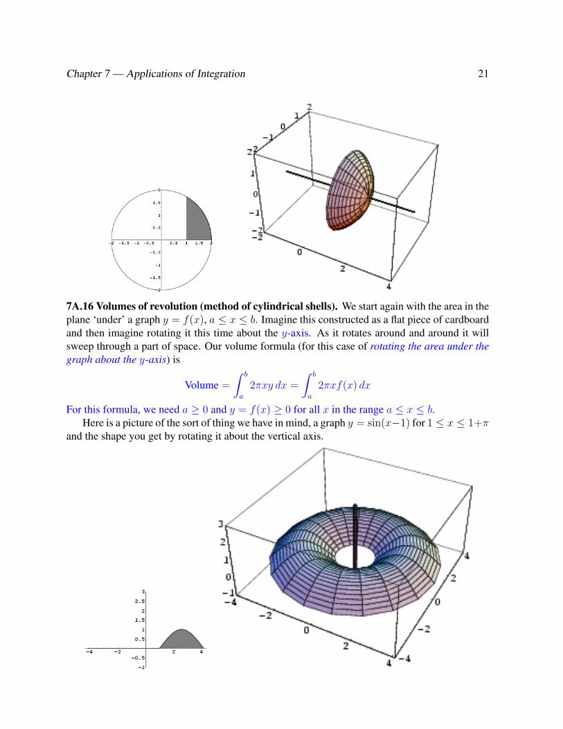
7A.16 Volumes of revolution (method of cylindrical shells). We start again with the area in theplane ‘under’ a graph y = f(x), a ≤ x ≤ b. Imagine this constructed as a flat piece of cardboardand then imagine rotating it this time about the y-axis. As it rotates around and around it willsweep through a part of space. Our volume formula (for this case of rotating the area under thegraph about the y-axis) is
Volume =
∫ b
a
2πxy dx =
∫ b
a
2πxf(x) dx
For this formula, we need a ≥ 0 and y = f(x) ≥ 0 for all x in the range a ≤ x ≤ b.Here is a picture of the sort of thing we have in mind, a graph y = sin(x−1) for 1 ≤ x ≤ 1+π
and the shape you get by rotating it about the vertical axis.

22 1S3 2006–07 R. Timoney
We again justify this by starting with a thin (infinitesimally thin) strip of the region under thegraph, from x to x + dx and seeing what happens when we rotate that about the y-axis. Thispencil-like thing rotates though a thin shell. Or maybe you would like to think of it as a sectionof pipe. (The wall of the pipe is thin, but not quite zero, so that there is a volume of materialneeded to make the section of pipe. We are going to ‘add’ the volumes of these things.) Here isa picture of one.
The shell/pipe has inside radius x, outside radius x + dx and height y = f(x). We get itsvolume by filling it in to get a solid cylinder and subtracting the volume required to fill it.
Remember that the formula for the volume of a cylinder is πr2h. To fill the thing in we needto add a volume of πx2y = πx2f(x) and when we fill it in we will have a solid cylinder of radiusx + dx, height y = f(x) and so the volume after filling it in is π(x + dx)2y = π(x + dx)2f(x).So, subtracting, we get
volume of shell = π(x + dx)2y − πx2y
= π(x2 + 2xdx + (dx)2 − x2)y
= 2πxy dx + πy(dx)2
I don’t want the πy(dx)2 term and so I’m going to ignore it. That is not so bad a thing todo because it is really very small. dx is already infinitesimal (= unbelievably small) and (dx)2 isan unbelievably small fraction of something that is already unbelievably small. Perhaps a moreconvincing argument uses limits instead of infinitesimals. If we did things with Riemann sums,we would have small finite widths ∆x instead of infinitesimals dx. Then we would need somefairly large number n steps of size ∆x to get from x = a to x = b. In fact ∆x =
b− a
n. When

Chapter 7 — Applications of Integration 23
we add up the n different quantities for the volumes of the n slices, the sum of the n quantities
πy(∆x)2 = πy
(b− a
n
)2
will still have an n in the denominator and so their contribution will → 0 as n →∞.In any case, we can ignore the πy(dx)2 bit and add up the rest to get∫ b
x=a
2πxy dx
We would not be doing this right if x < 0 ever happened. We took x as a radius and so it neededto be positive. Also we really needed y = f(x) = a height to be positive.
7A.17 Example. For the same graph as in the previous example
y =√
4− x2 (1 ≤ x ≤ 2)
find the volume swept out when we rotate the region under this graph about the (vertical) y-axis.Solution: This is all set up to use the formula and we get
Volume =
∫ 2
x=1
2πxy dx =
∫ 2
x=1
2πx√
4− x2 dx
and after some work . . . this turns out to be 2π√
3.Here is a picture of the object. The picture is cut away to help see what it looks like. (If you
took a half ball of radius 2 and drilled a hole of radius 1 out of it, this is what would be left.)
Richard M. Timoney May 11, 2007