CHAPTER 7. APPENDICES - srxtt.swipeout.netsrxtt.swipeout.net/files/srx_07.pdf · SPECIFICATIONS...
26
- - CHAPTER 7. APPENDICES SPECIFICATIONS ............................................. 7-l GENERAL SPECIFICATIONS ................................. 7-l MAINTENANCE SPECIFICATIONS ............................ 7-4 GENERAL TORQUE SPECIFICATIONS.. . . . . . . . . . . . . . . . . . . . . . . . . . . 7-17 DEFlNlTlONOFUNlTS........................................7-17 LUBRICATION DIAGRAM.. . . . . . . . . . . . . . . . . . . . . . . . . . . . . . . . . . . . . 7-18 - CABLE ROUTING.. . . . . . . . . . . . . . . . . . . . . . . . . . . . . . . . . . . . . . . . . . . . 7-22 - SRXGOOS COLOR WIRING DIAGRAM - -
Transcript of CHAPTER 7. APPENDICES - srxtt.swipeout.netsrxtt.swipeout.net/files/srx_07.pdf · SPECIFICATIONS...

-
-
CHAPTER 7.APPENDICES
SPECIFICATIONS . . . . . . . . . . . . . . . . . . . . . . . . . . . . . . . . . . . . . . . . . . . . . 7-lGENERAL SPECIFICATIONS . . . . . . . . . . . . . . . . . . . . . . . . . . . . . . . . . 7-lMAINTENANCE SPECIFICATIONS . . . . . . . . . . . . . . . . . . . . . . . . . . . . 7-4
GENERAL TORQUE SPECIFICATIONS.. . . . . . . . . . . . . . . . . . . . . . . . . . . 7-17
DEFlNlTlONOFUNlTS........................................7-17
LUBRICATION DIAGRAM.. . . . . . . . . . . . . . . . . . . . . . . . . . . . . . . . . . . . . 7-18-
CABLE ROUTING.. . . . . . . . . . . . . . . . . . . . . . . . . . . . . . . . . . . . . . . . . . . . 7-22
- SRXGOOS COLOR WIRING DIAGRAM
-
-

l=TKl SPECIFICATIONS
APPENDICESSPECIFICATIONSGENERAL SPECIFICATIONS
Model
Model Code Number:
Vehicle Identification Number:
Engine Starting Number:
3imensions:Overal I LengthOverall WidthOverall HeightSeat HeightWheelbaseMinimum Ground Clearance
Basic Weight:With Oil and Full Fuel Tank
Minimum Turning Radius
Engine:Engine TypeCylinder ArrangementDisplacementBore x StrokeCompression RatioCompression PressureStarting System
Lubrication System
Oil Type or Grade:Engine Oil
SRX600S
2EH
JYA2EHOO * GAO00101
2EH-000101
2,120 mm (83.5 in)705 mm (27.8 in)
1,055 mm (41.5 in)760 mm (29.9 in)
1,385 mm (54.5 in)145 mm ( 5.7 in)
176 kg (388 lb)
2,600 mm (102.4 in)
Air cooled 4-stroke, SOHCSingle cylinder595 cm395.0 x 84.0 mm (3.740 x 3.307 in)8.5 : 11,177 kPa (12 kg/cm’, 171 psi)Kick starter
Dry sump
Yamalube 4-cycle oil orSAE 2OW40 type SE motor oil
Oil Capacity:Engine Oil:
Periodic Oil ChangeWith Oil Filter ReplacementTotal Amount
Air FilterFuel:TypeTank CapacityReserve Amount
Carburetor:Type/Manufacturer
Spark Plug:Type/ManufacturerGap
2.0 L (1.8 Imp qt, 2.1 US qt)2.1 L (1.9 Imp qt, 2.2 US qt)2.4 L (2.1 Imp qt, 2.5 US qt)
Dry type element
Regular gasoline15.0 L (3.3 Imp gal, 4.0 US gal)3.0 L (0.7 Imp gal, 0.8 US gal)
Y27PV x l/TEIKEI KIKAI
DPR7EA-9, DPR8EA-9, DR7ES/NGKFor DP type: 0.8 - 0.9 mm (0.031 - 0.035 in)For D type: 0.6 - 0.7 mm (0.024 - 0.028 in)
Clutch Type Wet, multiple-disc
-
7-1

-SPECIFICdTlflNS b=kd --- --.- .-* . . .-.w- - .
ModelTransmission:
Primary Reduction SystemPrimary Reduction RatioSecondary Reduction SystemSecondary Reduction RatioTransmission TypeOperationGear Ratio: 1st
2 n d3rd4th5th
Chassis:Frame TypeCaster AngleTrail
Tire:TypeSize (Front)
Size (Rear)
Wear Limit
Tire Pressure (Cold Tire):Basic Weight:With Oil and Full Fuel Tank
Maximum Load*
Cold Tire Pressure:
Up to 90 kg (198 lb) Load*
90 kg (198 lb)*- Maximum Load*
High Speed Riding
Brake:Front Brake TypeOperationRear Brake TypeOperation
Suspension:Front SuspensionRear Suspension
Shock Absorber:Front Shock AbsorberRear Shock Absorber
Wheel Travel:Front Wheel TravelRear Wheel Travel
S R X6OOS
Gear74/31 (2.387)Chain37/15 (2.466)Constant mesh, 5-speedLeft foot operation30/13 (2.307)27/l 7 (1.588)24/20 ( 1.200)21/22 (0.954)21/27 (0.777)
Double cradle26”103 mm (4.06 in)
Tubeless100/80-18 53sBRIDGESTONE YKD120/80- 18 62sBRIDGESTONE KJK1.0 mm (0.04 in)
176 kg (388 I b)204 kg (450 lb)
FRONT REAR
177 kPa 196 kPa( 1.8 kg/cm’ , 26 psi) (2.0 kg/cm’, 28 psi)
196 kPa 226 kPa(2.0 kg/cm’, 28 psi) (2.3 kg/cm2, 32 psi)
196 kPa 226 kPa(2.0 kglcm2, 28 psi) (2.3 kg/cm’, 32 psi)
* Load is the total weight of cargo, rider,passenger, and accessories.
Dual disc brakeRight hand operationSingle disc brakeRight foot operation
Telescopic forkSwingarm
Coil spring, Oil damperCoil spring, Oil/Gas damper
140 mm (5.5 in)100 mm (3.9 in)
7-2
I=liq SPECIFICATIONS
Model
Electrical:Ignition SystemGenerator SystemBattery TypeBattery Capacity
Headlight Type
Bubl Wattage/Quantity:HeadlightTail/Brake LightFlasher LightIndicator Light:“NEUTRAL”“HIGH BEAM”“TURN”
Meter Light
SR X6OOS
CDIAC Magneto generator12N5-3B12V, 5AH
Bulb type (Quartz bulb)
12V, 6OW/55W x 112V, 8W/27W x 112V, 27W x 4
12v, 3.4w x 112v, 3.4w x 112v, 3.4w x 112v, 3.4w x 2
7-3
-
-
-
-
-
-
-
-
-
-
-
-
-
-
-
-
-
-
SPECIFICATIONS pqpq -
MAINTENANCE SPECIFICATIONS
ngine
Model S R X6OOS
Cylinder Head:Warp Limit
Cylinder:Bore SizeMeasuring Point*Out of Round Limit
Camshaft:Drive MethodCam Cap Inside DiameterCamshaft Outside DiameterShaft-to-cap ClearanceCam Dimensions:
Intake:“A” 4< Limit >“B”< Limit >“C”
Exhaust:“Ali< Limit >“B”
C
n
0 A< Limit > I - - B - J“C”
Camshaft Runout Limit
Cam Chain Type/Number of LinksCam Chain Adjustment Method
Rocker Arm/Rocker Arm Shaft:.Arm Inside Diameter< Limit >Shaft Outside Diameter< Limit >Arm-to-shaft Clearance
< 0.03 mm (0.0012 in) >CLines indicate straightedge measurement.
95.00 - 95.02 mm (3.740 - 3.741 in)40 mm (1.57 in)0.05 mm (0.002 in)
Chain (Left)23.000 - 23.021 mm (0.9055 - 0.9063 in)22.967 - 22.980 mm (0.9042 - 0.9047 in)0.020 - 0.054 mm (0.0008 - 0.0021 in)
36.47 - 36.57 m m (1.436 - 1.440 in)< 36.42 mm (1.434 in) >30.06 - 30.16 m m (1.183 - 1.187 in)< 30.01 mm (1.182 in) >6.41 mm (0.252 in)
36.62 - 36.72 m m (1.442 - 1.446 in)< 36.57 mm (1.440 in) >30.11 - 30.21 m m (1.185 - 1.189 in)< 30.06 mm (1.184 in) >6.51 mm (0.256 in)< 0.03 mm (0.001 in) >
75-010/126 LinksAutomatic
12.000 - 12.018 mm (0.4724 - 0.4731 in)< 12.05 mm (0.474 in) >11.976 - 11.991 mm (0.4715 - 0.4721 in)< 11.95 mm (0.471 in) >0.009 - 0.042 mm (0.0004 - 0.0017 in)
q
7-4

SPECIFICATIONS-
Model
dalve, Valve Seat, Valve Guide:Valve Clearance (Cold):
SRXGOOS
Valve Dimensions:
0.05 - 0.10 mm (0.002 - 0.004 in)0.12 - 0.17 mm (0.005 - 0.007 in)
Head Dia. Face Width Seat Width Margin Thickness
“A” Head Diameter:
“B” Face Width:
“C” Seat Width:
< Limit >
“D” Margin Thickness:
< Limit >
Stem Outside Diameter:
< Limit >
Guide Inside Diameter:
< Limit >
Stem-to-guide Clearance:
< Limit >
Stem Runout Limit
IN. 35.9 - 36.1 mm (1.413 - 1.421 in)EX. 30.9 - 31.1 mm (1.217 - 1.224 in)IN. 2.26 mm (0.089 in)EX. 2.26 mm (0.089 in)IN. 1 .O - 1.2 mm (0.039 - 0.047 in)EX. 1 .O - 1.2 mm (0.039 - 0.047 in)IN. < 2.0 mm (0.080 in) >EX. < 2.0 mm (0.080 in) >IN. 1.0 - 1.4 mm (0.039 - 0.055 in)EX. 0.8 - 1.2 mm (0.031 - 0.047 in)IN. < 0.7 mm (0.028 in) >EX. < 0.7 mm (0.028 in) >IN. 6.975 - 6.990 mm (0.2746 - 0.2752 in)EX. 6.955 - 6.970 mm (0.2738 - 0.2744 in)IN. < 6.945 mm (0.273 in) >EX. < 6.915 mm (0.272 in) >IN. 7.000 - 7.012 mm (0.2756 - 0.2761 in)EX. 7.000 - 7.012 mm (0.2756 - 0.2761 in)IN. < 7.10 mm (0.280 in) >EX. < 7.10 mm (0.280 in) >IN. 0.010 - 0.037 mm (0.0004 - 0.0015 in)EX. 0.030 - 0.057 mm (0.0012 - 0.0022 in)IN. < 0.10 mm (0.004 in) >EX. < 0.12 mm (0.005 in) >
< 0.01 mm (0.0004 in) >

-r
SPECIFICATIONS APpx k \
Model
Valve Spring:Inner Spring:
Free Length IN.EX.
< Limit > IN.EX.
Set Length (Valve Closed) IN.EX.
Compressed Pressure (Installed) IN.EX.
Tilt Limit * IN.
-$i
SRX6OOS
40.1 mm (1.58 in)40.1 mm (1.58 in)< 38.1 mm (1.50 in) >< 38.1 mm (1.50 in) >22.7 mm (0.89 in)22.7 mm (0.89 in)16.8 - 19.4 kg (37.0 - 42.8 lb)16.8 - 19.4 kg (37.0 - 42.8 lb)< 2.5”/1.7 mm (0.067 in) >< 2.5”/1.7 mm (0.067 in) >
Aa/:
Direction of Winding IN.EX.
Outer Spring:Free Length IN.
EX.< Limit > IN.
EX.Set Length (Valve Closed) IN.
EX.Compressed Pressure ( I nstal led) I N,
EX.Tilt Limit Jc IN.
$2
RightRight
43.8 mm (1.72 in)43.8 mm (1.72 in)< 41.8 mm (1.65 in) >< 41.8 mm (1.65 in) >34.2 mm (1.35 in)34.2 mm (1.35 in)37.1 - 49.6 kg (81.8 - 109.3 lb)37.1 - 49.6 kg (81.8 - 109.3 lb)< 2.5”/1.7 mm (0.067 in) >< 2.5”/1.7 mm (0.067 in) >
di%i!E/4Direction of Winding IN. Left
EX. Left
Piston :Piston Size “D”/ 94.915 - 94.965 mm (3.737 - 3.739 in)/
Measuring Point “H” 5 mm (0.20 in)(From bottom line of piston skirt)
Piston Clearance 0.045 - 0.065 mm (0.0018 - 0.0026 in)Oversize: 2 n d H 95.50 mm (3.760 in)
4th 96.00 mm (3.780 in)q
7-6
(nPPxlll\l SPECIFICATIONSc I .
Model S R X6OOS
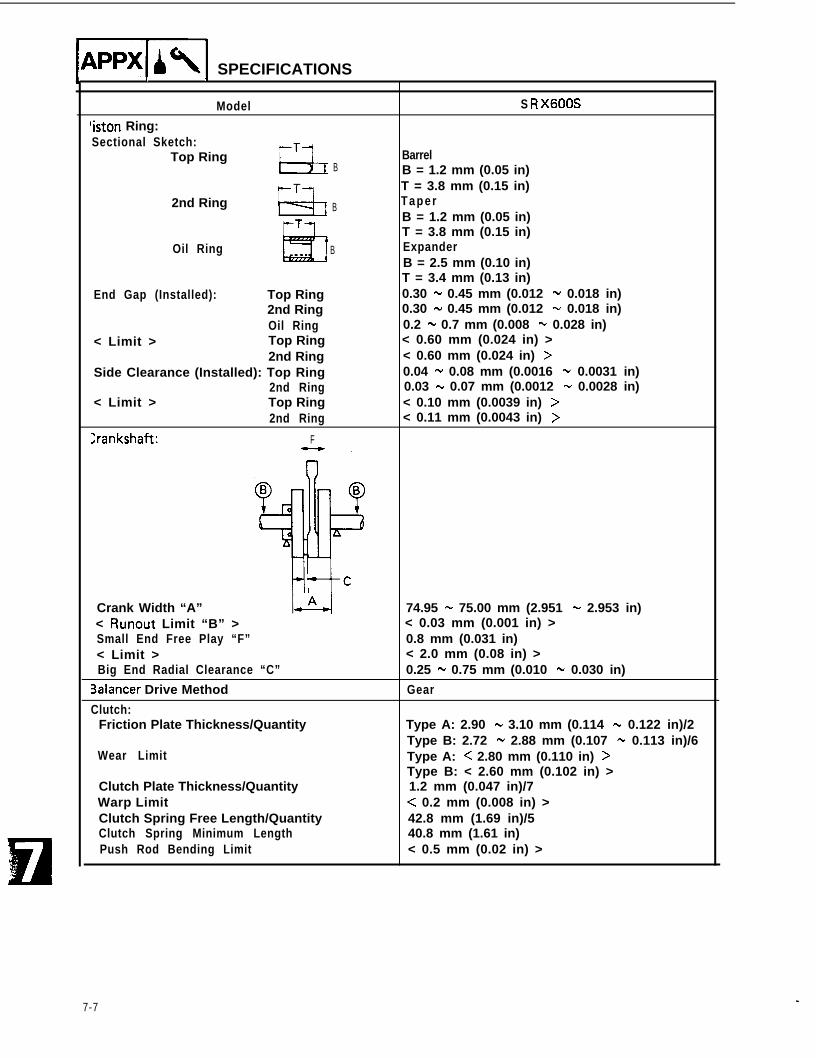
‘iston Ring:Sectional Sketch:
Top Ringl--T
t4IBarrel
B B = 1.2 mm (0.05 in)T
2nd RingLb
T = 3.8 mm (0.15 in)
B TaperB = 1.2 mm (0.05 in)T = 3.8 mm (0.15 in)
Oil Ring B ExpanderB = 2.5 mm (0.10 in)T = 3.4 mm (0.13 in)
End Gap (Installed): Top Ring 0.30 - 0.45 mm (0.012 - 0.018 in)2nd Ring 0.30 - 0.45 mm (0.012 - 0.018 in)Oil Ring 0.2 - 0.7 mm (0.008 - 0.028 in)
< Limit > Top Ring < 0.60 mm (0.024 in) >2nd Ring < 0.60 mm (0.024 in) >
Side Clearance (Installed): Top Ring 0.04 - 0.08 mm (0.0016 - 0.0031 in)2nd Ring 0.03 - 0.07 mm (0.0012 - 0.0028 in)
< Limit > Top Ring < 0.10 mm (0.0039 in) >2nd Ring < 0.11 mm (0.0043 in) >
Crankshaft: F
Crank Width “A”< Runout Limit “B” >Small End Free Play “F”< Limit >Big End Radial Clearance “C”
Balancer Drive Method
Clutch:Friction Plate Thickness/Quantity
Wear Limit
Clutch Plate Thickness/QuantityWarp LimitClutch Spring Free Length/QuantityClutch Spring Minimum LengthPush Rod Bending Limit
74.95 - 75.00 mm (2.951 - 2.953 in)< 0.03 mm (0.001 in) >0.8 mm (0.031 in)< 2.0 mm (0.08 in) >0.25 - 0.75 mm (0.010 - 0.030 in)
Gear
Type A: 2.90 - 3.10 mm (0.114 - 0.122 in)/2Type B: 2.72 - 2.88 mm (0.107 - 0.113 in)/6Type A: < 2.80 mm (0.110 in) >Type B: < 2.60 mm (0.102 in) >1.2 mm (0.047 in)/7< 0.2 mm (0.008 in) >42.8 mm (1.69 in)/540.8 mm (1.61 in)< 0.5 mm (0.02 in) >
7-7
SPECIFICATIONS IaKl
-
-
Model
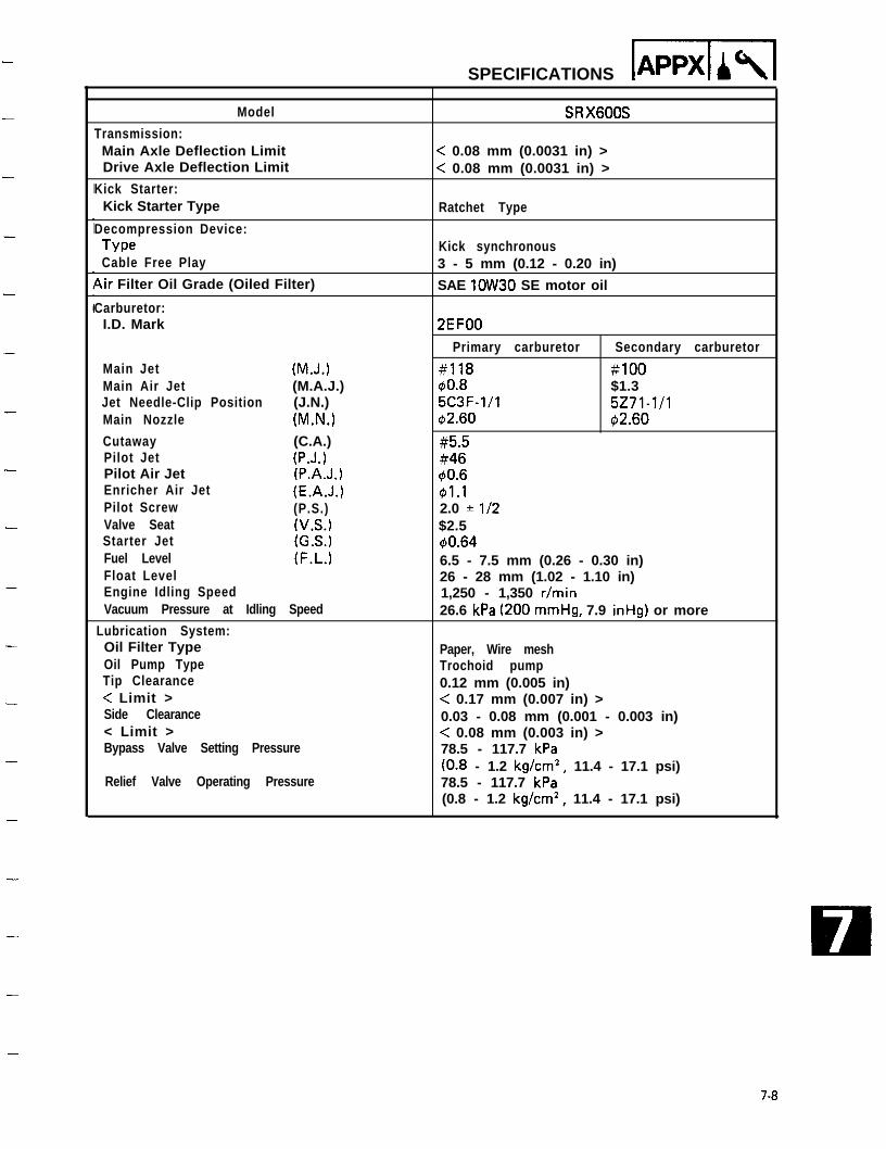
Transmission:Main Axle Deflection LimitDrive Axle Deflection Limit
Kick Starter:Kick Starter Type
Decompression Device:TypeCable Free Play
4ir Filter Oil Grade (Oiled Filter)
Carburetor:I.D. Mark
Main Jet (M.J.)Main Air Jet (M.A.J.)Jet Needle-Clip Position (J.N.)Main Nozzle (M.N.)
Cutaway (C.A.)Pilot Jet (P.J.)Pilot Air Jet (P.A.J.)Enricher Air Jet (E.A.J.)Pilot Screw (P.S.)Valve Seat (V.S.)Starter Jet (G.S.)Fuel Level (F.L.)Float LevelEngine Idling SpeedVacuum Pressure at Idling Speed
Lubrication System:Oil Filter TypeOil Pump TypeTip Clearance< Limit >Side Clearance< Limit >Bypass Valve Setting Pressure
Relief Valve Operating Pressure
SRX6OOS
< 0.08 mm (0.0031 in) >< 0.08 mm (0.0031 in) >
Ratchet Type
Kick synchronous3 - 5 mm (0.12 - 0.20 in)
SAE lOW30 SE motor oil
2EFOO
Primary carburetor Secondary carburetor
#118 #lOO$10.8 $1.35C3F-l/l 5271-l/142.60 $12.60
#5.5#46$0.6G1.12.0 * l/2$2.540.646.5 - 7.5 mm (0.26 - 0.30 in)26 - 28 mm (1.02 - 1.10 in)1,250 - 1,350 r/min26.6 kPa (200 mmHg, 7.9 inHg) or more
Paper, Wire meshTrochoid pump0.12 mm (0.005 in)< 0.17 mm (0.007 in) >0.03 - 0.08 mm (0.001 - 0.003 in)< 0.08 mm (0.003 in) >78.5 - 117.7 kPa(0.8 - 1.2 kg/cm2, 11.4 - 17.1 psi)78.5 - 117.7 kPa(0.8 - 1.2 kg/cm2, 11.4 - 17.1 psi)
7-8
lAPPXl SPECIFICATIONS
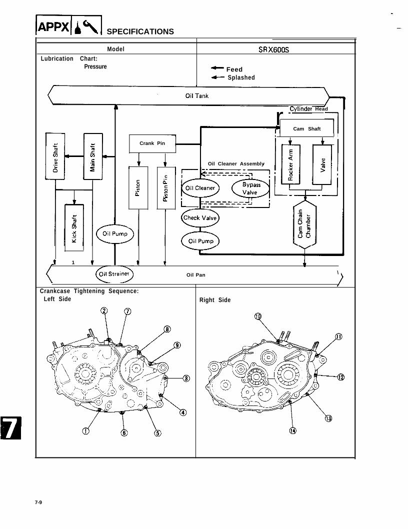
ModelLubrication Chart:
Pressure
SRX600S
^ Feed- Splashed
Crank Pin
r -Cylinder Head
Cam Shaft 1I
f 1 1 Oil Cleaner Assembly
c
s 6-t;b-
Ez.-
eL
I 1 1 t
\
Crankcase Tightening Sequence:Left Side
T
Oil Pan \
Right Side
7-9

-
-
r
-
-
-
-
-
-
-
-
--
-
-
.-
-
-
-
-
Tightening Torque
SPECIFICATIONS lpspxll-
Parts to be tightened Part nameTightening torque
T h r e a d s i z e Q’ty Nm1 m-kg 1 ftaib
Remarks
ENGINE:
Cyinder Head Flange bolt M8 x 1.25 4 25 2.5 18Nut MlOx 1.25 2 20 2.0 14Bolt M6 1 10 1.0 7.2
Stud bolt M6 4 7 0.7 5.1Spark Plug - M12x 1.25 1 17.5 1.75 12.5Cylinder Head Cover Bolt M6 16 10 1.0 7.2Tappet Cover Bolt M6 2 10 1.0 7.2
Bolt M32 x 1.5 2 12 1.2 8.7Cylinder Cap nut M8 x 1.25 2 22 2.2 16
Nut MlOx 1.25 4 38 3.8 27Bolt M 6 x 1 . 2 5 2 10 1.0 7.2
Balance Weight Gear Nut Ml6 x 1.0 1 90 9.0 65 f;;,sc”
A.C. Generator Rotor N u t Ml4 x 1.5 1 90 9.0 65Valve Clearance Nut M6 4 14 1.4 10Stopper Guide Bolt M6 2 8 0.8 5.8Cam Sprocket Flange bolt M 7 2 20 2.0 14Tensioner Assembly Bolt M6 2 10 1.0 7.2Decompression Cam Bolt M6 1 8 0.8 5.8Rocker Shaft Stopper Bolt M6 2 10 1.0 7.2Oil Pump Assembly Bolt M6 3 10 1.0 7.2Oil Pump Cover Screw M6 1 7 0.7 5.1Strainer Housing Screw M6 2 7 0.7 5.1Drain Plug Plug Ml4 x 1.5 1 30 3.0 22Oil Filter Cover Bolt M6 3 10 1.0 7.2Oil Filter Air Bleed Screw M5 1 5 0.5 3.6Oil Hose Bolt M6 4 10 1.0 7.2
Union nut Ml6 x 1.5 2 50 5.0 36Carburetor Joint Bolt M6 4 10 1.0 7.2Carburetor Assembly Hose clamp M4 2 2 0.2 1.4Exhaust Pipe Nut M6 4 10 1.0 7.2Exhaust Pipe Protector Screw M6 2 7 0.7Outlet Pipe
5 . 1 QScrew M6 1 7 0.7 5.1
Exhaust Pipe Muffler Joint Bolt M8 x 1.25 1 20 2.0 14Muffler Mounting Bolt MB x 1.25 2 27 2.7 19Crankcase Bolt M6 14 10 1.0 7.2Crankcase Stud bolt MlOx 1.25 4 20 2.0 14Clamp (Lead) Screw M6 1 7 0.7 5.1Decompression Cover Bolt M6 2 10 1.0 7.2Bridge Plate Cover Screw M6 3 7 0.7 5.1Ratchet Wheel Guide Bolt M6 2 10 1.0 7.2Decompression Lever Nut M6 1 8 0.8 5.8
7-10
Ipspxllcl\ SPECIFICATIONS
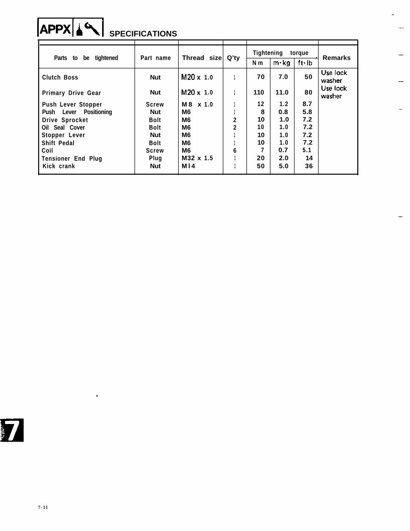
Parts to be tightened
Clutch Boss
Primary Drive Gear
Push Lever StopperPush Lever PositioningDrive SprocketOil Seal CoverStopper LeverShift PedalCoilTensioner End PlugKick crank
Part name Thread size Q’tyTightening torque
- RemarksN m makg ftalb
Nut M20x 1.0 1 70 7.0 50 fz;;;”
Nut M20x 1.0 1 110 11.0 80 i;;;;”
Screw M 8 x 1.0 1 12 1.2 8.7Nut M6 1 8 0.8 5.8Bolt M6 2 10 1.0 7.2Bolt M6 2 10 1.0 7.2Nut M6 1 10 1.0 7.2Bolt M6 1 10 1.0 7.2
Screw M6 6 7 0.7 5.1Plug M32 x 1.5 1 20 2.0 14Nut M l 4 1 50 5.0 36
-
.
7-11
-SPECIFICATIONS
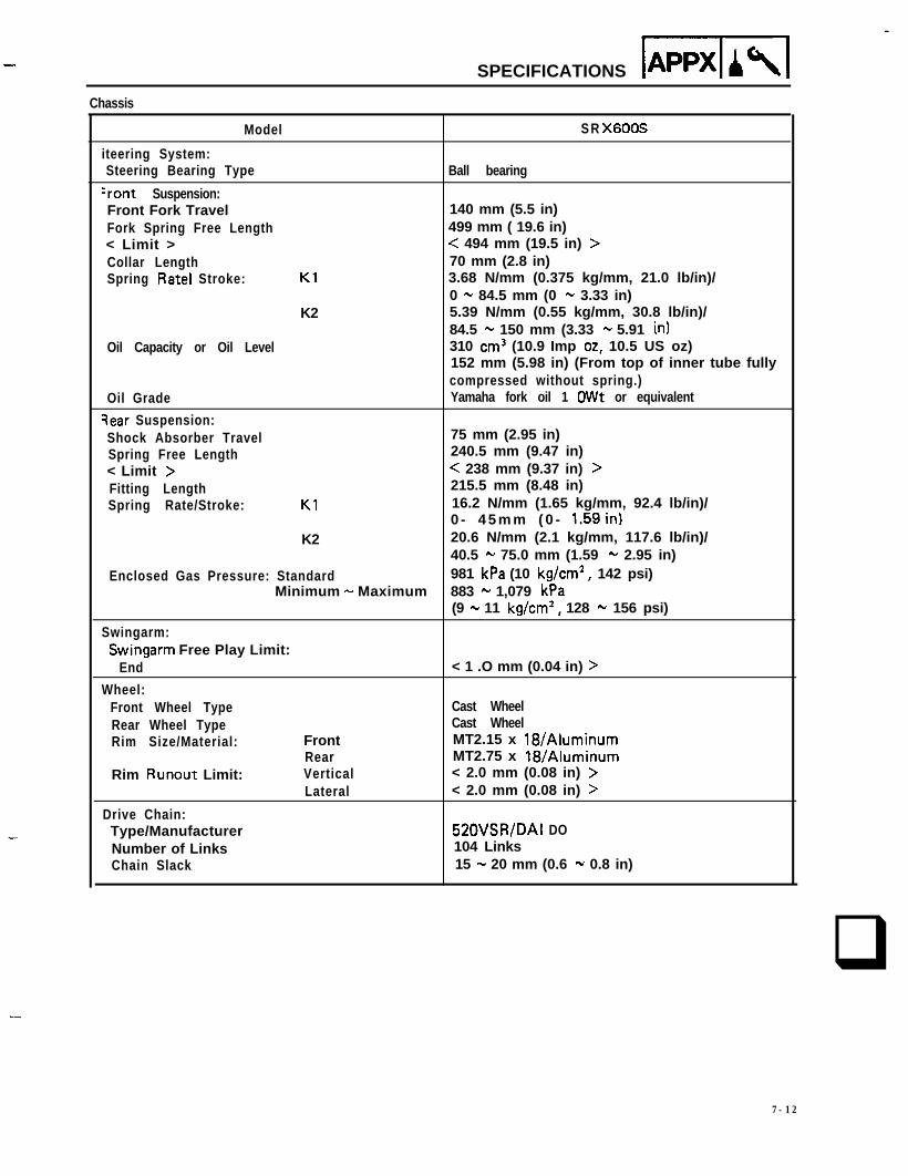
Chassis
Model S R X6OOS
iteering System:Steering Bearing Type Ball bearing
‘rant Suspension:Front Fork Travel 140 mm (5.5 in)Fork Spring Free Length 499 mm ( 19.6 in)< Limit > < 494 mm (19.5 in) >Collar Length 70 mm (2.8 in)Spring Rate1 Stroke: Kl 3.68 N/mm (0.375 kg/mm, 21.0 lb/in)/
0 - 84.5 mm (0 - 3.33 in)K2 5.39 N/mm (0.55 kg/mm, 30.8 lb/in)/
84.5 - 150 mm (3.33 - 5.91 in)Oil Capacity or Oil Level 310 cm3 (10.9 Imp 02, 10.5 US oz)
152 mm (5.98 in) (From top of inner tube fullycompressed without spring.)
Oil Grade Yamaha fork oil 1 OWt or equivalent
qear Suspension:Shock Absorber Travel 75 mm (2.95 in)Spring Free Length 240.5 mm (9.47 in)< Limit > < 238 mm (9.37 in) >Fitting Length 215.5 mm (8.48 in)Spring Rate/Stroke: Kl 16.2 N/mm (1.65 kg/mm, 92.4 lb/in)/
0 - 4 5 m m ( 0 - 1.59in)K2 20.6 N/mm (2.1 kg/mm, 117.6 lb/in)/
40.5 - 75.0 mm (1.59 - 2.95 in)Enclosed Gas Pressure: Standard 981 kPa (10 kg/cm2, 142 psi)
Minimum - Maximum 883 - 1,079 kPa(9 - 11 kg/cm2, 128 - 156 psi)
Swingarm:Swingarm Free Play Limit:
End < 1 .O mm (0.04 in) >
Wheel:Front Wheel Type Cast WheelRear Wheel Type Cast WheelRim Size/Material: Front MT2.15 x 18/Aluminum
Rear MT2.75 x 18/AluminumRim Runout Limit: Vertical < 2.0 mm (0.08 in) >
Lateral < 2.0 mm (0.08 in) >
Drive Chain:Type/Manufacturer 520VSR/DAI DONumber of Links 104 LinksChain Slack 15 - 20 mm (0.6 - 0.8 in)
q
7-12
IAPPxlr91 SPECIFICATIONSI I I
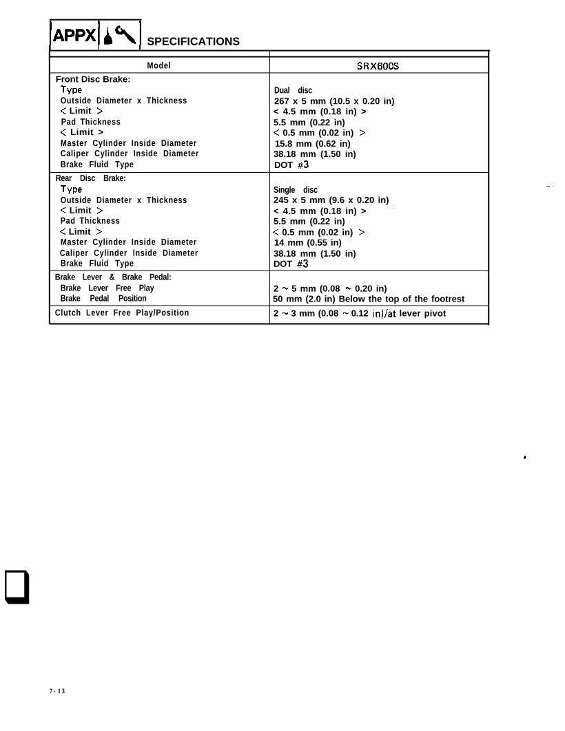
Model SRX6OOSFront Disc Brake:Type Dual discOutside Diameter x Thickness 267 x 5 mm (10.5 x 0.20 in)< Limit > < 4.5 mm (0.18 in) >Pad Thickness 5.5 mm (0.22 in)< Limit > < 0.5 mm (0.02 in) >Master Cylinder Inside Diameter 15.8 mm (0.62 in)Caliper Cylinder Inside Diameter 38.18 mm (1.50 in)Brake Fluid Type DOT #3
Rear Disc Brake:Type Single discOutside Diameter x Thickness 245 x 5 mm (9.6 x 0.20 in)< Limit > < 4.5 mm (0.18 in) > ’Pad Thickness 5.5 mm (0.22 in)< Limit > < 0.5 mm (0.02 in) >Master Cylinder Inside Diameter 14 mm (0.55 in)Caliper Cylinder Inside Diameter 38.18 mm (1.50 in)Brake Fluid Type DOT #3
Brake Lever & Brake Pedal:Brake Lever Free Play 2 - 5 mm (0.08 - 0.20 in)Brake Pedal Position 50 mm (2.0 in) Below the top of the footrest
Clutch Lever Free Play/Position 2 - 3 mm (0.08 - 0.12 in)/at lever pivot
.
q
7-13

Tiahtenino Toraue
Parts to be tightened Thread size .Tightening torque
N m m - k g ft.lbR e m a r k s
CHASSIS:
Front Wheel Axle M14x 1.5 105 10.5 75Rear Wheel Axle M16x 1.5 105 10.5 75Front Fork and Fork Brace M6 x 1.0 9 0.9 6.5Steering Crown and Inner Tube M8 x 1.25 20 2.0 14Steering Crown and Steering Shaft M22x 1.0 110 11.0 80Handlebar and Inner Tube M8 x 1.25 20 2.0 14Handlebar and Steering Crown M6 x 1.0 9 0.9 6.5Steering Shaft and Ring Nut M25x 1.0 38 3.8 27 S e e NOTEFront Master Cylinder and Master Bracket M6 x 1.0 9 0.9 6.5Front Master Cylinder and
Master Cylinder Cap M5 x 0.8 1 0.1 0.7
Brake Hose and Union Bolt MlOx 1.25 25 2.5 18Brake Joint and Under Bracket M6 x 1.0 9 0.9 6.5Caliper and Bleed Screw M8 x 1.25 5 0.5 3.6Front Caliper and Front Fork MlOx 1.25 35 3.5 25Engine Stay and Frame M8 x 1.25 33 3.3 24Engine Mounting (Front Upper) MlOx 1.25 42 4.2 30Engine Mounting (Front Lower) MlOx 1.25 42 4.2 30Engine Mounting (Rear Upper) MlOx 1.25 42 4.2 30Engine Mounting (Rear Under) MlOx 1.25 42 4.2 30Engine Stay and Frame (Top) M8 x 1.25 33 3.3 24Engine Mounting (Top) MlOx 1.25 42 4.2 30Frame and Down Tube M8 x 1.25 25 2.5 18Pivot Shaft M14x 1.5 90 9.0 65Rear Shock Absorber (Top) M8 x 1.25 26 2.6 19Rear Shock Absorber (Bottom) MlOx 1.25 41 4.1 30Rear Master Cylinder and Frame M8 x 1.25 20 2.0 14Footrest Bracket and Frame M8 x 1.25 26 2.6 19Brake Disc and Cast Wheel M8 x 1.25 20 2.0Rear Caliper and Caliper Bracket
14 +JMlOx 1.25 35 3.5 25
Rear Sprocket Wheel M8 x 1.25 32 3.2 23 4Tension Bar M8 x 1.25 25 2.5 18Kick Crank Stopper and Frame M8 x 1.25 25 2.5 18Swingarm End and Swingarm M6 x 1.0 6 0.6 4.3Inner Tube and Under Bracket M12x 1.25 38 3.8 27Cross Tube and Down Tube MlOx 1.25 35 3.5 25Rear Footrest Bracket and Frame MlOx 1.25 64 6.4 46Rear Footrest Bracket and Frame MlOx 1.25 30 3.0 22
NOTE:1. First, tighten the ring nut approximately 38 Nm (3.8 m-kg, 27 ft. lb) by using the torque wrench,
then loosen the ring nut one turn.2. Retighten the ring nut 10 Nm (1.0 m-kg, 7.2 ft. lb).
-SPECIFICATIONS APPX A\ -
7-14

lAppwiI SPECIFICATIONS
Electrical
SRX6OOS
doltage
gnition System:Ignition Timing (B.T.D.C.)Advancer Type
4Q0
12v
12” at 1,200 r/minElectrical
?0d 30c:m
; 20.-
i=
s:= 10El
Engine Speed (x lo3 r/min)
Magneto-Model/ManufacturerPickup Coil Resistance (Color)
Source Coil Resistance (Color)
CDI Unit-Model/Manufacturer
Model/ManufacturerMinimum Spark GapPrimary Winding ResistanceSecondary Winding Resistance
VCD48/NIPPONDENSO92 - 138s2 at 20°C (68°F)(Green -White/Green)(Green - White/Red)84 - 156s2 at 20°C (68” F)(Brown - Red)QAB50/NIPPONDENSO
12970-102/NIPPONDENSO6 mm (0.24 in)0.48 - 0.72n at 20°C (68°F)5.2 - 7.8 kR at 20°C (68” F)
agneto generator
VCD48/NIPPON DENS014.5V, 11A at 5,000 r/min
0 1 2 3 4 5 6
Engine Speed (x lo3 r/min)
-
-
7-15
-
4
-
-
-
-
SPECIFICATIONS Appx b \r-r-l -
Model
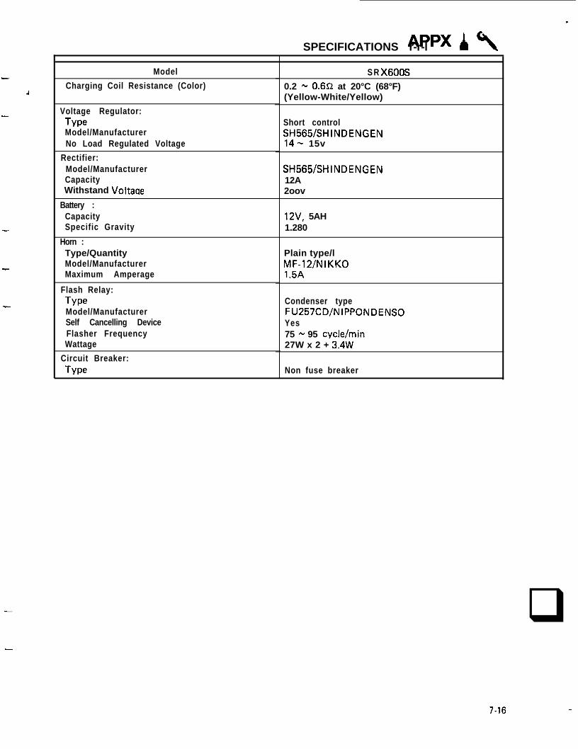
Charging Coil Resistance (Color)
Voltage Regulator:TypeModel/ManufacturerNo Load Regulated Voltage
Rectifier:Model/ManufacturerCapacityWithstand Voltage
Battery :CapacitySpecific Gravity
Horn :Type/QuantityModel/ManufacturerMaximum Amperage
Flash Relay:TypeModel/ManufacturerSelf Cancelling DeviceFlasher FrequencyWattage
Circuit Breaker:Type
S R X6OOS
0.2 - 0.6a at 20°C (68°F)(Yellow-White/Yellow)
Short controlSH565/SHINDENGEN14- 15v
SH565/SHINDENGEN12A2oov
12V, 5AH1.280
Plain type/lMF-12/NIKKO1.5A
Condenser typeFU257CD/NIPPONDENSOYes75 - 95 cyclelmin27W x 2 + 3.4W
Non fuse breaker
q-
7-16
APPX A\GENERAL TORQUE SPECIFICATIONS/DEFINITION OF UNITS
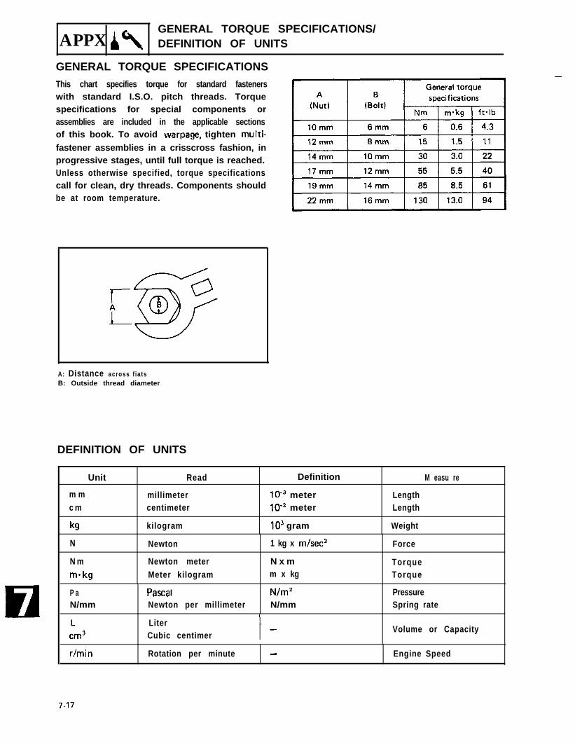
GENERAL TORQUE SPECIFICATIONSThis chart specifies torque for standard fastenerswith standard I.S.O. pitch threads. Torquespecifications for special components orassemblies are included in the applicable sectionsof this book. To avoid warpage, tighten multi-fastener assemblies in a crisscross fashion, inprogressive stages, until full torque is reached.Unless otherwise specified, torque specificationscall for clean, dry threads. Components shouldbe at room temperature.
-
A: Distance across f iatsB: Outside thread diameter
DEFINITION OF UNITS
Unit Read Definition M easu re
m m millimeter lo3 meter Lengthc m centimeter low2 meter Length
kg kilogram lo3 gram Weight
N Newton
N m Newton meterm-kg Meter kilogram
1 kg x m/sec2
N x mm x kg
Force
TorqueTorque
P aN/mm
Pasta INewton per millimeter
N/m2N/mm
PressureSpring rate
Lcm3
LiterCubic centimer
Volume or Capacity
r/min Rotation per minute - Engine Speed
7.17

-
LUBRICATION DIAGRAM
-
-
-
-
-
-
-
-
-
, I 1
LUBRICATION DIAGRAM lAPPXlA\I
1-j p+EqitB 1 SCAVENGE OIL
7-18
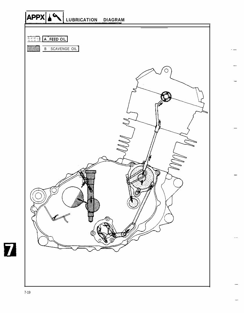
lA~P4I,\I LUBRICATION DIAGRAM
.I -1
~~~1 B 1 SCAVENGE OIL
-
7-19
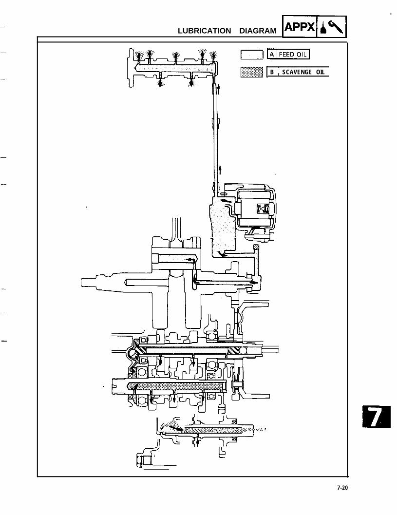
LUBRICATION DIAGRAM pqiy
-
~1 B 1 SCAVENGE OIL
\~~~+#$&:: : ,:::.:...:.:.:.:.. ..::.., . s ,.>. ;:.:.: :.:.:.: : : :c::‘,,:::, e .:.: :,.: :..
7-20

I..JmOIL(
~[ B 1 SCAVENGE OIL
LUBRICATION DIAGRAM
7-21

CABLE ROUTING IAPP4Al
CABLE ROUTING
@ Meter light lead@ Clutch cable
@ Handlebar switch(Left) lead
@ Starter cable@ Main switch lead
@ Wire harness@Speedometer cable
@ Front flasher light leads
-
-
-
-
-
-
-
-
(Left and right)
@ Tachometer cable
@ Throttle cables@ Handlebar switch
(Right) lead@ Front brake switch lead
@ Brake hose
q Connect the lead into the headlight body.
[83 Pass the handlebar switch (Left) lead behindthe clutch cable, and connect the lead into the
headlight body.q Cross the wire harness in front of the steering
head pipe.q Pass the handlebar switch (Right) lead behind
the brake hose, and connect the lead into theheadlight body.
7-22
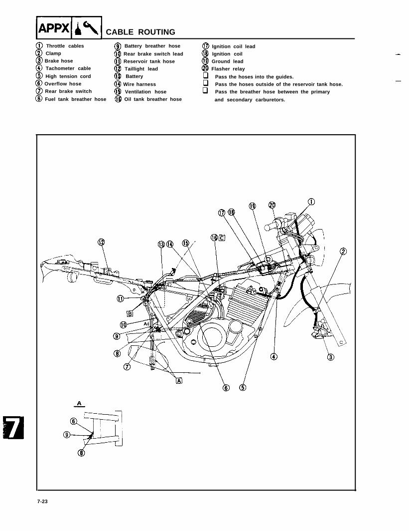
pqiq CABLE ROUTING
0 Throttle cables@I Clamp
@ Battery breather hose
@ Brake hose@ Rear brake switch lead
@ Tachometer cable@J Reservoir tank hose
@ High tension cord@ Taillight lead
@ Overflow hose@ Battery
0 Rear brake switch@ Wire harness
@ Fuel tank breather hose@ Ventilation hose@ Oil tank breather hose
@I Ignition coil lead@ Ignition coil@ Ground lead@ Flasher relay
q Pass the hoses into the guides.q Pass the hoses outside of the reservoir tank hose.q Pass the breather hose between the primary
and secondary carburetors.
-
7-23
-
-
-
-
-
-
-
-
-
--
-
-
-
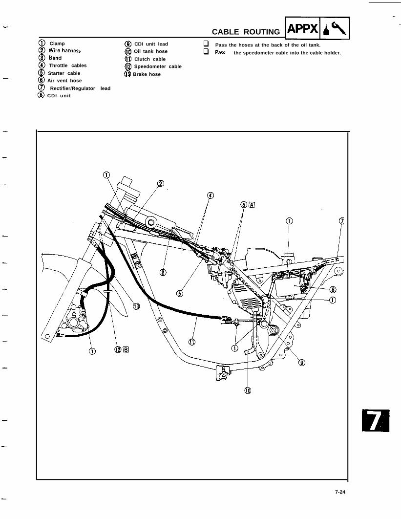
@ Clamp8 iiredharness
a n@ Throttle cables
@ Starter cable@ Air vent hose
0 Rectifier/Regulator lead@ CDI unit
@ CDI unit lead@ Oil tank hose
@ Clutch cable@I Speedometer cable
@ Brake hose
CABLE ROUTING
q Pass the hoses at the back of the oil tank.
q PaSS the speedometer cable into the cable holder.
-7-24
IA~Pud CABLE ROUTING
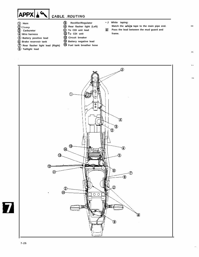
@) Horn @ Rectifier/Regulator •J White taping:
@ Clamp @ Rear flasher light (Left) Match the whi,te tape to the main pipe end.
@ Carburetor @ To CDI unit lead le] Pass the lead between the mud guard and
@ Wire harness @To CDI unit frame.
@ Battery positive lead @ Circuit breaker
@ Brake reservoir tank @ Battery negative lead
@ Rear flasher light lead (Right) @ Fuel tank breather hose
@ Taillight lead
-
-
-
-
7-25