
CHAPTER 6_PART III SHEET METALWORKING DPT 211 MANUFACTURING PROCESS 1.
40
CHAPTER 6_PART III SHEET METALWORKING DPT 211 MANUFACTURING PROCESS 1
-
Upload
austin-flowers -
Category
Documents
-
view
224 -
download
4
Transcript of CHAPTER 6_PART III SHEET METALWORKING DPT 211 MANUFACTURING PROCESS 1.
CHAPTER 6_PART III
SHEET METALWORKING
DPT 211MANUFACTURING PROCESS 1
©2007 John Wiley & Sons, Inc. M P Groover, Fundamentals of Modern Manufacturing 3/e
SHEET METALWORKING
1. Cutting Operations
2. Bending Operations
3. Drawing
4. Dies and Presses for Sheet Metal Processes

©2007 John Wiley & Sons, Inc. M P Groover, Fundamentals of Modern Manufacturing 3/e
Sheet Metalworking Defined
Cutting and forming operations performed on relatively thin sheets of metal
Thickness of sheet metal = 0.4 mm (1/64 in) to 6 mm (1/4 in)
Thickness of plate stock > 6 mm Operations usually performed as cold working

©2007 John Wiley & Sons, Inc. M P Groover, Fundamentals of Modern Manufacturing 3/e
Sheet and Plate Metal Products
Sheet and plate metal parts for consumer and industrial products such as Automobiles and trucks Airplanes Railway cars and locomotives Farm and construction equipment Small and large appliances Office furniture Computers and office equipment
©2007 John Wiley & Sons, Inc. M P Groover, Fundamentals of Modern Manufacturing 3/e
Advantages of Sheet Metal Parts
High strength Good dimensional accuracy Good surface finish Relatively low cost Economical mass production for large
quantities
©2007 John Wiley & Sons, Inc. M P Groover, Fundamentals of Modern Manufacturing 3/e
Sheet Metalworking Terminology
Punch‑and‑die - tooling to perform cutting, bending, and drawing
Stamping press - machine tool that performs most sheet metal operations
Stampings - sheet metal products
©2007 John Wiley & Sons, Inc. M P Groover, Fundamentals of Modern Manufacturing 3/e
Basic Types of Sheet Metal Processes
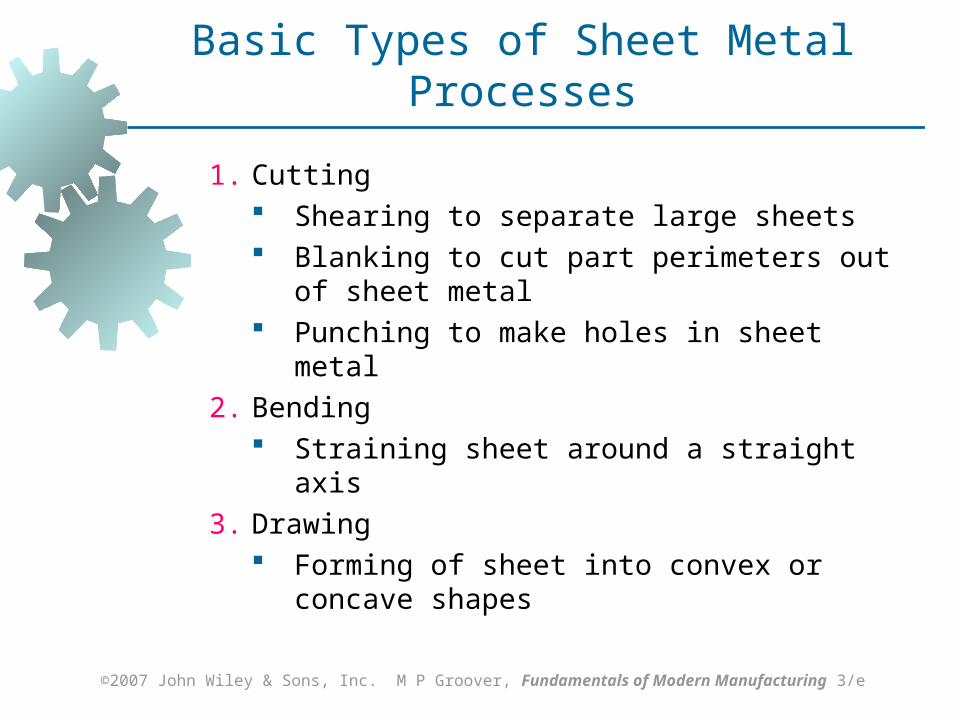
1. Cutting Shearing to separate large sheets Blanking to cut part perimeters out of
sheet metal Punching to make holes in sheet metal
2. Bending Straining sheet around a straight axis
3. Drawing Forming of sheet into convex or concave
shapes

©2007 John Wiley & Sons, Inc. M P Groover, Fundamentals of Modern Manufacturing 3/e
Figure 20.1 Shearing of sheet metal between two cutting edges: (1) just before the punch contacts work; (2) punch begins to push into work, causing plastic deformation;
Sheet Metal Cutting
©2007 John Wiley & Sons, Inc. M P Groover, Fundamentals of Modern Manufacturing 3/e
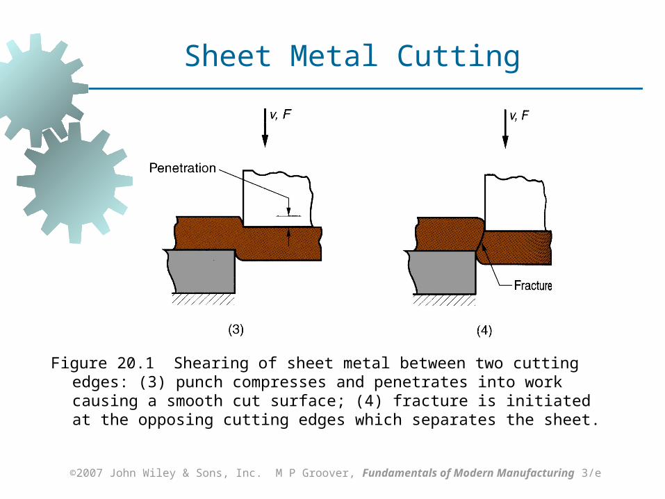
Figure 20.1 Shearing of sheet metal between two cutting edges: (3) punch compresses and penetrates into work causing a smooth cut surface; (4) fracture is initiated at the opposing cutting edges which separates the sheet.
Sheet Metal Cutting

©2007 John Wiley & Sons, Inc. M P Groover, Fundamentals of Modern Manufacturing 3/e
Shearing, Blanking, and Punching
Three principal operations in pressworking that cut sheet metal:
Shearing Blanking Punching

©2007 John Wiley & Sons, Inc. M P Groover, Fundamentals of Modern Manufacturing 3/e
Shearing
Sheet metal cutting operation along a straight line between two cutting edges
Typically used to cut large sheets
Figure 20.3 Shearing operation: (a) side view of the shearing operation; (b) front view of power shears equipped with inclined upper cutting blade.
©2007 John Wiley & Sons, Inc. M P Groover, Fundamentals of Modern Manufacturing 3/e
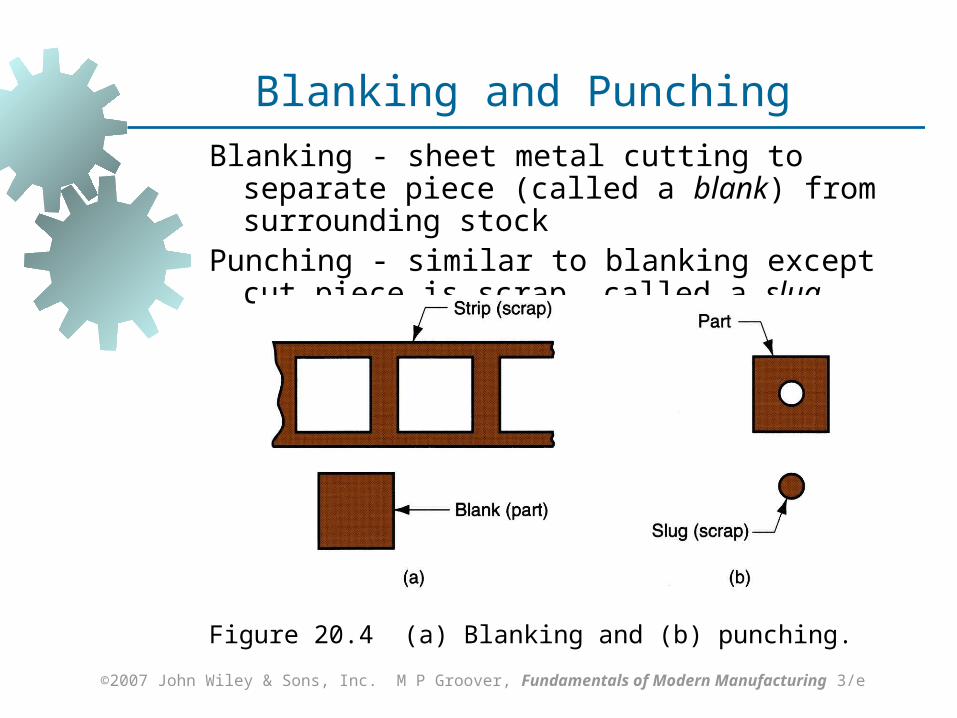
Blanking and Punching
Blanking - sheet metal cutting to separate piece (called a blank) from surrounding stock
Punching - similar to blanking except cut piece is scrap, called a slug
Figure 20.4 (a) Blanking and (b) punching.

©2007 John Wiley & Sons, Inc. M P Groover, Fundamentals of Modern Manufacturing 3/e
Clearance in Sheet Metal Cutting
Distance between punch cutting edge and die cutting edge
Typical values range between 4% and 8% of stock thickness If too small, fracture lines pass each other,
causing double burnishing and larger force If too large, metal is pinched between
cutting edges and excessive burr results

©2007 John Wiley & Sons, Inc. M P Groover, Fundamentals of Modern Manufacturing 3/e
Figure 20.6 Die size determines blank size Db; punch size determines hole size Dh.; c = clearance
Punch and Die Sizes
©2007 John Wiley & Sons, Inc. M P Groover, Fundamentals of Modern Manufacturing 3/e
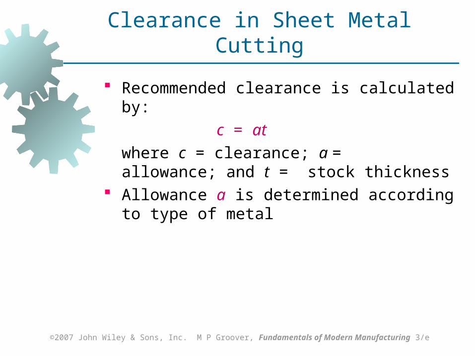
Clearance in Sheet Metal Cutting
Recommended clearance is calculated by:
c = at
where c = clearance; a = allowance; and t = stock thickness
Allowance a is determined according to type of metal

©2007 John Wiley & Sons, Inc. M P Groover, Fundamentals of Modern Manufacturing 3/e
Sheet Metal Groups Allowances
Metal group a
1100S and 5052S aluminum alloys, all tempers
0.045
2024ST and 6061ST aluminum alloys; brass, soft cold rolled steel, soft stainless steel
0.060
Cold rolled steel, half hard; stainless steel, half hard and full hard
0.075

©2007 John Wiley & Sons, Inc. M P Groover, Fundamentals of Modern Manufacturing 3/e
Figure 20.6 Die size determines blank size Db; punch size determines hole size Dh.; c = clearance
Punch and Die Sizes

©2007 John Wiley & Sons, Inc. M P Groover, Fundamentals of Modern Manufacturing 3/e
Punch and Die Sizes
For a round blank of diameter Db:
Blanking punch diameter = Db ‑ 2c
Blanking die diameter = Db
where c = clearance
For a round hole of diameter Dh:
Hole punch diameter = Dh
Hole die diameter = Dh + 2c
where c = clearance
©2007 John Wiley & Sons, Inc. M P Groover, Fundamentals of Modern Manufacturing 3/e
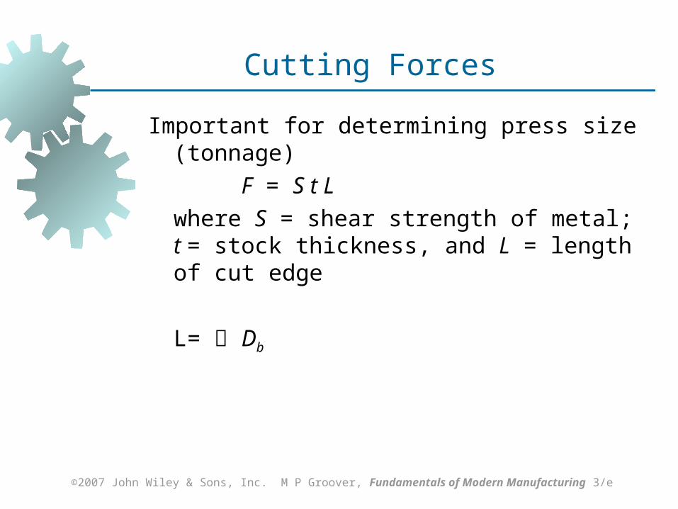
Cutting Forces
Important for determining press size (tonnage)
F = S t L
where S = shear strength of metal; t = stock thickness, and L = length of cut edge
L= Db

©2007 John Wiley & Sons, Inc. M P Groover, Fundamentals of Modern Manufacturing 3/e
Example Calculation of Blanking Clearance and Force
A round disk of 150 mm diameter is to be blanked from a strip of 3.2 mm, half-hard cold-rolled steel whose shear strength = 310 MPa. Determine (a) the appropriate punch diameters, and (b) blanking force.
©2007 John Wiley & Sons, Inc. M P Groover, Fundamentals of Modern Manufacturing 3/e
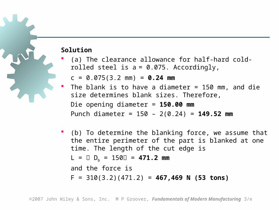
Solution (a) The clearance allowance for half-hard cold-rolled steel is
a = 0.075. Accordingly,
c = 0.075(3.2 mm) = 0.24 mm The blank is to have a diameter = 150 mm, and die size
determines blank sizes. Therefore, Die opening diameter = 150.00 mmPunch diameter = 150 – 2(0.24) = 149.52 mm
(b) To determine the blanking force, we assume that the entire perimeter of the part is blanked at one time. The length of the cut edge isL = Db = 150 = 471.2 mm
and the force isF = 310(3.2)(471.2) = 467,469 N (53 tons)
©2007 John Wiley & Sons, Inc. M P Groover, Fundamentals of Modern Manufacturing 3/e
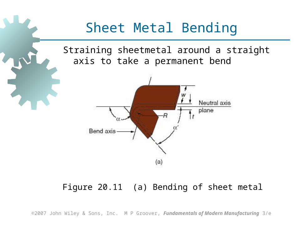
Straining sheetmetal around a straight axis to take a permanent bend
Figure 20.11 (a) Bending of sheet metal
Sheet Metal Bending

©2007 John Wiley & Sons, Inc. M P Groover, Fundamentals of Modern Manufacturing 3/e
Metal on inside of neutral plane is compressed, while metal on outside of neutral plane is stretched
Figure 20.11 (b) both compression and tensile elongation of the metal occur in bending.
Sheet Metal Bending

©2007 John Wiley & Sons, Inc. M P Groover, Fundamentals of Modern Manufacturing 3/e
Types of Sheet Metal Bending
V‑bending - performed with a V‑shaped die Edge bending - performed with a wiping die
©2007 John Wiley & Sons, Inc. M P Groover, Fundamentals of Modern Manufacturing 3/e
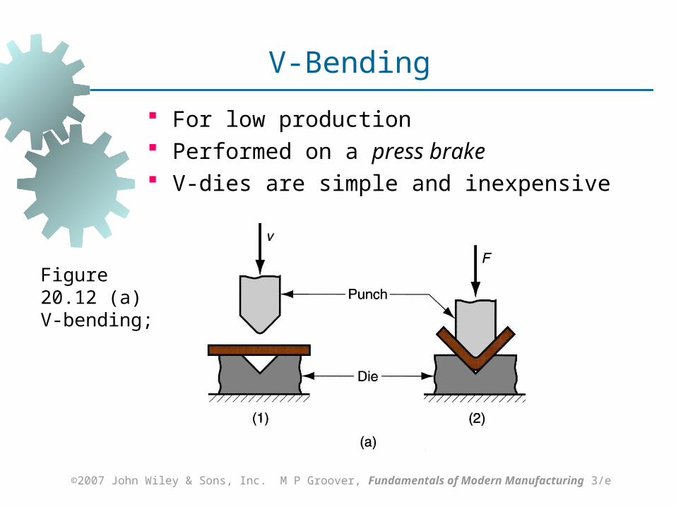
For low production Performed on a press brake V-dies are simple and inexpensive
Figure 20.12 (a) V‑bending;
V-Bending

©2007 John Wiley & Sons, Inc. M P Groover, Fundamentals of Modern Manufacturing 3/e
For high production Pressure pad required Dies are more complicated and costly
Edge Bending
Figure 20.12 (b) edge bending.
©2007 John Wiley & Sons, Inc. M P Groover, Fundamentals of Modern Manufacturing 3/e
Drawing
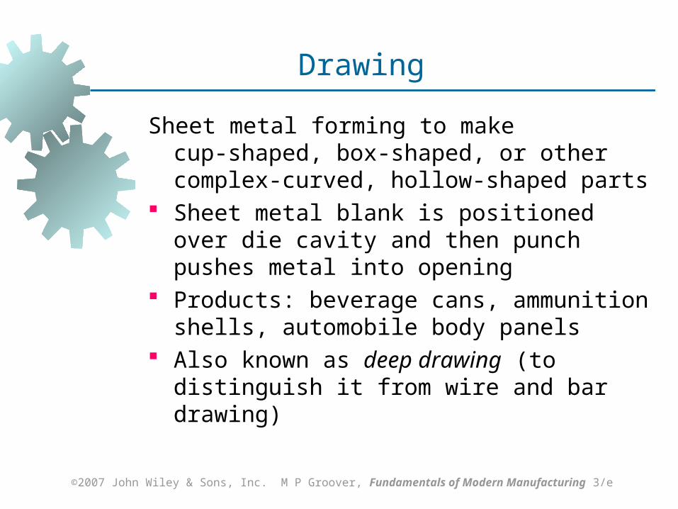
Sheet metal forming to make cup‑shaped, box‑shaped, or other complex‑curved, hollow‑shaped parts
Sheet metal blank is positioned over die cavity and then punch pushes metal into opening
Products: beverage cans, ammunition shells, automobile body panels
Also known as deep drawing (to distinguish it from wire and bar drawing)

©2007 John Wiley & Sons, Inc. M P Groover, Fundamentals of Modern Manufacturing 3/e
Figure 20.19 (a) Drawing of cup‑shaped part: (1) before punch contacts work, (2) near end of stroke; (b) workpart: (1) starting blank, (2) drawn part.
Drawing
©2007 John Wiley & Sons, Inc. M P Groover, Fundamentals of Modern Manufacturing 3/e
Clearance in Drawing
Sides of punch and die separated by a clearance c given by:
c = 1.1 t
where t = stock thickness In other words, clearance is about 10% greater
than stock thickness
©2007 John Wiley & Sons, Inc. M P Groover, Fundamentals of Modern Manufacturing 3/e
Shapes other than Cylindrical Cups
Square or rectangular boxes (as in sinks), Stepped cups Cones Cups with spherical rather than flat bases Irregular curved forms (as in automobile body
panels)
Each of these shapes presents its own unique technical problems in drawing

©2007 John Wiley & Sons, Inc. M P Groover, Fundamentals of Modern Manufacturing 3/e
Dies for Sheet Metal Processes
Most pressworking operations performed with conventional punch‑and‑die tooling
Custom‑designed for particular part The term stamping die sometimes used for
high production dies
©2007 John Wiley & Sons, Inc. M P Groover, Fundamentals of Modern Manufacturing 3/e
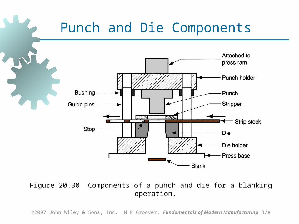
Figure 20.30 Components of a punch and die for a blanking operation.
Punch and Die Components

©2007 John Wiley & Sons, Inc. M P Groover, Fundamentals of Modern Manufacturing 3/e
Figure 20.31 (a) Progressive die; (b) associated strip development
Progressive Die
©2007 John Wiley & Sons, Inc. M P Groover, Fundamentals of Modern Manufacturing 3/e
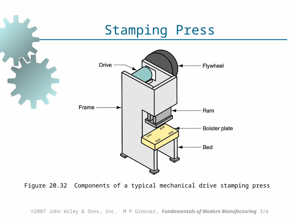
Figure 20.32 Components of a typical mechanical drive stamping press
Stamping Press

©2007 John Wiley & Sons, Inc. M P Groover, Fundamentals of Modern Manufacturing 3/e
Figure 20.33 Gap frame press for sheet metalworking (ohoto courtesy of E. W. Bliss Co.); capacity = 1350 kN (150 tons)

©2007 John Wiley & Sons, Inc. M P Groover, Fundamentals of Modern Manufacturing 3/e
Figure 20.34 Press brake (photo courtesy of Niagara Machine & Tool Works); bed width = 9.15 m (30 ft) and capacity = 11,200 kN (1250 tons).
©2007 John Wiley & Sons, Inc. M P Groover, Fundamentals of Modern Manufacturing 3/e
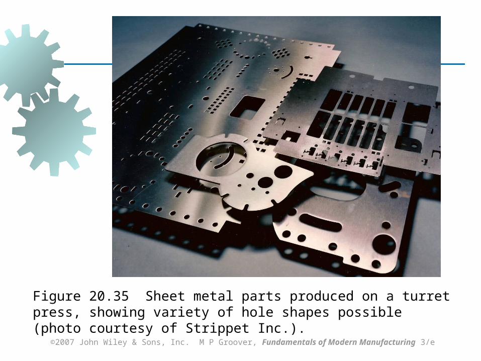
Figure 20.35 Sheet metal parts produced on a turret press, showing variety of hole shapes possible (photo courtesy of Strippet Inc.).
©2007 John Wiley & Sons, Inc. M P Groover, Fundamentals of Modern Manufacturing 3/e
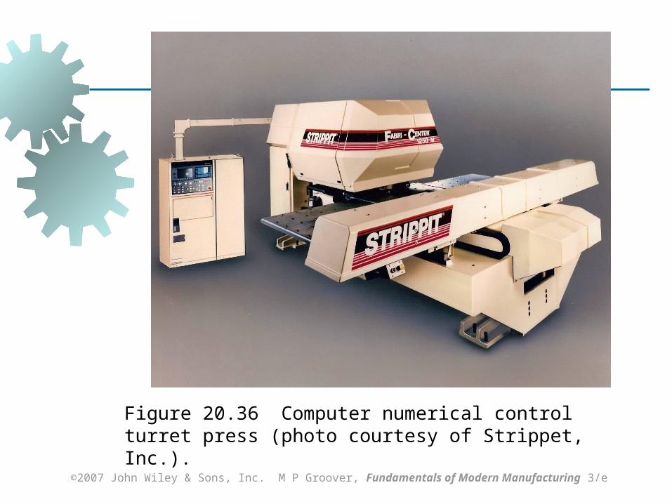
Figure 20.36 Computer numerical control turret press (photo courtesy of Strippet, Inc.).

©2007 John Wiley & Sons, Inc. M P Groover, Fundamentals of Modern Manufacturing 3/e
Figure 20.37
Straight‑sided frame press (photo courtesy of Greenerd Press & Machine Company, Inc.).

©2007 John Wiley & Sons, Inc. M P Groover, Fundamentals of Modern Manufacturing 3/e
Power and Drive Systems
Hydraulic presses - use a large piston and cylinder to drive the ram Longer ram stroke than mechanical types Suited to deep drawing Slower than mechanical drives
Mechanical presses – convert rotation of motor to linear motion of ram High forces at bottom of stroke Suited to blanking and punching