Chapter 6 Abstraction, Refinement, and - catalysis.orgcatalysis.org/books/ocf/ch06.pdf · Chapter 6...
72
213 Chapter 6 Abstraction, Refinement, and Testing Abstract diagrams are good for many purposes. At the whiteboard, you want to exhibit the main ideas of something without all the details of program code. Perhaps you want to say what it does and not how, or what it requires of other components that plug in to it. And whether it’s a single procedure or an entire planetwide distributed system, you want to fit it all on one board and convey useful things about it. When it comes to documentation, a component description that makes clear the essen- tial vision of your design will help future maintainers understand it quickly. Their short- order updates will more likely cohere with the rest of the design, thereby giving your bril- liant ideas a longer life. For users of the component (whether end users or other program- mers), you don’t want to show how the thing works inside but only what they can do with it. We have seen how to draw and write these abstract descriptions, but how can you be sure they accurately represent the code? The concepts of abstraction and refinement cap- ture the essential relationship between these descriptions. This chapter is about different forms of abstraction and refinement, and it explains the rules for showing that a more detailed model refines (or conforms to) a more abstract one. Refinement and conformance are a focal point in a Catalysis design review, in which you check that the design or implementation meets its specification(s). Testing fits naturally into this approach to abstraction and refinement. This chapter also discusses how to test different kinds of refinement relations, including the one between the implementation of an operation and its specification. You can read Sections 6.1 and 6.2 on a first pass, which touches all the main points.
Transcript of Chapter 6 Abstraction, Refinement, and - catalysis.orgcatalysis.org/books/ocf/ch06.pdf · Chapter 6...
Chapter 6 Abstraction, Refinement, and Testing
Abstract diagrams are good for many purposes. At the whiteboard, you want to exhibit themain ideas of something without all the details of program code. Perhaps you want to saywhat it does and not how, or what it requires of other components that plug in to it. Andwhether it’s a single procedure or an entire planetwide distributed system, you want to fitit all on one board and convey useful things about it.
When it comes to documentation, a component description that makes clear the essen-tial vision of your design will help future maintainers understand it quickly. Their short-order updates will more likely cohere with the rest of the design, thereby giving your bril-liant ideas a longer life. For users of the component (whether end users or other program-mers), you don’t want to show how the thing works inside but only what they can do withit.
We have seen how to draw and write these abstract descriptions, but how can you besure they accurately represent the code? The concepts of abstraction and refinement cap-ture the essential relationship between these descriptions. This chapter is about differentforms of abstraction and refinement, and it explains the rules for showing that a moredetailed model refines (or conforms to) a more abstract one.
Refinement and conformance are a focal point in a Catalysis design review, in whichyou check that the design or implementation meets its specification(s).
Testing fits naturally into this approach to abstraction and refinement. This chapter alsodiscusses how to test different kinds of refinement relations, including the one between theimplementation of an operation and its specification.
You can read Sections 6.1 and 6.2 on a first pass, which touches all the main points.
213
214 PART III FACTORING MODELS AND DESIGNS
6.1 Zooming In and Out: Why Abstract and Refine?
A major theme of Catalysis is precise abstraction: the ability to look at a design or a modelin only as much detail as necessary and without loss of precision. You can preciselydescribe your code to your colleagues in documents or in presentations, or just sketchingover coffee, without getting into superfluous detail. The abstract views can isolate differ-ent concerns; you can present the behavior of a component from the point of view of a par-ticular user (or of another component) omitting details seen by another user (or throughanother interface). You can restrict yourself to the externally visible behavior, or you candescribe the internal design scheme. You can describe only one component, a partial col-laboration pattern, or the way the components fit together; or you can describe architec-tural rules followed by all the components.
The zoomed-out, abstract views and the zoomed-in, detailed views must be clearlyrelated. If you write, “and we use the kwik-kache approach to cache information on theclient,” the link between this abstract intent and the code must be quite clear for it tosurvive the first few rounds of maintenance by new programmers.
Enter the refinement relation. Using it, you can tell whether the code for a componentconforms to the interface expected by its clients and whether a system, if designed tobehave as specified, would contribute to the business needs; you can also link individualrequirements to specific features of a design. All this gives you a much better start on whatis the real long-term problem: change management.
The degree of rigor of this traceability is variable. In a critical context, you can do thesechecks in mathematical detail. In more ordinary circumstances, you document the mainpoints of correspondence to guide reviewers and maintainers and use these points as thebasis for verification, design reviews, and testing.
Testing of object and component designs can be more difficult than in traditional sys-tems because of the added complication of polymorphism, inheritance, and arbitrary over-riding of behaviors. The essential idea of testing is to verify that an implementation meetsits specification—the same goal as that of refinement except that testing tackles the prob-lem by monitoring runtime behaviors under a systematically derived set of test cases. Thischapter outlines a systematic test approach based on refinement.
© abstraction (1) A description of something that omits some details that are not relevant to
the purpose of the abstraction; the converse of refinement. Types, collaborations, and action
specs are different kinds of abstractions.(2) To abstract (verb) is to create an abstraction; also called generalize, specify, and
sometimes analyze.
© refinement (1) A detailed description that conforms to another (its abstraction). Everything
said about the abstraction holds, perhaps in a somewhat different form, in the refinement. Also called realization.
(2) The relationship between the abstract and detailed descriptions.
Chapter 6 Abstractions, Refinement, and Testing 215
(3) To refine (verb) is to create a refinement; also called design, implement, or specialize.
© conformance One behavioral description conforms to another if (and only if) any object that behaves as described by one also behaves as described by the other (given a mapping
between the two descriptions). A conformance is a relationship between the two descrip-tions, accompanied by a justification that includes the mapping between them and the ratio-nale for the choices made. Refinement and conformance form the basis of traceability and
document the answer to the “why” question: Why is this design done this way?
© retrieval A function that determines the value of an abstract attribute from the stored imple-mentation data (or otherwise detailed attributes); used with a conformance to show how the
attributes map to the abstraction as a prerequisite to showing how the behavior specifications
are also met.
© implementation Program code that conforms to an abstraction; requires no further refine-ment (strictly speaking, it still goes through compilation and the like).
© testing The activity of uncovering defects in an implementation by comparing its behavior against that of its specification under a given set of runtime stimuli (the test cases or test data).
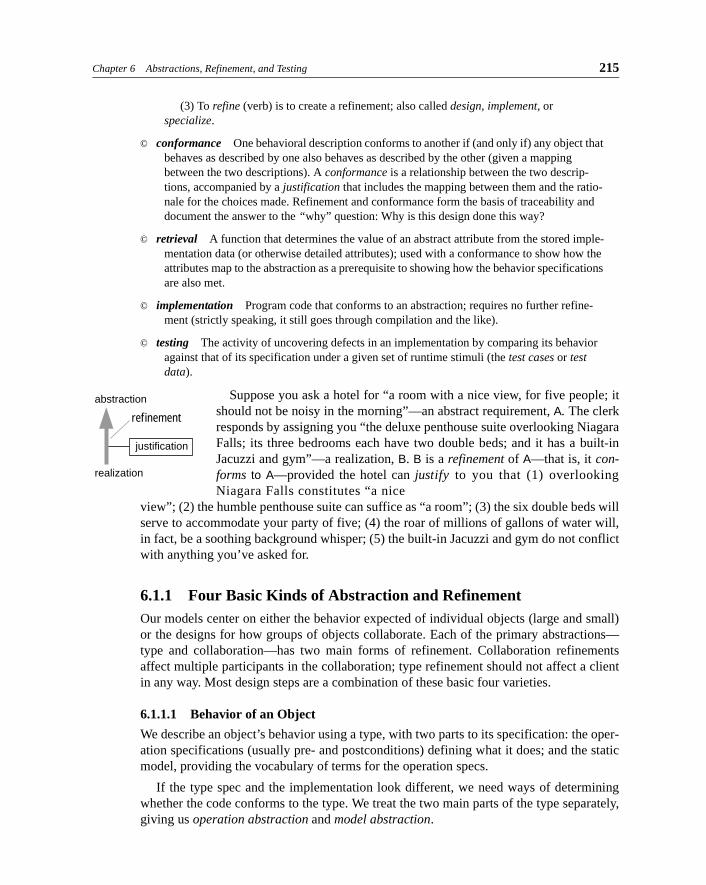
Suppose you ask a hotel for “a room with a nice view, for five people; itshould not be noisy in the morning”—an abstract requirement, A. The clerkresponds by assigning you “the deluxe penthouse suite overlooking NiagaraFalls; its three bedrooms each have two double beds; and it has a built-inJacuzzi and gym”—a realization, B. B is a refinement of A—that is, it con-forms to A—provided the hotel can justify to you that (1) overlookingNiagara Falls constitutes “a nice
view”; (2) the humble penthouse suite can suffice as “a room”; (3) the six double beds willserve to accommodate your party of five; (4) the roar of millions of gallons of water will,in fact, be a soothing background whisper; (5) the built-in Jacuzzi and gym do not conflictwith anything you’ve asked for.
6.1.1 Four Basic Kinds of Abstraction and RefinementOur models center on either the behavior expected of individual objects (large and small)or the designs for how groups of objects collaborate. Each of the primary abstractions—type and collaboration—has two main forms of refinement. Collaboration refinementsaffect multiple participants in the collaboration; type refinement should not affect a clientin any way. Most design steps are a combination of these basic four varieties.
6.1.1.1 Behavior of an Object
We describe an object’s behavior using a type, with two parts to its specification: the oper-ation specifications (usually pre- and postconditions) defining what it does; and the staticmodel, providing the vocabulary of terms for the operation specs.
If the type spec and the implementation look different, we need ways of determiningwhether the code conforms to the type. We treat the two main parts of the type separately,giving us operation abstraction and model abstraction.
refinement
abstraction
justification
realization
216 PART III FACTORING MODELS AND DESIGNS
An operation spec (and a static model) is a bit like the usage instructions for a machine(with a simplified drawing of the machine): It tells us what to expect as users. But if weremove the top from the machine, we may see a more complicated mechanism at work.The same thing happens when we look at the implementation code that meets a type spec:Its stored data, variable names, and specific sequences of statements are not seen from theoutside.
6.1.1.2 Collaborations among Objects
We describe designs for objects using collaborations—collections of actions. A jointaction defines a goal achieved collaboratively between the participant objects, using post-conditions whose vocabulary is the model of each of the participants. Collaborations rangefrom business interactions (“banks trade stocks”) to hardware (“fax sender sends docu-ment to receiver”) to software (“scrollbar displays file position”).
An abstract action spec states only the goal achieved and the participants it affects. Butwe can put more detail into the design by working out a protocol of interactions betweenthe participants. Such refinements might include banks make deals, confirm deals, settlethe accounts; fax connects, sends page, confirms, repeats; file notifies scrollbar of changeof position.
Similarly, we may discover that each of the participants is itself an abstraction made upof distinct parts that play roles in the collaboration. The banks’ traders make the deal, buttheir back offices do the settlement. Again, the two aspects of the collaboration can betreated separately, giving action abstraction and object abstraction.
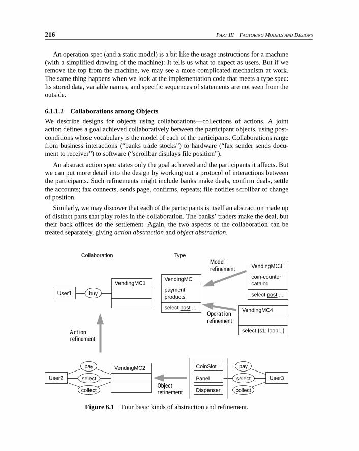
Figure 6.1 Four basic kinds of abstraction and refinement.
Modelrefinement
Operationrefinement
Collaboration Type
VendingMC1
User1
VendingMC4
select {s1; loop;..}
VendingMC
paymentproducts
select post ...
VendingMC3
coin-countercatalog
select post ...buy
VendingMC2
User2
CoinSlot
Panel
Dispensercollect
select
Actionrefinement
Objectrefinement
pay
User3
collect
select
pay
Chapter 6 Abstractions, Refinement, and Testing 217
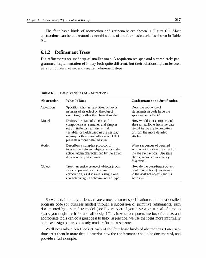
The four basic kinds of abstraction and refinement are shown in Figure 6.1. Mostabstractions can be understood as combinations of the four basic varieties shown in Table6.1.
6.1.2 Refinement TreesBig refinements are made up of smaller ones. A requirements spec and a completely pro-grammed implementation of it may look quite different, but their relationship can be seenas a combination of several smaller refinement steps.
Table 6.1 Basic Varieties of Abstractions
Abstraction What It Does Conformance and Justification
Operation Specifies what an operation achieves Does the sequence ofin terms of its effect on the object statements in code have theexecuting it rather than how it works specified net effect?
Model Defines the state of an object (or How would you compute eachcomponent) as a smaller and simpler abstract attribute from the dataset of attributes than the actual stored in the implementation,variables or fields used in the design; or from the more detailedor simpler than some other model that attributes?presents a more detailed view.
Action Describes a complex protocol of What sequences of detailedinteraction between objects as a single actions will realize the effect ofaction, again characterized by the effect the abstract action? Use state it has on the participants. charts, sequence or activity
diagrams.
Object Treats an entire group of objects (such How do the constituent objectsas a component or subsystem or (and their actions) correspondcorporation) as if it were a single one, to the abstract object (and itscharacterizing its behavior with a type. actions)?
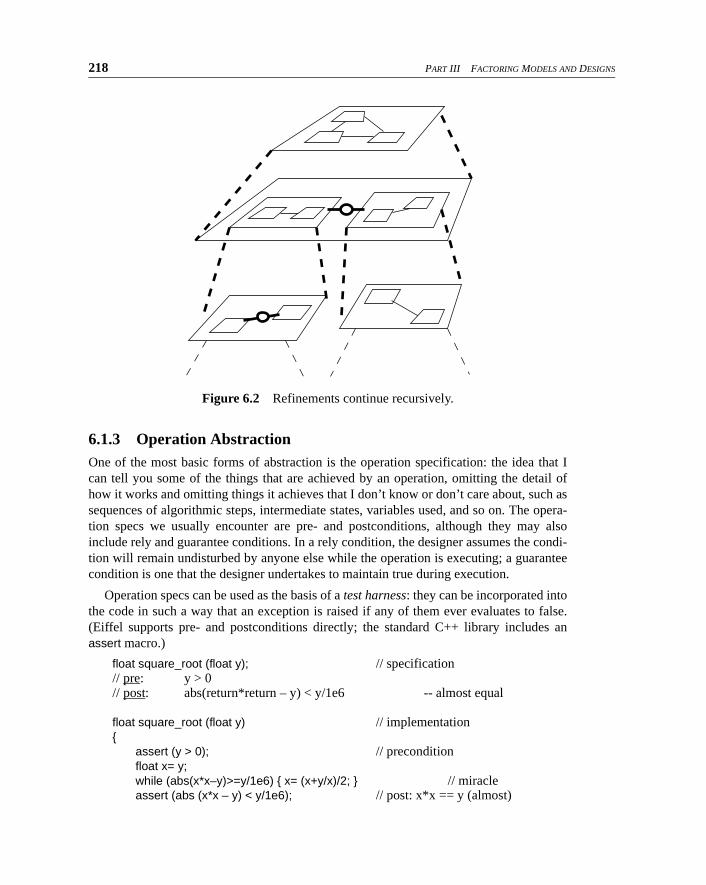
So we can, in theory at least, relate a most abstract specification to the most detailedprogram code (or business model) through a succession of primitive refinements, eachdocumented by a complete model (see Figure 6.2). If you have a great deal of time tospare, you might try it for a small design! This is what computers are for, of course, andappropriate tools can do a great deal to help. In practice, we use the ideas more informallyand use design patterns as ready-made refinement schemes.
We’ll now take a brief look at each of the four basic kinds of abstractions. Later sec-tions treat them in more detail, describe how the conformance should be documented, andprovide a full example.
218 PART III FACTORING MODELS AND DESIGNS
6.1.3 Operation AbstractionOne of the most basic forms of abstraction is the operation specification: the idea that Ican tell you some of the things that are achieved by an operation, omitting the detail ofhow it works and omitting things it achieves that I don’t know or don’t care about, such assequences of algorithmic steps, intermediate states, variables used, and so on. The opera-tion specs we usually encounter are pre- and postconditions, although they may alsoinclude rely and guarantee conditions. In a rely condition, the designer assumes the condi-tion will remain undisturbed by anyone else while the operation is executing; a guaranteecondition is one that the designer undertakes to maintain true during execution.
Operation specs can be used as the basis of a test harness: they can be incorporated intothe code in such a way that an exception is raised if any of them ever evaluates to false.(Eiffel supports pre- and postconditions directly; the standard C++ library includes anassert macro.)
float square_root (float y); // specification// pre: y > 0// post: abs(return*return – y) < y/1e6 -- almost equal
float square_root (float y) // implementation{
assert (y > 0); // preconditionfloat x= y;while (abs(x*x–y)>=y/1e6) { x= (x+y/x)/2; } // miracleassert (abs (x*x – y) < y/1e6); // post: x*x == y (almost)
Figure 6.2 Refinements continue recursively.
Chapter 6 Abstractions, Refinement, and Testing 219
return x; }
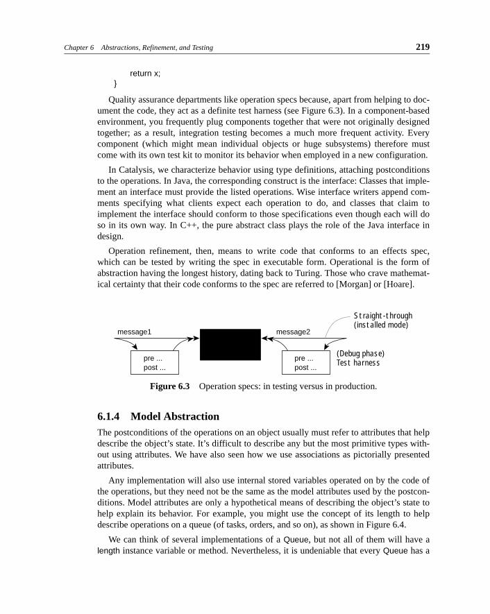
Quality assurance departments like operation specs because, apart from helping to doc-ument the code, they act as a definite test harness (see Figure 6.3). In a component-basedenvironment, you frequently plug components together that were not originally designedtogether; as a result, integration testing becomes a much more frequent activity. Everycomponent (which might mean individual objects or huge subsystems) therefore mustcome with its own test kit to monitor its behavior when employed in a new configuration.
In Catalysis, we characterize behavior using type definitions, attaching postconditionsto the operations. In Java, the corresponding construct is the interface: Classes that imple-ment an interface must provide the listed operations. Wise interface writers append com-ments specifying what clients expect each operation to do, and classes that claim toimplement the interface should conform to those specifications even though each will doso in its own way. In C++, the pure abstract class plays the role of the Java interface indesign.
Operation refinement, then, means to write code that conforms to an effects spec,which can be tested by writing the spec in executable form. Operational is the form ofabstraction having the longest history, dating back to Turing. Those who crave mathemat-ical certainty that their code conforms to the spec are referred to [Morgan] or [Hoare].
6.1.4 Model AbstractionThe postconditions of the operations on an object usually must refer to attributes that helpdescribe the object’s state. It’s difficult to describe any but the most primitive types with-out using attributes. We have also seen how we use associations as pictorially presentedattributes.
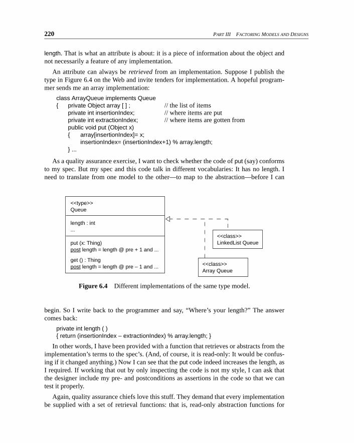
Any implementation will also use internal stored variables operated on by the code ofthe operations, but they need not be the same as the model attributes used by the postcon-ditions. Model attributes are only a hypothetical means of describing the object’s state tohelp explain its behavior. For example, you might use the concept of its length to helpdescribe operations on a queue (of tasks, orders, and so on), as shown in Figure 6.4.
We can think of several implementations of a Queue, but not all of them will have alength instance variable or method. Nevertheless, it is undeniable that every Queue has a
Figure 6.3 Operation specs: in testing versus in production.
Straight-through(installed mode)
(Debug phase)Test harness
message1 message2
pre ... post ...
pre ... post ...
220 PART III FACTORING MODELS AND DESIGNS
length. That is what an attribute is about: it is a piece of information about the object andnot necessarily a feature of any implementation.
An attribute can always be retrieved from an implementation. Suppose I publish thetype in Figure 6.4 on the Web and invite tenders for implementation. A hopeful program-mer sends me an array implementation:
class ArrayQueue implements Queue{ private Object array [ ] ; // the list of items
private int insertionIndex; // where items are putprivate int extractionIndex; // where items are gotten frompublic void put (Object x){ array[insertionIndex]= x;
insertionIndex= (insertionIndex+1) % array.length; } ...
As a quality assurance exercise, I want to check whether the code of put (say) conformsto my spec. But my spec and this code talk in different vocabularies: It has no length. Ineed to translate from one model to the other—to map to the abstraction—before I can
begin. So I write back to the programmer and say, “Where’s your length?” The answercomes back:
private int length ( ) { return (insertionIndex – extractionIndex) % array.length; }
In other words, I have been provided with a function that retrieves or abstracts from theimplementation’s terms to the spec’s. (And, of course, it is read-only: It would be confus-ing if it changed anything.) Now I can see that the put code indeed increases the length, asI required. If working that out by only inspecting the code is not my style, I can ask thatthe designer include my pre- and postconditions as assertions in the code so that we cantest it properly.
Again, quality assurance chiefs love this stuff. They demand that every implementationbe supplied with a set of retrieval functions: that is, read-only abstraction functions for
Figure 6.4 Different implementations of the same type model.
<<type>>
Queue
length : int ...
put (x: Thing) post length = length @ pre + 1 and ...
<<class>>
Array Queue
<<class>>
LinkedList Queue
get () : Thing
post length = length @ pre – 1 and ...
Chapter 6 Abstractions, Refinement, and Testing 221
computing the value of every attribute in the abstract spec. This also applies to associa-tions, which we have previously observed are merely pictorial presentations of attributes.
Another implementation of a queue is based on a linked list. There is not necessarilyany variable that corresponds directly to the model’s length, but you can retrieve it bycounting the nodes.
It doesn’t matter whether retrieval functions are slow and inefficient: They are requiredonly for verification either by testing or by reasoning. The exercise of writing them oftenexposes mistakes in an implementation when the designer realizes that a vital piece ofinformation is missing.
Notice that in Catalysis, we do not expect that attributes and associations will always bepublicly supplied for use by clients. There are, of course, many attributes to which it is usefulfor clients to have “get” and sometimes “set” access; but modelers often use attributes toexpress intermediate information they don’t expect to be available directly to clients.
On a larger scale, more-complex models can be used to represent the types of wholesystems or components and are usually shown pictorially. In an abstract model, theattributes and their types are chosen to help specify the operations on the component as awhole and, according to good object-oriented analysis practice, are based on a model ofthe domain. However, anyone who has been involved in practical OOD is aware that thedesign phase introduces all sorts of extra classes as patterns are applied to help generalizethe design, make it more efficient, distribute the design, provide persistence or a GUI, andso on. But we can still retrieve the abstract model from any true implementation in thesame way as for the simpler models.
Model refinement, then, means to establish the relationship between the more abstractmodel used to define postconditions and the more complex practical implementation.Retrieve functions translate from the refined model attributes to the abstract ones.
Model refinement has the second longest history, dating back to VDM and Z in the1970s.
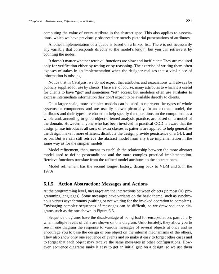
6.1.5 Action Abstraction: Messages and ActionsAt the programming level, messages are the interactions between objects (in most OO pro-gramming languages). Some messages have variants on the basic theme, such as synchro-nous versus asynchronous (waiting or not waiting for the invoked operation to complete).Envisaging complex sequences of messages can be difficult, so we draw sequence dia-grams such as the one shown in Figure 6.5.
Sequence diagrams have the disadvantage of being bad for encapsulation, particularlywhen multiple levels of calls are shown on one diagram. Unfortunately, they allow you tosee in one diagram the response to various messages of several objects at once and soencourage you to base the design of one object on the internal mechanisms of the others.They also show only one sequence of events and so make it easy to forget other cases andto forget that each object may receive the same messages in other configurations. How-ever, sequence diagrams make it easy to get an initial grip on a design, so we use them
222 PART III FACTORING MODELS AND DESIGNS
with caution. It is often good practice to limit the diagram to only one level of nesting andto use postconditions to understand what those events achieve.
The same diagrams can be used to show the interactions between objects in the busi-ness world and interactions between large components.
But in any but the most detailed level of design, we usually deal in actions: dialog withan outcome definable with a postcondition but made up of messages we do not care about.For example, I might tell you, “I bought some coffee” rather than expect you to listen to along tale about how I approached a vending machine, inserted several coins, pressed oneof the selector buttons, and so on. The former statement abstracts the latter detailedsequence and includes any other means of achieving the same effects. In Catalysis, actionsare characterized principally by their effects; to show how an action is achieved by somecombination of smaller ones, you document a refinement.
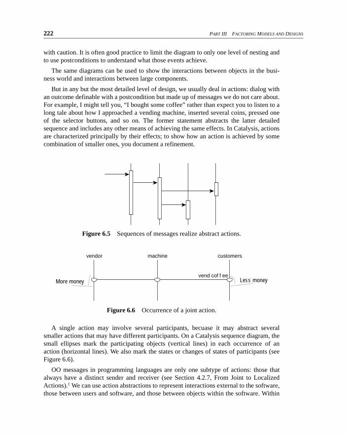
A single action may involve several participants, becuase it may abstract severalsmaller actions that may have different participants. On a Catalysis sequence diagram, thesmall ellipses mark the participating objects (vertical lines) in each occurrence of anaction (horizontal lines). We also mark the states or changes of states of participants (seeFigure 6.6).
OO messages in programming languages are only one subtype of actions: those thatalways have a distinct sender and receiver (see Section 4.2.7, From Joint to LocalizedActions).1 We can use action abstractions to represent interactions external to the software,those between users and software, and those between objects within the software. Within
Figure 6.5 Sequences of messages realize abstract actions.
Figure 6.6 Occurrence of a joint action.
Less moneyMore money
vendor machine customers
vend cof f ee
Chapter 6 Abstractions, Refinement, and Testing 223
the software, action abstractions are very useful for abstracting the standard interactionsthat happen within certain frameworks and patterns, such as observer.
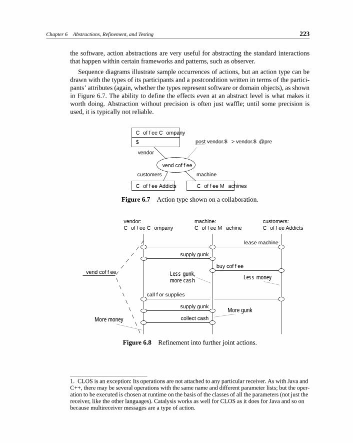
Sequence diagrams illustrate sample occurrences of actions, but an action type can bedrawn with the types of its participants and a postcondition written in terms of the partici-pants’ attributes (again, whether the types represent software or domain objects), as shownin Figure 6.7. The ability to define the effects even at an abstract level is what makes itworth doing. Abstraction without precision is often just waffle; until some precision isused, it is typically not reliable.
1. CLOS is an exception: Its operations are not attached to any particular receiver. As with Java and C++, there may be several operations with the same name and different parameter lists; but the oper-ation to be executed is chosen at runtime on the basis of the classes of all the parameters (not just the receiver, like the other languages). Catalysis works as well for CLOS as it does for Java and so on because multireceiver messages are a type of action.
Figure 6.7 Action type shown on a collaboration.
Figure 6.8 Refinement into further joint actions.
vendor
vend cof f ee
C of f ee C ompany
$
C of f ee Addicts C of f ee M achines
customers machine
post vendor.$ > vendor.$ @pre
Less gunk,more cash Less money
vendor:C of f ee C ompany
machine:C of f ee M achine
customers:C of f ee Addicts
lease machine
supply gunk
buy cof f ee
call f or supplies
supply gunk
collect cash
vend cof f ee
More moneyMore gunk
224 PART III FACTORING MODELS AND DESIGNS
6.1.5.1 Refining Actions
We can zoom into, or refine, the action to see more detail. What was one action is nowseen to be composed of several actions (see Figure 6.8). Each of these actions can be splitagain into smaller ones, into as much detail as you like. Some of the actions might be per-formed by software; others might be performed by some mixture of software, hardware,and people; still others might be the interactions between those things. At any level—deepinside the software or at the overall business level—we can treat them the same way.Catalysis is a “fractal” method: It works in the same way at any scale.
Notice that the abstract action has not gone away; we have only filled in more detail. Itis still the name we give to the accomplishment of a particular effect by a combination ofsmaller actions, and that effect is still there.
These illustrations might suggest that an action is always made up of a sequence, butoften the composition is of several concurrent processes that interact in some way. Recallthat action is the Catalysis blanket word for process, activity, task, function, subroutine,message, operation, and so on.
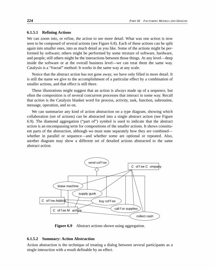
We can summarize any kind of action abstraction on a type diagram, showing whichcollaboration (set of actions) can be abstracted into a single abstract action (see Figure6.9). The diamond aggregation (“part of”) symbol is used to indicate that the abstractaction is an encompassing term for compositions of the smaller actions. It shows constitu-ent parts of the abstraction, although we must state separately how they are combined—whether in parallel or sequence—and whether some are optional or repeated. Also,another diagram may show a different set of detailed actions abstracted to the sameabstract action.
6.1.5.2 Summary: Action Abstraction
Action abstraction is the technique of treating a dialog between several participants as asingle interaction with a result definable by an effect.
Figure 6.9 Abstract actions shown using aggregation.
vend cof f ee
lease machine
C of f ee C ompany
C of f ee Addicts
C of f ee M achine
supply gunk
buy cof f ee
call f or supplies
collect cash
Chapter 6 Abstractions, Refinement, and Testing 225
Action abstraction and operation abstraction are both about treating several smalleractions as one. The differences can be summarized as follows.
• In operation abstraction, the initial invocation results in a sequence of smaller actions
determined by the design; the abstraction still has the same initial invocation and cap-tures the net desired effect.
• In action abstraction, no invoker need be identified: Any participant can initiate it. The
exact sequence is determined by the designs of all participants (some of whom could be
human); we can say only what the smaller actions are and the constraints on how they
might be combined. Also, the abstract action may never be directly “invoked” at the
detailed level.
Action abstraction comes from the idea of transaction, developed in the database world inthe 1970s, although it is a natural usage in everyday conversation.
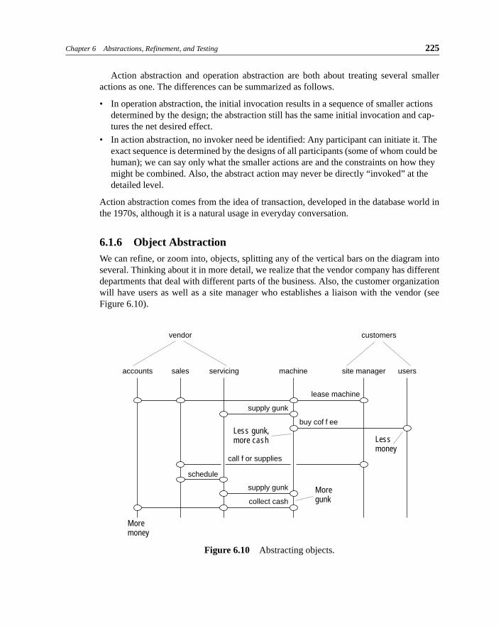
6.1.6 Object AbstractionWe can refine, or zoom into, objects, splitting any of the vertical bars on the diagram intoseveral. Thinking about it in more detail, we realize that the vendor company has differentdepartments that deal with different parts of the business. Also, the customer organizationwill have users as well as a site manager who establishes a liaison with the vendor (seeFigure 6.10).
Figure 6.10 Abstracting objects.
Less gunk,more cash Less
money
lease machine
supply gunk
buy cof f ee
call f or supplies
schedule
accounts sales
vendor
servicing machine site manager
customers
users
supply gunk
collect cash
Moremoney
Moregunk
226 PART III FACTORING MODELS AND DESIGNS
Again, the more-abstract objects have not gone away. The company is still there; it iswhat we call a particular configuration of interrelated smaller objects. Again, each objectcan be split further into smaller parts: servicing may turn out to be a department full ofpeople having various smaller roles.
Just as what characterizes an action is its effect, so what characterizes an object is theset of actions it takes part in—its type. There may be many refinements that will satisfyone abstract object type. (Indeed, there may be refinements that successfully satisfy sev-eral roles: Some small companies have only a single object that plays the roles ofaccounts, sales, and servicing.)
Some of the objects may be software components. For example, zooming in on theAccounts department would probably reveal some combination of people and computers,and more detail on the computers would reveal a configuration of software packages, andgoing into them would reveal lines of Cobol or, if we’re lucky, objects in an OO language.The same thing would happen if we peered into the coffee vending machine. And we cancontinue using the same interaction sequence diagrams (and other tools) right down intothe software.
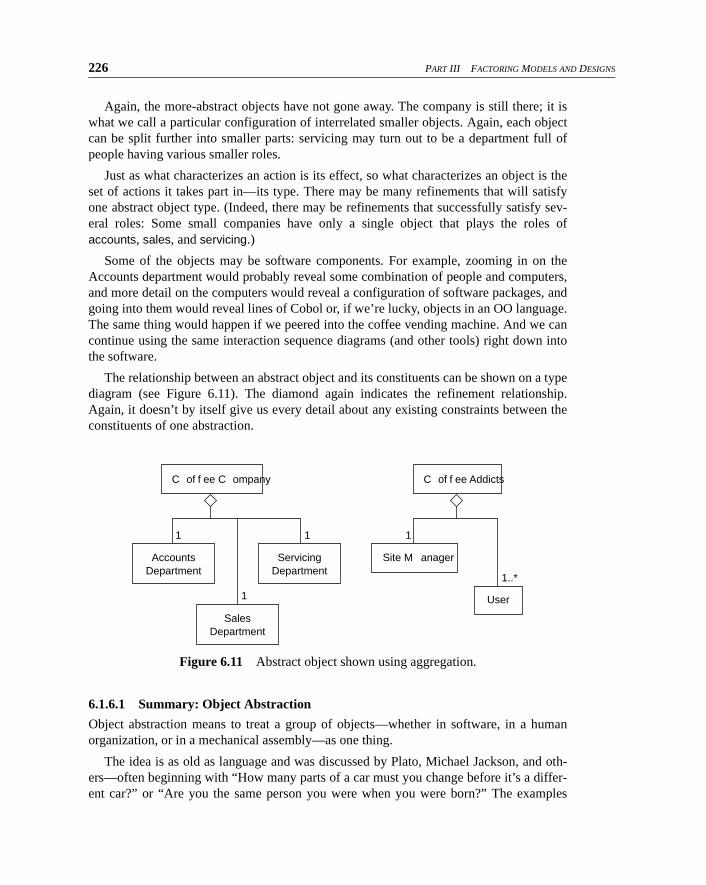
The relationship between an abstract object and its constituents can be shown on a typediagram (see Figure 6.11). The diamond again indicates the refinement relationship.Again, it doesn’t by itself give us every detail about any existing constraints between theconstituents of one abstraction.
6.1.6.1 Summary: Object Abstraction
Object abstraction means to treat a group of objects—whether in software, in a humanorganization, or in a mechanical assembly—as one thing.
The idea is as old as language and was discussed by Plato, Michael Jackson, and oth-ers—often beginning with “How many parts of a car must you change before it’s a differ-ent car?” or “Are you the same person you were when you were born?” The examples
Figure 6.11 Abstract object shown using aggregation.
C of f ee C ompany
Accounts
DepartmentServicing
Department
Sales
Department
1 1
1
C of f ee Addicts
Site M anager
User
1
1..*
Chapter 6 Abstractions, Refinement, and Testing 227
serve to highlight the idea that the identity of anything is, in the end, a model constructedfor our convenience rather than something inherent.
6.1.6.2 Abstracting Objects and Actions Together
It is usual to zoom in or out in both dimensions at the same time. As soon as you resolveeach object into several, you must introduce interactions specifically with or betweenthem. Conversely, when you put more detail into an action, you need more objects to rep-resent the intermediate states between the actions.
When we looked inside the vendor company, we assigned sales to receive supplyrequests from the customers, who then schedule a visit by servicing.
By contrast, we left the collection of cash as one action involving both servicing andaccounts. This means that we’ve deferred until later a decision about how that action splitsinto smaller steps.
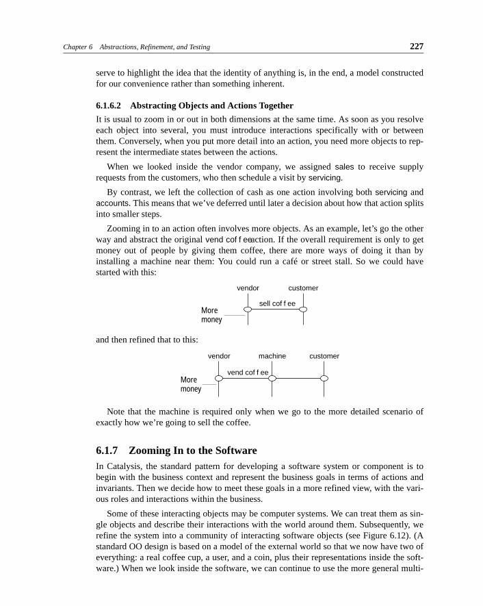
Zooming in to an action often involves more objects. As an example, let’s go the otherway and abstract the original vend cof f ee action. If the overall requirement is only to getmoney out of people by giving them coffee, there are more ways of doing it than byinstalling a machine near them: You could run a café or street stall. So we could havestarted with this:
and then refined that to this:
Note that the machine is required only when we go to the more detailed scenario ofexactly how we’re going to sell the coffee.
6.1.7 Zooming In to the SoftwareIn Catalysis, the standard pattern for developing a software system or component is tobegin with the business context and represent the business goals in terms of actions andinvariants. Then we decide how to meet these goals in a more refined view, with the vari-ous roles and interactions within the business.
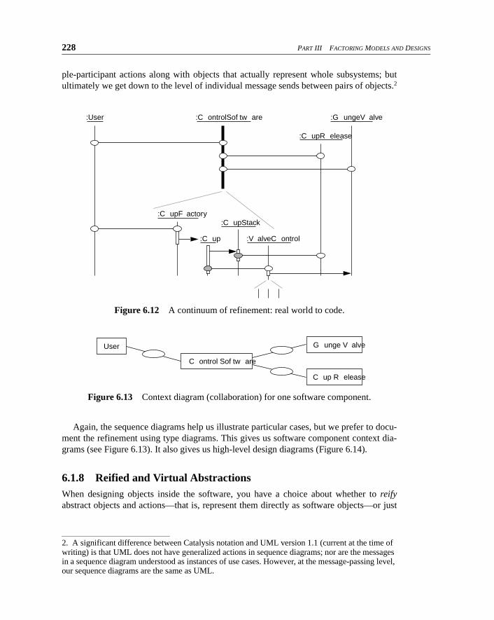
Some of these interacting objects may be computer systems. We can treat them as sin-gle objects and describe their interactions with the world around them. Subsequently, werefine the system into a community of interacting software objects (see Figure 6.12). (Astandard OO design is based on a model of the external world so that we now have two ofeverything: a real coffee cup, a user, and a coin, plus their representations inside the soft-ware.) When we look inside the software, we can continue to use the more general multi-
Moremoney
vendor customer
sell cof f ee
Moremoney
vendor machine customer
vend cof f ee
228 PART III FACTORING MODELS AND DESIGNS
ple-participant actions along with objects that actually represent whole subsystems; butultimately we get down to the level of individual message sends between pairs of objects.2
Again, the sequence diagrams help us illustrate particular cases, but we prefer to docu-ment the refinement using type diagrams. This gives us software component context dia-grams (see Figure 6.13). It also gives us high-level design diagrams (Figure 6.14).
6.1.8 Reified and Virtual AbstractionsWhen designing objects inside the software, you have a choice about whether to reifyabstract objects and actions—that is, represent them directly as software objects—or just
Figure 6.12 A continuum of refinement: real world to code.
Figure 6.13 Context diagram (collaboration) for one software component.
2. A significant difference between Catalysis notation and UML version 1.1 (current at the time of writing) is that UML does not have generalized actions in sequence diagrams; nor are the messages in a sequence diagram understood as instances of use cases. However, at the message-passing level, our sequence diagrams are the same as UML.
:User :C ontrolSof tw are :G ungeV alve
:C upR elease
:C upF actory:C upStack
:C up :V alveC ontrol
C ontrol Sof tw are
User G unge V alve
C up R elease
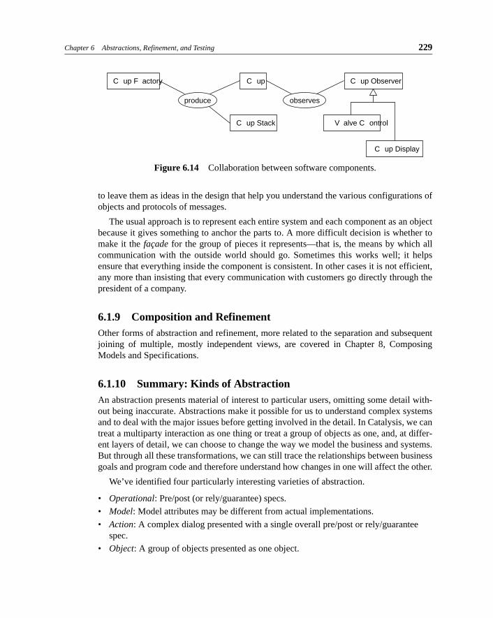
Chapter 6 Abstractions, Refinement, and Testing 229
to leave them as ideas in the design that help you understand the various configurations ofobjects and protocols of messages.
The usual approach is to represent each entire system and each component as an objectbecause it gives something to anchor the parts to. A more difficult decision is whether tomake it the façade for the group of pieces it represents—that is, the means by which allcommunication with the outside world should go. Sometimes this works well; it helpsensure that everything inside the component is consistent. In other cases it is not efficient,any more than insisting that every communication with customers go directly through thepresident of a company.
6.1.9 Composition and RefinementOther forms of abstraction and refinement, more related to the separation and subsequentjoining of multiple, mostly independent views, are covered in Chapter 8, ComposingModels and Specifications.
6.1.10 Summary: Kinds of AbstractionAn abstraction presents material of interest to particular users, omitting some detail with-out being inaccurate. Abstractions make it possible for us to understand complex systemsand to deal with the major issues before getting involved in the detail. In Catalysis, we cantreat a multiparty interaction as one thing or treat a group of objects as one, and, at differ-ent layers of detail, we can choose to change the way we model the business and systems.But through all these transformations, we can still trace the relationships between businessgoals and program code and therefore understand how changes in one will affect the other.
We’ve identified four particularly interesting varieties of abstraction.
• Operational: Pre/post (or rely/guarantee) specs.
• Model: Model attributes may be different from actual implementations.
• Action: A complex dialog presented with a single overall pre/post or rely/guarantee
spec.
• Object: A group of objects presented as one object.
Figure 6.14 Collaboration between software components.
C up F actory
produce
C up Observer
C up Stack V alve C ontrol
C up Display
C up
observes
230 PART III FACTORING MODELS AND DESIGNS
6.2 Documenting Refinement and Conformance
When you write a requirements specification (in any style and language you like), youwant it to be a true statement about the product that ends up being delivered. If QA showsthat the product falls short of the spec, you fix the code; or if it turns out to be impracticalto deliver what was first specified, you can change the specification. But one way oranother, you can’t (or shouldn’t!) call the job complete until the delivered design matchesthe specified requirements.
For valuable components (as opposed to throwaway assemblages of them), we believe inkeeping the specification after you’ve written the code and in keeping it up-to-date. In the longrun, the spec (and high-level design documents) helps to keep the design coherent, becausepeople who do updates have a clearer idea of what the component is about and how it is sup-posed to work. Designs without good documents degenerate into fractal warts and patches andsoon end up unmodifiable. Remember that more than 70% of the effort on a typical piece ofsoftware is done after it is first delivered and consider whether you want your vision of thedesign to be long-lived.
This is not to argue that you should complete the high-level documentation beforeembarking on coding. There are plenty of times when it’s a tactical necessity to do thingsthe other way around. Prototypes and rapidly approaching deadlines are the usual reasons.The most useful cycle alternates between coding (to obtain feedback from testing andusers and to get things done) and specifying (to get overall insights). Never go beyond get-ting either cycle 80% complete without working on the other. All we need is that, by theappropriate milestone, the specs should correctly describe the code.
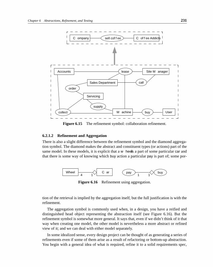
6.2.1 Documenting the Refinement RelationshipThe relationship between an abstraction and a refinement is the refinement relationship. Itis an assertion that one description of a configuration of objects and actions is a moreabstract view of another (see Figure 6.15).
6.2.1.1 Refinement and Subtype
The refinement symbol is a version of the subtype symbol.3 It states that the more detailedmodel achieves everything expected from the more abstract one. But whereas a subtypesymbol says to the reader, “The subtype is defined a priori as an extension of the super-type, having all its properties and more,” the refinement symbol says, “The refinement, aself-contained model even without the abstraction, is believed to specify everythingdefined for the abstraction and more.”
3. UML 1.1 makes mention of refinement, with a default notation that uses a stereotype on the generic ‘dependency’ arrow. Refinement is central to Catalysis; in our presentation here, we have chosen to highlight refinement with a distinguished arrow.
Chapter 6 Abstractions, Refinement, and Testing 231
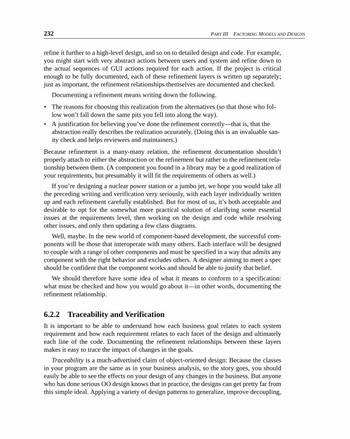
6.2.1.2 Refinement and Aggregation
There is also a slight difference between the refinement symbol and the diamond aggrega-tion symbol. The diamond makes the abstract and constituent types (or actions) part of thesame model. In these models, it is explicit that a w heel is a part of some particular car andthat there is some way of knowing which buy action a particular pay is part of; some por-
tion of the retrieval is implied by the aggregation itself, but the full justification is with therefinement.
The aggregation symbol is commonly used when, in a design, you have a reified anddistinguished head object representing the abstraction itself (see Figure 6.16). But therefinement symbol is somewhat more general. It says that, even if we didn’t think of it thatway when creating one model, the other model is nevertheless a more abstract or refinedview of it; and we can deal with either model separately.
In some idealized sense, every design project can be thought of as generating a series ofrefinements even if some of them arise as a result of refactoring or bottom-up abstraction.You begin with a general idea of what is required, refine it to a solid requirements spec,
Figure 6.15 The refinement symbol: collaboration refinement.
Figure 6.16 Refinement using aggregation.
C ompany sell cof f ee C of f ee Addicts
Accounts lease
order
call
collect
supply
Servicing
M achine User
Site M anager
Sales Department
buy
Wheel C ar4 1
pay buy1 1
232 PART III FACTORING MODELS AND DESIGNS
refine it further to a high-level design, and so on to detailed design and code. For example,you might start with very abstract actions between users and system and refine down tothe actual sequences of GUI actions required for each action. If the project is criticalenough to be fully documented, each of these refinement layers is written up separately;just as important, the refinement relationships themselves are documented and checked.
Documenting a refinement means writing down the following.
• The reasons for choosing this realization from the alternatives (so that those who fol-low won’t fall down the same pits you fell into along the way).
• A justification for believing you’ve done the refinement correctly—that is, that the
abstraction really describes the realization accurately. (Doing this is an invaluable san-ity check and helps reviewers and maintainers.)
Because refinement is a many-many relation, the refinement documentation shouldn’tproperly attach to either the abstraction or the refinement but rather to the refinement rela-tionship between them. (A component you found in a library may be a good realization ofyour requirements, but presumably it will fit the requirements of others as well.)
If you’re designing a nuclear power station or a jumbo jet, we hope you would take allthe preceding writing and verification very seriously, with each layer individually writtenup and each refinement carefully established. But for most of us, it’s both acceptable anddesirable to opt for the somewhat more practical solution of clarifying some essentialissues at the requirements level, then working on the design and code while resolvingother issues, and only then updating a few class diagrams.
Well, maybe. In the new world of component-based development, the successful com-ponents will be those that interoperate with many others. Each interface will be designedto couple with a range of other components and must be specified in a way that admits anycomponent with the right behavior and excludes others. A designer aiming to meet a specshould be confident that the component works and should be able to justify that belief.
We should therefore have some idea of what it means to conform to a specification:what must be checked and how you would go about it—in other words, documenting therefinement relationship.
6.2.2 Traceability and VerificationIt is important to be able to understand how each business goal relates to each systemrequirement and how each requirement relates to each facet of the design and ultimatelyeach line of the code. Documenting the refinement relationships between these layersmakes it easy to trace the impact of changes in the goals.
Traceability is a much-advertised claim of object-oriented design: Because the classesin your program are the same as in your business analysis, so the story goes, you shouldeasily be able to see the effects on your design of any changes in the business. But anyonewho has done serious OO design knows that in practice, the designs can get pretty far fromthis simple ideal. Applying a variety of design patterns to generalize, improve decoupling,
Chapter 6 Abstractions, Refinement, and Testing 233
and optimize performance, you separate the simple analysis concepts into a plethora ofdelegations, policies, factories, and plug-in pieces.
© traceability The ability to relate elements in a detailed description to the elements in an
abstraction that motivate their presence and vice versa; the ability to relate implementation
elements to requirements.
Documenting the refinement relationship puts back the traceability, showing how eachpiece of the analysis relates to the design.
In safety-critical systems, it is possible to document refinements precisely enough toperform automatic consistency checks on them. However, achieving this level of precisionis rarely cost-effective, and we do not deal with that topic in this book.
For the majority of projects, it is sufficient to use pre- and postconditions as the basis oftest harnesses and to document just enough of a refinement that other developers andmaintainers clearly see the design intent. We’ll see how to do that later in this chapter.
6.3 Spreadsheet: A Refinement Example
The sections that follow look in more detail at the four main kinds of refinement we men-tioned earlier. This section introduces an example that runs through those sections.
6.3.1 A Specification for a SpreadsheetLet’s look first at what can be done with a good abstract model. It’s a model of a self-con-tained program, but it could equally well be a component in a larger system.
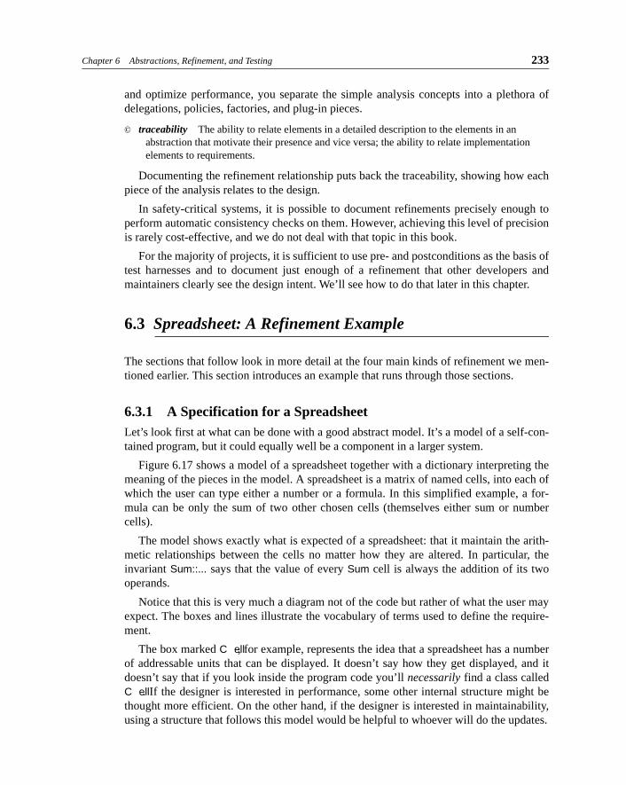
Figure 6.17 shows a model of a spreadsheet together with a dictionary interpreting themeaning of the pieces in the model. A spreadsheet is a matrix of named cells, into each ofwhich the user can type either a number or a formula. In this simplified example, a for-mula can be only the sum of two other chosen cells (themselves either sum or numbercells).
The model shows exactly what is expected of a spreadsheet: that it maintain the arith-metic relationships between the cells no matter how they are altered. In particular, theinvariant Sum::... says that the value of every Sum cell is always the addition of its twooperands.
Notice that this is very much a diagram not of the code but rather of what the user mayexpect. The boxes and lines illustrate the vocabulary of terms used to define the require-ment.
The box marked C ell, for example, represents the idea that a spreadsheet has a numberof addressable units that can be displayed. It doesn’t say how they get displayed, and itdoesn’t say that if you look inside the program code you’ll necessarily find a class calledC ell. If the designer is interested in performance, some other internal structure might bethought more efficient. On the other hand, if the designer is interested in maintainability,using a structure that follows this model would be helpful to whoever will do the updates.
234 PART III FACTORING MODELS AND DESIGNS
The model doesn’t even say everything that you could think of to say about the require-ments. For example, are the C ells arranged in any given order on the screen? How does theuser refer to a C ell when making a Sum? If not all the C ells will fit on the screen at a time,is there a scrolling mechanism?
Figure 6.17 Model for a spreadsheet.
Spreadsheet
Spreadsheet R equirements
C ell
Sum Number
Blank
inv Blank:: value = 0
show sC ontent
value
*
*
*
lef t right
content
1 1
inv
Sum :: value = lef t.content.value + right.content.value
setNumber(n) setSum(C ell, C ell)
User Spreadsheet Each instance is a collection of interrelated Cells.
shows Every Spreadsheet contains a collection of Cells. (Oftendisplayed in a two-dimensional matrix, but other arrange-ments are possible. We say nothing here about what theUser does to see the Cells.)
Cell Each instance is a displayable element that can bereferred to by the User (such as by name or pointing).
Content The information displayed in a Cell, which can be setby the User (by some means not defined here).
Number Each instance represents a Number entered into a Celldirectly by the User.
Sum Each instance represents a Sum of the content of twoother Cells determined by the User.
Blank The initial content of all the Cells of a new Sheet.
User, c:Cell Represents the ability of the User to set a Cell’s contentsetNumber(n : int) to be a Number.
Postcondition: Cell c’s content is a Number, with value= n.
User, c:Cell Represents the ability of the User to set a Cell’s contentsetSum(c1 : Cell, c2: Cell) to be the Sum of two other Cells.
Postcondition: Cell c’s content is a Sum whose left andright are the Cells c1 and c2.
Precondition: c is not a descendant of c1 or c2.
11
Chapter 6 Abstractions, Refinement, and Testing 235
It’s part of the utility of abstract modeling that you can say or not say as many of thesethings as you like. And you can be as precise or ambiguous as you like; we could have putthe {Sum::... invariant as a sentence in English. This facility for abstraction allows us touse modeling notation to focus on the matters of most interest.
6.3.1.1 Using Snapshots to Animate the Spec
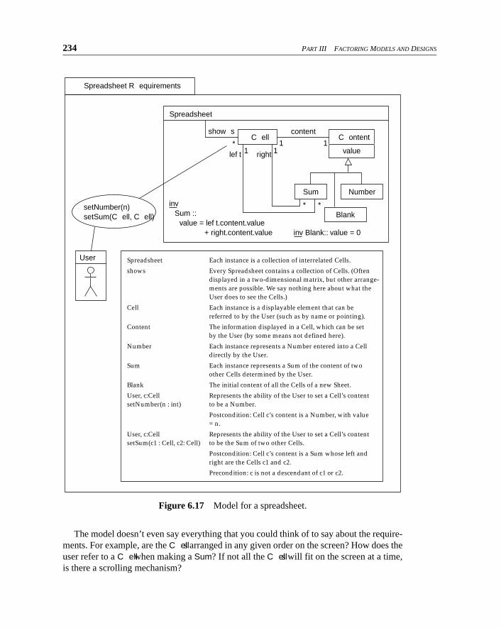
Although (or perhaps because) the model omits a lot of the details you’d see in the code,you can do useful things with it. For example, we can draw snapshots: instance diagramsthat illustrate clearly the effect each operation has.
Snapshots illustrate specific example situations. Figure 6.18 shows snapshots depictingthe state of our spreadsheet before and after an operation. (The thicker lines and bold typerepresent the state after the operation.) Notice that because we are dealing with a require-ments model here, we show no messages (function calls) between the objects; they will bedecided in the design process. Here we’re concerned only with the effects of the operationinvoked by the user. This is part of how the layering of decisions works in Catalysis: Westart with the effects of operations and then work out how they are implemented in termsof collaborations between objects.
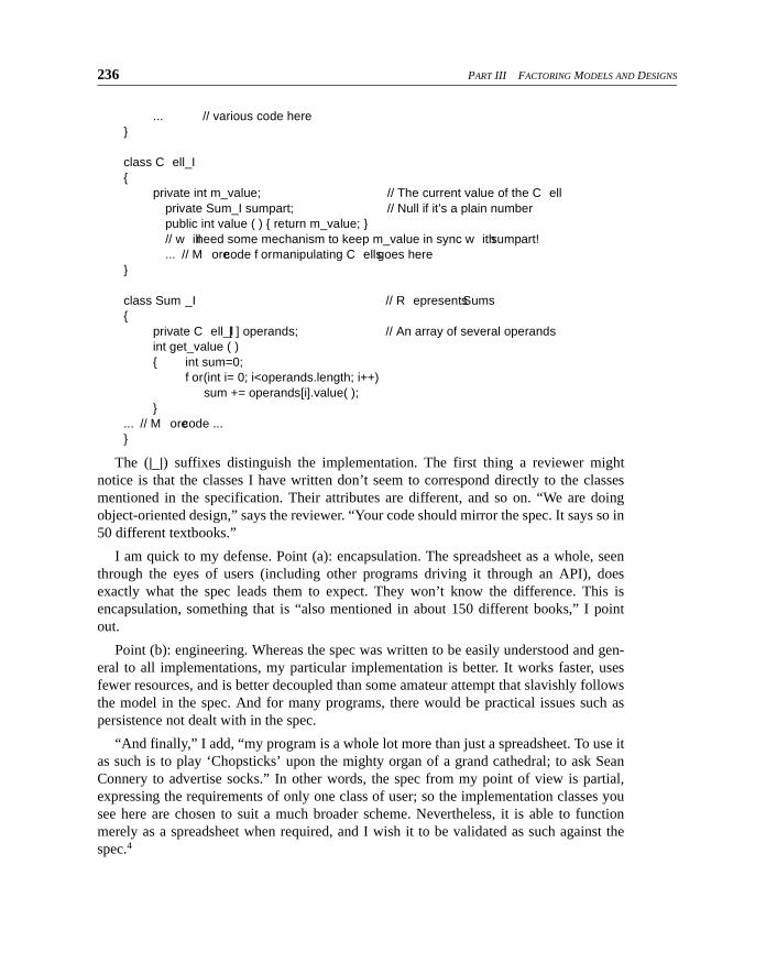
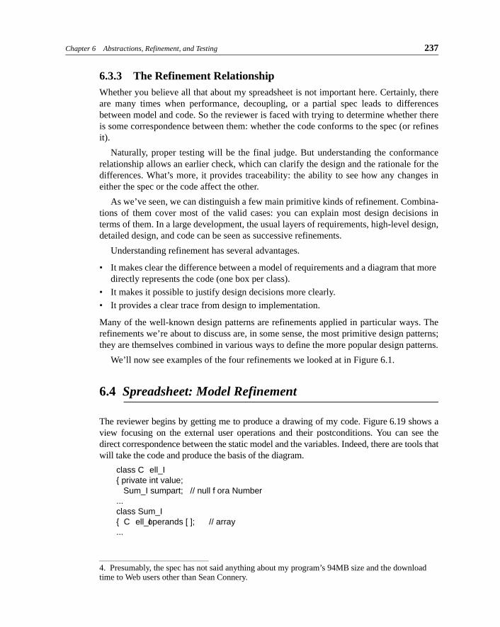
6.3.2 An ImplementationNow let’s consider an implementation. The first thing to be said is that the program code ismuch larger than the model, so we’ll see only glimpses of it. Here is some implementationcode for a spreadsheet:
package SpreadSheetImpl_1;
class SpreadSheet_I // This class implements SpreadSheet{
private C ell_I [ ] cells; // array of cells of my spreadsheet
Figure 6.18 Spreadsheet snapshots.
:Sum
value==14 23
:Number
value==4
:Number
value==3
B3 :C ell
:Sum
value==13
B4 :C ell :Sum
value==10
A2 :C ell
:Number
value==4
C 6 :C ell
:Number
value==6
A5 :C ellC 2.setSum(A2, B3)
C 2 :C ell
236 PART III FACTORING MODELS AND DESIGNS
... // various code here}
class C ell_I{
private int m_value; // The current value of the C ellprivate Sum_I sumpart; // Null if it’s a plain numberpublic int value ( ) { return m_value; }// w ill need some mechanism to keep m_value in sync w ith sumpart!... // M ore code f or manipulating C ells goes here
}
class Sum _I // R epresents Sums{
private C ell_I [ ] operands; // An array of several operandsint get_value ( ){ int sum=0;
f or (int i= 0; i<operands.length; i++)sum += operands[i].value( );
}... // M ore code ...}
The (|_|) suffixes distinguish the implementation. The first thing a reviewer mightnotice is that the classes I have written don’t seem to correspond directly to the classesmentioned in the specification. Their attributes are different, and so on. “We are doingobject-oriented design,” says the reviewer. “Your code should mirror the spec. It says so in50 different textbooks.”
I am quick to my defense. Point (a): encapsulation. The spreadsheet as a whole, seenthrough the eyes of users (including other programs driving it through an API), doesexactly what the spec leads them to expect. They won’t know the difference. This isencapsulation, something that is “also mentioned in about 150 different books,” I pointout.
Point (b): engineering. Whereas the spec was written to be easily understood and gen-eral to all implementations, my particular implementation is better. It works faster, usesfewer resources, and is better decoupled than some amateur attempt that slavishly followsthe model in the spec. And for many programs, there would be practical issues such aspersistence not dealt with in the spec.
“And finally,” I add, “my program is a whole lot more than just a spreadsheet. To use itas such is to play ‘Chopsticks’ upon the mighty organ of a grand cathedral; to ask SeanConnery to advertise socks.” In other words, the spec from my point of view is partial,expressing the requirements of only one class of user; so the implementation classes yousee here are chosen to suit a much broader scheme. Nevertheless, it is able to functionmerely as a spreadsheet when required, and I wish it to be validated as such against thespec.4
Chapter 6 Abstractions, Refinement, and Testing 237
6.3.3 The Refinement RelationshipWhether you believe all that about my spreadsheet is not important here. Certainly, thereare many times when performance, decoupling, or a partial spec leads to differencesbetween model and code. So the reviewer is faced with trying to determine whether thereis some correspondence between them: whether the code conforms to the spec (or refinesit).
Naturally, proper testing will be the final judge. But understanding the conformancerelationship allows an earlier check, which can clarify the design and the rationale for thedifferences. What’s more, it provides traceability: the ability to see how any changes ineither the spec or the code affect the other.
As we’ve seen, we can distinguish a few main primitive kinds of refinement. Combina-tions of them cover most of the valid cases: you can explain most design decisions interms of them. In a large development, the usual layers of requirements, high-level design,detailed design, and code can be seen as successive refinements.
Understanding refinement has several advantages.
• It makes clear the difference between a model of requirements and a diagram that more
directly represents the code (one box per class).
• It makes it possible to justify design decisions more clearly.
• It provides a clear trace from design to implementation.
Many of the well-known design patterns are refinements applied in particular ways. Therefinements we’re about to discuss are, in some sense, the most primitive design patterns;they are themselves combined in various ways to define the more popular design patterns.
We’ll now see examples of the four refinements we looked at in Figure 6.1.
6.4 Spreadsheet: Model Refinement
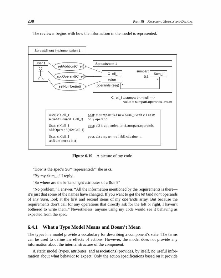
The reviewer begins by getting me to produce a drawing of my code. Figure 6.19 shows aview focusing on the external user operations and their postconditions. You can see thedirect correspondence between the static model and the variables. Indeed, there are tools thatwill take the code and produce the basis of the diagram.
class C ell_I{ private int value;
Sum_I sumpart; // null f or a Number...class Sum_I{ C ell_I operands [ ]; // array...
4. Presumably, the spec has not said anything about my program’s 94MB size and the download time to Web users other than Sean Connery.
238 PART III FACTORING MODELS AND DESIGNS
The reviewer begins with how the information in the model is represented.
“How is the spec’s Sum represented?” she asks.
“By my Sum_I,” I reply.
“So where are the lef t and right attributes of a Sum?”
“No problem,” I answer. “All the information mentioned by the requirements is there—it’s just that some of the names have changed. If you want to get the lef t and right operandsof any Sum, look at the first and second items of my operands array. But because therequirements don’t call for any operations that directly ask for the left or right, I haven’tbothered to write them.” Nevertheless, anyone using my code would see it behaving asexpected from the spec.
6.4.1 What a Type Model Means and Doesn’t MeanThe types in a model provide a vocabulary for describing a component’s state. The termscan be used to define the effects of actions. However, the model does not provide anyinformation about the internal structure of the component.
A static model (types, attributes, and associations) provides, by itself, no useful infor-mation about what behavior to expect. Only the action specifications based on it provide
Figure 6.19 A picture of my code.
Spreadsheet 1
operands {seq} *
SpreadSheet Implementation 1
Sum_IC ell_I
value
sumpart
0,1
User 1
User, ci:Cell_I post: ci.sumpart is a new Sum_I with ci1 as itssetAddition(ci1: Cell_I) only operand
setAddition(C ell)
addOperand(C ell)
setNumber(int)
C ell_I :: sumpart <> null ==> value = sumpart.operands–>sum
*
User, ci:Cell_I post: ci2 is appended to ci.sumpart.operandsaddOperand(ci2: Cell_I)
User, ci:Cell_I post: ci.sumpart=null && ci.value=nsetNumber(n : int)

Chapter 6 Abstractions, Refinement, and Testing 239
that. The complete specification is a true one if the statements it makes or implies aboutthe component’s behavior (response to actions) are always correct. Features of a statictype model not used by action specifications are redundant, having no effect on the speci-fication’s meaning.
6.4.2 Documenting Model Conformance with a RetrievalThe general rule is that, for each attribute or association in the abstract models, it shouldbe possible to write a read-only function in the implementation code that abstracts (orretrieves) its value. Here are the retrievals for Sum_I I’ve just mentioned to my reviewer:
class Sum_I{ private C ell_I [ ] operands; // array
C ell_I lef t ( ) {return operands [0]; }C ell_I right ( ) {return operands [1];}...
These abstractions happen to be particularly easy; the correspondence to the specmodel is not very far removed. Others are more complex. But it doesn’t matter if anabstraction function is hopelessly inefficient: It need only demonstrate that the informa-tion is in there somewhere. Nor does it matter if there is more information in the code thanin the model. I can store more than two operands, although readers of the official specwon’t use more than two.
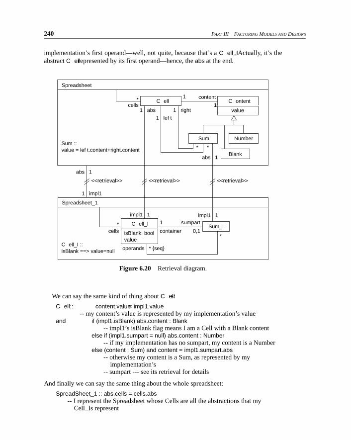
6.4.3 Drawing a Model ConformanceRetrievals can be made more clear with a diagram. It can be helpful to draw both models(or at least parts of them) on a single diagram. You can then visually relate the elementsacross the refinement using associations and write invariants that define the abstractionfunctions for all attributes in the spec.5 These associations, introduced specifically for thispurpose, are distinguished with a <<retrieval>> tag or stereotype. (We often abbreviate thatto a // marker, although in Figure 6.20 we’ve shown both.) Figure 6.20 shows that eachC ell_I in the implementation corresponds one-to-one with a C ell in the spec; the same istrue for Sum_I and Sum. All we need is to document how the attributes of C ell or Sum canbe computed from the attributes of C ell_I or Sum_I. For example:
Sum :: lef t = impl1.operands[1].absand right = impl1.operands[2].absand value = impl1.container.value
Notice what’s happening: we start with a part of the spec and go through its attributes,showing how they are realized in this implementation, which is called impl1 (not justimpl—it might have many implementations we’ve not seen yet). The lef t is given by our
5. The specification model will generally be in one package and the implementation in another. (Packages are dealt with in Chapter 7.) There may be more than one implementation, so we don’t want to put them all in one package. The conformance retrieval information may be with the imple-mentation or in its own package.
240 PART III FACTORING MODELS AND DESIGNS
implementation’s first operand—well, not quite, because that’s a C ell_I. Actually, it’s theabstract C ell represented by its first operand—hence, the abs at the end.
We can say the same kind of thing about C ells:
C ell:: content.value = impl1.value-- my content’s value is represented by my implementation’s value
and if (impl1.isBlank) abs.content : Blank-- impl1’s isBlank flag means I am a Cell with a Blank content
else if (impl1.sumpart = null) abs.content : Number-- if my implementation has no sumpart, my content is a Number
else (content : Sum) and content = impl1.sumpart.abs-- otherwise my content is a Sum, as represented by my
implementation’s-- sumpart --- see its retrieval for details
And finally we can say the same thing about the whole spreadsheet:
SpreadSheet_1 :: abs.cells = cells.abs-- I represent the Spreadsheet whose Cells are all the abstractions that my
Cell_Is represent
Figure 6.20 Retrieval diagram.
Spreadsheet_1
operands * {seq}
impl1 1
1 impl1
impl1 1
<<retrieval>> <<retrieval>> <<retrieval>>
Sum_I C ell_I
isBlank: bool value
sumpart
0,1*
cells
1
container*
Spreadsheet
Sum Number
Blank
C ontent
value
* *
1 right
1 lef t
1 abs
abs 1
abs 1
content1
1*
cells
Sum :: value = lef t.content+right.content
C ell_I :: isBlank ==> value=null
C ell
Chapter 6 Abstractions, Refinement, and Testing 241
Writing the retrieval functions doesn’t directly depend on drawing the retrieval rela-tions, but it helps where the correspondence is more or less one-to-one. Notice that wedon’t, for example, have a direct correspondence to Number.
6.4.4 Testing Using Abstraction FunctionsQA departments may insist that such retrieval (abstraction) functions should be writtendown or even written into the code. Even though these functions are not always used in thedelivered code, they are useful.
• Writing them is a good cross-check, helping to expose inconsistencies that might other-wise have been glossed over.
• They make an unambiguous statement about exactly how the abstract model has been
represented in your code.
• For testing purposes, testbeds can be written that execute the postconditions and invari-ants defined in the requirements models. These talk in terms of the abstract model’s
attributes, so the abstraction functions will be needed to get their values.
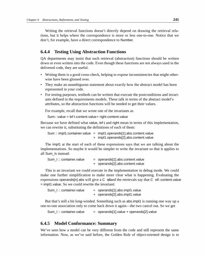
For example, recall that we wrote one of the invariants as
Sum:: value = lef t.content.value + right.content.value
Becuase we have defined what value, lef t, and right mean in terms of this implementation,we can rewrite it, substituting the definitions of each of them:
Sum :: impl1.container.value = impl1.operands[1].abs.content.value+ impl1.operands[2].abs.content.value
The impl1 at the start of each of these expressions says that we are talking about theimplementations. So maybe it would be simpler to write the invariant so that it applies toall Sum_Is instead:
Sum_I :: container.value = operands[1].abs.content.value+ operands[2].abs.content.value
This is an invariant we could execute in the implementation in debug mode. We couldmake one further simplification to make more clear what is happening. Evaluating theexpressions operands[n].abs will give a C ell; and the retrievals say that C ell::content.value= impl1.value. So we could rewrite the invariant:
Sum_I :: container.value = operands[1].abs.impl1.value+ operands[2].abs.impl1.value
But that’s still a bit long-winded. Something such as abs.impl1 is running one way up aone-to-one association only to come back down it again—the two cancel out. So we get
Sum_I :: container.value = operands[1].value + operands[2].value
6.4.5 Model Conformance: SummaryWe’ve seen how a model can be very different from the code and still represent the sameinformation. Now, as we’ve said before, the Golden Rule of object-oriented design is to
242 PART III FACTORING MODELS AND DESIGNS
choose your classes to mirror your specification model. When that is possible, the abstrac-tions are trivial, a one-to-one correspondence. But there are several circumstances when itisn’t possible, and model refinement gives us a way of understanding the relationships. Typ-ical cases include the following.
• The model that gives best execution performance is very different from one that explains clearly to clients what the object does.
• The implementation adds a lot to the specified functionality. It is possible for one
object to satisfy several specifications, especially when it plays roles in separate collab-orations (as we will see in later chapters). Each role specification will have its own
model, which must be related to the implementation.
• You specified a requirement and then bought a component that comes with its own
spec. The first thing you must work out is how its model corresponds to yours.
We’ve also said before that it is a matter of local policy how formal your documenta-tion must be. When you’re plugging components together to get an early product delivery,you don’t care about all this. But when you’re designing a component you hope will bereused many times, it is worth the extra effort. And even if you don’t go to the trouble ofwriting the abstraction functions, it is useful to do a mental check that you believe theycould be written if you were challenged to.
6.4.6 Testing by Representing the Specification in CodeWhat the Quality Assurance department really wants is to be able to represent a spec in codeso that it can be run as a test harness. They want to be able to write one set of invariants,postconditions, and so on that every candidate implementation can be tested against. As faras they are concerned, the spec writer writes a spec and associated test assertions. Eachhopeful designer must supply two things: the design plus a set of abstractions that enable thetest assertions to execute.
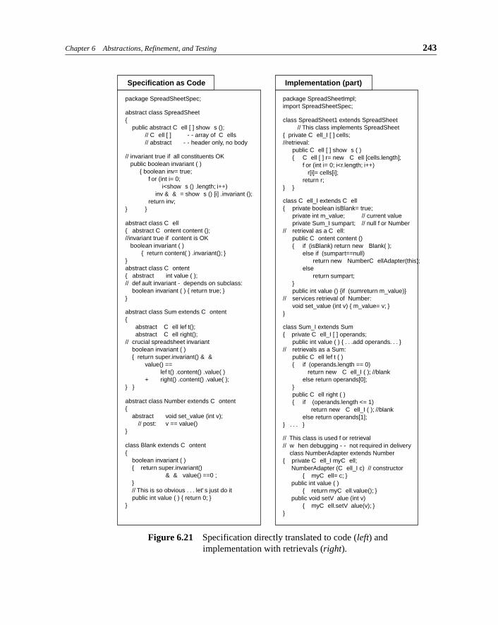
This rigorous view of specification and testing leads to a view in which all models canbe cast into program code (something that is not so tedious as it was before code-generat-ing tools). The types in a specification turn into abstract classes, of which the designer isexpected to supply implementations. Figure 6.21 on the next page shows this done for theinvariants; postconditions are omitted.
(In Java, you’d think spec types would be written as interfaces. Unfortunately, if wewant to put the invariants and postconditions into the types themselves in real executableform, they must be classes. This has the uncomfortable effect of disallowing one imple-mentation class from playing more than one role. An alternative is to put all the test appa-ratus in a separate set of classes that interrogates the states of the types. Again, we findourselves applauding Eiffel, in which all this is natural and easy.)
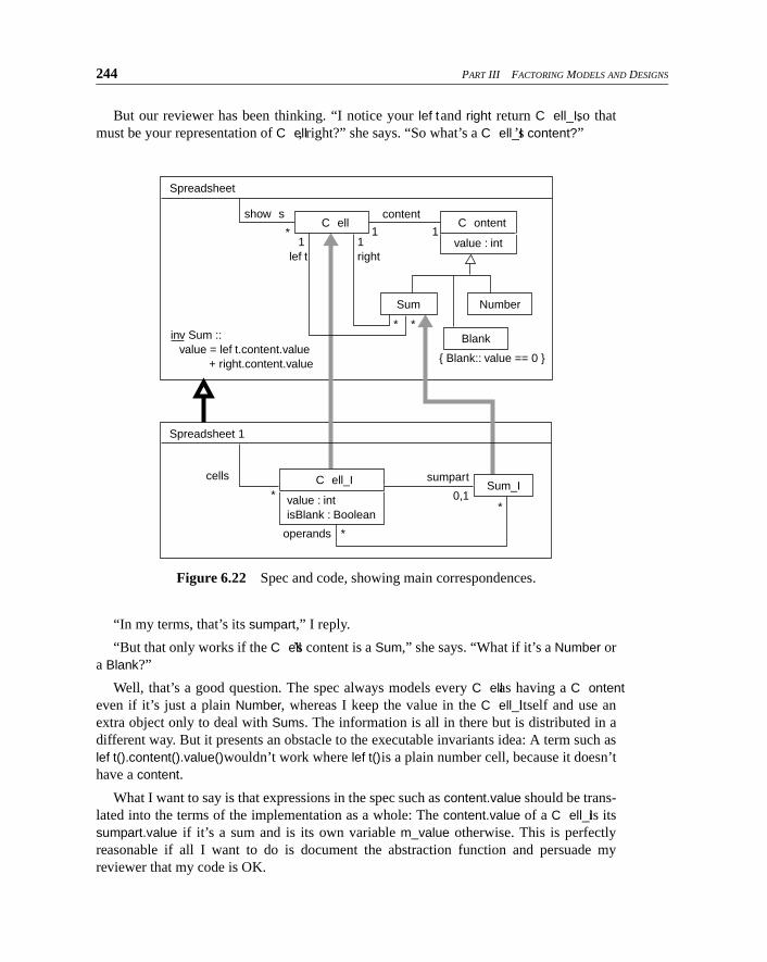
If we can write the whole thing, spec and all, in code, we can also show both theabstract model and the more detailed design in one picture—see Figure 6.22 on page 245.The C ell and Sum refinements are only model refinements, because the abstraction did notpromise any behavior requirements on those types.
Chapter 6 Abstractions, Refinement, and Testing 243
Figure 6.21 Specification directly translated to code (left) and
implementation with retrievals (right).
Specification as Code
package SpreadSheetSpec;
Implementation (part)
package SpreadSheetImpl;import SpreadSheetSpec;
class Blank extends C ontent{ boolean invariant ( ) { return super.invariant()
& & value() ==0 ; } // This is so obvious . . . let' s just do it public int value ( ) { return 0; }}
abstract class Number extends C ontent{ abstract void set_value (int v);
// post: v == value()}
abstract class Sum extends C ontent{ abstract C ell lef t(); abstract C ell right();// crucial spreadsheet invariant boolean invariant ( ) { return super.invariant() & &
value() == lef t() .content() .value( )
+ right() .content() .value( );} }
abstract class C ell{ abstract C ontent content ();//invariant true if content is OK boolean invariant ( )
{ return content( ) .invariant(); }}abstract class C ontent{ abstract int value ( );// def ault invariant - depends on subclass: boolean invariant ( ) { return true; }}
// invariant true if all constituents OK public boolean invariant ( )
{ boolean inv= true; f or (int i= 0;
i<show s () .length; i++)inv & & = show s () [i] .invariant ();
return inv;} }
abstract class SpreadSheet{ public abstract C ell [ ] show s ();
// C ell [ ] - - array of C ells// abstract - - header only, no body
// This class is used f or retrieval// w hen debugging - - not required in delivery class NumberAdapter extends Number{ private C ell_I myC ell; NumberAdapter (C ell_I c) // constructor
{ myC ell= c; } public int value ( )
{ return myC ell.value(); } public void setV alue (int v)
{ myC ell.setV alue(v); }}
class Sum_I extends Sum{ private C ell_I [ ] operands;
public int value ( ) { . . .add operands. . . }// retrievals as a Sum:
public C ell lef t ( ){ if (operands.length == 0)
return new C ell_I ( ); //blankelse return operands[0];
}public C ell right ( ){ if (operands.length <= 1)
return new C ell_I ( ); //blankelse return operands[1];
} . . . }
class C ell_I extends C ell{ private boolean isBlank= true;
private int m_value; // current valueprivate Sum_I sumpart; // null f or Number
// retrieval as a C ell:public C ontent content (){ if (isBlank) return new Blank( );
else if (sumpart==null)return new NumberC ellAdapter(this);
elsereturn sumpart;
}public int value () {if (sumreturn m_value)}
// services retrieval of Number:void set_value (int v) { m_value= v; }
}
class SpreadSheet1 extends SpreadSheet // This class implements SpreadSheet
{ private C ell_I [ ] cells;//retrieval:
public C ell [ ] show s ( ){ C ell [ ] r= new C ell [cells.length];
f or (int i= 0; i<r.length; i++) r[i]= cells[i];return r;
} }
244 PART III FACTORING MODELS AND DESIGNS
But our reviewer has been thinking. “I notice your lef t and right return C ell_I, so thatmust be your representation of C ell, right?” she says. “So what’s a C ell_I’s content?”
“In my terms, that’s its sumpart,” I reply.
“But that only works if the C ell’s content is a Sum,” she says. “What if it’s a Number ora Blank?”
Well, that’s a good question. The spec always models every C ell as having a C ontenteven if it’s just a plain Number, whereas I keep the value in the C ell_I itself and use anextra object only to deal with Sums. The information is all in there but is distributed in adifferent way. But it presents an obstacle to the executable invariants idea: A term such aslef t().content().value() wouldn’t work where lef t() is a plain number cell, because it doesn’thave a content.
What I want to say is that expressions in the spec such as content.value should be trans-lated into the terms of the implementation as a whole: The content.value of a C ell_I is itssumpart.value if it’s a sum and is its own variable m_value otherwise. This is perfectlyreasonable if all I want to do is document the abstraction function and persuade myreviewer that my code is OK.
Figure 6.22 Spec and code, showing main correspondences.
Spreadsheet
C ell
Sum Number
Blank
{ Blank:: value == 0 }
show sC ontent
value : int
*
*
*
1
lef t1
right
content
1 1
inv Sum :: value = lef t.content.value + right.content.value
Spreadsheet 1
operands *
Sum_I C ell_I
value : int isBlank : Boolean
sumpart
0,1**
cells
Chapter 6 Abstractions, Refinement, and Testing 245
But for executable test assertions, content() must return something that will then returnthe appropriate value(). This leads to the invention of the class NumberAdapter (so now wehave abstraction classes as well as functions). It can be kept fairly minimal. All it must dois know our implementation well enough to extract any information required by the testassertions in the spec type Number.
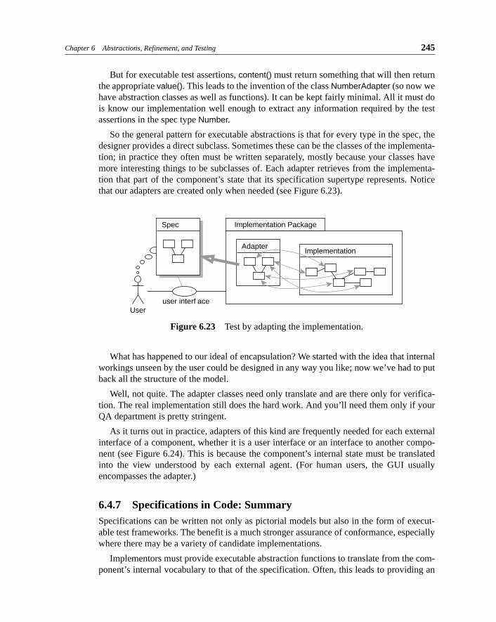
So the general pattern for executable abstractions is that for every type in the spec, thedesigner provides a direct subclass. Sometimes these can be the classes of the implementa-tion; in practice they often must be written separately, mostly because your classes havemore interesting things to be subclasses of. Each adapter retrieves from the implementa-tion that part of the component’s state that its specification supertype represents. Noticethat our adapters are created only when needed (see Figure 6.23).
What has happened to our ideal of encapsulation? We started with the idea that internalworkings unseen by the user could be designed in any way you like; now we’ve had to putback all the structure of the model.
Well, not quite. The adapter classes need only translate and are there only for verifica-tion. The real implementation still does the hard work. And you’ll need them only if yourQA department is pretty stringent.
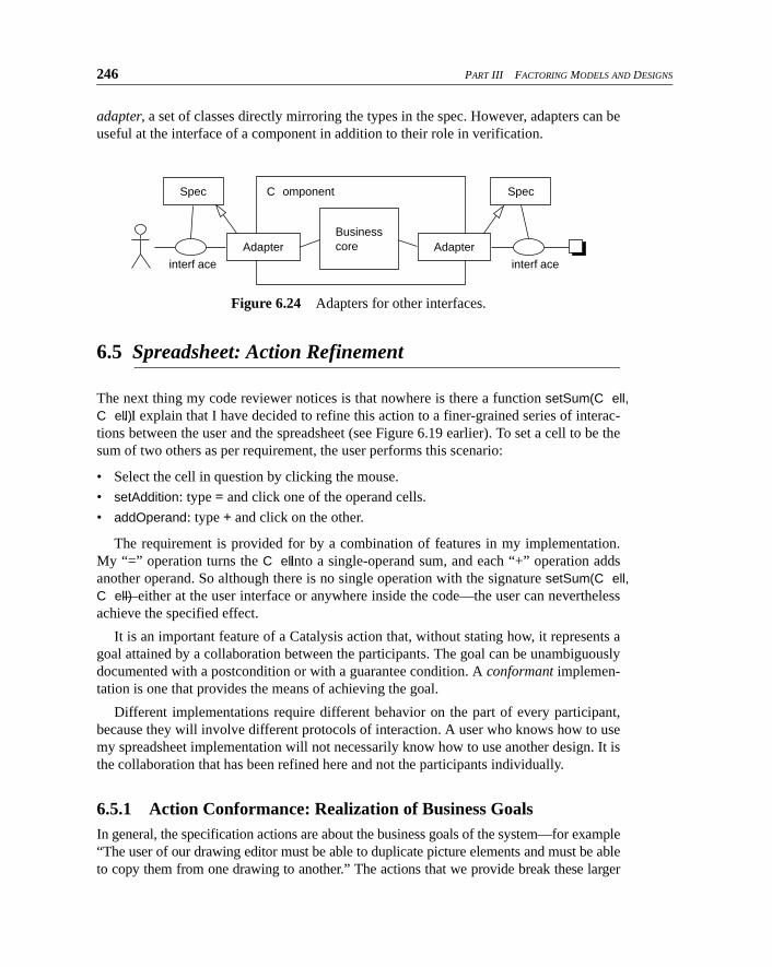
As it turns out in practice, adapters of this kind are frequently needed for each externalinterface of a component, whether it is a user interface or an interface to another compo-nent (see Figure 6.24). This is because the component’s internal state must be translatedinto the view understood by each external agent. (For human users, the GUI usuallyencompasses the adapter.)
6.4.7 Specifications in Code: SummarySpecifications can be written not only as pictorial models but also in the form of execut-able test frameworks. The benefit is a much stronger assurance of conformance, especiallywhere there may be a variety of candidate implementations.
Implementors must provide executable abstraction functions to translate from the com-ponent’s internal vocabulary to that of the specification. Often, this leads to providing an
Figure 6.23 Test by adapting the implementation.
Spec Implementation Package
Useruser interf ace
AdapterImplementation
246 PART III FACTORING MODELS AND DESIGNS
adapter, a set of classes directly mirroring the types in the spec. However, adapters can beuseful at the interface of a component in addition to their role in verification.
6.5 Spreadsheet: Action Refinement
The next thing my code reviewer notices is that nowhere is there a function setSum(C ell,C ell). I explain that I have decided to refine this action to a finer-grained series of interac-tions between the user and the spreadsheet (see Figure 6.19 earlier). To set a cell to be thesum of two others as per requirement, the user performs this scenario:
• Select the cell in question by clicking the mouse.
• setAddition: type = and click one of the operand cells.
• addOperand: type + and click on the other.
The requirement is provided for by a combination of features in my implementation.My “=” operation turns the C ell into a single-operand sum, and each “+” operation addsanother operand. So although there is no single operation with the signature setSum(C ell,C ell)—either at the user interface or anywhere inside the code—the user can neverthelessachieve the specified effect.
It is an important feature of a Catalysis action that, without stating how, it represents agoal attained by a collaboration between the participants. The goal can be unambiguouslydocumented with a postcondition or with a guarantee condition. A conformant implemen-tation is one that provides the means of achieving the goal.
Different implementations require different behavior on the part of every participant,because they will involve different protocols of interaction. A user who knows how to usemy spreadsheet implementation will not necessarily know how to use another design. It isthe collaboration that has been refined here and not the participants individually.
6.5.1 Action Conformance: Realization of Business GoalsIn general, the specification actions are about the business goals of the system—for example“The user of our drawing editor must be able to duplicate picture elements and must be ableto copy them from one drawing to another.” The actions that we provide break these larger
Figure 6.24 Adapters for other interfaces.
Spec
interf ace interf ace
C omponent Spec
Adapter AdapterBusiness
core
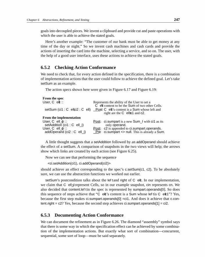
Chapter 6 Abstractions, Refinement, and Testing 247
goals into decoupled pieces. We invent a clipboard and provide cut and paste operations withwhich the user is able to achieve the stated goals.
Here’s another example: “The customer of our bank must be able to get money at anytime of the day or night.” So we invent cash machines and cash cards and provide theactions of inserting the card into the machine, selecting a service, and so on. The user, withthe help of a good user interface, uses these actions to achieve the stated goals.
6.5.2 Checking Action ConformanceWe need to check that, for every action defined in the specification, there is a combinationof implementation actions that the user could follow to achieve the defined goal. Let’s takesetSum as an example.
The action specs shown here were given in Figure 6.17 and Figure 6.19:
From the specUser, C ell c :: Represents the ability of the User to set a
C ell’s content to be the Sum of two other Cells.setSum (ci1 : C ell, ci2 : C ell) Post: C ell c’s content is a Sum whose left and
right are the C ells c1 and c2.From the implementationUser, C ell_| ci :: Post: ci.sumpart is a new Sum_I with ci1 as its
setAddition (ci1 : C ell_|) only operand.User, C ell_| ci :: Post: c2 is appended to ci.sumpart.operands.
addOperand (ci2 : C ell_|) Pre: ci.sumpart <> null. This is already a Sum.
A little thought suggests that a setAddition followed by an addOperand should achievethe effect of a setSum. A comparison of snapshots in the two views will help; the arrowsshow which links are created by each action (see Figure 6.25).
Now we can see that performing the sequence
<ci.setAddition(ci1), ci.addOperand(ci2)>
should achieve an effect corresponding to the spec’s c.setSum(c1, c2). To be absolutelysure, we can use the abstraction functions we worked out earlier.
setSum’s postcondition talks about the lef t and right of C ell c. In our implementation,we claim that C ell_Is represent Cells, so in our example snapshot, cin represents cn. Wealso decided that content.lef t in the spec is represented by sumpart.operands[0]. So doesthis sequence of steps achieve that “C ell c’s content is a Sum whose lef t is C ell c1”? Yes,because the first step makes ci.sumpart.operands[0] =ci1. And does it achieve that c.con-tent.right = c2? Yes, because the second step achieves ci.sumpart.operands[1] = ci2.
6.5.3 Documenting Action ConformanceWe can document the refinement as in Figure 6.26. The diamond “assembly” symbol saysthat there is some way in which the specification effect can be achieved by some combina-tion of the implementation actions. But exactly what sort of combination—concurrent,sequential, some sort of loop—must be said separately.
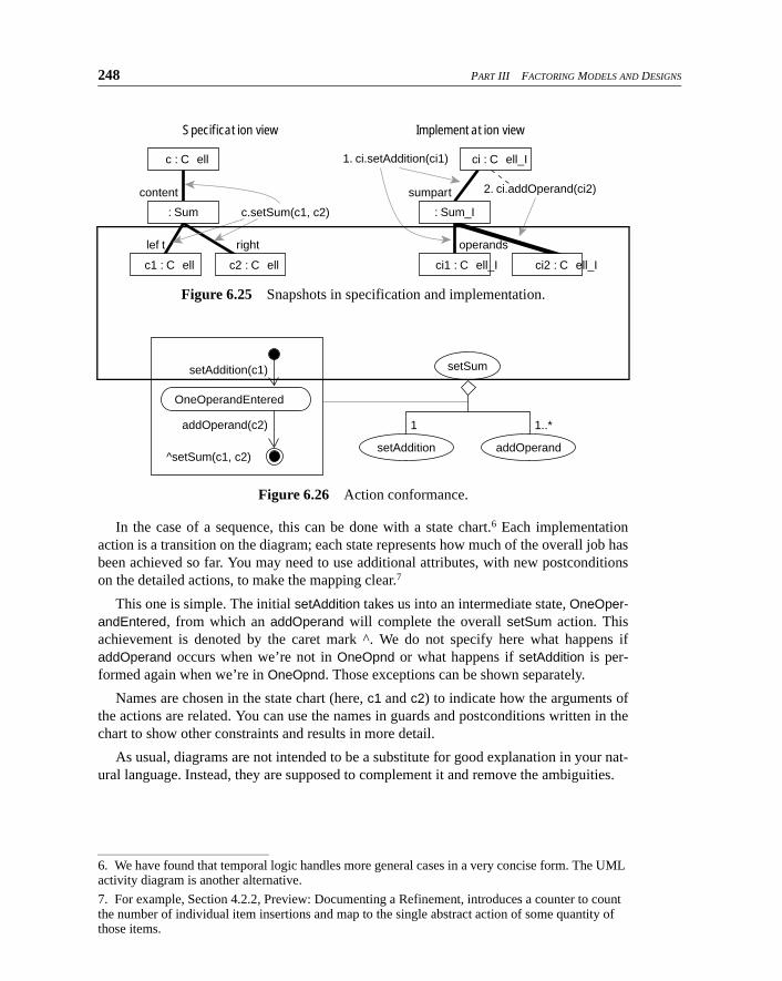
248 PART III FACTORING MODELS AND DESIGNS
In the case of a sequence, this can be done with a state chart.6 Each implementationaction is a transition on the diagram; each state represents how much of the overall job hasbeen achieved so far. You may need to use additional attributes, with new postconditionson the detailed actions, to make the mapping clear.7
This one is simple. The initial setAddition takes us into an intermediate state, OneOper-andEntered, from which an addOperand will complete the overall setSum action. Thisachievement is denoted by the caret mark ^. We do not specify here what happens ifaddOperand occurs when we’re not in OneOpnd or what happens if setAddition is per-formed again when we’re in OneOpnd. Those exceptions can be shown separately.
Names are chosen in the state chart (here, c1 and c2) to indicate how the arguments ofthe actions are related. You can use the names in guards and postconditions written in thechart to show other constraints and results in more detail.
As usual, diagrams are not intended to be a substitute for good explanation in your nat-ural language. Instead, they are supposed to complement it and remove the ambiguities.
Figure 6.25 Snapshots in specification and implementation.
Figure 6.26 Action conformance.
6. We have found that temporal logic handles more general cases in a very concise form. The UML activity diagram is another alternative.
7. For example, Section 4.2.2, Preview: Documenting a Refinement, introduces a counter to count the number of individual item insertions and map to the single abstract action of some quantity of those items.
Specification view
c.setSum(c1, c2)
lef t right
content
Implementation view
2. ci.addOperand(ci2)
1. ci.setAddition(ci1)
operands
sumpart
c2 : C ellc1 : C ell ci1 : C ell_I ci2 : C ell_I
ci : C ell_I
: Sum_I
c : C ell
: Sum
OneOperandEntered
setAddition(c1)
addOperand(c2)
^setSum(c1, c2)setAddition
setSum
addOperand
1 1..*
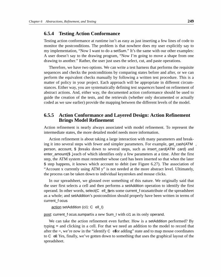
Chapter 6 Abstractions, Refinement, and Testing 249
6.5.4 Testing Action ConformanceTesting action conformance at runtime isn’t as easy as just inserting a few lines of code tomonitor the postconditions. The problem is that nowhere does my user explicitly say tomy implementation, “Now I want to do a setSum.” It’s the same with our other examples:A user doesn’t say to the drawing program, “Now I’m going to move a shape from onedrawing to another.” Rather, the user just uses the select, cut, and paste operations.
Therefore, we have two options. We can write a test harness that performs the requisitesequences and checks the postconditions by comparing states before and after, or we canperform the equivalent checks manually by following a written test procedure. This is amatter of policy in your project. Each approach will be appropriate in different circum-stances. Either way, you are systematically defining test sequences based on refinement ofabstract actions. And, either way, the documented action conformance should be used toguide the creation of the tests, and the retrievals (whether only documented or actuallycoded as we saw earlier) provide the mapping between the different levels of the model.
6.5.5 Action Conformance and Layered Design: Action Refinement Brings Model Refinement
Action refinement is nearly always associated with model refinement. To represent theintermediate states, the more detailed model needs more information.
Action refinement is about taking a large interaction with many parameters and break-ing it into several steps with fewer and simpler parameters. For example, get_cash(ATM ,person, account, $ ) breaks down to several steps, such as insert_card(ATM , card) andenter_amount($ ), each of which identifies only a few parameters at a time. After the firststep, the ATM system must remember whose card has been inserted so that when the later$ step happens, it knows which account to debit (see Figure 6.27). The association of“Account x currently using ATM y” is not needed at the more abstract level. Ultimately,the process can be taken down to individual keystrokes and mouse clicks.
In our spreadsheet, we glossed over something of this nature. We originally said thatthe user first selects a cell and then performs a setAddition operation to identify the firstoperand. In other words, select(C ell_I) sets some current_f ocus attribute of the spreadsheetas a whole; and setAddition’s postcondition should properly have been written in terms ofcurrent_f ocus.
action setAddition (ci1: C ell_I)
post: current_f ocus.sumpart is a new Sum_I with ci1 as its only operand.
We can take the action refinement even further. How is a setAddition performed? Bytyping = and clicking in a cell. For that we need an addition to the model to record thatafter the =, we’re now in the “identify C ell for adding” state and to map mouse coordinatesto C ells. Yes, finally, we’ve gotten down to something that uses the graphical layout of thespreadsheet.
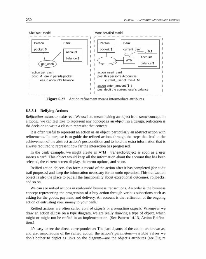
250 PART III FACTORING MODELS AND DESIGNS
6.5.5.1 Reifying Actions
Reification means to make real. We use it to mean making an object from some concept. Ina model, we can feel free to represent any concept as an object; in a design, reification isthe decision to write a class to represent that concept.
It is often useful to represent an action as an object, particularly an abstract action withrefinements. Its purpose is to guide the refined actions through the steps that lead to theachievement of the abstract action’s postcondition and to hold the extra information that isalways required to represent how far the interaction has progressed.
In the bank example, we might create an ATM _transaction object as soon as a userinserts a card. This object would keep all the information about the account that has beenselected, the current screen display, the menu options, and so on.
Reified action objects also form a record of the action after it has completed (for audittrail purposes) and keep the information necessary for an undo operation. This transactionobject is also the place to put all the functionality about exceptional outcomes, rollbacks,and so on.
We can see reified actions in real-world business transactions. An order is the businessconcept representing the progression of a buy action through various subactions such asasking for the goods, payment, and delivery. An account is the reification of the ongoingaction of entrusting your money to your bank.
Reified actions are often called control objects or transaction objects. Whenever wedraw an action ellipse on a type diagram, we are really drawing a type of object, whichmight or might not be reified in an implementation. (See Pattern 14.13, Action Reifica-tion.)
It’s easy to see the direct correspondence: The participants of the action are drawn as,and are, associations of the reified action; the action’s parameters—variable values wedon’t bother to depict as links on the diagram—are the object’s attributes (see Figure
Figure 6.27 Action refinement means intermediate attributes.
Abstract model
Person
pocket: $
Bank
Account
balance:$
get_cash
action get_cash
post:M ore in person’s pocket, less in account’s balance
More detailed model
Person
pocket: $
Bank
current_user
Account
balance:$ATM
action insert_card
post this person’s Account is
current_user of this ATM
action enter_amount ($ ) post debit the current_user’s balance
0,10,1
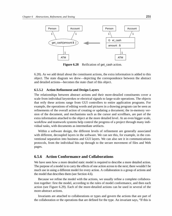
Chapter 6 Abstractions, Refinement, and Testing 251
6.28). As we add detail about the constituent actions, the extra information is added to thisobject. The state diagram we drew—depicting the correspondence between the abstractand detailed actions—becomes the state chart of this object.
6.5.5.2 Action Refinement and Design Layers
The relationships between abstract actions and their more-detailed constituents cover ascale from individual keystrokes or electrical signals to large-scale operations. The objectsthat reify these actions range from GUI controllers to entire application programs. Forexample, the operations of editing words and pictures in a drawing program can be seen asrefinements of the overall action of creating or updating a document; the in-memory ver-sion of the document, and mechanisms such as the cursor and scrollbars, are part of theextra information attached to the object at the more detailed level. At an even bigger scale,workflow and teamwork systems help control the progress of a project through many indi-vidual tasks, with documents as intermediate artifacts.
Within a software design, the different levels of refinement are generally associatedwith different, decoupled layers in the software. We can see this, for example, in the con-ventional separation into business and GUI layers. We can also see it in communicationsprotocols, from the individual bits up through to the secure movement of files and Webpages.
6.5.6 Action Conformance and CollaborationsWe have seen how a more detailed static model is required to describe a more detailed action.The purpose of a model is to carry the effects of one action across to the next; there wouldn’t bemuch use in using a different model for every action. A collaboration is a group of actions andthe model that describes them (see Section 4.6).
Because we refine the model with the actions, we usually refine a complete collabora-tion together: first the model, according to the rules of model conformance, and then eachaction (see Figure 6.29). Each of the more-detailed actions can be used in several of themore-abstract actions.
Invariants are attached to collaborations or types and govern the actions that are part ofthe collaboration or the operations that are defined for the type. An invariant says, “If this is
Figure 6.28 Reification of get_cash action.
Person Account
ATM
get_cash(amount:$ )
1 1
1
Person Account
ATM
1 1
1
G et_cash
amount : $
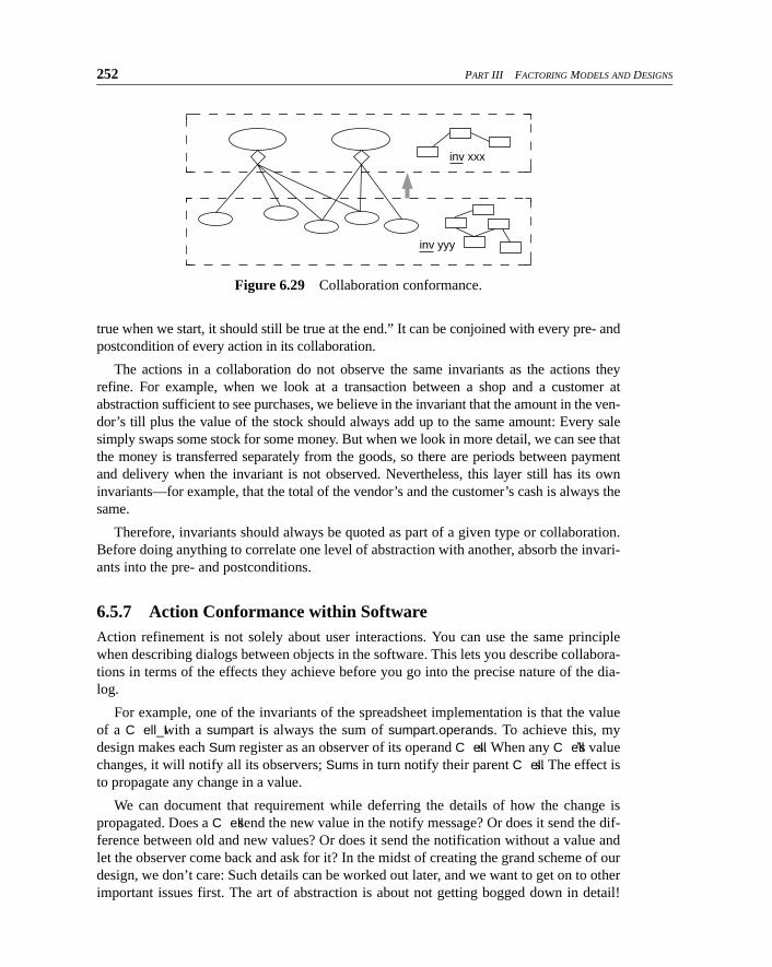
252 PART III FACTORING MODELS AND DESIGNS
true when we start, it should still be true at the end.” It can be conjoined with every pre- andpostcondition of every action in its collaboration.
The actions in a collaboration do not observe the same invariants as the actions theyrefine. For example, when we look at a transaction between a shop and a customer atabstraction sufficient to see purchases, we believe in the invariant that the amount in the ven-dor’s till plus the value of the stock should always add up to the same amount: Every salesimply swaps some stock for some money. But when we look in more detail, we can see thatthe money is transferred separately from the goods, so there are periods between paymentand delivery when the invariant is not observed. Nevertheless, this layer still has its owninvariants—for example, that the total of the vendor’s and the customer’s cash is always thesame.
Therefore, invariants should always be quoted as part of a given type or collaboration.Before doing anything to correlate one level of abstraction with another, absorb the invari-ants into the pre- and postconditions.
6.5.7 Action Conformance within SoftwareAction refinement is not solely about user interactions. You can use the same principlewhen describing dialogs between objects in the software. This lets you describe collabora-tions in terms of the effects they achieve before you go into the precise nature of the dia-log.
For example, one of the invariants of the spreadsheet implementation is that the valueof a C ell_I with a sumpart is always the sum of sumpart.operands. To achieve this, mydesign makes each Sum register as an observer of its operand C ells. When any C ell’s valuechanges, it will notify all its observers; Sums in turn notify their parent C ells. The effect isto propagate any change in a value.
We can document that requirement while deferring the details of how the change ispropagated. Does a C ell send the new value in the notify message? Or does it send the dif-ference between old and new values? Or does it send the notification without a value andlet the observer come back and ask for it? In the midst of creating the grand scheme of ourdesign, we don’t care: Such details can be worked out later, and we want to get on to otherimportant issues first. The art of abstraction is about not getting bogged down in detail!
Figure 6.29 Collaboration conformance.
inv xxx
inv yyy
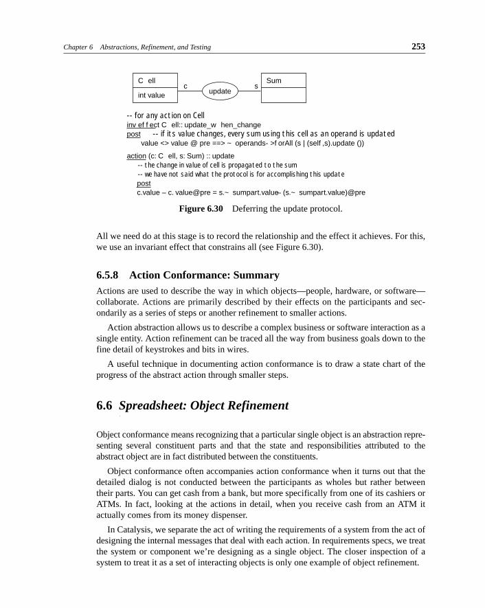
Chapter 6 Abstractions, Refinement, and Testing 253
All we need do at this stage is to record the relationship and the effect it achieves. For this,we use an invariant effect that constrains all (see Figure 6.30).
6.5.8 Action Conformance: SummaryActions are used to describe the way in which objects—people, hardware, or software—collaborate. Actions are primarily described by their effects on the participants and sec-ondarily as a series of steps or another refinement to smaller actions.
Action abstraction allows us to describe a complex business or software interaction as asingle entity. Action refinement can be traced all the way from business goals down to thefine detail of keystrokes and bits in wires.
A useful technique in documenting action conformance is to draw a state chart of theprogress of the abstract action through smaller steps.
6.6 Spreadsheet: Object Refinement
Object conformance means recognizing that a particular single object is an abstraction repre-senting several constituent parts and that the state and responsibilities attributed to theabstract object are in fact distributed between the constituents.
Object conformance often accompanies action conformance when it turns out that thedetailed dialog is not conducted between the participants as wholes but rather betweentheir parts. You can get cash from a bank, but more specifically from one of its cashiers orATMs. In fact, looking at the actions in detail, when you receive cash from an ATM itactually comes from its money dispenser.
In Catalysis, we separate the act of writing the requirements of a system from the act ofdesigning the internal messages that deal with each action. In requirements specs, we treatthe system or component we’re designing as a single object. The closer inspection of asystem to treat it as a set of interacting objects is only one example of object refinement.
Figure 6.30 Deferring the update protocol.
C ell
int value
Sumc s
-- for any action on Cellinv ef f ect C ell:: update_w hen_changepost -- if its value changes, every sum using this cell as an operand is updated value <> value @ pre ==> ~ operands- >f orAll (s | (self ,s).update ())
action (c: C ell, s: Sum) :: update -- the change in value of cell is propagated to the sum -- we have not said what the protocol is for accomplishing this update post c.value – c. value@pre = s.~ sumpart.value – (s.~ sumpart.value)@pre
update
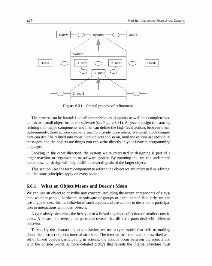
254 PART III FACTORING MODELS AND DESIGNS
The process can be fractal: Like all our techniques, it applies as well to a complete sys-tem as to a small object inside the software (see Figure 6.31). A system design can start byrefining into major components and then can define the high-level actions between them.Subsequently, those actions can be refined to provide more interactive detail. Each compo-nent can itself be refined into constituent objects and so on, until the actions are individualmessages, and the objects are things you can write directly in your favorite programminglanguage.
Looking in the other direction, the system we’re interested in designing is part of alarger machine or organization or software system. By zooming out, we can understandbetter how our design will help fulfill the overall goals of the larger object.
This section uses the term component to refer to the object we are interested in refining,but the same principles apply on every scale.
6.6.1 What an Object Means and Doesn’t MeanWe can use an object to describe any concept, including the active components of a sys-tem, whether people, hardware, or software or groups or parts thereof. Similarly, we canuse a type to describe the behavior of such objects and use actions to describe its participa-tion in interactions with other objects.
A type always describes the behavior of a linked-together collection of smaller constit-uents. A closer look reveals the parts and reveals that different parts deal with differentbehavior.
To specify the abstract object’s behavior, we use a type model that tells us nothingabout the abstract object’s internal structure. The internal structure can be described as aset of linked objects participating in actions; the actions occur between the objects andwith the outside world. A more detailed picture that reveals the internal structure must
Figure 6.31 Fractal process of refinement.
C mpt1UserA UserB
C mpt3
C mpt2
UserA UserBSystem
System
C mpt3
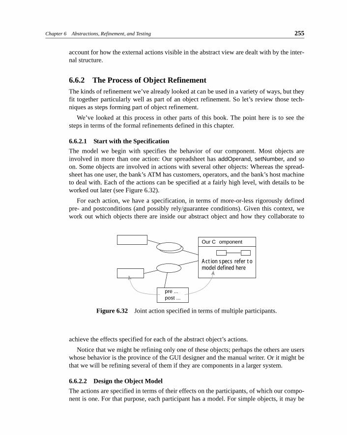
Chapter 6 Abstractions, Refinement, and Testing 255
account for how the external actions visible in the abstract view are dealt with by the inter-nal structure.
6.6.2 The Process of Object RefinementThe kinds of refinement we’ve already looked at can be used in a variety of ways, but theyfit together particularly well as part of an object refinement. So let’s review those tech-niques as steps forming part of object refinement.
We’ve looked at this process in other parts of this book. The point here is to see thesteps in terms of the formal refinements defined in this chapter.
6.6.2.1 Start with the Specification
The model we begin with specifies the behavior of our component. Most objects areinvolved in more than one action: Our spreadsheet has addOperand, setNumber, and soon. Some objects are involved in actions with several other objects: Whereas the spread-sheet has one user, the bank’s ATM has customers, operators, and the bank’s host machineto deal with. Each of the actions can be specified at a fairly high level, with details to beworked out later (see Figure 6.32).
For each action, we have a specification, in terms of more-or-less rigorously definedpre- and postconditions (and possibly rely/guarantee conditions). Given this context, wework out which objects there are inside our abstract object and how they collaborate to
achieve the effects specified for each of the abstract object’s actions.
Notice that we might be refining only one of these objects; perhaps the others are userswhose behavior is the province of the GUI designer and the manual writer. Or it might bethat we will be refining several of them if they are components in a larger system.
6.6.2.2 Design the Object Model
The actions are specified in terms of their effects on the participants, of which our compo-nent is one. For that purpose, each participant has a model. For simple objects, it may be
Figure 6.32 Joint action specified in terms of multiple participants.
Action specs refer tomodel defined here
Our C omponent
pre ... post ...
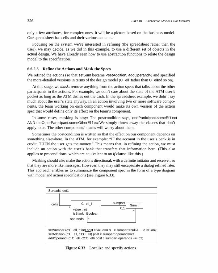
256 PART III FACTORING MODELS AND DESIGNS
only a few attributes; for complex ones, it will be a picture based on the business model.Our spreadsheet has cells and their various contents.
Focusing on the system we’re interested in refining (the spreadsheet rather than theuser), we may decide, as we did in this example, to use a different set of objects in theactual design. We have already seen how to use abstraction functions to relate the designmodel to the specification.
6.6.2.3 Refine the Actions and Mask the Specs
We refined the actions (so that setSum became <setAddition, addOperand>) and specifiedthe more-detailed versions in terms of the design model (C ell_I rather than C ell and so on).
At this stage, we mask: remove anything from the action specs that talks about the otherparticipants in the actions. For example, we don’t care about the state of the ATM user’spocket as long as the ATM dishes out the cash. In the spreadsheet example, we didn’t saymuch about the user’s state anyway. In an action involving two or more software compo-nents, the team working on each component would make its own version of the actionspec that would define only its effect on the team’s component.
In some cases, masking is easy: The postcondition says, oneParticipant.someEf f ectAND theOtherParticipant.someOtherEf f ect. We simply throw away the clauses that don’tapply to us. The other components’ teams will worry about them.
Sometimes the postcondition is written so that the effect on our component depends onsomething elsewhere. In the ATM, for example: “IF the account in the user’s bank is incredit, THEN the user gets the money.” This means that, in refining the action, we mustinclude an action with the user’s bank that transfers that information here. (This alsoapplies to preconditions, which are equivalent to an if clause like this.)
Masking should also make the actions directional, with a definite initiator and receiver, sothat they are more like messages. However, they may still encapsulate a dialog refined later.This approach enables us to summarize the component spec in the form of a type diagramwith model and action specifications (see Figure 6.33).
Figure 6.33 Localize and specify actions.
Spreadsheet1
setNumber (c:C ell, n:int) post c.value=n & c.sumpart=null & ! c.isBlank
setAddition (c:C ell, c1:C ell) post c.sumpart.operands=c1
addOperand (c: C ell, c2:C ell) post c.sumpart.operands += {c2}
operands *
Sum_I C ell_I
value : int isBlank : Boolean
sumpart
0,1**
cells
Chapter 6 Abstractions, Refinement, and Testing 257
We refine the actions down from the highest-level business abstractions but not downto individual keystrokes or electrical pulses. We refine actions to the point where theymake sense as individual actions on the objects we have chosen for our design—if youlike, to the same conceptual layer as our design. “Make a spreadsheet” is too abstract forour design; “click mouse at (x,y)” is too detailed; but setNumber(n) makes sense as a mes-sage to one of our cells.
All such judgments are relative. Working in the GUI layer, mouse clicks and keystrokesare what we deal with, and the job is to parse them into actions that can be dealt with bythe spreadsheet core. Working in a workflow system, the creation of a spreadsheet mightbe only one action, so that, from its point of view, the spreadsheet program is all a detail ofthe user interface that builds a series of cell-setting operations into one spreadsheet cre-ation. A good guideline is this: “What would constitute a useful unit of work for the cli-ent?”—something the client would cheerfully pay for.
6.6.2.4 Localize Each Action to a Constituent Object
We now make each action the prime responsibility of one of the design objects internal toour component. Usually, a good choice is the proxy object that represents the external par-ticipant of the action, which might be a user, a piece of hardware, or a software object in adifferent component. If there is no such proxy—as in our spreadsheet, which has no repre-sentation of its user—then one of the action’s parameters is the next choice. We’ll choosethe target C ell c. (In any case, a proxy often just sends the message to one of the parame-ters. But there is good pattern in which all messages to and from an external object shouldgo through their local proxy, which thereby keeps abreast of what its external counterpartis up to.)
With the assignment of a component action to one of its constituents must, of course,go the specification of what it is supposed to achieve.
6.6.2.5 Operation Refinement for Each Component-Level Action
Now we work out how each component-level action is dealt with by the object it is assignedto—in other words, we design the sequence or write the operation code so as to meet thespec. Typically, this means sending messages to other objects.
We could put it more generally and say that each object can initiate actions with one ormore other objects. You may know what you need to achieve and who should be involved,but you may not care (yet) how it is to be achieved or who should be primarily responsiblefor each part.
The receiving objects must themselves be designed, so they then pass messages toother objects. The result is that many of the component’s internal objects now have theirown specified actions.
We repeat the procedure for each of the component-level actions. The component’sresponsibilities are now distributed among its constituents. This is the essence of objectrefinement.
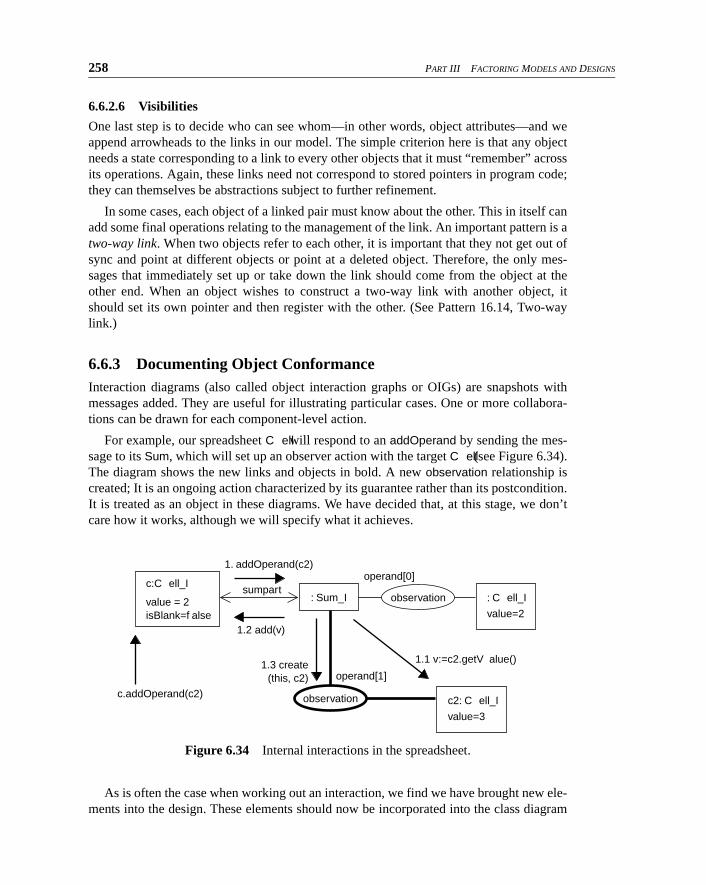
258 PART III FACTORING MODELS AND DESIGNS
6.6.2.6 Visibilities
One last step is to decide who can see whom—in other words, object attributes—and weappend arrowheads to the links in our model. The simple criterion here is that any objectneeds a state corresponding to a link to every other objects that it must “remember” acrossits operations. Again, these links need not correspond to stored pointers in program code;they can themselves be abstractions subject to further refinement.
In some cases, each object of a linked pair must know about the other. This in itself canadd some final operations relating to the management of the link. An important pattern is atwo-way link. When two objects refer to each other, it is important that they not get out ofsync and point at different objects or point at a deleted object. Therefore, the only mes-sages that immediately set up or take down the link should come from the object at theother end. When an object wishes to construct a two-way link with another object, itshould set its own pointer and then register with the other. (See Pattern 16.14, Two-waylink.)
6.6.3 Documenting Object ConformanceInteraction diagrams (also called object interaction graphs or OIGs) are snapshots withmessages added. They are useful for illustrating particular cases. One or more collabora-tions can be drawn for each component-level action.
For example, our spreadsheet C ell will respond to an addOperand by sending the mes-sage to its Sum, which will set up an observer action with the target C ell (see Figure 6.34).The diagram shows the new links and objects in bold. A new observation relationship iscreated; It is an ongoing action characterized by its guarantee rather than its postcondition.It is treated as an object in these diagrams. We have decided that, at this stage, we don’tcare how it works, although we will specify what it achieves.
As is often the case when working out an interaction, we find we have brought new ele-ments into the design. These elements should now be incorporated into the class diagram
Figure 6.34 Internal interactions in the spreadsheet.
c:C ell_I
value = 2
isBlank=f alse
: Sum_I : C ell_I value=2
c2: C ell_I value=3
observation
observation
c.addOperand(c2)
1.2 add(v)
1. addOperand(c2)operand[0]
operand[1]1.3 create
(this, c2)
1.1 v:=c2.getV alue()
sumpart
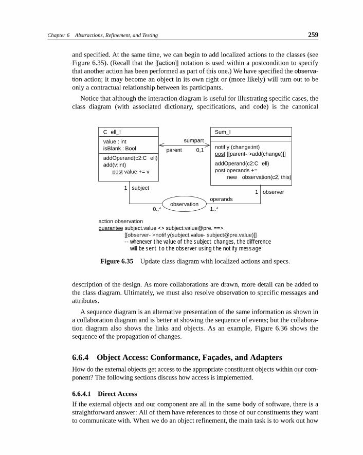
Chapter 6 Abstractions, Refinement, and Testing 259
and specified. At the same time, we can begin to add localized actions to the classes (seeFigure 6.35). (Recall that the [[action]] notation is used within a postcondition to specifythat another action has been performed as part of this one.) We have specified the observa-tion action; it may become an object in its own right or (more likely) will turn out to beonly a contractual relationship between its participants.
Notice that although the interaction diagram is useful for illustrating specific cases, theclass diagram (with associated dictionary, specifications, and code) is the canonical
description of the design. As more collaborations are drawn, more detail can be added tothe class diagram. Ultimately, we must also resolve observation to specific messages andattributes.
A sequence diagram is an alternative presentation of the same information as shown ina collaboration diagram and is better at showing the sequence of events; but the collabora-tion diagram also shows the links and objects. As an example, Figure 6.36 shows thesequence of the propagation of changes.
6.6.4 Object Access: Conformance, Façades, and AdaptersHow do the external objects get access to the appropriate constituent objects within our com-ponent? The following sections discuss how access is implemented.
6.6.4.1 Direct Access
If the external objects and our component are all in the same body of software, there is astraightforward answer: All of them have references to those of our constituents they wantto communicate with. When we do an object refinement, the main task is to work out how
Figure 6.35 Update class diagram with localized actions and specs.
C ell_I
value : int isBlank : Bool
addOperand(c2:C ell) add(v:int) post value += v
Sum_I
notif y (change:int) post [[parent- >add(change)]]
addOperand(c2:C ell) post operands +=
new observation(c2, this)
parent
sumpart
0,1
1 subject1 observer
0..* 1..*
operands
action observation
guarantee subject.value <> subject.value@pre. ==>
[[observer- >notif y(subject.value – [email protected])]] -- whenever the value of the subject changes, the difference
will be sent to the observer using the notify message
observation
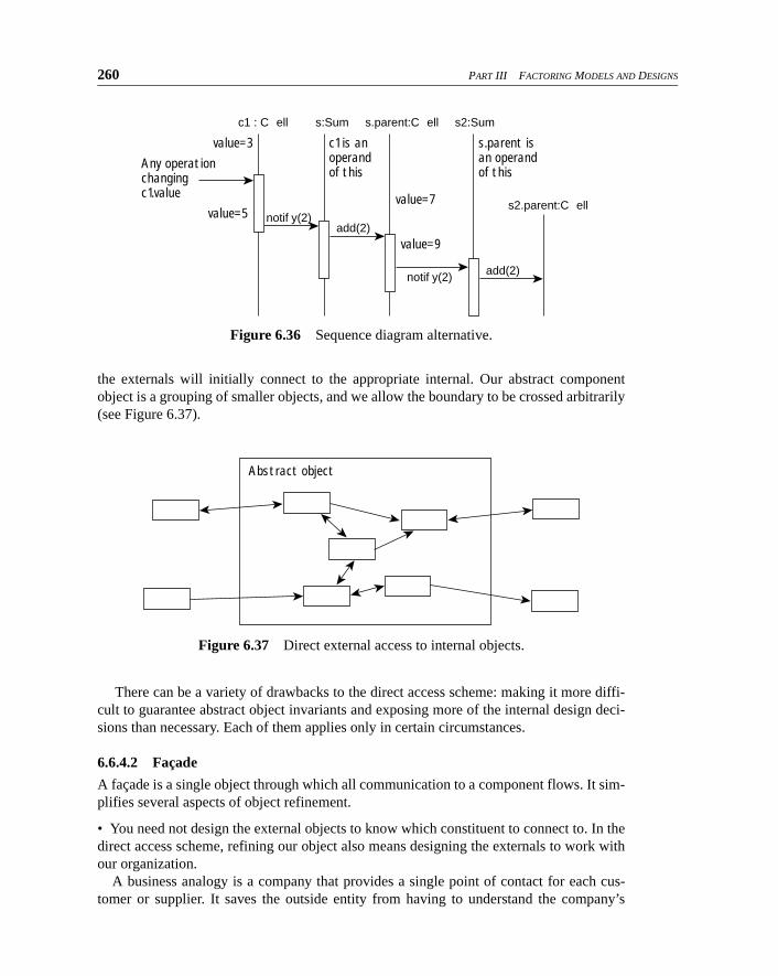
260 PART III FACTORING MODELS AND DESIGNS
the externals will initially connect to the appropriate internal. Our abstract componentobject is a grouping of smaller objects, and we allow the boundary to be crossed arbitrarily(see Figure 6.37).
There can be a variety of drawbacks to the direct access scheme: making it more diffi-cult to guarantee abstract object invariants and exposing more of the internal design deci-sions than necessary. Each of them applies only in certain circumstances.
6.6.4.2 Façade
A façade is a single object through which all communication to a component flows. It sim-plifies several aspects of object refinement.
• You need not design the external objects to know which constituent to connect to. In thedirect access scheme, refining our object also means designing the externals to work withour organization.
A business analogy is a company that provides a single point of contact for each cus-tomer or supplier. It saves the outside entity from having to understand the company’s
Figure 6.36 Sequence diagram alternative.
Figure 6.37 Direct external access to internal objects.
Any operationchangingc1.value
value=3
value=5value=7
value=9
c1 is anoperandof this
s.parent isan operandof this
c1 : C ell s:Sum s.parent:C ell
s2.parent:C ell
s2:Sum
add(2)notif y(2)
add(2)notif y(2)
Abstract object
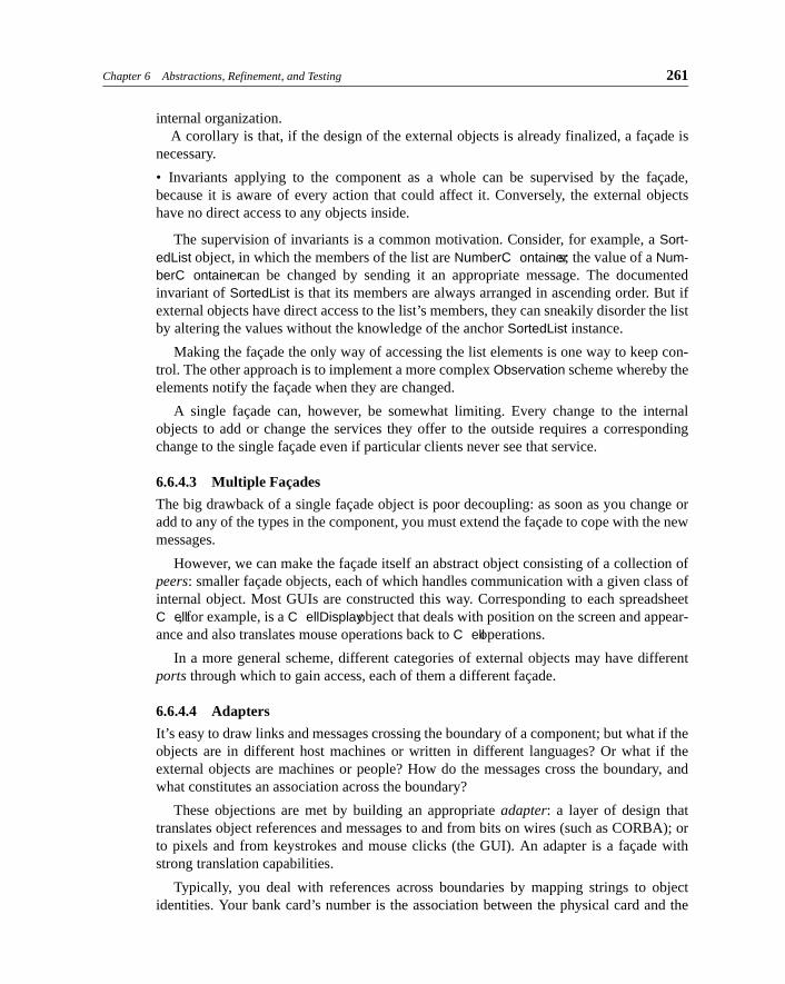
Chapter 6 Abstractions, Refinement, and Testing 261
internal organization.A corollary is that, if the design of the external objects is already finalized, a façade is
necessary.
• Invariants applying to the component as a whole can be supervised by the façade,because it is aware of every action that could affect it. Conversely, the external objectshave no direct access to any objects inside.
The supervision of invariants is a common motivation. Consider, for example, a Sort-edList object, in which the members of the list are NumberC ontainers; the value of a Num-berC ontainer can be changed by sending it an appropriate message. The documentedinvariant of SortedList is that its members are always arranged in ascending order. But ifexternal objects have direct access to the list’s members, they can sneakily disorder the listby altering the values without the knowledge of the anchor SortedList instance.
Making the façade the only way of accessing the list elements is one way to keep con-trol. The other approach is to implement a more complex Observation scheme whereby theelements notify the façade when they are changed.
A single façade can, however, be somewhat limiting. Every change to the internalobjects to add or change the services they offer to the outside requires a correspondingchange to the single façade even if particular clients never see that service.
6.6.4.3 Multiple Façades
The big drawback of a single façade object is poor decoupling: as soon as you change oradd to any of the types in the component, you must extend the façade to cope with the newmessages.
However, we can make the façade itself an abstract object consisting of a collection ofpeers: smaller façade objects, each of which handles communication with a given class ofinternal object. Most GUIs are constructed this way. Corresponding to each spreadsheetC ell, for example, is a C ellDisplay object that deals with position on the screen and appear-ance and also translates mouse operations back to C ell operations.
In a more general scheme, different categories of external objects may have differentports through which to gain access, each of them a different façade.
6.6.4.4 Adapters
It’s easy to draw links and messages crossing the boundary of a component; but what if theobjects are in different host machines or written in different languages? Or what if theexternal objects are machines or people? How do the messages cross the boundary, andwhat constitutes an association across the boundary?
These objections are met by building an appropriate adapter: a layer of design thattranslates object references and messages to and from bits on wires (such as CORBA); orto pixels and from keystrokes and mouse clicks (the GUI). An adapter is a façade withstrong translation capabilities.
Typically, you deal with references across boundaries by mapping strings to objectidentities. Your bank card’s number is the association between the physical card and the
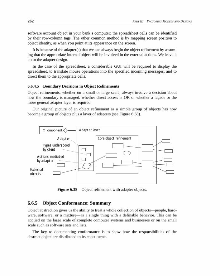
262 PART III FACTORING MODELS AND DESIGNS
software account object in your bank’s computer; the spreadsheet cells can be identifiedby their row-column tags. The other common method is by mapping screen position toobject identity, as when you point at its appearance on the screen.
It is because of the adapter(s) that we can always begin the object refinement by assum-ing that the appropriate internal object will be involved in the external actions. We leave itup to the adapter design.
In the case of the spreadsheet, a considerable GUI will be required to display thespreadsheet, to translate mouse operations into the specified incoming messages, and todirect them to the appropriate cells.
6.6.4.5 Boundary Decisions in Object Refinements
Object refinements, whether on a small or large scale, always involve a decision abouthow the boundary is managed: whether direct access is OK or whether a façade or themore general adapter layer is required.
Our original picture of an object refinement as a simple group of objects has nowbecome a group of objects plus a layer of adapters (see Figure 6.38).
6.6.5 Object Conformance: SummaryObject abstraction gives us the ability to treat a whole collection of objects—people, hard-ware, software, or a mixture—as a single thing with a definable behavior. This can beapplied on the large scale of complete computer systems and businesses or on the smallscale such as software sets and lists.
The key to documenting conformance is to show how the responsibilities of theabstract object are distributed to its constituents.
Figure 6.38 Object refinement with adapter objects.
Adapter layer
Adapter
Types understoodby client
Actions mediatedby adapter
Core object refinement
C omponent
Externalobjects
Chapter 6 Abstractions, Refinement, and Testing 263
6.7 Spreadsheet: Operation Refinement
Operation refinement means writing a program that fulfills a given pre/post (and/or rely/guarantee) specification. It is here that we finally get down to program code. In one sense,this is the part we need to say least about, because the point of this book is not to teach pro-gramming; you know how to put together loops and branches and sequences and can easilylearn any (far more verbose) graphical representations of the same. However, there are somespecial considerations, most of them about decoupling, which is what OO programming isall about.
6.7.1 What Operation Abstraction Means and Doesn’t MeanAn operation is a subtype of an action: operations are actions consisting of an invocationfrom a sender to a receiver, followed by an activity on the part of the receiver and possiblyending with a return signal to the sender. Operations are a one-sided view of the sender-receiver interaction.
If an operation is invoked in a situation when the precondition is false or if, during theexecution of the operation, its rely condition becomes false, then the specification does notstate what the outcome should be.
If an operation is invoked in a situation when the precondition is true and the rely con-dition is true throughout, then, by the end of the operation, the postcondition will havebeen achieved; and during the execution of the operation, the guarantee condition willhave been maintained.
Preconditions and rely conditions, by default, are “true” and there is no obligation onthe sender. Similarly, an empty postcondition or guarantee condition imposes no obliga-tion on the implementor.
The operation should not alter variables that could be left untouched while achievingthe postcondition and guarantee conditions.
Any invariant in the model should be considered to be ANDed to the pre- and the post-conditions (but not the rely and the guarantee conditions).
6.7.2 Strong DecouplingIn conventional programs, you split a big program into subroutines so that common rou-tines can be invoked individually and so that the program is easier to understand. In OOprogramming, the process goes even further. For every statement, you think, “Whichobject should this be attached to? Which object has the information and the other opera-tions most strongly relevant to this?” Then you send a message to the appropriate object.Actually, that’s not for every statement; rather, it’s for every subexpression.
The purpose is to ensure that the program is well decoupled. If the preceding stages ofdesign have gone well, many of these questions should be sorted out. However, you defi-
264 PART III FACTORING MODELS AND DESIGNS
nitely have more decisions to make in an OO development than in procedural develop-ment.
The choice of types for a local variable—temporaries, inputs, and even return values—for an operation is crucial to good decoupling. As soon as you declare a variable or param-eter that belongs to a particular class, you have made your part of the program dependenton that class. This means that any changes there may have an impact here. Instead, it isusually better to declare all variables as types; the only place in a program where youabsolutely must refer to a concrete class is to instantiate a new object.
There is a variety of powerful patterns to help reduce dependencies.
• Role decoupling: A variable or parameter contains an object or a reference to one. Fre-quently, the component in which the declaration occurs uses only some of the facilitiesprovided by that object.
Therefore, define a type (that is, an interface or pure abstract class plus a specification)that characterizes only the features that you will use. Declare the variable to be of thistype. Declare the object’s class to be an implementor of this type. This approach will min-imize the dependency of your component on the other object. Related patterns are adapterand bridge [Gamma94].
(Role decoupling is particularly important for two-way links.)
• Factory: An object must be created as a member of a definite class. This gives rise to adependency between your class and that one.
Therefore, devolve to a separate class the decision about which class the new objectshould belong to. By doing this, you encapsulate the class dependency behind a type-based creation method [Gamma95].
6.7.3 Documenting Operation Spec ConformanceWhether we have written it informally or in more precise form, we should have a specifi-cation of what is expected of each operation. We should attempt to check that the programcode of each operation conforms to what is expected of it.
The most reliable method is to turn the specs into test harnesses, as we discussed ear-lier. But there is also the Deep Thought approach: as a general principle, it is possible toinspect both specification and code and to check that one meets the other by a judiciousmixture of careful reasoning and guesswork. Although Deep Thought is not an economi-cal method of verification outside safety-critical circles, being aware of the basic princi-ples can help anyone root out obvious mistakes before getting to the testing stage.
There are two ways of fulfilling a spec. The hard way is to write the entire implementa-tion yourself. The easy way is to find something that comes close to already doing the joband possibly bend the requirements to suit what you’ve found. The latter is usually moreeconomical if you’re fairly confident of its provenance and integrity (see, for example,Section 10.11, Heterogenous Components).
Chapter 6 Abstractions, Refinement, and Testing 265
6.7.3.1 Comparing Two Operation Specs
Suppose we find some code in a library and we suspect that it does the job we require.Miraculously, it comes with a spec and model of some sort, which we want to compare toour requirements spec.
The rules for comparing two pre/post specs are as follows.
• Any invariants in each model should be ANDed with both pre- and postconditions writ-ten in that model.
• If the requirement has several pre- and postcondition pairs—which may come from
different supertypes—they should be ANDed in pairs ((pre1=>post1) AND
(pre2=>post2)) to give an overall requirement postcondition. If the pre- and postcon-ditions are not from supertypes and are subject to joining (see Section 8.3.4, Joining
Action Specifications), compose them accordingly.
• The implementation’s vocabulary should be translated to the specification’s by using
retrieve functions as in Section 6.4, Spreadsheet: Model Refinement.
• The precondition of the requirement should imply the precondition of the implementa-tion. For example, if the requirement says, “This operation should work whenever C ell
c contains a Number,” then an implementation that works “whenever c is non-Blank” is
fine because it is always true that “a C ell contains a Number => it is not Blank.”
• The postcondition of the implementation should imply the postcondition of the specifi-cation. (Notice that this is the other way around from preconditions, a feature called
contravariance.) So if the implementation claims that “this operation adds 3 to the
C ell’s value” whereas the requirement is more vague (“this operation should increase
the C ell’s value”), then we are OK, because it is always true that “3 added to value =>
value increased.”
6.7.3.2 Comparing Operation Specs with Code
More likely, you will have to compare your specification with code (whether you’ve writ-ten it yourself or someone else has). Again, the most effective strategy is to write test har-nesses, as we discussed before.8
In debug mode, preconditions should be written as tests performed on entry to an oper-ation; postconditions are tested on the way out. The only complication is that, becausepostconditions can contain @pre, you must save copies of those items while checking theprecondition. (Or you may be lucky enough to be using a language with this facility built-in.) The main caveat is to ensure that the pre- and postconditions don’t themselves changeanything.
If you prefer the Deep Thought approach, many (unfortunately, rather academic-sound-ing) books have been written on how to document this kind of refinement (for example,[Jones] and [Morgan]). The following summarizes the key points in a pragmatic way.
8. For more on the Deep Thought approach, see [Morgan88] or [Jones86]. For more on executing pre- and postconditions, see [Meyer88].
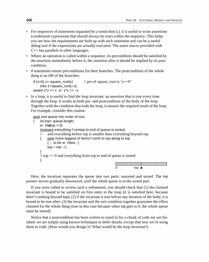
266 PART III FACTORING MODELS AND DESIGNS
• For sequences of statements separated by a semicolon (;), it is useful to write assertions
(conditional expressions that should always be true) within the sequence. This helps
you see how the requirements are built up with each statement and can be a useful debug tool if the expressions are actually executed. The assert macro provided with
C++ has parallels in other languages.
• Where an operation is called within a sequence, its precondition should be satisfied by
the assertion immediately before it; the assertion after it should be implied by its post-condition.
• If statements ensure preconditions for their branches. The postcondition of the whole
thing is an OR of the branches:
if (x>0) z= square_root(x) // pre of square_root is ‘x>=0’else z=square_root(–x);
assert z*z == x or z*z == –x
• In a loop, it is useful to find the loop invariant: an assertion that is true every time
through the loop. It works as both pre- and postcondition of the body of the loop. Together with the condition that ends the loop, it ensures the required result of the loop. For example, consider this routine:
post sort queue into order of size{ int top= queue.length;
w hile (top > 0)invariant everything f rom top to end of queue is sorted,// and everything before top is smaller than everything beyond top{ post move biggest of items f rom 0 to top along to top
{ ... to be w ritten ... }top = top –1;
}// top == 0 and everything from top to end of queue is sorted}
Here, the invariant separates the queue into two parts: unsorted and sorted. The toppointer moves gradually downward, until the whole queue is in the sorted part.
If you were called to review such a refinement, you should check that (1) the claimedinvariant is bound to be satisfied on first entry to the loop (it is satisfied here, becausethere’s nothing beyond top); (2) if the invariant is true before any iteration of the body, it isbound to be true after; (3) the invariant and the exit condition together guarantee the effectclaimed for the whole thing (true in this case because when top gets to 0, the whole queuemust be sorted).
Notice that a postcondition has been written to stand in for a chunk of code not yet fin-ished; we are simply using known techniques to defer details, except that now we’re usingthem in code. (How would you design it? What would be the loop invariant?)
0 top��
Chapter 6 Abstractions, Refinement, and Testing 267
6.7.3.3 Operation Conformance and Action Conformance: Differences
Both operation and action conformance show how a single action with an overall goal isreleased by a composition of smaller actions, and some of the techniques for establishingthe relationship are the same. The differences are summarized in Table 6.2.
6.7.4 Operation Conformance: SummaryOperation abstraction makes it possible to state what is required of an object withoutgoing into the detail of how the requirements are met. The implementation will use what-ever constructs are provided by the programming language, such as sequences, branches,and loops; it will choose its own set of variables and stored data. There are well-definedrules for verifying that the implementation meets the specification or, more pragmatically,systematic techniques for instrumenting and testing the implementation.
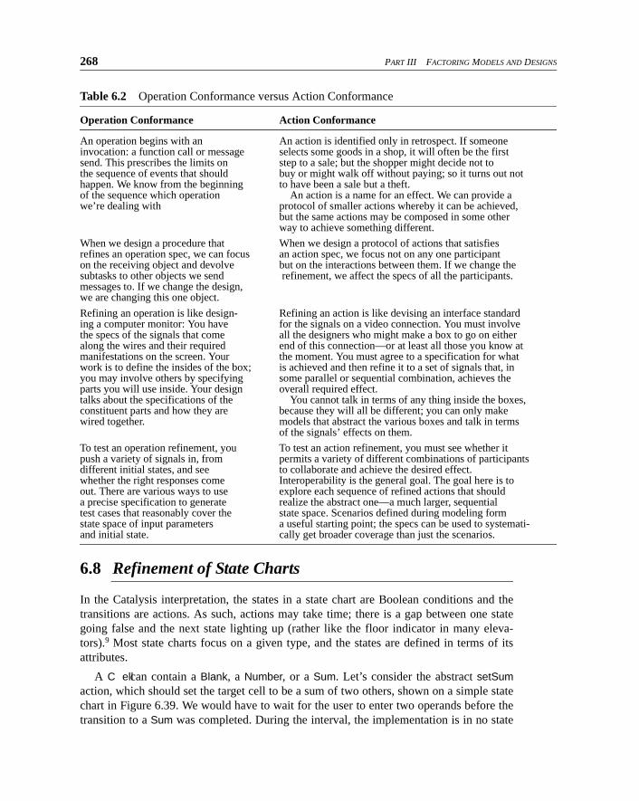
268 PART III FACTORING MODELS AND DESIGNS
Table 6.2 Operation Conformance versus Action Conformance
Operation Conformance Action Conformance
An operation begins with an An action is identified only in retrospect. If someoneinvocation: a function call or message selects some goods in a shop, it will often be the firstsend. This prescribes the limits on step to a sale; but the shopper might decide not tothe sequence of events that should buy or might walk off without paying; so it turns out nothappen. We know from the beginning to have been a sale but a theft.of the sequence which operation An action is a name for an effect. We can provide awe’re dealing with protocol of smaller actions whereby it can be achieved,
but the same actions may be composed in some other way to achieve something different.
When we design a procedure that When we design a protocol of actions that satisfiesrefines an operation spec, we can focus an action spec, we focus not on any one participanton the receiving object and devolve but on the interactions between them. If we change thesubtasks to other objects we send refinement, we affect the specs of all the participants.messages to. If we change the design,we are changing this one object.
Refining an operation is like design- Refining an action is like devising an interface standarding a computer monitor: You have for the signals on a video connection. You must involvethe specs of the signals that come all the designers who might make a box to go on eitheralong the wires and their required end of this connection—or at least all those you know atmanifestations on the screen. Your the moment. You must agree to a specification for whatwork is to define the insides of the box; is achieved and then refine it to a set of signals that, inyou may involve others by specifying some parallel or sequential combination, achieves theparts you will use inside. Your design overall required effect. talks about the specifications of the You cannot talk in terms of any thing inside the boxes,constituent parts and how they are because they will all be different; you can only makewired together. models that abstract the various boxes and talk in terms
of the signals’ effects on them.
To test an operation refinement, you To test an action refinement, you must see whether itpush a variety of signals in, from permits a variety of different combinations of participantsdifferent initial states, and see to collaborate and achieve the desired effect.whether the right responses come Interoperability is the general goal. The goal here is toout. There are various ways to use explore each sequence of refined actions that shoulda precise specification to generate realize the abstract one—a much larger, sequentialtest cases that reasonably cover the state space. Scenarios defined during modeling formstate space of input parameters a useful starting point; the specs can be used to systemati-and initial state. cally get broader coverage than just the scenarios.
6.8 Refinement of State Charts
In the Catalysis interpretation, the states in a state chart are Boolean conditions and thetransitions are actions. As such, actions may take time; there is a gap between one stategoing false and the next state lighting up (rather like the floor indicator in many eleva-tors).9 Most state charts focus on a given type, and the states are defined in terms of itsattributes.
A C ell can contain a Blank, a Number, or a Sum. Let’s consider the abstract setSumaction, which should set the target cell to be a sum of two others, shown on a simple statechart in Figure 6.39. We would have to wait for the user to enter two operands before thetransition to a Sum was completed. During the interval, the implementation is in no state
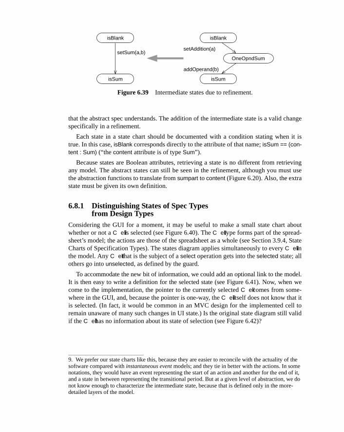
Chapter 6 Abstractions, Refinement, and Testing 269
that the abstract spec understands. The addition of the intermediate state is a valid changespecifically in a refinement.
Each state in a state chart should be documented with a condition stating when it istrue. In this case, isBlank corresponds directly to the attribute of that name; isSum == (con-tent : Sum) (“the content attribute is of type Sum”).
Because states are Boolean attributes, retrieving a state is no different from retrievingany model. The abstract states can still be seen in the refinement, although you must usethe abstraction functions to translate from sumpart to content (Figure 6.20). Also, the extrastate must be given its own definition.
6.8.1 Distinguishing States of Spec Types from Design Types
Considering the GUI for a moment, it may be useful to make a small state chart aboutwhether or not a C ell is selected (see Figure 6.40). The C ell type forms part of the spread-sheet’s model; the actions are those of the spreadsheet as a whole (see Section 3.9.4, StateCharts of Specification Types). The states diagram applies simultaneously to every C ell inthe model. Any C ell that is the subject of a select operation gets into the selected state; allothers go into unselected, as defined by the guard.
To accommodate the new bit of information, we could add an optional link to the model.It is then easy to write a definition for the selected state (see Figure 6.41). Now, when wecome to the implementation, the pointer to the currently selected C ell comes from some-where in the GUI, and, because the pointer is one-way, the C ell itself does not know that itis selected. (In fact, it would be common in an MVC design for the implemented cell toremain unaware of many such changes in UI state.) Is the original state diagram still validif the C ell has no information about its state of selection (see Figure 6.42)?
9. We prefer our state charts like this, because they are easier to reconcile with the actuality of the software compared with instantaneous event models; and they tie in better with the actions. In some notations, they would have an event representing the start of an action and another for the end of it, and a state in between representing the transitional period. But at a given level of abstraction, we do not know enough to characterize the intermediate state, because that is defined only in the more-detailed layers of the model.
Figure 6.39 Intermediate states due to refinement.
isBlank
isSum
setSum(a,b)
isBlank
isSum
OneOpndSum
setAddition(a)
addOperand(b)
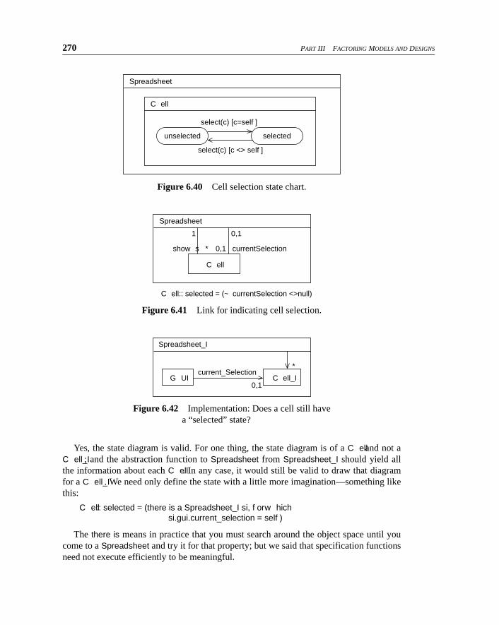
270 PART III FACTORING MODELS AND DESIGNS
Yes, the state diagram is valid. For one thing, the state diagram is of a C ell and not aC ell_I; and the abstraction function to Spreadsheet from Spreadsheet_I should yield allthe information about each C ell. In any case, it would still be valid to draw that diagramfor a C ell_I. We need only define the state with a little more imagination—something likethis:
C ell :: selected = (there is a Spreadsheet_I si, f or w hichsi.gui.current_selection = self )
The there is means in practice that you must search around the object space until youcome to a Spreadsheet and try it for that property; but we said that specification functionsneed not execute efficiently to be meaningful.
Figure 6.40 Cell selection state chart.
Figure 6.41 Link for indicating cell selection.
Figure 6.42 Implementation: Does a cell still have
a “selected” state?
Spreadsheet
C ell
unselected selected
select(c) [c=self ]
select(c) [c <> self ]
Spreadsheet
C ell
1 0,1
0,1 currentSelectionshow s *
C ell:: selected = (~ currentSelection <>null)
C ell_IG UI0,1
current_Selection*
Spreadsheet_I
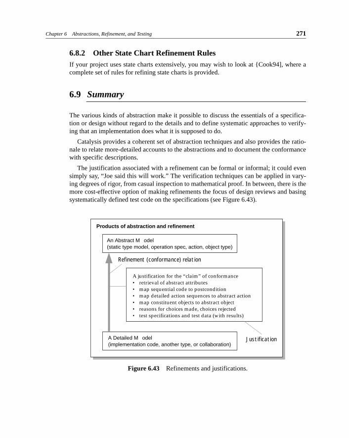
Chapter 6 Abstractions, Refinement, and Testing 271
6.8.2 Other State Chart Refinement RulesIf your project uses state charts extensively, you may wish to look at {Cook94], where acomplete set of rules for refining state charts is provided.
6.9 Summary
The various kinds of abstraction make it possible to discuss the essentials of a specifica-tion or design without regard to the details and to define systematic approaches to verify-ing that an implementation does what it is supposed to do.
Catalysis provides a coherent set of abstraction techniques and also provides the ratio-nale to relate more-detailed accounts to the abstractions and to document the conformancewith specific descriptions.
The justification associated with a refinement can be formal or informal; it could evensimply say, “Joe said this will work.” The verification techniques can be applied in vary-ing degrees of rigor, from casual inspection to mathematical proof. In between, there is themore cost-effective option of making refinements the focus of design reviews and basingsystematically defined test code on the specifications (see Figure 6.43).
Figure 6.43 Refinements and justifications.
Products of abstraction and refinement
An Abstract M odel(static type model, operation spec, action, object type)
A Detailed M odel(implementation code, another type, or collaboration)
Refinement (conformance) relation
A justification for the “claim” of conformance• retrieval of abstract attributes• map sequential code to postcondition• map detailed action sequences to abstract action• map constituent objects to abstract object• reasons for choices made, choices rejected• test specifications and test data (with results)
Justification
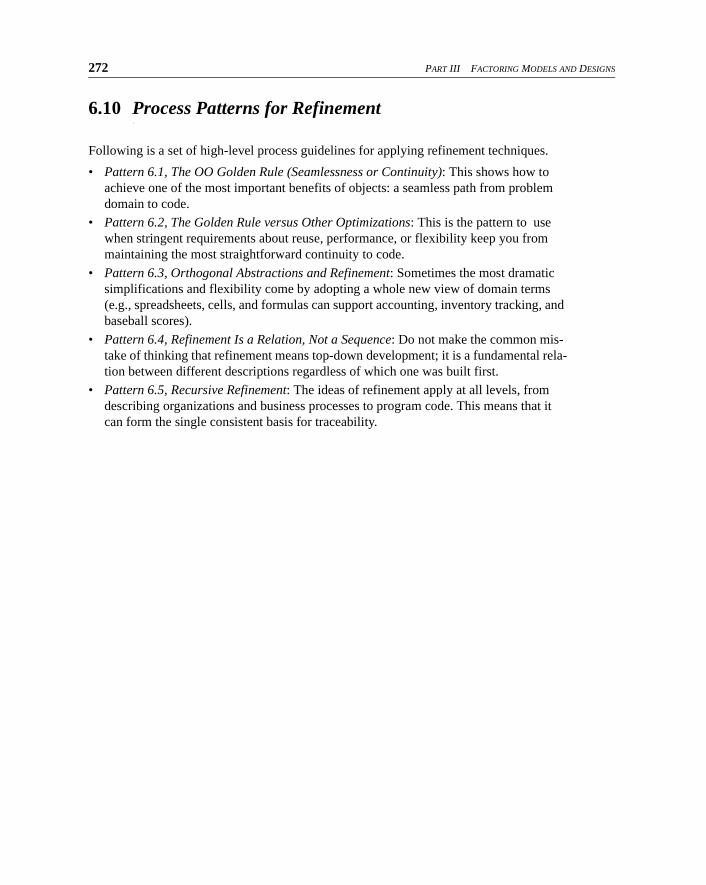
272 PART III FACTORING MODELS AND DESIGNS
6.10 Process Patterns for Refinement
Following is a set of high-level process guidelines for applying refinement techniques.
• Pattern 6.1, The OO Golden Rule (Seamlessness or Continuity): This shows how to
achieve one of the most important benefits of objects: a seamless path from problem
domain to code.
• Pattern 6.2, The Golden Rule versus Other Optimizations: This is the pattern to use
when stringent requirements about reuse, performance, or flexibility keep you from
maintaining the most straightforward continuity to code.
• Pattern 6.3, Orthogonal Abstractions and Refinement: Sometimes the most dramatic
simplifications and flexibility come by adopting a whole new view of domain terms
(e.g., spreadsheets, cells, and formulas can support accounting, inventory tracking, and
baseball scores).
• Pattern 6.4, Refinement Is a Relation, Not a Sequence: Do not make the common mis-take of thinking that refinement means top-down development; it is a fundamental rela-tion between different descriptions regardless of which one was built first.
• Pattern 6.5, Recursive Refinement: The ideas of refinement apply at all levels, from
describing organizations and business processes to program code. This means that it can form the single consistent basis for traceability.
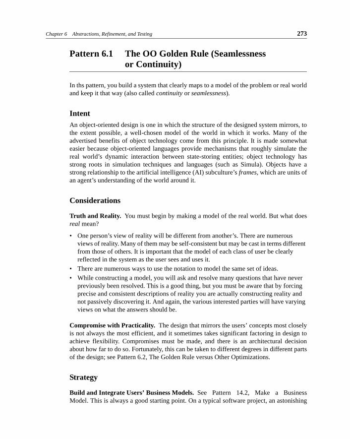
Chapter 6 Abstractions, Refinement, and Testing 273
Pattern 6.1 The OO Golden Rule (Seamlessness or Continuity)
In ths pattern, you build a system that clearly maps to a model of the problem or real worldand keep it that way (also called continuity or seamlessness).
IntentAn object-oriented design is one in which the structure of the designed system mirrors, tothe extent possible, a well-chosen model of the world in which it works. Many of theadvertised benefits of object technology come from this principle. It is made somewhateasier because object-oriented languages provide mechanisms that roughly simulate thereal world’s dynamic interaction between state-storing entities; object technology hasstrong roots in simulation techniques and languages (such as Simula). Objects have astrong relationship to the artificial intelligence (AI) subculture’s frames, which are units ofan agent’s understanding of the world around it.
Considerations
Truth and Reality. You must begin by making a model of the real world. But what doesreal mean?
• One person’s view of reality will be different from another’s. There are numerous
views of reality. Many of them may be self-consistent but may be cast in terms different from those of others. It is important that the model of each class of user be clearly
reflected in the system as the user sees and uses it.
• There are numerous ways to use the notation to model the same set of ideas.
• While constructing a model, you will ask and resolve many questions that have never previously been resolved. This is a good thing, but you must be aware that by forcing
precise and consistent descriptions of reality you are actually constructing reality and
not passively discovering it. And again, the various interested parties will have varying
views on what the answers should be.
Compromise with Practicality. The design that mirrors the users’ concepts most closelyis not always the most efficient, and it sometimes takes significant factoring in design toachieve flexibility. Compromises must be made, and there is an architectural decisionabout how far to do so. Fortunately, this can be taken to different degrees in different partsof the design; see Pattern 6.2, The Golden Rule versus Other Optimizations.
Strategy
Build and Integrate Users’ Business Models. See Pattern 14.2, Make a BusinessModel. This is always a good starting point. On a typical software project, an astonishing
274 PART III FACTORING MODELS AND DESIGNS
number of downstream problems can be prevented by clarifying and building a clearvocabulary of the problem domain.
Cast System Requirements in Terms of the Business Model. See Pattern 15.7, Construct aSystem Behavior Spec. Particularly if the domain model has been clearly defined, systemrequirements can be discussed, understood, and decided far more precisely.
Choose Classes Based on the Business Model. To maintain traceability, deviationsforced by performance, current or planned reuse, and other constraints should be local andclearly documented as refinements.
Maintain Development Layers (Business Model to Code) in Step. This strategy clearlyconflicts with the usual short-term imperative of getting changes done immediately anddirectly in the code; but a clear separation of domain, system, and technology infrastruc-ture descriptions (and code) helps localize changes, and experience shows clear, long-termbenefits. Furthermore, because the documents are more abstract as you go up the tree, youcome to a point where there is no change. Performance improvements, for example, usu-ally change the code but perhaps not the requirements or the model in which they areexpressed; or some design refactoring for reuse and flexibility may have no effect on theexternal spec, affecting only the refinement and its associated mapping.
Build Many Projects on the Same Model. A problem domain model is useful acrossmore than a single project. But don’t take this as a reason for perfecting a model beforebuilding your first system; see Pattern 14.2, Make a Business Model.
BenefitsMany of the advertised benefits of object technology come from this pattern.
• The resulting system relates better to the end users because it deals in the terms they are
familiar with (assuming a reasonable problem domain model) and traces back to the
business tasks they perform.
• Making changes is easier because users express their requirements in terms that are
easy to trace through to the model and implementation. In a good problem domain
model, things are factored so that common requirements changes do not cause massive
model updates; the design should reflect this structure.
• The same business model can be used for many projects within the same business. As a
result, more of the code can also be generalized and reused.
Chapter 6 Abstractions, Refinement, and Testing 275
Pattern 6.2 The Golden Rule versus Other Optimizations
Consciously tradeoff performance, reuse, and flexibility optimization against entirelyseamless design; document a refinement clearly whenever you must stray significantlyfrom a pristine domain model.
IntentIn an ideal sense, the structure of the design could be based directly on a model of theworld in which it works (to an appropriate extent). Performance, flexibility, and reuse con-straints sometimes dictate against naive continuity, and elements from architectural designdown may need to differ from a real-world model. The question is how to balance thegoals of seamlessness, maintainability, reuse, and tuned performance.
ConsiderationsWill the program code be object-oriented? If it is, should we choose the classes directlyfrom the domain model or based on design patterns or following the gut instincts of theproject guru?
Mirroring a good model of the world in your code is good for simulations: Every timeyou change your picture of the world, you can more easily find which parts of the simula-tion code to change. This is how OOP originated with the Simula language.
The flexibility provided by polymorphism and dynamic binding in an OOP language,combined with a well-factored design, makes it better suited for writing any kind of pro-gram whose requirements change regularly—that is, almost all of them. (It’s been esti-mated that 70% to 80% of total spending in a program’s life cycle is in the maintenancephase after first delivery.) However, we gain this flexibility at the cost of making manyextra decisions about which object should take responsibility for each small part of thejob—something that is often not obvious from the problem domain model itself—and atthe cost to runtime performance of all those objects passing control to one another. Theformer can make a difference in initial project development time; the latter can make a bigdifference in performance-critical real-time control software such as communications oravionics.
Moreover, there is little flexibility and reuse at the level of individual problem domainobjects. Each object plays roles in different collaborations; a far more likely unit of reuseis the collaboration or its manifestation as a framework in code (see Chapter 11, Reuse andPluggable Design: Frameworks in Code).
Code that makes miraculous-seeming leaps from the domain vocabulary into designdecisions, even if based on the best gut instincts, will not retain its intended form for long.
Flexibility comes from decoupling: making components independent of one another.Optimization for performance generally means that pieces of code that were ideallydecoupled become dependent on one another’s details. So the more you optimize, the
276 PART III FACTORING MODELS AND DESIGNS
more you mix concerns that were independent before. In the extreme, you end up with atraditional monolithic program.
StrategyMake an early architectural decision about how much you will tradeoff performance,seamlessness, reuse, code flexibility, and so on. If your clients shout for little functionalenhancements every day (something that is typical for in-house financial trading soft-ware), optimize the underlying communications and infrastructure but leave the businessmodel pristine. But if your software will be embedded in a million car engines for 10years, optimize for performance.
Eighty percent of the execution is done by 20% of the code. Design your system in astraightforward object-mirroring way and then abstract and re-refine the pieces that aremost critical to performance. (Or analyze a prototype and worry about the executionhotspots.) See Pattern 15.12, Avoid Miracles, Refine the Spec.
Buy faster hardware and more memory. They’re much cheaper than programmers.
BenefitsAn OO program is one that is refined from an OO design. A clearly defined refinementcarries a retrieval that relates it to the abstraction even when the design has been optimizedfrom a real-world abstraction.
Chapter 6 Abstractions, Refinement, and Testing 277
Pattern 6.3 Orthogonal Abstractions and Refinement
Sometimes the greatest improvements in reuse and flexibility come by adopting a signifi-cantly more abstract (or even orthogonal) view of problem domain terms. Use refinementand frameworks so that you don’t lose traceability to domain terms.
IntentGain flexibility by using orthogonal abstract views of different parts of the problem, butretain traceability to the straightforward domain terms.
ConsiderationsYou get only so much reuse and flexibility by adopting the most straightforward model ofthe problem domain. The terms have evolved to be specific to that domain and may beinconsistent with terms used elsewhere.
Consider a couple of examples. First, in an application for supporting a seminar busi-ness, we need to schedule instructors and rooms for seminar sessions; track customer pref-erences and trends to better target our marketing efforts; and maintain a stock of coursematerials, producing new ones as needed. Although we could analyze this problem in itssimplest domain terms, there would be much more opportunity for reuse if we character-ized the problem in an abstract, orthogonal way as follows: Assign resources (instructors,rooms) to jobs (seminar sessions); track customer trends for different products (seminartopics); and maintain a just-in-time inventory of items (course notes) of our products(seminar topics). Note that our requirements are now much more generic, merely special-ized to our domain specifics. (This example is worked out in more detail inSection 11.4.1.1, Combining Model Frameworks.)
Second, in an application for processing credit cards at a gas station, there are manyvariations in choices (paying outside versus paying inside), in product offerings (optionalcar wash or discount items), and in sequences of interactions with the user and the remotefinancial hosts. We could tackle some of this variability by appropriate design of types andclass hierarchies; however, we gain the biggest increase in flexibility when we recognizethat we should reify the steps in the card processing (product offerings, payment authori-zation, amount entry) from the sequences in which these steps are executed. If we build anexplicit representation of sequencing and other dependencies, we could even use a genericPetri Net interpreter as an abstract machine for handling arbitrary sequences and depen-dencies.
However, code that makes miraculous-seeming leaps from the domain vocabulary intodesign decisions, even if based on the best gut instincts, becomes irreversibly deformed bythe first few modifications made by a new programmer.
278 PART III FACTORING MODELS AND DESIGNS
StrategyDo not lose sight of the domain terms even in your code. Use refinement to maintain trace-ability even as your code becomes more decoupled and reusable. Wherever possible,recast the problem domain descriptions themselves using these orthogonal and moreabstract views; remember, you are actively constructing a model of reality and not pas-sively discovering it. Use frameworks (see Chapter 9, Model Frameworks and TemplatePackages) to explicitly document the mapping from domain terms to terms and roles in theabstract problem descriptions.
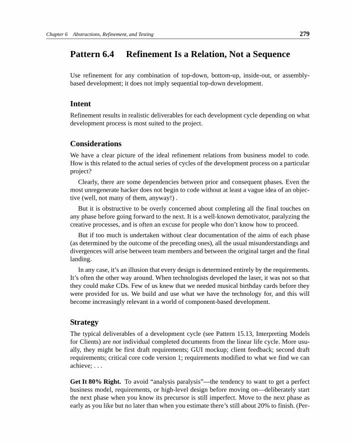
Chapter 6 Abstractions, Refinement, and Testing 279
Pattern 6.4 Refinement Is a Relation, Not a Sequence
Use refinement for any combination of top-down, bottom-up, inside-out, or assembly-based development; it does not imply sequential top-down development.
IntentRefinement results in realistic deliverables for each development cycle depending on whatdevelopment process is most suited to the project.
ConsiderationsWe have a clear picture of the ideal refinement relations from business model to code.How is this related to the actual series of cycles of the development process on a particularproject?
Clearly, there are some dependencies between prior and consequent phases. Even themost unregenerate hacker does not begin to code without at least a vague idea of an objec-tive (well, not many of them, anyway!) .
But it is obstructive to be overly concerned about completing all the final touches onany phase before going forward to the next. It is a well-known demotivator, paralyzing thecreative processes, and is often an excuse for people who don’t know how to proceed.
But if too much is undertaken without clear documentation of the aims of each phase(as determined by the outcome of the preceding ones), all the usual misunderstandings anddivergences will arise between team members and between the original target and the finallanding.
In any case, it’s an illusion that every design is determined entirely by the requirements.It’s often the other way around. When technologists developed the laser, it was not so thatthey could make CDs. Few of us knew that we needed musical birthday cards before theywere provided for us. We build and use what we have the technology for, and this willbecome increasingly relevant in a world of component-based development.
StrategyThe typical deliverables of a development cycle (see Pattern 15.13, Interpreting Modelsfor Clients) are not individual completed documents from the linear life cycle. More usu-ally, they might be first draft requirements; GUI mockup; client feedback; second draftrequirements; critical core code version 1; requirements modified to what we find we canachieve; . . .
Get It 80% Right. To avoid “analysis paralysis”—the tendency to want to get a perfectbusiness model, requirements, or high-level design before moving on—deliberately startthe next phase when you know its precursor is still imperfect. Move to the next phase asearly as you like but no later than when you estimate there’s still about 20% to finish. (Per-
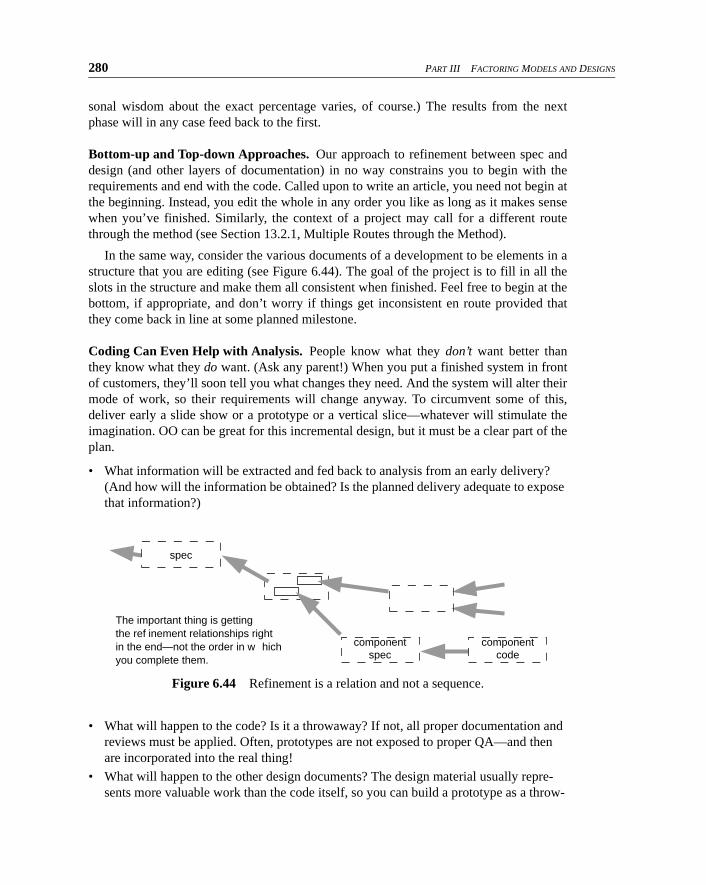
280 PART III FACTORING MODELS AND DESIGNS
sonal wisdom about the exact percentage varies, of course.) The results from the nextphase will in any case feed back to the first.
Bottom-up and Top-down Approaches. Our approach to refinement between spec anddesign (and other layers of documentation) in no way constrains you to begin with therequirements and end with the code. Called upon to write an article, you need not begin atthe beginning. Instead, you edit the whole in any order you like as long as it makes sensewhen you’ve finished. Similarly, the context of a project may call for a different routethrough the method (see Section 13.2.1, Multiple Routes through the Method).
In the same way, consider the various documents of a development to be elements in astructure that you are editing (see Figure 6.44). The goal of the project is to fill in all theslots in the structure and make them all consistent when finished. Feel free to begin at thebottom, if appropriate, and don’t worry if things get inconsistent en route provided thatthey come back in line at some planned milestone.
Coding Can Even Help with Analysis. People know what they don’t want better thanthey know what they do want. (Ask any parent!) When you put a finished system in frontof customers, they’ll soon tell you what changes they need. And the system will alter theirmode of work, so their requirements will change anyway. To circumvent some of this,deliver early a slide show or a prototype or a vertical slice—whatever will stimulate theimagination. OO can be great for this incremental design, but it must be a clear part of theplan.
• What information will be extracted and fed back to analysis from an early delivery?
(And how will the information be obtained? Is the planned delivery adequate to expose
that information?)
• What will happen to the code? Is it a throwaway? If not, all proper documentation and
reviews must be applied. Often, prototypes are not exposed to proper QA—and then
are incorporated into the real thing!
• What will happen to the other design documents? The design material usually repre-sents more valuable work than the code itself, so you can build a prototype as a throw-
Figure 6.44 Refinement is a relation and not a sequence.
spec
componentspec
componentcode
The important thing is gettingthe ref inement relationships rightin the end—not the order in w hichyou complete them.

Chapter 6 Abstractions, Refinement, and Testing 281
away even in some other language. This assumes that, as a reader of this book, you’re
documenting the design in some form other than the code.
282 PART III FACTORING MODELS AND DESIGNS
Pattern 6.5 Recursive Refinement
Establish a traceable relationship, based on refinement, between the most abstract specand the detailed implementation (program code).
IntentThe abstract spec should bear a systematic relationship to the code, and this relationshipshould be expressed as a series of refinements. Many of these are decompositions, whichbreak the problem into smaller pieces.
We wish to document the outcome of design.
Strategy• Model separate views. Rather than build a single monolithic model, recognize whenthere are useful different external views of your component. Model each such view sepa-rately so that the model relates seamlessly to that part of the problem domain.
• Compose views into one spec. When designing, it helps to have a single combined specon which you base your design; then you refine, and map to, only that single specification.Hence, compose your views into a single spec that you relate to your design and imple-mentation.
• Refine the spec using one of the standard refinements. Some refinements are one-to-one; others are decompositions. The latter split the spec into several separate ones, each ofwhich can be dealt with as a separate goal.
• Document each decomposition with a refinement that states how the constituents worktogether to fulfill the abstract spec.
• Each decomposition divides the job into a set of constituents, each with a specificationthat can be fulfilled separately. The same principles can be applied recursively to itsdesign. Thus, you can specify an entire application as a type and then decompose it intointernal collaborating components. If the components are of a nontrivial size, recursivelymodel and specify each of them as a type.
• “Basic design” shortcuts some of the recursive refinement process by going straight fora set of decisions that accept the specification types as protoclasses. A judicious combina-tion of basic design, subsequent optimization, and recursive refinement is practical formany projects.
• Use frameworks to build specifications and designs as well as refinements between thetwo. Frameworks (see Chapter 9, Model Frameworks and Template Packages) capturerecurring patterns of types, collaborations, and refinements. Used properly and with theright tool support, frameworks let you document the main refinement decisions in a singleplace rather than duplicate them each place they are used. A single framework namedCache could have the design and refinement rationale independently of the many differentcontexts in which it is used.

Chapter 6 Abstractions, Refinement, and Testing 283
ResultThe result is a design that is traceable through the refinements.

284 PART III FACTORING MODELS AND DESIGNS

![Research Article Compositional Abstraction Refinement for ...of state explosion in concurrent model checking, especially in conjunction with abstraction. e work in [ , ]pro-posed an](https://static.fdocuments.in/doc/165x107/6103fcc92c99d430a32a767e/research-article-compositional-abstraction-refinement-for-of-state-explosion.jpg)


![Thread-modular Abstraction Refinement Tom Henzinger Ranjit Jhala Rupak Majumdar [UC Berkeley] Shaz Qadeer [Microsoft Research]](https://static.fdocuments.in/doc/165x107/56649d405503460f94a1aa02/thread-modular-abstraction-refinement-tom-henzinger-ranjit-jhala-rupak-majumdar.jpg)