Chapter 5: The Data Link Layer
114
5: DataLink Layer 5-1 Chapter 5: The Data Link Layer Our goals: understand principles behind data link layer services: error detection, correction sharing a broadcast channel: multiple access link layer addressing reliable data transfer, flow control: done! instantiation and implementation of various link layer technologies
-
Upload
hayfa-david -
Category
Documents
-
view
38 -
download
5
description
Our goals: understand principles behind data link layer services: error detection, correction sharing a broadcast channel: multiple access link layer addressing reliable data transfer, flow control: done! instantiation and implementation of various link layer technologies. - PowerPoint PPT Presentation
Transcript of Chapter 5: The Data Link Layer
5: DataLink Layer 5-1
Chapter 5: The Data Link Layer
Our goals: understand principles behind data link layer
services: error detection, correction sharing a broadcast channel: multiple access link layer addressing reliable data transfer, flow control: done!
instantiation and implementation of various link layer technologies
5: DataLink Layer 5-2
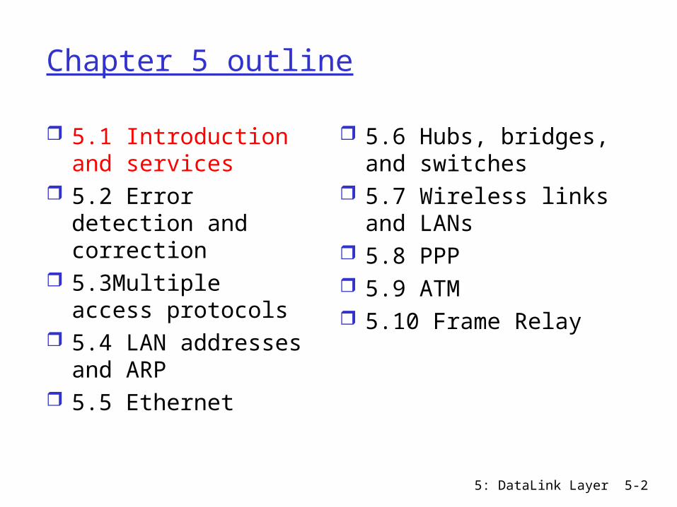
Chapter 5 outline
5.1 Introduction and services
5.2 Error detection and correction
5.3Multiple access protocols
5.4 LAN addresses and ARP
5.5 Ethernet
5.6 Hubs, bridges, and switches
5.7 Wireless links and LANs
5.8 PPP 5.9 ATM 5.10 Frame Relay

5: DataLink Layer 5-3
Link Layer: Introduction
Some terminology: hosts and routers are nodes communication channels that
connect adjacent nodes along communication path are links wired links wireless links LANs
2-PDU is a frame, encapsulates datagram
“link”
data-link layer has responsibility of transferring datagram from one node to adjacent node over a link
5: DataLink Layer 5-4
Link layer: context
Datagram transferred by different link protocols over different links: e.g., Ethernet on first link, frame relay on
intermediate links, 802.11 on last link
Each link protocol provides different services e.g., may or may not provide reliable data transfer
over link
5: DataLink Layer 5-5
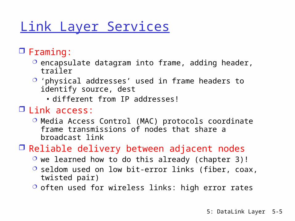
Link Layer Services
Framing: encapsulate datagram into frame, adding header,
trailer ‘physical addresses’ used in frame headers to identify
source, dest • different from IP addresses!
Link access: Media Access Control (MAC) protocols coordinate frame
transmissions of nodes that share a broadcast link Reliable delivery between adjacent nodes
we learned how to do this already (chapter 3)! seldom used on low bit-error links (fiber, coax, twisted
pair) often used for wireless links: high error rates

5: DataLink Layer 5-6
Link Layer Services (more) Flow Control:
pacing between adjacent sending and receiving nodes
Error Detection: errors caused by signal attenuation, noise. sender includes error-detection bits in frame receiver detects presence of errors:
• signals sender for retransmission or drops frame
Error Correction: receiver identifies and corrects bit error(s) without
resorting to retransmission Half-duplex and full-duplex
with half duplex, nodes at both ends of link can transmit, but not at same time

5: DataLink Layer 5-7
Adaptors Communicating
link layer implemented in “adaptor” (aka NIC) Ethernet card, 802.11 card
sending side: encapsulates datagram in
a frame adds error checking bits,
rdt, flow control, random access, etc.
receiving side error checking, rdt, flow
control, random access, etc
extracts datagram, passes to network layer
sendingnode
frame
rcvingnode
datagram
frame
adapter adapter
link layer protocol
5: DataLink Layer 5-8
Chapter 5 outline
5.1 Introduction and services
5.2 Error detection and correction
5.3Multiple access protocols
5.4 LAN addresses and ARP
5.5 Ethernet
5.6 Hubs, bridges, and switches
5.7 Wireless links and LANs
5.8 PPP 5.9 ATM 5.10 Frame Relay
5: DataLink Layer 5-9
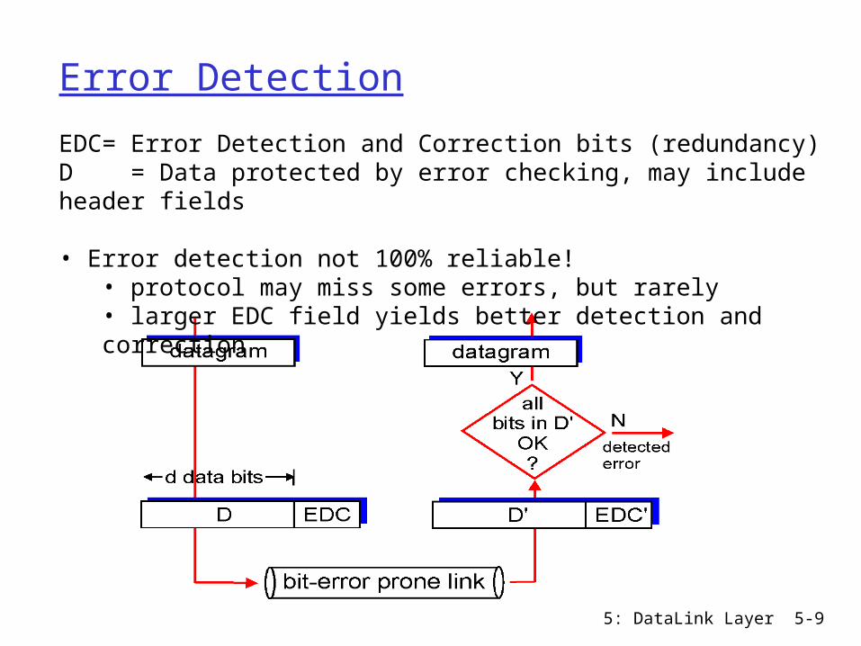
Error Detection
EDC= Error Detection and Correction bits (redundancy)D = Data protected by error checking, may include header fields
• Error detection not 100% reliable!• protocol may miss some errors, but rarely• larger EDC field yields better detection and correction

5: DataLink Layer 5-10
Parity Check
Example of even parity0111000110101011 1
Two Dimensional Parity Bit:Detect and correct single bit errors
d data bits
parity bit
Single Parity Bit: suppose d bits of data even/odd parity: add one
additional bit such that the total number of 1’s in the d+1 bits is even/odd
can detect an odd number of bit errors; can not detect an even number of bit errors
o o

5: DataLink Layer 5-11
Internet checksum (RFC 1071)
Sender: treat data as sequence of
16-bit integers compute 1’s complement
sum of data add carry-out (17th bit)
back into the lowest significant bit
put 1's complement of the sum into checksum field
Receiver: compute 1’s complement sum
of received data, including the checksum field
check if the result contains all 1 bits: NO - error detected YES - no error detected;
but may be errors nonetheless.
Goal: detect “errors” (e.g., flipped bits) in transmitted segment (used at transport layer)

5: DataLink Layer 5-12
Cyclic Redundancy Check (CRC)
often used in link layer view data bits, D, as a binary number sender, receiver agree on an r+1 bit pattern
(generator), G, leftmost bit of G must be 1 goal: choose r CRC bits, R, such that
<D,R> exactly divisible by G (modulo 2) receiver knows G, divides <D,R> by G. If non-zero
remainder: error detected!

5: DataLink Layer 5-13
CRC Example
Want:D.2r XOR R = nG
equivalently:D.2r = nG XOR R
equivalently: if we divide D.2r by G,
remainder is R
R = remainder[ ]D.2r
G
Example: D=101110, G=1001, r=3
In CRC calculations, addition and subtraction are equivalent to bitwise exclusive-or (XOR) Sender transmit: 101110 011
5: DataLink Layer 5-14
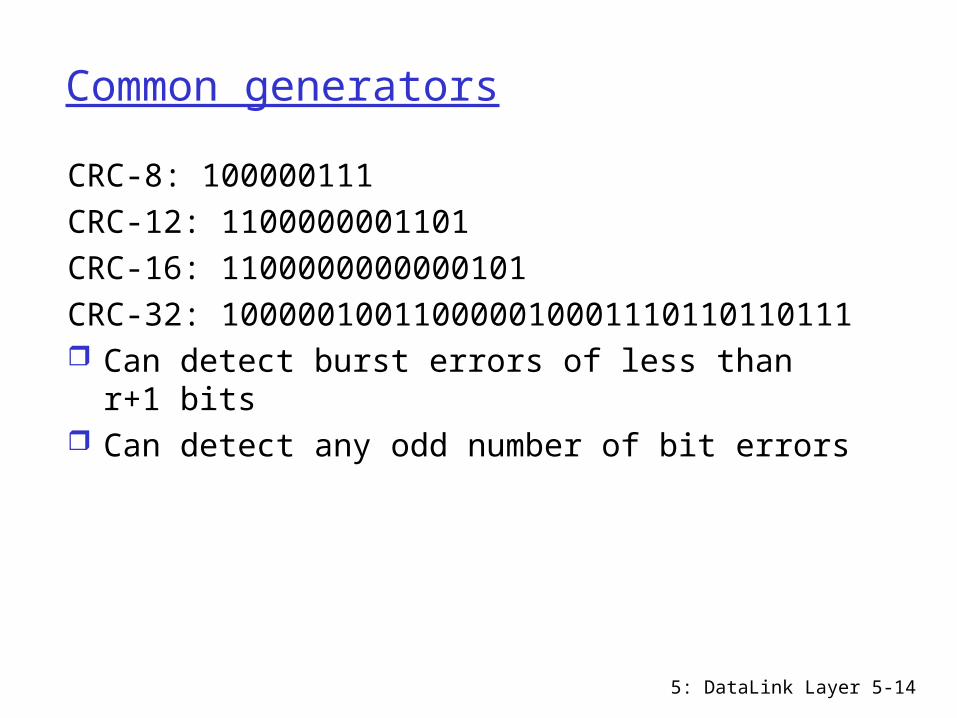
Common generators
CRC-8: 100000111CRC-12: 1100000001101CRC-16: 1100000000000101CRC-32:
100000100110000010001110110110111 Can detect burst errors of less than r+1 bits Can detect any odd number of bit errors

5: DataLink Layer 5-15
Chapter 5 outline
5.1 Introduction and services
5.2 Error detection and correction
5.3Multiple access protocols
5.4 LAN addresses and ARP
5.5 Ethernet
5.6 Hubs, bridges, and switches
5.7 Wireless links and LANs
5.8 PPP 5.9 ATM 5.10 Frame Relay
5: DataLink Layer 5-16
Multiple Access Links
Two types of “links”: point-to-point
single sender, single receiver link between two routers, or between a dial-up
modem and an ISP router
broadcast (shared wire or medium) multiple sending and receiving nodes connected to
single shared channel Ethernet, 802.11 wireless LAN
5: DataLink Layer 5-17
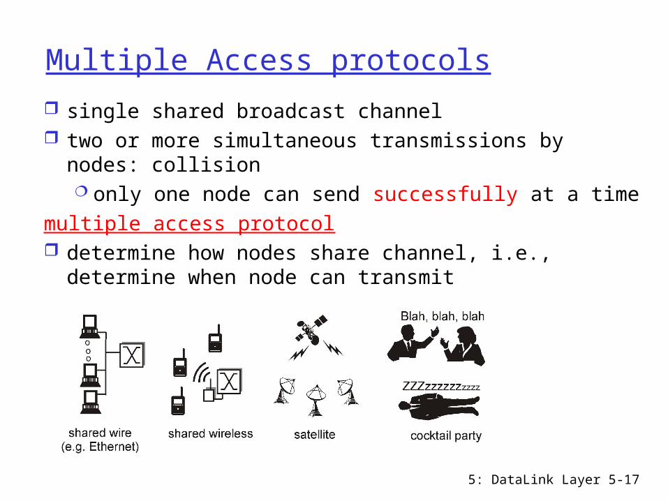
Multiple Access protocols
single shared broadcast channel two or more simultaneous transmissions by nodes:
collision only one node can send successfully at a time
multiple access protocol determine how nodes share channel, i.e.,
determine when node can transmit
5: DataLink Layer 5-18
Ideal Multiple Access Protocol
Broadcast channel of rate R bps1. When only one node wants to transmit, it can
send at rate R.2. When M nodes want to transmit, each can
send at average rate R/M3. Fully decentralized: no special node to
coordinate transmissions4. Simple
5: DataLink Layer 5-19
Multiple Access Protocols: a taxonomy
Three broad classes: Channel Partitioning Protocols
divide channel into smaller “pieces” (time slots, frequency, code)
allocate piece to node for exclusive use
Random Access Protocols channel not divided, allow collisions “recover” from collisions
Taking-turns Protocols tightly coordinate shared access to avoid collisions

5: DataLink Layer 5-20
Channel Partitioning: TDMA
TDMA: time division multiple access divide time into time frames and divide each
time frame into fixed length time slots (length = pkt trans time)
each station gets one slot in each frame unused slots go idle example: 6-station LAN, 1,3,4 have pkt, slots
2,5,6 idle
5: DataLink Layer 5-21
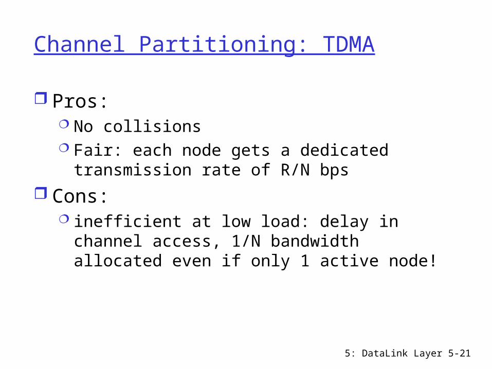
Channel Partitioning: TDMA
Pros: No collisions Fair: each node gets a dedicated
transmission rate of R/N bps Cons:
inefficient at low load: delay in channel access, 1/N bandwidth allocated even if only 1 active node!
5: DataLink Layer 5-22
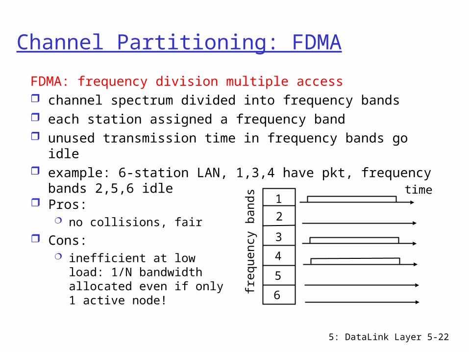
Channel Partitioning: FDMA
FDMA: frequency division multiple access channel spectrum divided into frequency bands each station assigned a frequency band unused transmission time in frequency bands go idle example: 6-station LAN, 1,3,4 have pkt, frequency bands
2,5,6 idle
frequ
ency
bands time
1
2
3
4
5
6
Pros: no collisions, fair
Cons: inefficient at low load: 1/N
bandwidth allocated even if only 1 active node!

5: DataLink Layer 5-23
Channel Partitioning: CDMA
CDMA: Code Division Multiple Access used mostly in wireless broadcast channels
(cellular, satellite, etc) all users share same frequency, but each user
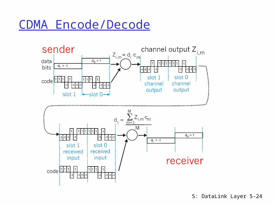
assigned unique code to encode data encoded signal = original bit X M-bit code decoding:
original bit = normalized inner-product of encoded signal S and code C
i.e., original bit =
M
iiiCSM 1
1
5: DataLink Layer 5-24
CDMA Encode/Decode
5: DataLink Layer 5-25
CDMA: two-sender interference
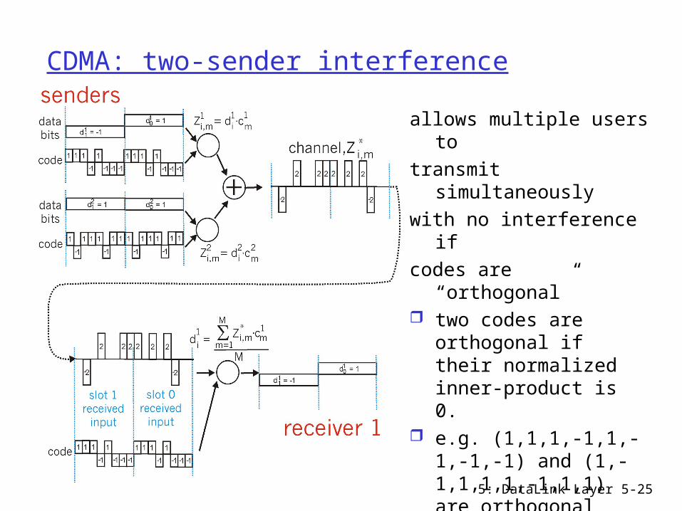
allows multiple users to transmit simultaneously with no interference if codes are “orthogonal” two codes are
orthogonal if their normalized inner-product is 0.
e.g. (1,1,1,-1,1,-1,-1,-1) and (1,-1,1,1,1,-1,1,1) are orthogonal

5: DataLink Layer 5-26
Random Access Protocols
When node has packet to send transmit at full channel data rate R. no a priori coordination among nodes
two or more transmitting nodes -> “collision”, random access protocol specifies:
how to recover from collisions (e.g., via delayed retransmissions)
Examples of random access protocols: slotted ALOHA ALOHA CSMA, CSMA/CD, CSMA/CA
5: DataLink Layer 5-27
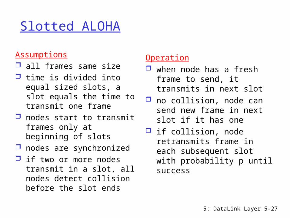
Slotted ALOHA
Assumptions all frames same size time is divided into equal
sized slots, a slot equals the time to transmit one frame
nodes start to transmit frames only at beginning of slots
nodes are synchronized if two or more nodes
transmit in a slot, all nodes detect collision before the slot ends
Operation when node has a fresh frame
to send, it transmits in next slot
no collision, node can send new frame in next slot if it has one
if collision, node retransmits frame in each subsequent slot with probability p until success

5: DataLink Layer 5-28
Slotted ALOHA
Pros single active node can continuously transmit at full rate
of channel highly decentralized: each node independently decides
when to retransmit, only slots in nodes need to be in sync
SimpleCons collisions waste slots idle slots
C = collision slot, E = empty slot, S = successful slot

5: DataLink Layer 5-29
Slotted Aloha efficiency
Suppose N nodes with many frames to send, each transmits in slot with probability p
prob that a given node has success in a slot = p(1-p)N-1
prob that any node has a success = Np(1-p)N-1
For max efficiency with N nodes, find p* (=1/N) that maximizes Np(1-p)N-
1
For many nodes, take limit of Np*(1-p*)N-1 as N goes to infinity, gives 1/e = .37
Efficiency is the long-run fraction of successful slots when there are many nodes, each with many frames to send
At best: channelused for useful transmissions 37%of time!

5: DataLink Layer 5-30
Pure (unslotted) ALOHA
unslotted Aloha: simpler, no synchronization when frame first arrives: transmit immediately If collision, retransmit with prob. P, or wait for a frame
transmission time with prob. 1-p collision probability increases:
frame sent at t0 collides with other frames sent in [t0-1,t0+1]

5: DataLink Layer 5-31
Pure Aloha efficiency
P(success by given node) = P(node transmits) .
P(no other node transmits in [t0-1,t0] .
P(no other node transmits in [t0,t0 +1]
= p . (1-p)N-1 . (1-p)N-1
= p . (1-p)2(N-1)
… choosing optimum p and then letting n -> infty ...
= 1/(2e) = .18
Even worse ! Price paid for a fully decentralized protocol.
5: DataLink Layer 5-32
CSMA (Carrier Sense Multiple Access)
CSMA: listen before transmit: If channel sensed idle: transmit entire frame If channel sensed busy, wait a random amount of
time and sense the channel again
Human analogy: don’t interrupt others!
5: DataLink Layer 5-33
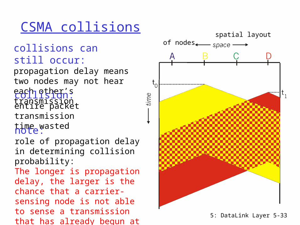
CSMA collisions
collisions can still occur:propagation delay means two nodes may not heareach other’s transmissioncollision:entire packet transmission time wasted
spatial layout of nodes
note:role of propagation delay in determining collision probability:The longer is propagation delay, the larger is the chance that a carrier-sensing node is not able to sense a transmission that has already begun at another node

5: DataLink Layer 5-34
CSMA/CD (Collision Detection)CSMA/CD: carrier sensing, deferral as in CSMA
Listen to channel while transmitting If collision detected, stop transmitting, reducing channel
wastage

5: DataLink Layer 5-35
“Taking Turns” protocols
channel partitioning protocols: share channel efficiently and fairly at high
load inefficient at low load: 1/N bandwidth
allocated even if only 1 active node Random access protocols
efficient at low load: single node can fully utilize channel
high load: collision overhead“taking turns” protocols
look for best of both worlds!

5: DataLink Layer 5-36
“Taking Turns” protocols
Polling: master node
“invites” each node to transmit in turn
concerns: polling delay single point of failure
(master node)
Token passing: decentralized: no master node token passed from one node
to next sequentially. when receive a token:
send up to a maximum number of frames if has frames to send
forward token to next node
concerns: latency single point of failure
(token)
5: DataLink Layer 5-37
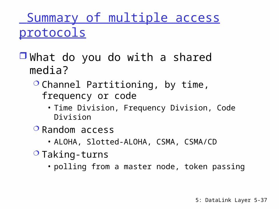
Summary of multiple access protocols
What do you do with a shared media? Channel Partitioning, by time, frequency or
code• Time Division, Frequency Division, Code Division
Random access• ALOHA, Slotted-ALOHA, CSMA, CSMA/CD
Taking-turns• polling from a master node, token passing

5: DataLink Layer 5-38
LAN technologies
addressing Ethernet hubs, bridges, switches 802.11
5: DataLink Layer 5-39
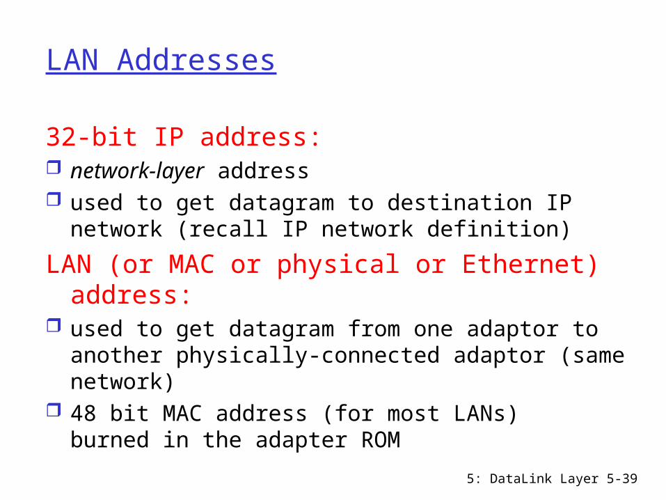
LAN Addresses
32-bit IP address: network-layer address used to get datagram to destination IP network
(recall IP network definition)
LAN (or MAC or physical or Ethernet) address:
used to get datagram from one adaptor to another physically-connected adaptor (same network)
48 bit MAC address (for most LANs) burned in the adapter ROM
5: DataLink Layer 5-40
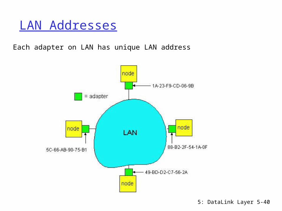
LAN Addresses
Each adapter on LAN has unique LAN address

5: DataLink Layer 5-41
LAN Address (more)
MAC address allocation administered by IEEE manufacturer buys portion of MAC address
space (to assure uniqueness) MAC flat address => portability
does not change no matter where the adaptor goes
IP hierarchical address NOT portable depends on IP network to which node is attached
Analogy: (a) MAC address: like Social Security
Number (b) IP address: like postal address
5: DataLink Layer 5-42
Recall earlier routing discussion
223.1.1.1
223.1.1.2
223.1.1.3
223.1.1.4 223.1.2.9
223.1.2.2
223.1.2.1
223.1.3.2223.1.3.1
223.1.3.27
A
BE
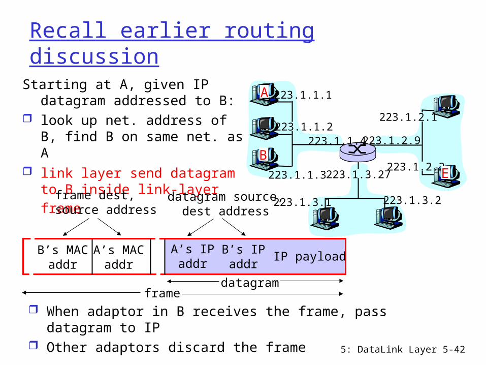
Starting at A, given IP datagram addressed to B:
look up net. address of B, find B on same net. as A
link layer send datagram to B inside link-layer frame
B’s MACaddr
A’s MACaddr
A’s IPaddr
B’s IPaddr
IP payload
datagramframe
frame dest,source address
datagram source,dest address
When adaptor in B receives the frame, pass datagram to IP
Other adaptors discard the frame
5: DataLink Layer 5-43
ARP: Address Resolution Protocol (RFC826)
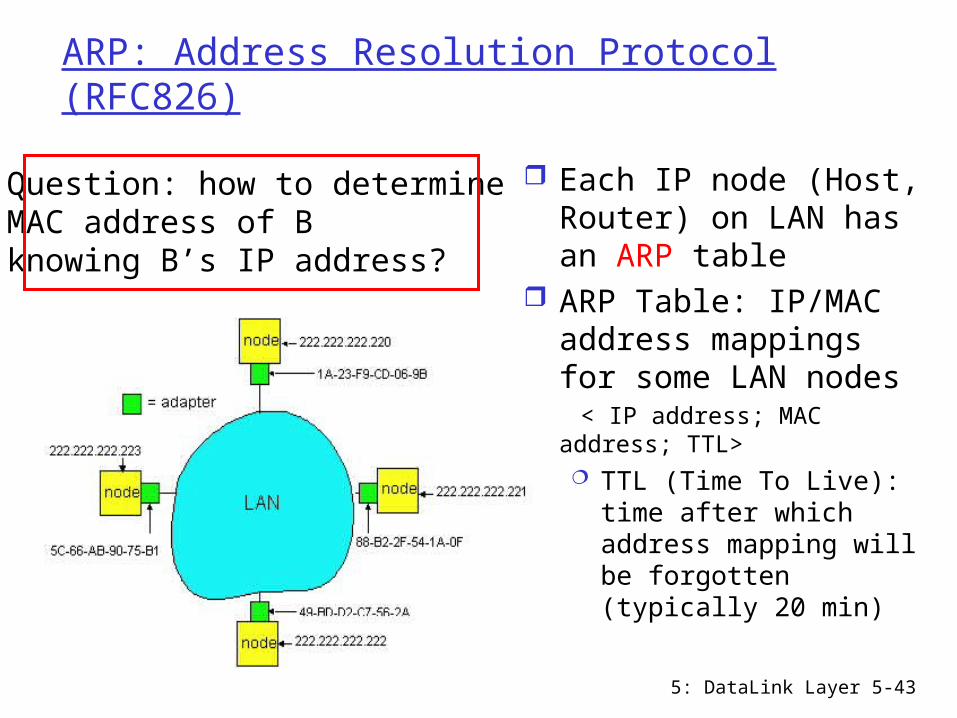
Each IP node (Host, Router) on LAN has an ARP table
ARP Table: IP/MAC address mappings for some LAN nodes
< IP address; MAC address; TTL> TTL (Time To Live):
time after which address mapping will be forgotten (typically 20 min)
Question: how to determineMAC address of Bknowing B’s IP address?
5: DataLink Layer 5-44
ARP protocol A wants to send a datagram to B on the same LAN Suppose B’s MAC address is not in A’s ARP table A broadcasts (using broadcast address FF-FF-FF-FF-FF-FF)
an ARP request packet, containing A’s IP address, A’s MAC address and B's IP address
All adaptors on LAN receive ARP request Every node: if A’s IP-to-MAC mapping is in table, update table B: replies to A (unicast) with its MAC address, also adds A
into its ARP table if it’s not there A receives the ARP reply, adds B's IP and MAC addresses
to its ARP table. Soft state: IP-to-MAC address pair in ARP table times out
(goes away) unless refreshed ARP is “plug-and-play”: nodes create their ARP tables
without intervention from network administrator ARP resolves IP addresses only for nodes on the same
LAN

5: DataLink Layer 5-45
Routing to another LAN
walkthrough: send datagram from A to B via R assume A knows B’s IP address
Two ARP tables in router R, one for each IP network (LAN)
A
RB

5: DataLink Layer 5-46
A creates datagram with source A, destination B A uses ARP to get R’s MAC address for 111.111.111.110 A creates link-layer frame with R's MAC address as dest,
frame contains A-to-B IP datagram A’s data link layer sends frame R’s data link layer receives frame R removes IP datagram from Ethernet frame, sees it’s
destined to B R uses ARP to get B’s MAC address R creates frame containing A-to-B IP datagram, sends to
B
A
R B

5: DataLink Layer 5-47
Ethernet (IEEE 802.3)
“dominant” LAN technology: first widely deployed LAN technology simpler, cheaper than token ring, FDDI, and
ATM Lesson learned: KISS (Keep It Simple, Stupid)
kept up with speed race: 10, 100, 1000 Mbps
Metcalfe’s Ethernetsketch

5: DataLink Layer 5-48
Ethernet Frame Structure
Sending adapter encapsulates IP datagram (or other network layer protocol packet) in Ethernet frame
Preamble: 7 bytes with pattern 10101010 followed by one
byte with pattern 10101011 used to synchronize receiver, sender clock rates
5: DataLink Layer 5-49
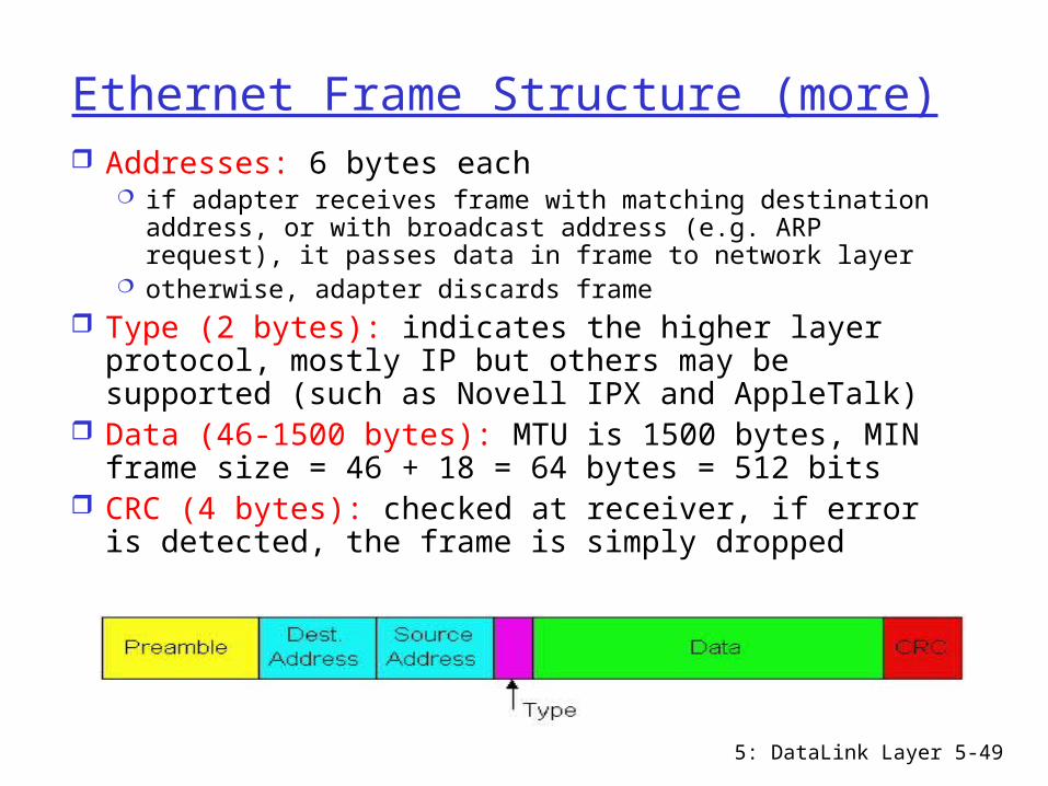
Ethernet Frame Structure (more) Addresses: 6 bytes each
if adapter receives frame with matching destination address, or with broadcast address (e.g. ARP request), it passes data in frame to network layer
otherwise, adapter discards frame Type (2 bytes): indicates the higher layer
protocol, mostly IP but others may be supported (such as Novell IPX and AppleTalk)
Data (46-1500 bytes): MTU is 1500 bytes, MIN frame size = 46 + 18 = 64 bytes = 512 bits
CRC (4 bytes): checked at receiver, if error is detected, the frame is simply dropped
5: DataLink Layer 5-50
Unreliable, connectionless service
Connectionless: No handshaking between sending and receiving adapter.
Unreliable: receiving adapter doesn’t send ACKs or NAKs to sending adapter stream of datagrams passed to network layer can
have gaps gaps will be filled if app is using TCP otherwise, app will see the gaps

5: DataLink Layer 5-51
Ethernet uses CSMA/CD
No slots adapter doesn’t
transmit if it senses that some other adapter is transmitting, that is, carrier sense
transmitting adapter aborts when it senses that another adapter is transmitting, that is, collision detection
Before attempting a retransmission, adapter waits a random time
5: DataLink Layer 5-52
Ethernet CSMA/CD algorithm
1. Adaptor gets datagram from network layer and creates frame
2. If adapter senses channel idle, it starts to transmit frame. If it senses channel busy, waits until channel idle (plus 96 bit times) and then transmits
3. If adapter transmits entire frame without detecting another transmission, the adapter is done with frame!
4. If adapter detects another transmission while transmitting, aborts and sends a 48-bit jam signal
5. After aborting, adapter enters exponential backoff: after the mth collision, adapter chooses a K at random from {0,1,2,…,2m-1} where m = min(m,10). Adapter waits K*512 bit times and returns to Step 2

5: DataLink Layer 5-53
Ethernet’s CSMA/CD (more)
Jam Signal: make sure all other transmitters are aware of collision
Bit time: 0.1 microsec for 10 Mbps Ethernet;for K=1023, wait time is about 50 msec
Exponential Backoff: Goal: adapt
retransmission attempts to estimated current load heavy load: random wait
will be longer first collision: choose K
from {0,1}; delay is K x 512 bit transmission times
after second collision: choose K from {0,1,2,3}…
after ten or more collisions, choose K from {0,1,2,3,4,…,1023}

5: DataLink Layer 5-54
Why 64 bytes min frame length? 10Base5 Ethernet: 10Mbps, max segment 500m, max 4
repeaters, max network diameter 2500m Repeater: physical layer device that amplifies and retransmits
bits it hears on one interface to its other interfaces, used to connect multiple segments
Round trip time (worst case collision detection time) about 50 microsec All frames must take more than 50 microsec to send so that
transmission is still taking place when the noise burst gets back to sender
With 10Mbps bandwidth, 1 bit time = 0.1 microsec minimum frame size at least 500 bits, choose 512 bits to
add some margin of safety As network speed goes up, the minimum frame length
must go up or the maximum cable length must come down E.g. for a 2500m 1Gbps LAN, minimum frame size should be
6400 bytes
5: DataLink Layer 5-55
CSMA/CD efficiency
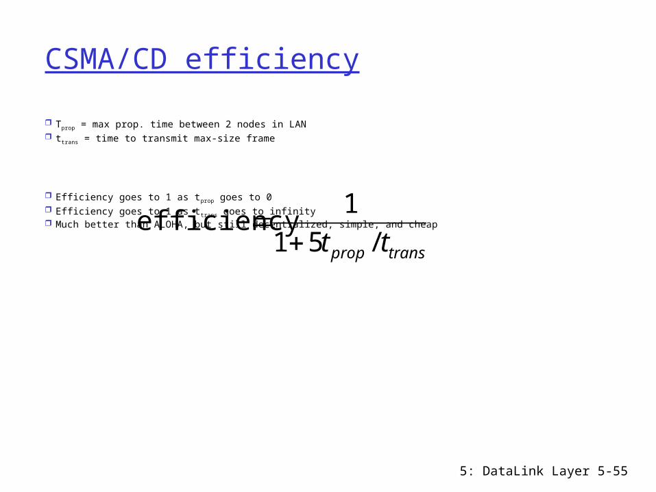
Tprop = max prop. time between 2 nodes in LAN ttrans = time to transmit max-size frame
Efficiency goes to 1 as tprop goes to 0 Efficiency goes to 1 as ttrans goes to infinity Much better than ALOHA, but still decentralized, simple, and cheap
transprop tt /51
1efficiency
5: DataLink Layer 5-56
Ethernet Technologies: 10Base2
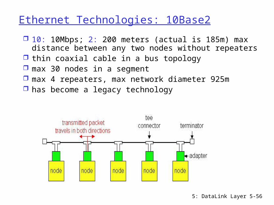
10: 10Mbps; 2: 200 meters (actual is 185m) max distance between any two nodes without repeaters
thin coaxial cable in a bus topology max 30 nodes in a segment max 4 repeaters, max network diameter 925m has become a legacy technology
5: DataLink Layer 5-57
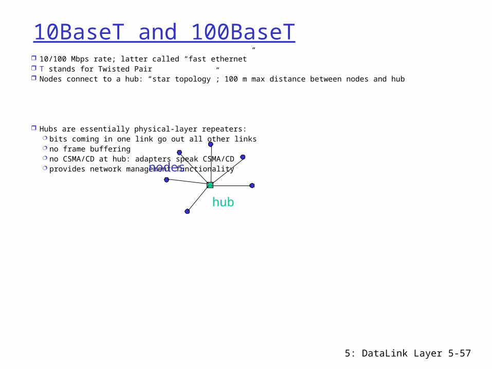
10BaseT and 100BaseT 10/100 Mbps rate; latter called “fast ethernet” T stands for Twisted Pair Nodes connect to a hub: “star topology”; 100 m max distance between nodes and hub
Hubs are essentially physical-layer repeaters: bits coming in one link go out all other links no frame buffering no CSMA/CD at hub: adapters speak CSMA/CD provides network management functionality
hub
nodes

5: DataLink Layer 5-58
Gigabit Ethernet (IEEE 802.3z)
1Gbps data rate use standard Ethernet frame format star topology, allows for point-to-point
links (use switches) and shared broadcast channels (use hubs)Full-Duplex at 1 Gbps for point-to-
point links in shared mode, CSMA/CD is used

5: DataLink Layer 5-59
Chapter 5 outline
5.1 Introduction and services
5.2 Error detection and correction
5.3Multiple access protocols
5.4 LAN addresses and ARP
5.5 Ethernet
5.6 Hubs, bridges, and switches
5.7 Wireless links and LANs
5.8 PPP 5.9 ATM 5.10 Frame Relay

5: DataLink Layer 5-60
Interconnecting LAN segments
Hubs Bridges Switches
Remark: switches are essentially high performance multi-interface bridges.
What we say about bridges also holds for switches!

5: DataLink Layer 5-61
Interconnecting with hubs Hubs are physical layer devices: operate on bits Backbone hub interconnects LAN segments Extends max distance between nodes But individual segment collision domains become
one large collision domain if a node in CS and a node in EE transmit at same time:
collision Can’t interconnect 10BaseT & 100BaseT

5: DataLink Layer 5-62
Bridges
Link layer device: operate on frames stores and forwards Ethernet frames examines frame header and forwards frame
based on destination MAC address when frame is to be forwarded on a segment,
uses CSMA/CD to access the segment can interconnect different LAN technologies
plug-and-play, self-learning bridges do not need to be configured

5: DataLink Layer 5-63
Bridges: traffic isolation
Bridge installation breaks LAN into LAN segments bridges filter packets:
same-LAN-segment frames not usually forwarded onto other LAN segments
segments become separate collision domains
bridge collision domain
collision domain
= hub
= host
LAN
LAN segment LAN segment
5: DataLink Layer 5-64
Forwarding
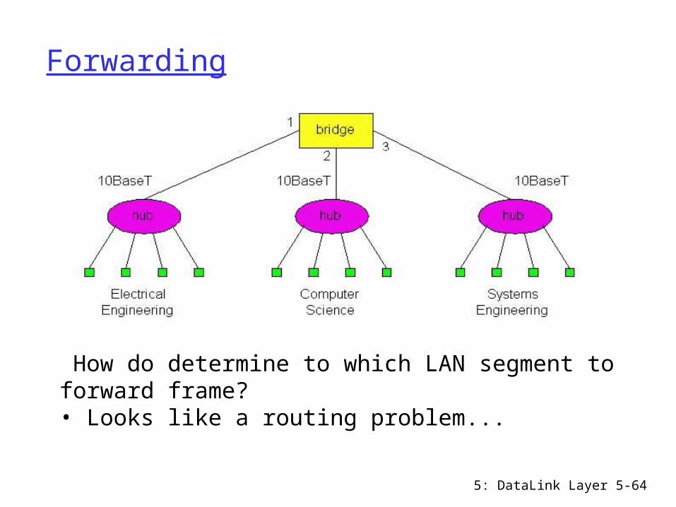
How do determine to which LAN segment to forward frame?• Looks like a routing problem...

5: DataLink Layer 5-65
Self learning
A bridge has a bridge table entry in bridge table:
(Node LAN Address, Bridge Interface, Time Stamp) stale entries in table dropped (TTL typically 60 min)
bridges learn which hosts can be reached through which interfaces bridge table initially empty when frame received, bridge “learns” location of sender records sender’s LAN address, arriving interface, and
current time in bridge table delete an address in table if no frames are received with
that address as the source address after some period of time
5: DataLink Layer 5-66
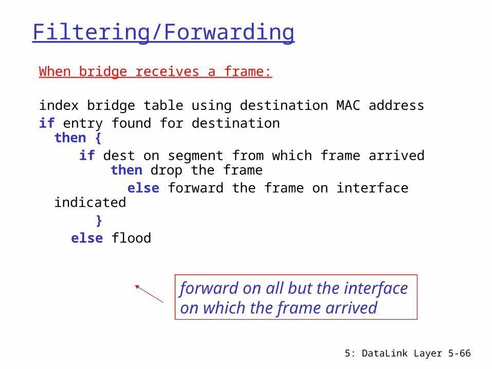
Filtering/Forwarding
When bridge receives a frame:
index bridge table using destination MAC addressif entry found for destination
then { if dest on segment from which frame arrived
then drop the frame else forward the frame on interface indicated } else flood
forward on all but the interface on which the frame arrived

5: DataLink Layer 5-67
Bridge example
Suppose C sends a frame to D and D replies back with a frame to C.
Bridge receives frame from C notes in bridge table that C is on interface 1 because D is not in table, bridge sends frame into
interfaces 2 and 3
frame received by D
5: DataLink Layer 5-68
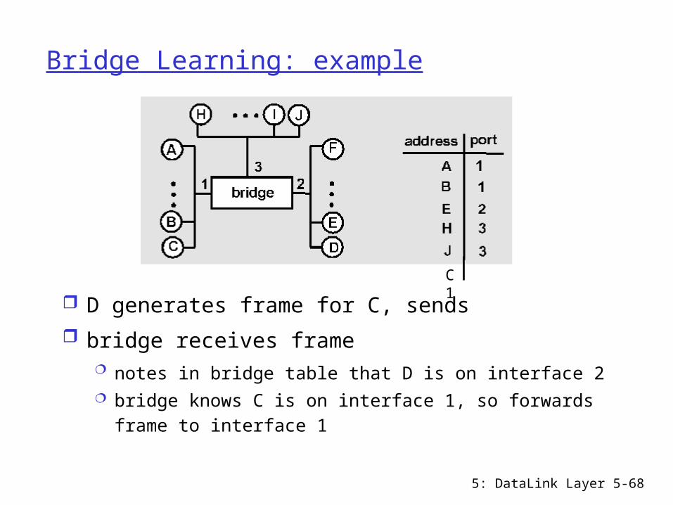
Bridge Learning: example
D generates frame for C, sends bridge receives frame
notes in bridge table that D is on interface 2 bridge knows C is on interface 1, so forwards frame
to interface 1
C 1

5: DataLink Layer 5-69
Spanning Tree
for increased reliability, desirable to have redundant, alternative paths from source to dest
with multiple paths, cycles result - bridges may multiply and forward frame forever
solution: bridges determine a spanning tree by disabling subset of interfaces
Disabled
5: DataLink Layer 5-70
Some bridge features
isolates collision domains resulting in higher total max throughput
limitless number of nodes and geographical coverage
can connect different Ethernet types transparent (“plug-and-play”): no configuration
necessary
5: DataLink Layer 5-71
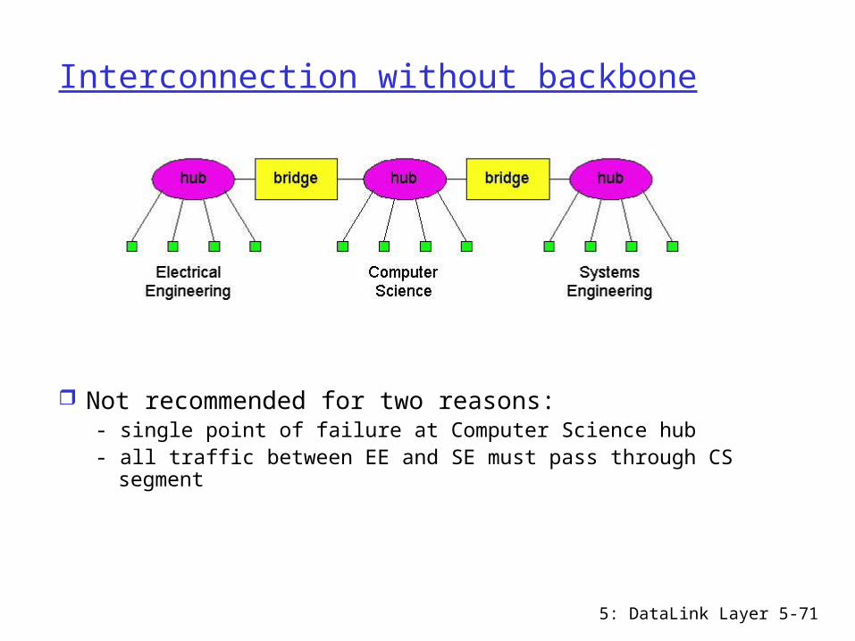
Interconnection without backbone
Not recommended for two reasons:- single point of failure at Computer Science hub- all traffic between EE and SE must pass through CS
segment

5: DataLink Layer 5-72
Backbone configuration
Recommended !With a backbone, each pair of LAN segments can communicate without passing through a third-party LAN segment
5: DataLink Layer 5-73
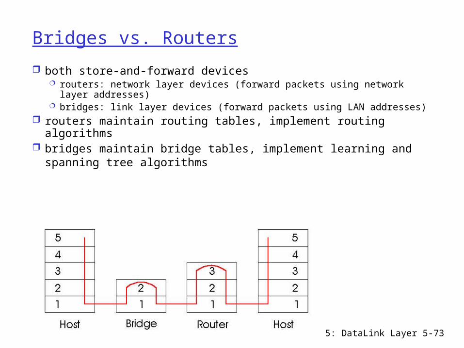
Bridges vs. Routers
both store-and-forward devices routers: network layer devices (forward packets using network layer
addresses) bridges: link layer devices (forward packets using LAN addresses)
routers maintain routing tables, implement routing algorithms
bridges maintain bridge tables, implement learning and spanning tree algorithms
5: DataLink Layer 5-74
Routers vs. Bridges
Bridges + and - + Bridges are plug-and-play+ Bridge operation is simpler requiring less
packet processinghigh packet filtering and forwarding rates
- All traffic confined to spanning tree, even when alternative paths are available
- Bridges do not offer protection from broadcast storms

5: DataLink Layer 5-75
Routers vs. Bridges
Routers + and -+ arbitrary topologies can be supported, cycling is
limited by TTL counters (and good routing protocols)packets can use the best path
+ provide protection against broadcast storms- require IP address configuration (not plug and
play)- require larger packet processing time
bridges do well in small (few hundred hosts) networks while routers used in large (thousands of hosts) networks

5: DataLink Layer 5-76
Ethernet Switches
Essentially high-performance multi-interface bridges switches have large number of
interfaces layer 2 (frame) forwarding,
filtering using LAN addresses automatically build forwarding
tables often: individual hosts star-
connected into switch Switching: A-to-A’, B-to-B’, and
C-to-C’ simultaneously Full duplex, no collisions!
combinations of 10/100/1000 Mbps interfaces
5: DataLink Layer 5-77
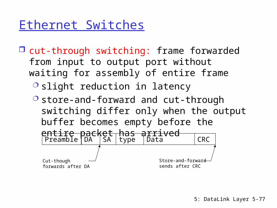
Ethernet Switches
cut-through switching: frame forwarded from input to output port without waiting for assembly of entire frame slight reduction in latency store-and-forward and cut-through
switching differ only when the output buffer becomes empty before the entire packet has arrivedPreamble DA SA type Data CRC
Cut-though forwards after DA
Store-and-forward sends after CRC
5: DataLink Layer 5-78
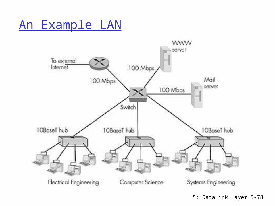
An Example LAN
Dedicated
Shared
5: DataLink Layer 5-79
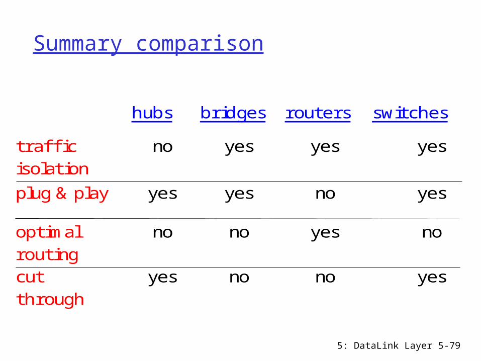
Summary comparison
hubs bridges routers switches
traffi cisolation
no yes yes yes
plug & play yes yes no yes
optimalrouting
no no yes no
cutthrough
yes no no yes
5: DataLink Layer 5-80
Chapter 5 outline
5.1 Introduction and services
5.2 Error detection and correction
5.3Multiple access protocols
5.4 LAN addresses and ARP
5.5 Ethernet
5.6 Hubs, bridges, and switches
5.7 Wireless links and LANs
5.8 PPP 5.9 ATM 5.10 Frame Relay
5: DataLink Layer 5-81
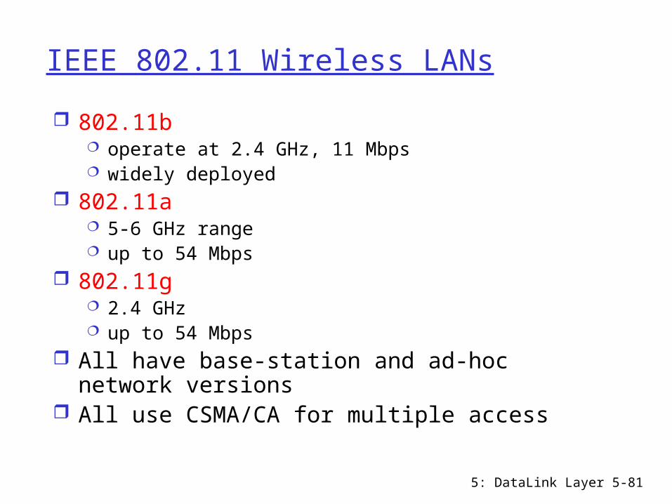
IEEE 802.11 Wireless LANs
802.11b operate at 2.4 GHz, 11 Mbps widely deployed
802.11a 5-6 GHz range up to 54 Mbps
802.11g 2.4 GHz up to 54 Mbps
All have base-station and ad-hoc network versions
All use CSMA/CA for multiple access
5: DataLink Layer 5-82
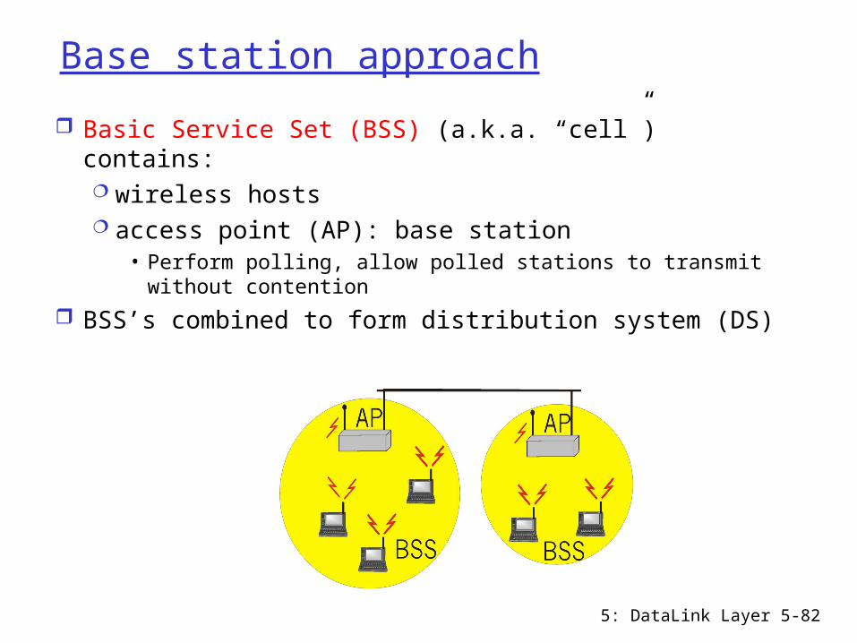
Base station approach
Basic Service Set (BSS) (a.k.a. “cell”) contains: wireless hosts access point (AP): base station
• Perform polling, allow polled stations to transmit without contention
BSS’s combined to form distribution system (DS)

5: DataLink Layer 5-83
Ad Hoc Network approach
No AP No connection to the outside world Wireless hosts communicate with each
other Applications:
“laptop” meeting in conference room, car

5: DataLink Layer 5-84
IEEE 802.11: multiple access
Collision if 2 or more nodes transmit at same time
CSMA makes sense: shouldn’t cause a collision if you sense another
transmission get all the bandwidth if you’re the only one transmitting
Collision detection doesn’t work: hidden terminal problem and fading problem
location
signal stre
ngth

5: DataLink Layer 5-85
IEEE 802.11 MAC Protocol: CSMA/CA802.11 CSMA: sender- if sense channel idle for DIFS sec. then transmit entire frame,
duration field of frame indicates how long the medium will be busy
-if sense channel busy then wait until channel becomes idle for a DIFS period, then computes a random backoff time and counts down the time as the channel is sensed idle
802.11 CSMA receiver- if received OK return ACK after SIFS sec.Other stations: adjust NAV (network
allocation vector) based on the duration field

5: DataLink Layer 5-86
Collision avoidance mechanisms
Problem: two nodes, hidden from each other, transmit
complete frames even though collision has occurred
wasted bandwidth for long duration! Solution:
use small reservation packets nodes track reservation interval with NAV
5: DataLink Layer 5-87
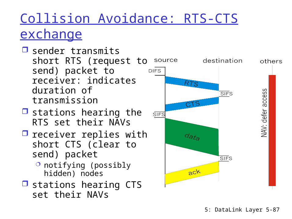
Collision Avoidance: RTS-CTS exchange sender transmits short
RTS (request to send) packet to receiver: indicates duration of transmission
stations hearing the RTS set their NAVs
receiver replies with short CTS (clear to send) packet notifying (possibly
hidden) nodes stations hearing CTS
set their NAVs
5: DataLink Layer 5-88
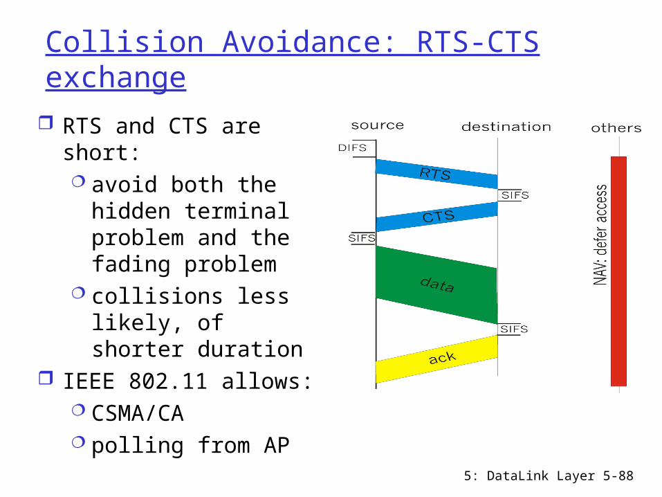
Collision Avoidance: RTS-CTS exchange
RTS and CTS are short: avoid both the
hidden terminal problem and the fading problem
collisions less likely, of shorter duration
IEEE 802.11 allows: CSMA/CA polling from AP
5: DataLink Layer 5-89
Chapter 5 outline
5.1 Introduction and services
5.2 Error detection and correction
5.3Multiple access protocols
5.4 LAN addresses and ARP
5.5 Ethernet
5.6 Hubs, bridges, and switches
5.7 Wireless links and LANs
5.8 PPP 5.9 ATM 5.10 Frame Relay
5: DataLink Layer 5-90
Point to Point Data Link Control
one sender, one receiver, one link: easier than broadcast link no Media Access Control no need for explicit MAC addressing e.g., dialup link, link between two routers
popular point-to-point data link protocols: PPP (point-to-point protocol) HDLC: High level data link control
5: DataLink Layer 5-91
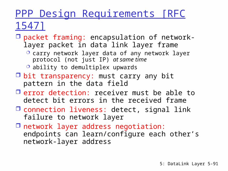
PPP Design Requirements [RFC 1547] packet framing: encapsulation of network-layer
packet in data link layer frame carry network layer data of any network layer protocol
(not just IP) at same time ability to demultiplex upwards
bit transparency: must carry any bit pattern in the data field
error detection: receiver must be able to detect bit errors in the received frame
connection liveness: detect, signal link failure to network layer
network layer address negotiation: endpoints can learn/configure each other’s network-layer address
5: DataLink Layer 5-92
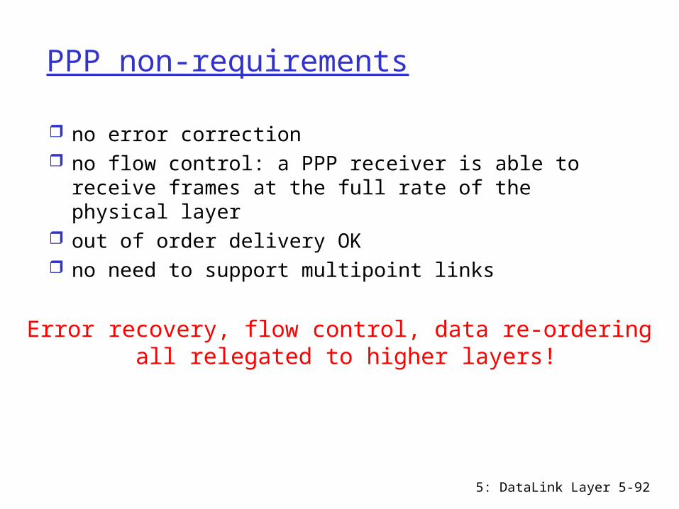
PPP non-requirements
no error correction no flow control: a PPP receiver is able to receive
frames at the full rate of the physical layer out of order delivery OK no need to support multipoint links
Error recovery, flow control, data re-ordering all relegated to higher layers!
5: DataLink Layer 5-93
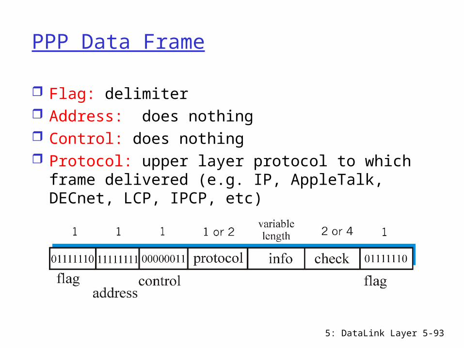
PPP Data Frame
Flag: delimiter Address: does nothing Control: does nothing Protocol: upper layer protocol to which frame
delivered (e.g. IP, AppleTalk, DECnet, LCP, IPCP, etc)

5: DataLink Layer 5-94
PPP Data Frame
info: upper layer data being carried, default maximum is 1500 bytes
check: cyclic redundancy check for error detection

5: DataLink Layer 5-95
Byte Stuffing
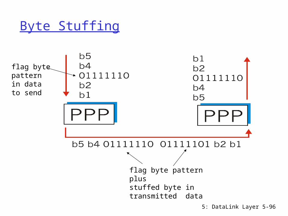
“data transparency” requirement: data field must be allowed to include flag pattern <01111110> Q: is received <01111110> data or flag?
Sender: adds (“stuffs”) a control escape byte < 01111101> before each < 01111110> data byte
Receiver: 01111110 preceded by 01111101: discard first
byte 01111110 not preceded by 01111101: flag byte
If control escape byte appears in data, it must be preceded by a stuffed control escape byte
5: DataLink Layer 5-96
Byte Stuffing
flag bytepatternin datato send
flag byte pattern plusstuffed byte in transmitted data
5: DataLink Layer 5-97
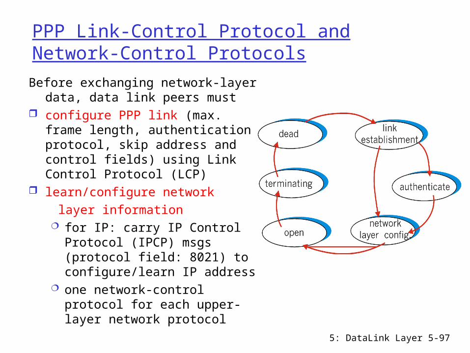
PPP Link-Control Protocol and Network-Control Protocols
Before exchanging network-layer data, data link peers must
configure PPP link (max. frame length, authentication protocol, skip address and control fields) using Link Control Protocol (LCP)
learn/configure network layer information
for IP: carry IP Control Protocol (IPCP) msgs (protocol field: 8021) to configure/learn IP address
one network-control protocol for each upper-layer network protocol

5: DataLink Layer 5-98
Chapter 5 outline
5.1 Introduction and services
5.2 Error detection and correction
5.3Multiple access protocols
5.4 LAN addresses and ARP
5.5 Ethernet
5.6 Hubs, bridges, and switches
5.7 Wireless links and LANs
5.8 PPP 5.9 ATM 5.10 Frame Relay

5: DataLink Layer 5-99
Asynchronous Transfer Mode: ATM
Goal: integrated, end-end transport of voice, video, data meeting QoS requirements of voice, video
(versus Internet best-effort model) packet-switching (fixed length packets, called
“cells”) using virtual circuits high-speed: 155Mbps, 622 Mbps, and higher

5: DataLink Layer 5-100
ATM architecture
ATM adaptation layer (AAL): only at edge of ATM network roughly analogous to Internet transport layer different types of AALs to support different types of
services ATM layer: “network” layer
cell (53-byte packet) switching physical layer: deal with voltages, bit timings, and
framing on the physical medium

5: DataLink Layer 5-101
ATM: network or link layer?Vision: end-to-end
transport: “ATM from desktop to desktop” ATM is a network
technologyReality: used to
connect IP backbone routers “IP over ATM” ATM as link layer,
connecting IP routers
5: DataLink Layer 5-102
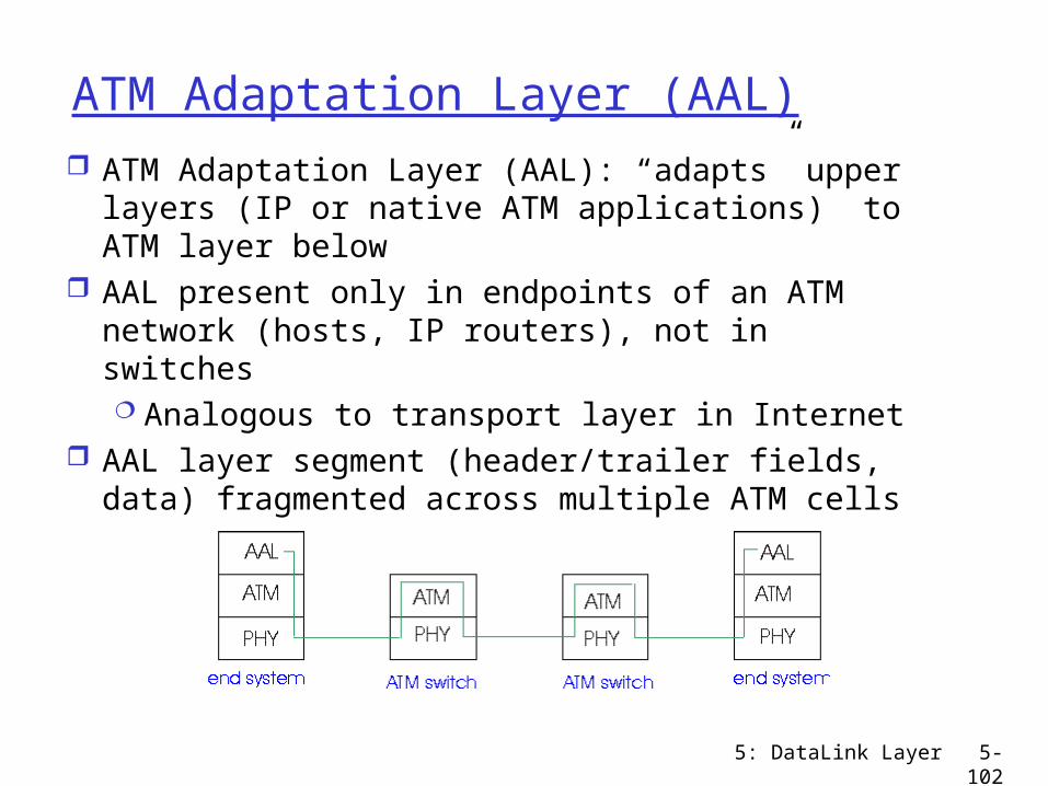
ATM Adaptation Layer (AAL) ATM Adaptation Layer (AAL): “adapts” upper
layers (IP or native ATM applications) to ATM layer below
AAL present only in endpoints of an ATM network (hosts, IP routers), not in switches Analogous to transport layer in Internet
AAL layer segment (header/trailer fields, data) fragmented across multiple ATM cells
5: DataLink Layer 5-103
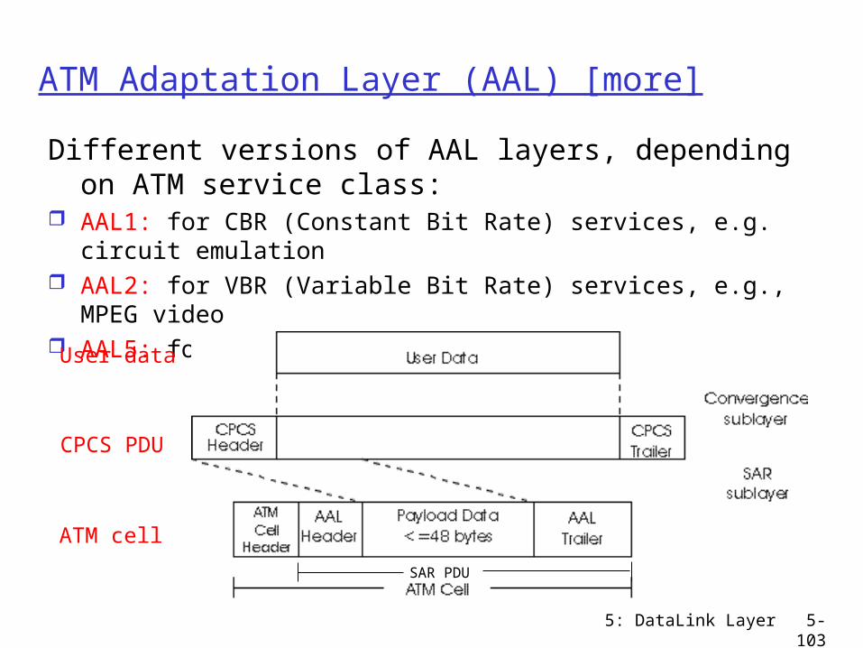
ATM Adaptation Layer (AAL) [more]
Different versions of AAL layers, depending on ATM service class:
AAL1: for CBR (Constant Bit Rate) services, e.g. circuit emulation
AAL2: for VBR (Variable Bit Rate) services, e.g., MPEG video AAL5: for data, e.g, IP datagrams
CPCS PDU
ATM cell
User data
SAR PDU
5: DataLink Layer 5-104
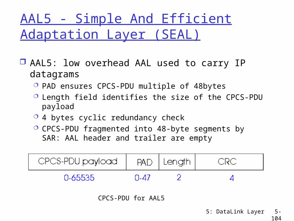
AAL5 - Simple And Efficient Adaptation Layer (SEAL)
AAL5: low overhead AAL used to carry IP datagrams PAD ensures CPCS-PDU multiple of 48bytes Length field identifies the size of the CPCS-PDU
payload 4 bytes cyclic redundancy check CPCS-PDU fragmented into 48-byte segments by SAR:
AAL header and trailer are empty
CPCS-PDU for AAL5

5: DataLink Layer 5-105
ATM LayerService: transport cells across ATM network analogous to IP network layer very different services than IP network layer
NetworkArchitecture
Internet
ATM
ATM
ATM
ATM
ServiceModel
best effort
CBR
VBR
ABR
UBR
Bandwidth
none
constantrateguaranteedrateguaranteed minimumnone
Loss
no
yes
yes
no
no
Order
no
yes
yes
yes
yes
Timing
no
yes
yes
no
no
Congestionfeedback
no (inferredvia loss)nocongestionnocongestionyes
no
Guarantees ?
5: DataLink Layer 5-106
ATM Layer: Virtual Circuits
VC transport: cells carried on VC from source to dest establish virtual circuit before data can flow
• A VC is a path between source and dest, each link of the VC has a virtual circuit identifier (VCI)
each packet carries VC identifier (not destination ID) every switch on source-dest path maintains “state” (in VC
translation table) for each passing connection link, switch resources (bandwidth, buffers) may be
allocated to VC: to get circuit-like performance Permanent VCs (PVCs)
long lasting connections typically: “permanent” route between two IP routers
Switched VCs (SVC): dynamically set up on per-call basis
5: DataLink Layer 5-107
ATM VCs
Advantages of ATM VC approach: QoS performance guarantee for connections
mapped to VC (bandwidth, delay, delay jitter)
Drawbacks of ATM VC approach: one PVC between each source/dest pair
does not scale ( N*(N-1) connections needed )
SVC introduces call setup latency, processing overhead for short lived connections
5: DataLink Layer 5-108
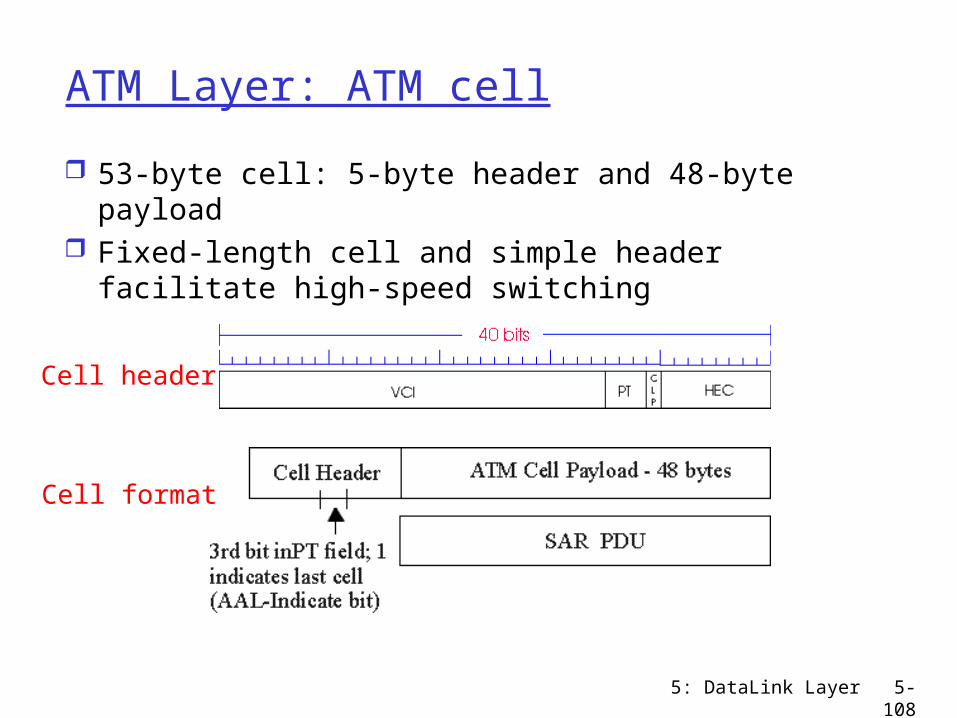
ATM Layer: ATM cell
53-byte cell: 5-byte header and 48-byte payload Fixed-length cell and simple header facilitate
high-speed switching
Cell header
Cell format
5: DataLink Layer 5-109
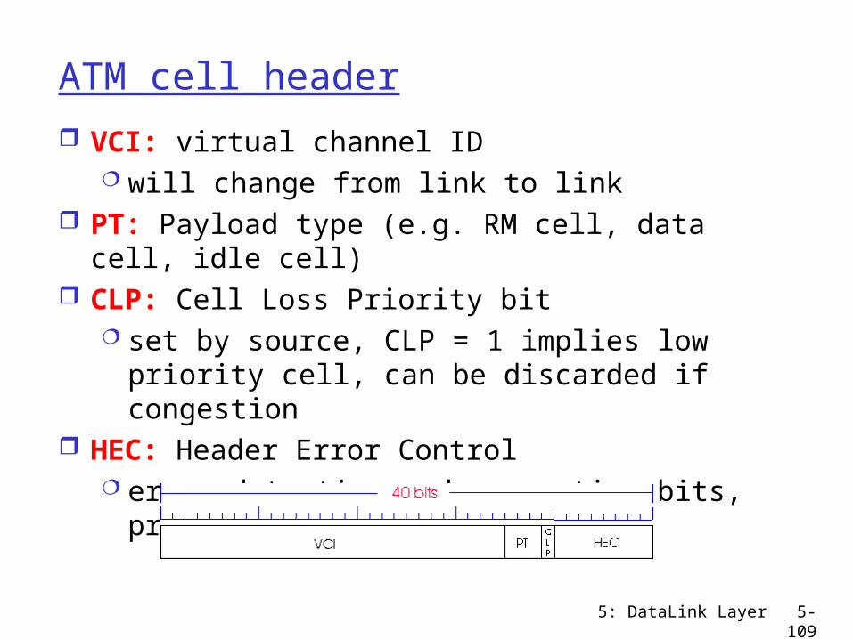
ATM cell header
VCI: virtual channel ID will change from link to link
PT: Payload type (e.g. RM cell, data cell, idle cell)
CLP: Cell Loss Priority bit set by source, CLP = 1 implies low priority
cell, can be discarded if congestion HEC: Header Error Control
error detection and correction bits, protect cell header
5: DataLink Layer 5-110
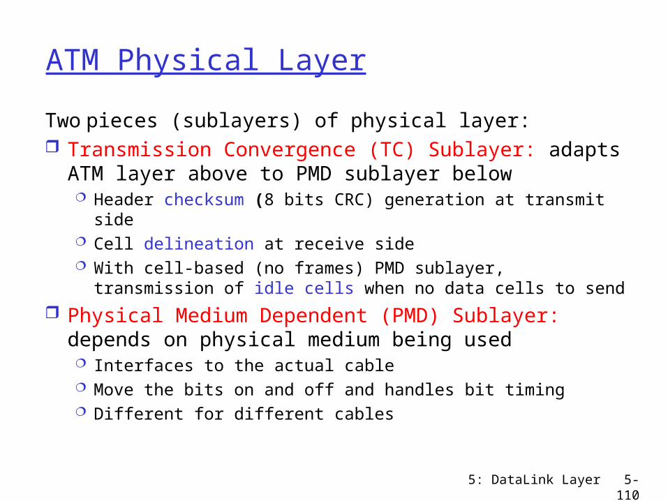
ATM Physical Layer
Two pieces (sublayers) of physical layer: Transmission Convergence (TC) Sublayer: adapts
ATM layer above to PMD sublayer below Header checksum (8 bits CRC) generation at transmit
side Cell delineation at receive side With cell-based (no frames) PMD sublayer, transmission
of idle cells when no data cells to send
Physical Medium Dependent (PMD) Sublayer: depends on physical medium being used Interfaces to the actual cable Move the bits on and off and handles bit timing Different for different cables

5: DataLink Layer 5-111
IP-Over-ATM
Internet-over-ATM protocol stack
Application Layer (HTTP, FTP, etc)
Transport Layer (TCP, UDP)
Network Layer (IP)
AAL5
ATM Layer
ATM Physical Layer
Have a permanent virtual circuit between each pair of routers

5: DataLink Layer 5-112
IP-Over-ATM
IP datagrams encapsulated into ATM AAL5 PDUs
Each router interface that connects to the ATM network has both an IP address and an ATM address
Map from IP address to ATM address: use ARP
5: DataLink Layer 5-113
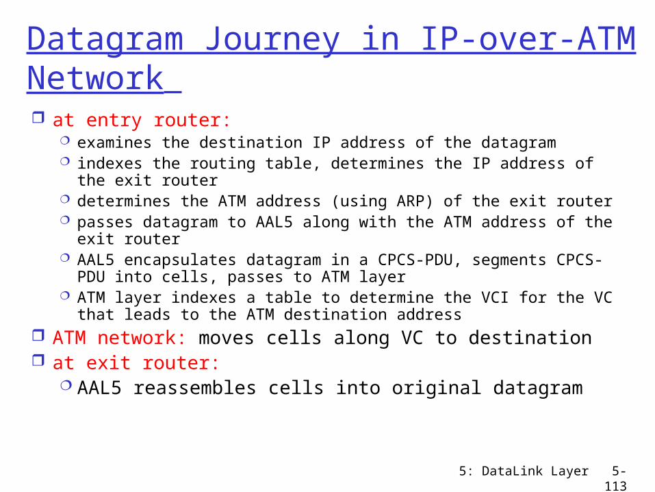
Datagram Journey in IP-over-ATM Network at entry router:
examines the destination IP address of the datagram indexes the routing table, determines the IP address of the exit
router determines the ATM address (using ARP) of the exit router passes datagram to AAL5 along with the ATM address of the
exit router AAL5 encapsulates datagram in a CPCS-PDU, segments CPCS-
PDU into cells, passes to ATM layer ATM layer indexes a table to determine the VCI for the VC that
leads to the ATM destination address ATM network: moves cells along VC to destination at exit router:
AAL5 reassembles cells into original datagram
5: DataLink Layer 5-114
Chapter 5: Summary
data link layer services: error detection/correction sharing a broadcast channel: multiple access link layer addressing, ARP
link layer technologies: Ethernet, hubs, bridges, switches, IEEE 802.11 wireless LANs, PPP, ATM