CHAPTER 5 - NAVIGATIONAL AIDS · SUBJECT: Nautical Chart Manual, Chapter 5-Navigational Aids:...
76
NAUTICAL CHART MANUAL - VOLUME 1 - POLICIES AND PROCEDURES Seventh (1992) Edition CHAPTER 5 - NAVIGATIONAL AIDS U.S. Department of Commerce Office of Coast Survey
Transcript of CHAPTER 5 - NAVIGATIONAL AIDS · SUBJECT: Nautical Chart Manual, Chapter 5-Navigational Aids:...

NAUTICAL CHART MANUAL - VOLUME 1 - POLICIES AND PROCEDURESSeventh (1992) Edition
CHAPTER 5 - NAVIGATIONAL AIDS
U.S. Department of CommerceOffice of Coast Survey

NATIONAL OCEAN SERVICEOffice of Coast SurveyMarine Chart Division
CARTOGRAPHIC ORDER 021/01 December 7, 2001______________________________________________________________________________FILE WITH NAUTICAL CHART MANUAL, VOLUME 1, PART 2, SECTION 5.1
TO: All Cartographers Marine Chart Division
SUBJECT: Revision of the Temporary Defects Caution Note and the Combined Temporary Defects/Seasonal Aids Caution Note
APPLICATION: All Affected Nautical Charts
Effective immediately, the content of the last sentence of the Temporary Defects Caution Note shallbe revised from “See Notice to Mariners.” to “See Local Notice to Mariners.”
CAUTION Temporary changes or defects in aids tonavigation are not indicated on this chart. SeeLocal Notice to Mariners.
Effective immediately, the corresponding change shall also be made to the last sentence of the firstparagraph of the Combined Temporary Defects/Seasonal Aids Caution Note. The second paragraphof the combined note replaces an incorrect note in current documentation.
CAUTION Temporary changes or defects in aids tonavigation are not indicated on this chart. SeeLocal Notice to Mariners. During some winter months or when endan-gered by ice, certain aids to navigation arereplaced by other types or removed. For details,see U.S. Coast Guard Light List.
Both notes shall be in 7 pt. Swiss Light type, 2" wide, and in black.
Revisions to the Notes Cell Library have been made and both notes are available for immediate chartapplication.
angiew
angiew

Pages 5-3 and 5-4 replace the corresponding pages in the Nautical Chart Manual, Volume 1, Part 2,Seventh (1992) Edition.
Pages IV-20e and IV-20f replace the corresponding pages in the Nautical Chart Manual, Volume 2,Appendix IV: Miscellaneous References, Seventh (1992) Edition.
Attachments
Nicholas E. PeruginiCaptain, NOAAChief, Marine Chart Division

NATIONAL OCEAN SERVICE Office of Coast Survey Marine Chart Division
CARTOGRAPHIC ORDER 023/01 DECEMBER 21, 2001______________________________________________________________________________File With Nautical Chart Manual Volume 1, Section 5
TO: All Cartographers Marine Chart Division
SUBJECT: Nautical Chart Manual, Chapter 5-Navigational Aids: Updating of General Information and Embedding of ENC Requirements APPLICATION: All Nautical Charts
Effective immediately, the following attachment replaces the chapter separator and pages 5-1through 5-4; and adds pages 5-2.1 through 5-2.12 to the Nautical Chart Manual, Volume 1, Part 2,Seventh (1992) Edition.
The attachment:
1. revises the name of Chapter 5 from “Aids to Navigation” to “Navigational Aids”. (The termnavigational aids is the more appropriate categorization of the content of the chapter.)
2. updates the aids to navigation general information section and embeds the respective ENCencoding requirements.
The chapter separator and pages 5-1 through 5-4 are to be inserted into the Nautical Chart Manual,Volume 1, Part 2, Seventh (1992) Edition immediately before page 5-5.
Attachment
Nicholas E. PeruginiCaptain, NOAAChief, Marine Chart Division

REVISED DECEMBER 21, 2001
NAUTICAL CHART MANUAL
5 NAVIGATIONAL AIDS
5.1 Aid to Navigation vs. Navigational Aid
An "aid to navigation" is a man-made structure or device external to a craft, and specificallydesigned to assist navigators in determining their position or a safe course, or to warn of dangers orobstructions. When the information is transmitted by light waves, the device is a visual aid tonavigation; if by sound waves, an audible aid to navigation; and if by radio waves, a radio aid tonavigation. Any aid to navigation using electronic equipment, whether or not radio waves areinvolved, may be considered an electronic aid to navigation. Lights, fog signals, buoys, daybeacons,landmarks, radiobeacons and LORAN-C lattices are the principal aids to navigation shown on MCDcharts.
The term "navigational aid" is a general term which covers any instrument, device, chart, method,etc., intended to assist in the navigation of a craft. This category encompasses all “aids tonavigation”, and also includes ranges, course lines, traffic separation schemes, vessel trafficservices, ferries and rescue stations, etc.
The term "aid to navigation" should not be confused with the more general term “navigationalaid”.
5.2 Aids to Navigation
Authorities: The United States Coast Guard (USCG) is the principal authority for establishing andmaintaining aids to navigation in U.S. waters. Complete information concerning aids and theircharacteristics can be found in the United States Coast Guard (USCG) Light Lists. Despite the title,the USCG Light Lists not only provide information on lighted aids, they also include informationon fog signals, unlighted buoys, radio-beacons, RDF stations, daybeacons, racons, etc. The CanadianCoast Guard and the Saint Lawrence Seaway Development Corporation are equivalent authoritiesfor waters under their jurisdiction.
Any aid to navigation to be charted which is not established and maintained by the USCG orequivalent authority, shall be identified on the charts either by the label "Priv" or by naming theagency that is responsible for its maintenance.
NOTE: The United Coast Guard Auxiliary is not an authoritative source for the addition orrevision of aids to navigation.
angiew
angiew
angiew
angiew
angiew
angiew
angiew
angiew
angiew
angiew
angiew
angiew
angiew

Section 5.2 NAUTICAL CHART MANUAL
REVISED DECEMBER 21, 2001
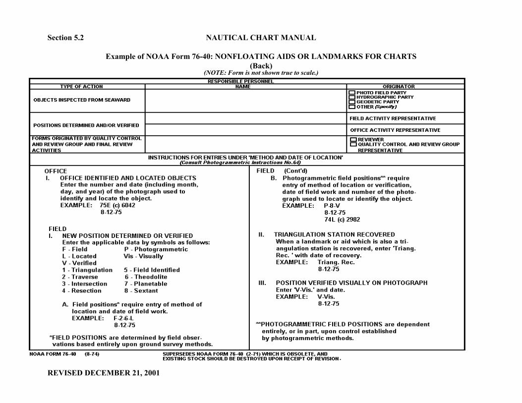
Geographic Positions of Aids to Navigation Provided by an NOS Field Survey: NOS FieldParty reports which list the geographic positions of lights or daybeacons on NOAA Form 76-40 (seeexample on following page) shall also be considered an official source of an aid revision. When fixedaids are reported as such, it shall be the responsibility of the cartographer to determine the mostcurrent and correct position of the aid. The official Date of Location and positional accuracy shallbe the primary determinants. The Nautical Data Branch , upon the receipt of such a document, shallfurnish USCG Headquarters and the affected USCG local district a copy of the respective form 76-40.
Documents from sources other than the USCG, NOS, the Canadian Coast Guard and the SaintLawrence Seaway Development Corporation, and which report the addition, revision or deletion ofaids to navigation shall be forwarded to the Nautical Data Branch (NDB) for verification with theUSCG. Aid revisions reported from non-official sources shall not be applied before documentationciting USCG approval is received in NDB.
The Lateral System: Aids to navigation are not established in navigable waters haphazardly, butare deployed in accordance with a prescribed pattern. The United States has adopted the lateralsystem, IALA (International Association of Lighthouse Authorities) in which the colors, shapes, andnumbers of lights, buoys, and daybeacons are determined by their location in relation to safe waterand by the general direction taken by the mariner when approaching port from seaward.
The lateral system of aid to navigation identification is also applied to (a.) offshore buoys and lightslocated along those coasts and (b.) traffic routes which do not lead distinctly from seaward or towardheadwaters. However, the color and number designations are applied so that even-numbered aidsmark the starboard side when proceeding in a southerly direction along the Atlantic coast, in anortherly and westerly direction along the Gulf coast, and in a northerly direction along the Pacificcoast. The aids in the Intracoastal Waterway are similarly marked in the direction proceeding fromthe north Atlantic states to the lower coast of Texas. These markings are regardless of the compassheadings of individual sections of the waterway.
Local Notice to Mariners (LNM) vs. Weekly Notice to Mariner (NM): In general, most changesaffecting newly established, revised, or deleted aids to navigation are first applied to a chart from theLocal Notice to Mariners (LNM). The Local Notice to Mariners is a publication issued by eachUnited States Coast Guard District for the purpose of disseminating information affecting navigationsafety within the district. Although the LNM is usually published weekly, it may be published asoften as required.
The LNM shall serve as the primary source document for the application and revision of all aids tonavigation falling in United States waters and under the jurisdiction of the USCG.
angiew
angiew

NAUTICAL CHART MANUAL Section 5.2
Example of NOAA Form 76-40: NONFLOATING AIDS OR LANDMARKS FOR CHARTS(Front)
(NOTE: Form is not shown true to scale.)
REVISED DECEMBER 21, 2001
Section 5.2 NAUTICAL CHART MANUAL
Example of NOAA Form 76-40: NONFLOATING AIDS OR LANDMARKS FOR CHARTS(Back)
(NOTE: Form is not shown true to scale.)
REVISED DECEMBER 21, 2001

NAUTICAL CHART MANUAL Section 5.2
REVISED JANUARY 8, 2004
Newly established aids to navigation shall not be charted unless a Light List number has beenassigned to the aid when it is first published in the LNM. As a general rule, only those aids whichare now included or shall in the future be included in the USCG Light List, are to be charted onMCD charts. However, aids established by neighboring foreign countries, aids having reliablemaintenance authorities (such as those established by the military), and environmental buoys whichfall beyond Light List limits may also be charted. In addition, radar reflectors, lights, and soundsignals shall continue to be charted for those features which are not specifically intended for use innavigation, whether or not the feature is listed in the Light List. Features in this category includefloats, targets, platforms, dredging range markers and data-collecting buoys.
If a new edition of a Light List includes an aid change that was not published in a LNM, the changeshould be verified by the Update Service Branch before the chart is revised.
The Weekly Notice to Mariners (NM) is produced by the National Geospatial-Intelligence Agency(NGA) and is a weekly publication prepared jointly with the National Ocean Service and the USCG.Although this publication also contains information concerning changes in aids to navigation, itemsaffecting navigation safety and selected items from the Local Notice to Mariners, it shall serve as asupplementary source for the application and revision of aids to navigation falling within the limitsof MCD charts.
The Weekly Notice to Mariners (NM) shall be used primarily to:
� Apply any additions, revisions and deletions of aids to navigation (and other items) which were not previously reported in a USCG Local Notice to Mariners (LNM).
� Apply all additions, revisions and deletions affecting aids to navigation (and other items) falling under the jurisdiction of neighboring foreign authorities (e.g., Cuba, Mexico, the Bahamas, Russia). NOTE: “Neighboring foreign authorities”, as mentioned in this paragraph, does not include Canada and waters falling under the jurisdiction of the Saint Lawrence Seaway Development Corporation. Changes to aids in these waters shall be provided in the Canadian Notice to Mariners.
ENC Bulletin. RE: Source Documents for ENC Aids to Navigation
USCG Local Notice to Mariners (LNM), NGA Weekly Notices to Mariners (NM) and fixed aids to navigation listed on NOAA Form 76-40 from NOS Field Party examinations shall serve as the official source documents for encoding all aids to to navigation to be displayed on Electronic Navigational Charts. These documents shall not only serve as the official source of recently reported aid additions and revisions, but they shall also serve as the source of information acquired from historical document research, performed for the purpose of ensuring the current status of a previously charted aid is accurately encoded in the ENC database.
angiew

Section 5.2 NAUTICAL CHART MANUAL
REVISED DECEMBER 21, 2001
Symbolization: The symbols to be used in charting aids to navigation are illustrated in Sections P, Q, Rand S of Chart No. 1, Nautical Chart Symbols Abbreviations and Terms. Additional informationconcerning the proper aid symbolization is provided in the back sections of Chart No.1, pages 96 through99. The symbols and information presented on these (Chart No. 1) pages are to be used exclusively forcharting those aids which are: (a) intended for use in normal navigation and, (b) are listed in the USCGLight List.
NOTE: To chart those aids which are not specifically intended for use in general navigation, and whichare not in the USCG Light List, the appropriate landmark symbol and identifying label shall be used.
ENC Bulletin. RE: IHO S-57 Appendix B.1, Annex D
IHO S-57 Appendix B.1, Annex D, is the ENC equivalent to the National Ocean Service’s Chart No. 1, Nautical Chart Symbols Abbreviations and Terms. It is the publication which contains the official library of symbols and color specifications of all ENC objects to be displayed on Electronic Chart Display and Information Systems (ECDIS).
Characteristics and Labels: The characteristics of an aid to navigation are the audible, visual orelectronic signals displayed by an aid to navigation to assist in its identification. Generally allcharacteristics of an aid to navigation are charted, except for the specific omissions and exceptionsdescribed in this chapter. Characteristics shall be charted in the form of a label and shall be shown in black7 pt. Swiss Regular Vertical type (fixed aids to navigation) or 7 pt. Swiss Regular Italic type (floating aidsto navigation). In congested areas, a type size not less than 5 pt. Swiss Regular may be substituted.
ENC Bulletin. RE: Characteristics of ENC Aids to Navigation
Within the ENC environment, there are several general categories into which the characteri- stics of aids to navigation are encoded. These categories, called attributes, not only identify the characteristics typically portrayed on an MCD chart, they also provide a more thorough description (physical and informative) of the aid as it exists in the real world. For example, an attribute may provide the type of structure supporting the aid, the intended purpose of the aid, the name of the aid and the source (and source date) which establishes, revises or relocates an aid.
angiew
angiew
angiew
angiew
angiew
angiew

NAUTICAL CHART MANUAL Section 5.2
REVISED DECEMBER 21, 2001
Location: All aids shall be charted in the true geographic positions reported in the official sourcedocument. Aids shall not be charted in the positions provided in the USCG Light List.
Aids shall not be moved off ranges or natural objects.
Aids and their identifying characteristics must be charted so as to be readily identifiable by the chartuser.
When buoys, daybeacons, and lights are to be charted along channels, the respective symbols (andlabels) should be placed so that channel limits are kept clear. Those aids to navigation which arecharted along dredged channels and which overprint due to being placed in their true positions, may,with the approval of the Production Branch Chief, be separated by a distance of 0.5 mm. Thisprocedure, however, shall seldom be necessary for many aid symbols are still legible, even whenoverprinted.
Aids and their identifying characteristics must be charted so that they are identified readily by thechart user and are not obscured by less important information.
ENC Bulletin. RE: Geographic Positions of ENC Aids to Navigation
Within the ENC environment, all aids to navigation shall be encoded at the official geographic position provided in the source document and are not to be moved because of overprinting which may tentatively occur on a paper/raster chart.
Temporary and Seasonal Aids/Changes: Temporary aids shall not be charted unless they havebeen assigned a Light List number. Exceptions shall be handled on a case-by-case basis.
Temporary changes or defects in aids to navigation are also not to be indicated on MCD charts. Thefollowing standard “temporary defects” CAUTION note stating this practice, shall be placed on allcharts and shall be shown in black 7 pt. Swiss Light type, 2" wide format:
CAUTION
Temporary changes or defects in aids tonavigation are not indicated on this chart. See
Local Notice to Mariners.
Seasonal aids/changes are those aids and characteristics which are established or changed for thewinter navigation season. These changes are also considered temporary and therefore shall not becharted. However, specific details for important aids, such as seasonal fog signals at major aids,
angiew
angiew
angiew

Section 5.2 NAUTICAL CHART MANUAL
REVISED DECEMBER 21, 2001
shall be charted in all geographic areas. The following paragraph pertaining to seasonal aids tonavigation, shall be added to the “temporary defects” CAUTION note on all charts falling withinthe Great Lakes and on east coast charts from Cape Henry, Virginia, northward. The entire note shallbe shown in black 7 pt. Swiss Light type, 2" wide format and shall read:
CAUTION Temporary changes or defects in aids tonavigation are not indicated on this chart. See
Local Notice to Mariners. During some winter months or when endan-
gered by ice, certain aids to navigation are replaced by other types or removed. For details, see U.S. Coast Guard Light List.
The Update Service Branch shall ascertain when the above note is applicable for areas outside thedesignated geographic areas listed above.
ENC Bulletin. RE: Seasonal ENC Aids to Navigation
Although seasonal aids and changes are considered temporary, and are only provided for on an MCD paper/raster chart through the application of the “seasonal aids” note, seasonal information shall be encoded individually for each affected ENC aid to navigation. The attributes which shall contain the seasonal information are Status (STATUS), Period Date Start (PERSTA) and Period Date End (PEREND). Status (STATUS) shall be encoded with a value of five (5) to indicate a periodic/intermittent status of the aid. Period Date Start (PERSTA) shall be encoded with the starting date of the active season of the aid. Period Date End (PEREND) shall be encoded with the ending date of the active season.
On Alaskan charts, specific details published in Notice to Mariners concerning seasonal aids shallbe charted by individual or general notes. Specific details for important aids, such as seasonal fogsignals, shall be charted on major aids charted on Alaskan charts.
Radar Reflectors: A radar reflector is a special fixture or reflective material fitted to orincorporated into the design of certain aids. Its purpose is to enhance the aid’s capability ofreflecting radar energy. Since radar reflectors have been placed on nearly all USCG maintainedfloating aids, the label “Ra Ref” shall be omitted as part of the charted characteristics of floatingaids, and the following general note shall be added to all MCD charts. The note shall be shown inblack 7 pt. Swiss Light and shall read:
RADAR REFLECTORS Radar Reflectors have been placed on many
floating aids to navigation. Individual radar reflector identification on these aids has been omitted from this chart.
angiew
angiew

NAUTICAL CHART MANUAL Section 5.2
REVISED DECEMBER 21, 2001
Fixed aids to navigation which are equipped with radar reflectors, shall contain the label “Ra Ref”as part of the associated label.
For those features which are not specifically intended for navigation (e.g. floats, targets, platforms,dredging range markers and data collection buoys) and which are equipped with radar reflectors, thelabel “Ra Ref” shall also be charted as part of the associated label. The “Ra Ref” label shall becharted for these features whether the feature is listed in the Light List or not.
The radar reflector symbol S 4 in Chart No. 1 shall no longer be used on NOS nautical charts.
ENC Bulletin. RE: Radar Reflectors and Aids to Navigation
A radar reflector shall not be encoded as a separate ENC object when the reflector is attached to an aid to navigation. In this situation, the existence of the radar reflector shall be indicated by encoding (with the proper value), the Conspicuous, radar (CONRAD) attribute associated with the aid’s structure.
Articulated Aids: Articulated aids are designed primarily to mark narrow channels in depths of upto 60 feet. They consist of a vertical pipe structure that oscillates around a universal couplingconnected to a sinker. The structure is kept upright by the buoyancy of a submerged flotationchamber.
There are two types of articulated aids which are currently charted by MCD, an articulated light andan articulated daybeacon. See Sections 5.3.3 and 5.6 for more information.
ICW Aids: Where the Intracoastal Waterway (ICW) coincides with another waterway, the USCGuses yellow squares and triangles to indicate lateral significance on dual purpose aids to navigation.
Yellow triangles are used on all buoys and daymarks that should be passed on the starboard (right)side of the vessel.
Yellow squares are used on all buoys and daymarks that should be passed on the port (left) side ofthe vessel.
Non-lateral aids to navigation such as safewater marks, isolated danger marks and range marks willdisplay a horizontal yellow band.
These yellow triangles, squares and horizontal bands do not affect the symbology of the charted red
angiew
angiew
angiew
angiew
angiew
angiew
angiew
angiew

Section 5.2 NAUTICAL CHART MANUAL
REVISED DECEMBER 21, 2001
or green aids. However, the following notes shall be shown on the appropriate charts dependingupon the range of the ICW covered by the chart. The notes shall be shown in magenta, 7 pt. SwissLight type.
New Jersey ICW - Charts: 12324, 12316
INTRACOASTAL WATERWAY AIDS The U.S. Aids to Navigation System is de- signed for use with nautical charts, and the exact meaning of an aid to navigation may not be clear unless the appropriate chart is consulted. Aids to navigation marking the Intracoastal Waterway exhibit unique yellow symbols to distinguish them from aids marking other water- ways. When following the Intracoastal Waterway southward from Manasquan Inlet to Cape May, NJ, aids with yellow triangles should be kept on the starboard side of the vessel and aids with yellow squares should be kept on the port side of the vessel. A horizontal yellow band provides no lateral information, but simply identifies aids to navi- gation as marking the Intracoastal Waterway. All lights and lighted buoys marking the Intra- coastal Waterway on this chart show a flash every four seconds, unless otherwise specified. The aids marking tributary channels, in gen- eral, are maintained by the state of New Jersey.
Norfolk, Va. to Cross Bank, FL. ICW - Charts: 12205,12206, 11553, 11541, 11534, 11518, 11507, 11491, 11489, 11485, 11472, 11428, 11467, 11451, 11463, 11465
INTRACOASTAL WATERWAY AIDS The U.S. Aids to Navigation System is de- signed for use with nautical charts, and the exact meaning of an aid to navigation may not be clear unless the appropriate chart is consulted. Aids to navigation marking the Intracoastal Waterway exhibit unique yellow symbols to distinguish them from aids marking other water- ways. When following the Intracoastal Waterway southward from Norfolk, Va. to Cross Bank in Florida Bay, aids with yellow triangles should be kept on the starboard side of the vessel and aids with yellow squares should be kept on the port side of the vessel. A horizontal yellow band provides no lateral information, but simply identifies aids to navi- gation as marking the Intracoastal Waterway.

NAUTICAL CHART MANUAL Section 5.2
REVISED DECEMBER 21, 2001
Okeechobee Waterway - Charts: 11427, 11428, 11472
INTRACOASTAL WATERWAY AIDS The U.S. Aids to Navigation System is de- signed for use with nautical charts, and the exact meaning of an aid to navigation may not be clear unless the appropriate chart is consulted. Aids to navigation marking the Intracoastal Waterway exhibit unique yellow symbols to distinguish them from aids marking other water- ways. When following the Okeechobee Waterway westward from St. Lucie Inlet to Fort Myers, FL, aids with yellow triangles should be kept on the starboard side of the vessel and aids with yellow squares should be kept on the port side of the vessel. A horizontal yellow band provides no lateral information, but simply identifies aids to navi- gation as marking the Okeechobee Waterway.
Caloosahatchee River to Anclote, FL. ICW - Charts 11427, 11425, 11411
INTRACOASTAL WATERWAY AIDS The U.S. Aids to Navigation System is de- signed for use with nautical charts, and the exact meaning of an aid to navigation may not be clear unless the appropriate chart is consulted. Aids to navigation marking the Intracoastal Waterway exhibit unique yellow symbols to distinguish them from aids marking other water- ways. When following the Okeechobee Waterway westward from the Caloosahatchee River to, Anclote, FL, aids with yellow triangles should be kept on the starboard side of the vessel and aids with yellow squares should be kept on the port side of the vessel. A horizontal yellow band provides no lateral information, but simply identifies aids to navi- gation as marking the Intracoastal Waterway.
Carabelle, FL. to Brownsville, TX. ICW - Charts 11404, 11402, 11393, 11390, 11385, 11378, 11374, 11372, 11367, 11365, 11355, 11354,
11345, 11352, 11350, 11348, 11331, 11326, 11324, 11322, 11319, 11315, 11314, 11308,
11306, 11303, 11302
INTRACOASTAL WATERWAY AIDS The U.S. Aids to Navigation System is de- signed for use with nautical charts, and the exact meaning of an aid to navigation may not be clear unless the appropriate chart is consulted. Aids to navigation marking the Intracoastal Waterway exhibit unique yellow symbols to distinguish them from aids marking other water- ways. When following theIntracoastal Waterway westward from Carrabelle, FL to Brownsville, TX, aids with yellow triangles should be kept on the starboard side of the vessel and aids with yellow squares should be kept on the port side of the vessel. A horizontal yellow band provides no lateral information, but simply identifies aids to navi- gation as marking the Intracoastal Waterway.
Section 5.2 NAUTICAL CHART MANUAL
REVISED DECEMBER 21, 2001
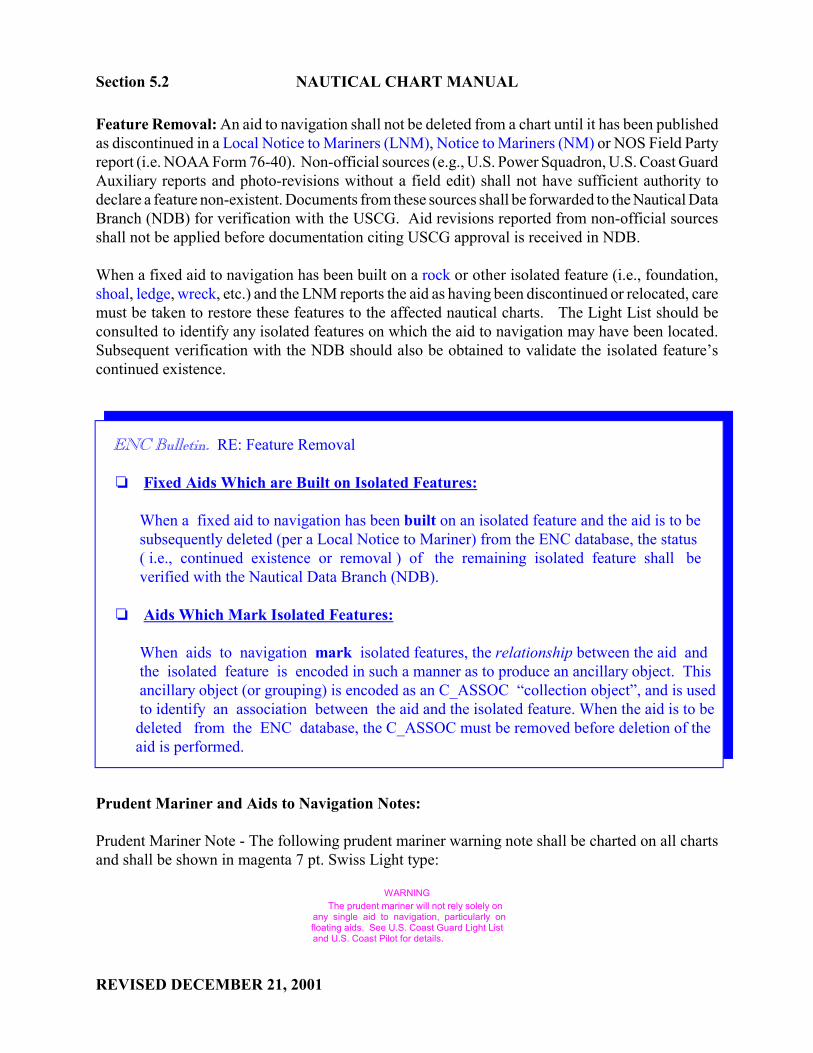
Feature Removal: An aid to navigation shall not be deleted from a chart until it has been publishedas discontinued in a Local Notice to Mariners (LNM), Notice to Mariners (NM) or NOS Field Partyreport (i.e. NOAA Form 76-40). Non-official sources (e.g., U.S. Power Squadron, U.S. Coast GuardAuxiliary reports and photo-revisions without a field edit) shall not have sufficient authority todeclare a feature non-existent. Documents from these sources shall be forwarded to the Nautical DataBranch (NDB) for verification with the USCG. Aid revisions reported from non-official sourcesshall not be applied before documentation citing USCG approval is received in NDB.
When a fixed aid to navigation has been built on a rock or other isolated feature (i.e., foundation,shoal, ledge, wreck, etc.) and the LNM reports the aid as having been discontinued or relocated, caremust be taken to restore these features to the affected nautical charts. The Light List should beconsulted to identify any isolated features on which the aid to navigation may have been located.Subsequent verification with the NDB should also be obtained to validate the isolated feature’scontinued existence.
ENC Bulletin. RE: Feature Removal
� Fixed Aids Which are Built on Isolated Features: When a fixed aid to navigation has been built on an isolated feature and the aid is to be subsequently deleted (per a Local Notice to Mariner) from the ENC database, the status ( i.e., continued existence or removal ) of the remaining isolated feature shall be verified with the Nautical Data Branch (NDB).
� Aids Which Mark Isolated Features: When aids to navigation mark isolated features, the relationship between the aid and the isolated feature is encoded in such a manner as to produce an ancillary object. This ancillary object (or grouping) is encoded as an C_ASSOC “collection object”, and is used to identify an association between the aid and the isolated feature. When the aid is to be deleted from the ENC database, the C_ASSOC must be removed before deletion of the aid is performed.
Prudent Mariner and Aids to Navigation Notes:
Prudent Mariner Note - The following prudent mariner warning note shall be charted on all chartsand shall be shown in magenta 7 pt. Swiss Light type:
WARNING The prudent mariner will not rely solely on any single aid to navigation, particularly on
floating aids. See U.S. Coast Guard Light List and U.S. Coast Pilot for details.
angiew
angiew
angiew
angiew
angiew
angiew

NAUTICAL CHART MANUAL Section 5.2
REVISED DECEMBER 21, 2001
Aids to Navigation Note - The following aids to navigation note shall be charted on all charts andshall be shown in black 7 pt. Swiss Light type:
AIDS TO NAVIGATION Consult U.S. Coast Guard Light List for
supplemental information concerning aids to navigation.
5.2.1 Application of Corrections from Notice to Mariners
All corrections applied to the raster chart files from the LNM/NM or other sources shall be shownusing standard symbols, notes, and characteristics. Changes to aids are recorded in the NM UpdateService CRIT database.
5.2.1.1 Update Service Branch (USB)
The Update Service Branch is responsible for the following:
� evaluating and taking appropriate corrective action in applying LNM/NM changesto the raster chart files.
� recording LNM/NM changes in a CRIT database
� marking each item in the LNM/NM to indicate that the appropriate corrective actionhas been taken in accordance with established procedures.
� keeping track of the number of corrections made to a chart from a LNM/NM inaccordance with the following:
Correction Numeric Count
(a) adding a symbol, its color and characteristics..................................................................1
(b) deleting a symbol, its color and characteristics..................................................................1
(c) revising an existing aid location or characteristic......................................................................2
(d) history cross-referencing (i.e., coordinating the published LNM with the originating source
material, e.g., tabulations).......................................................2
Section 5.2.1.1 NAUTICAL CHART MANUAL
REVISED JANUARY 8, 2004
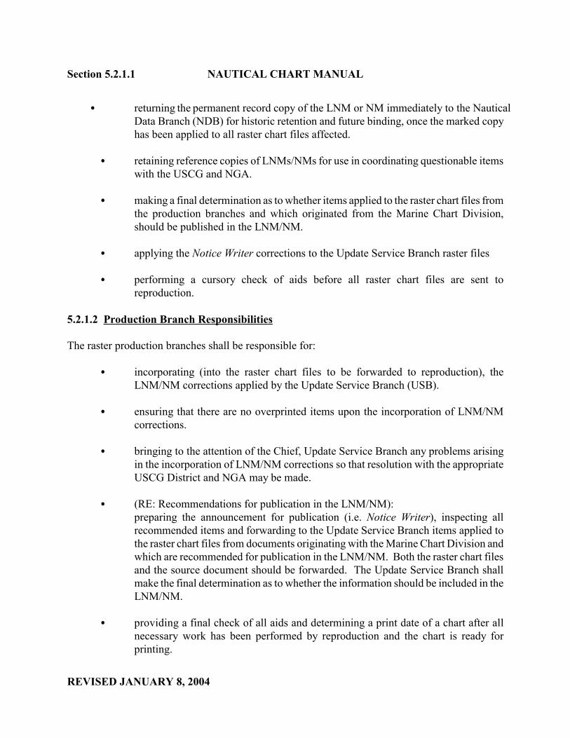
� returning the permanent record copy of the LNM or NM immediately to the NauticalData Branch (NDB) for historic retention and future binding, once the marked copyhas been applied to all raster chart files affected.
� retaining reference copies of LNMs/NMs for use in coordinating questionable itemswith the USCG and NGA.
� making a final determination as to whether items applied to the raster chart files fromthe production branches and which originated from the Marine Chart Division,should be published in the LNM/NM.
� applying the Notice Writer corrections to the Update Service Branch raster files
� performing a cursory check of aids before all raster chart files are sent toreproduction.
5.2.1.2 Production Branch Responsibilities
The raster production branches shall be responsible for:
� incorporating (into the raster chart files to be forwarded to reproduction), theLNM/NM corrections applied by the Update Service Branch (USB).
� ensuring that there are no overprinted items upon the incorporation of LNM/NMcorrections.
� bringing to the attention of the Chief, Update Service Branch any problems arisingin the incorporation of LNM/NM corrections so that resolution with the appropriateUSCG District and NGA may be made.
� (RE: Recommendations for publication in the LNM/NM):preparing the announcement for publication (i.e. Notice Writer), inspecting allrecommended items and forwarding to the Update Service Branch items applied tothe raster chart files from documents originating with the Marine Chart Division andwhich are recommended for publication in the LNM/NM. Both the raster chart filesand the source document should be forwarded. The Update Service Branch shallmake the final determination as to whether the information should be included in theLNM/NM.
� providing a final check of all aids and determining a print date of a chart after allnecessary work has been performed by reproduction and the chart is ready forprinting.

NAUTICAL CHART MANUAL Section 5.2.1.2
REVISED DECEMBER 21, 2001
ENC Bulletin. RE: ENC Responsibilities
� Initial Encoding of a Chart:
During the initial encoding of a MCD chart, it may be necessary to perform historical document research to ensure the current status of a previously charted aid is accurately encoded in the ENC database. Although LNMs / NMs / NOAA Form 76-40 are the primary source documents for the position and characteristics of aids, two (2) MCD database listings exist which have incorporated changes reported in the LNM/NM /NOAA Form76-40 (and other official sources), and which may facilitate the encoding of all affected aids.
These database listings are the CRIT (Aid to Navigation CRITical Corrections) and the DIPFILE (Discrete Independent Point FILE).
The CRIT database began in 1987 incorporating aid changes reported in LNMs /NMs and continues today to serve as the official aids to navigation history of cartographic work.
The DIPFILE, established in1972 and maintained until1986 was a database which contained the source and geographic positions of not only all aids to navigation as they existed on MCD charts in 1972 through 1986, it also contained the source and geographic position of other cartographic features such as landmarks, wrecks and obstructions.
To perform the initial encoding of all aids to navigation which are currently charted on a MCD chart, the following resources shall be used and in accordance with the specified order:
(1) CRIT database listing (2) DIPFILE (3) the respective chart
� Continual Maintenance:
During the continual maintenance phase of an ENC, all LNM/NM corrections shall be applied to the ENC database by obtaining the appropriate CRIT database listing and applying all specified corrections. The actual LNM/NM may be obtained to encode aid attributes which are not available on the CRIT listing, but the LNM/NM shall not be used to apply changes independently of the CRIT listing and the Update Service Branch.
When fixed aids are reported on NOAA Form 76-40, it shall be the responsibility of the cartographer to determine the most current and correct position of the aid. The official Date of Location and positional accuracy shall be the primary determinants. The Nautical Data Branch , upon the receipt of such a document, shall furnish USCG Headquarters and the affected USCG local district a copy of the respective form 76-40.

Section 5.2.2 NAUTICAL CHART MANUAL
REVISED DECEMBER 21, 2001
5.2.2 Hurricane and Tropical Storm Warning Note The following note shall be placed on charts covering any part of Biscayne Bay or Hawk Channel,Florida and the Gulf Coast from Longitude 89° West to Longitude 95° West.
CAUTION Hurricanes and tropical storms disturb objects on the
sea floor and cause considerable damage to offshore structures, aids to navigation and moored vessels resulting in extensive debris being submerged in unknown locations. Wrecks and submerged obstructions may have been
displaced from charted locations, and pipelines may have become uncovered or moved due to the force of storm surge. Aids to navigation may not be reliable immediately following such storms. Mariners are urged to exercise
extreme caution and are requested to report aids to navigation discrepancies and hazards to navigation to the
nearest United States Coast Guard Unit.
This note shall print in black, 7 point Swiss Light style type, set 2 1/2 or 3 inches wide.
(This space is intentionally blank.)
5.3 Lights
Lights on fixed structures are placed to assist the mariner in position determination, to mark channels,and to warn of dangers or obstructions to navigation. Lights are identified on charts both by their light

UNITED STATES DEPARTMENT OF COMMERCE National Oceanic and Atmospheric Administration NATIONAL OCEAN SERVICE Office of Coast Survey
Silver Spring, Maryland 20910-3282
MARCH 14, 2002
MEMORANDUM FOR: All CartographersMarine Chart Division
FROM: Fannie B. PowersChief, Quality Assurance, Plans and Standards Branch
SUBJECT: Nautical Chart Manual: Section Number Revisions; Correction Pages- Pages 5-5 and 5-6
Effective immediately, the following attachment replaces pages 5-5 and 5-6 in the Nautical ChartManual, Volume 1, Part 2, Seventh (1992) Edition.
The attachment:
1. Revises the section numbers of Sections 5.2.1 and 5.2.2 to Sections 5.3.1 and 5.3.2respectively,
2. Improves the legibility of the graphics on pages 5-5 and 5-6.
3. Changes the term “digital” to the term “raster” in paragraph 5.3.2.
Pages 5-5 and 5-6 are to be inserted into the Nautical Chart Manual, Volume 1, Part 2, Seventh(1992) Edition immediately after page 5-4.
Attachment

NAUTICAL CHART MANUAL Section 5.3
REVISED MARCH 14, 2002
characteristics and magenta flare. Lights of different colors and having different sequences andlengths of light and dark periods help mariners distinguish charted lights and locate their position.The source of new or revised light positions and characteristics are generally the LNM and NM, theUSCG Light List, and the Canadian NM and List of Lights, Buoys and Fog Signals. See Section 5.4,Buoys, for changes in colors of lights (e.g., the phasing out of white lights) in conformance with theIALA Maritime Buoyage Systems. The symbols used to chart lights are shown in section P of ChartNo. 1.
5.3.1 Charting Practices
The position of a light shall be shown by a black 0.75-mm dot, with a magenta flare drawn about 1mm from the light dot (P 1). The orientation of the flare should be directed toward the label, ifpossible, and should avoid obscuring other detail. Flare orientation should, in general, be at the sameangles as the orientation of buoy symbols (see Section 5.4.1). In the case of a leading light, the flaremay be oriented seaward along the line (P 1).
When positions of fixed aids are listed on NOAA Form 76-40, Nonfloating Aids or Landmarks forCharts, the cartographer must determine their correct, current position. Date of location andpositional accuracy are the primary determinants. NDB shall furnish USCG Headquarters and theaffected USCG Local District with a copy of Form 76-40. MCD shall not initiate a NM in thisinstance.
The Light List should be consulted when the LNM reports a light has been discontinued or relocatedand the light structure removed. If the Light List states that the light was located on a foundation,shoal, ledge, wreck, etc., this feature should be charted. In the case of a discontinued lighthouse, thelighthouse structure itself may be charted as a landmark, e.g., "TOWER (ABAND LT HO)". Thesymbol "PA" (position approximate) is added when a destroyed light is reported in the NMas having been reconstructed and the exact fixed position has not been established.
5.3.2 Light Characteristics
The characteristics and number of a light should be shown on the digital chart files in the exactposition they will occupy on the finished chart. If the name of the light appears in the Light List inbold type and space permits, it should be shown above the characteristics. How the variouscharacteristics of a light, which identify it as fixed or having a particular flash configuration, itsvisibility and its color, are charted as shown in P 10.1 through P 10.11 in Chart No. 1.
Two lights on the same structure should be labeled by their separate characteristics even though bothare the same, e.g.:
(Fl R)(Fl R)
angiew
angiew
angiew
angiew
angiew
angiew
angiew
angiew
angiew
angiew
angiew
angiew
angiew

Section 5.3.2 NAUTICAL CHART MANUAL
REVISED MARCH 14, 2002
Large-scale charts shall provide complete information as to light characteristics. On smaller-scalecharts charts covering only coastal areas, complete information regarding characteristics should begiven for those lights which will be used in coastwise navigation.
1. Charted Characteristics
The various identifying characteristics of lights that are charted are discussed below in general terms.For a complete list of characteristics and their charted abbreviations, see Chart No. 1 and the LightList.
Light Name
The characteristics and number of a light should be shown in 7 pt. Swiss Regular type except incongested areas where 6 pt. type may be used. The light name should be shown in 7 pt. SwissRegular, vertical type..
Example:
SKUNK BAY LTF R 210ftPriv
Flash Characteristics (P 10.1 - P 10.11)
A fixed light shows continuously and steadily and is charted with the label "F".
An occulting light displays a total duration of light in a period longer than the total duration ofdarkness and the intervals of darkness (eclipses) are usually of equal duration. An occulting light ischarted with the label "Oc".
An isophase light shows equal durations of light and darkness and is charted with the label "Iso".
A flashing light has a total duration of light in a period shorter than the total duration of darknessand the appearance of light (flashes) usually of equal duration. A flashing light is charted with thelabel "Fl".
A group-flashing light displays a group of flashes, specified in number, regularly repeated, andcharted with the label "Fl (3)".
A composite group-flashing light is similar to a group-flashing light except that successive groupsin a period have different numbers of flashes. A composite group-flashing light is charted with thelabel "Fl (3+1)".
A continuous quick light has regularly repeated flashes of not less than 50 flashes per minute butless than 80 flashes per minute. A continuous quick light is charted with the label "Q".
angiew
angiew

UNITED STATES DEPARTMENT OF COMMERCE National Oceanic and Atmospheric Administration NATIONAL OCEAN SERVICE Office of Coast Survey
MAY 8, 2002
MEMORANDUM FOR: All CartographersMarine Chart Division
FROM: Fannie B. PowersChief, Quality Assurance, Plans and Standards Branch
SUBJECT: Nautical Chart Manual: Page Header Number Revision
Effective immediately, the following attachment replaces pages 5-7 and 5-8 in the Nautical ChartManual, Volume 1, Part 2, Seventh (1992) Edition. The attachment revises the page header numberfrom Section 5.2.2 to Section 5.3.2,
Pages 5-7 and 5-8 are to be inserted into the Nautical Chart Manual, Volume 1, Part 2, Seventh(1992) Edition immediately after page 5-6.
Attachment

NAUTICAL CHART MANUAL Section 5.3.2
REVISED MAY 8, 2002
An interrupted quick light has sequences of flashes interrupted by regularly repeated eclipses ofconstant and long duration. An interrupted quick light is charted with the label "IQ".
An alternating light displays different colors alternating and is charted with the label "Al W R".
Color (P 11.1 - P 11.8)
The color of lights shall be shown using abbreviations (R, G, etc.). They shall be charted in 7 pt.Swiss Regular type.
Generally, white lights are not labeled as to color; thus charted lights with no color indication canbe presumed to be white. However, where a light exhibits more than one color, including white (asin some sector lights and in alternating lights), the abbreviation "W" must be shown.
Amber lights are charted as yellow, i.e., "Y".
Period (P 12)
The period a light takes to exhibit a full sequence of phases is expressed in seconds, e.g., "15s".Periods will be charted to the nearest tenth of a second expressed as a decimal.
Height (P 13)
The height of a light is the vertical distance between the light source and the shoreline referencedatum (normally MHW, see Section 2.8). Height is shown in feet using the abbreviation "ft" excepton metric charts, where height is shown in meters using the abbreviation "m".
Visibility (P 14)
A light's visibility is expressed in the Light Lists as the "nominal range." This is the maximumdistance a light may be seen in clear weather (meteorological visibility of 10 nautical miles) withoutregard for the height of the light or the height of the observer. The nominal range is charted innautical miles in coastal areas, e.g., "10M". The nominal range is charted in statute miles onnon-metric Great Lakes charts, e.g., "12StM". On Great Lakes metric charts, nominal range is givenin nautical miles, e.g., "10NM". The visibility of range lights shall not be charted.
Converting a Nominal Range from Nautical Miles to Statute Miles
Conversion Value
When converting a nominal range from nautical miles to statute miles, a conversion value of 1.151shall be used (i.e., 1.151 x (nominal range in nautical miles) = nominal range in statute miles - beforerounding). This conversion value is the same value used by the U. S. Coast Guard and also
angiew
angiew
angiew
angiew
angiew
angiew

Section 5.3.2 NAUTICAL CHART MANUAL
REVISED MAY 8, 2002
contained in The American Practical Navigator, Publication No. 9, 1995.
NOTE: The conversion value is computed by dividing the number of feet containedin 1 nautical mile (6,076.11548) by the number of feet contained in 1 statute mile(5,280) and rounding to three significant digits.
Rounding
Resultant decimal values are rounded, not truncated. Decimal values equal to or greater than .5statute miles are rounded upward to the next whole unit. Decimal values less than .5 statute milesare rounded downward to the whole unit.
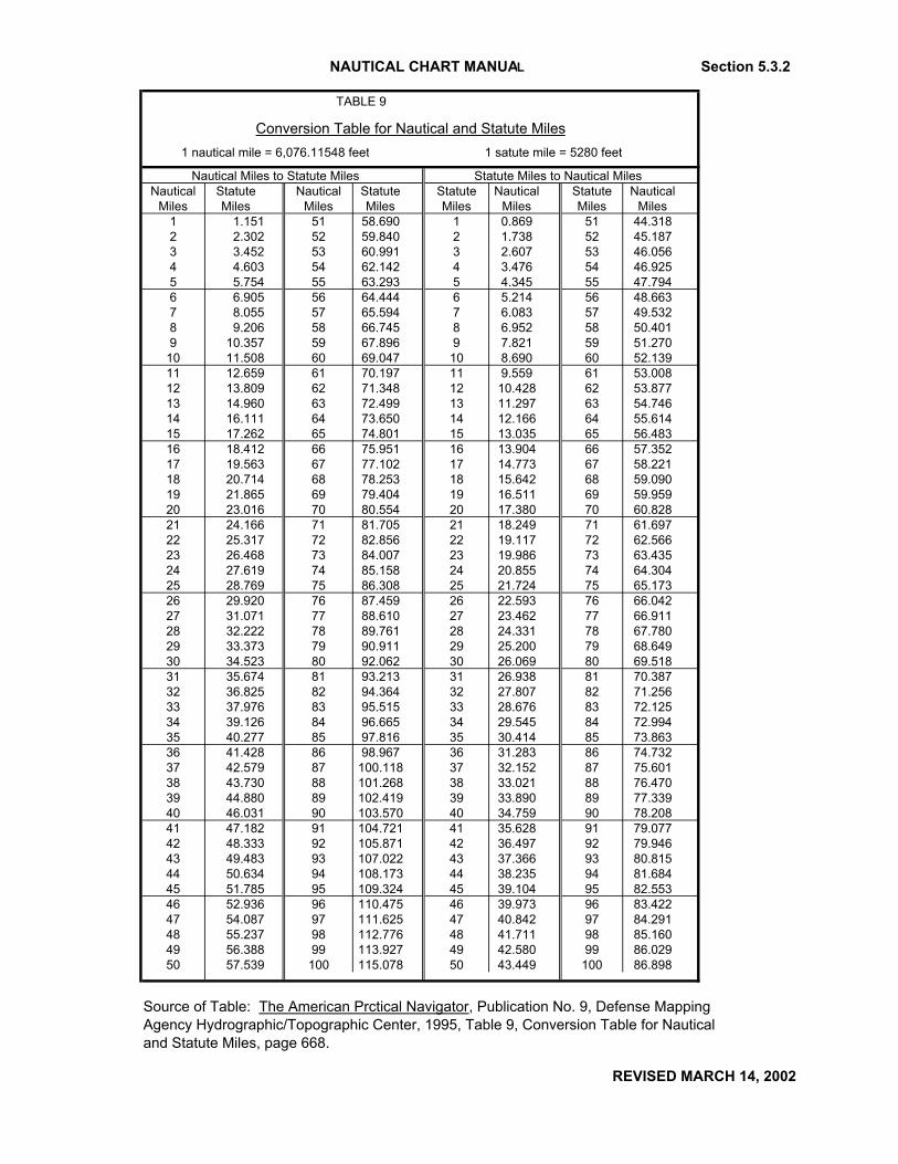
Conversion Table
The table on the following page is provided as an alternative to multiplying the nautical mile valueby the conversion value. The table provides conversions for all nautical mile values (columns 1 and3) to statute mile conversions (columns 2 and 4). The table contains statute mile conversions for allnautical mile values from 1 to 100 nautical miles. A value extracted from Table 9 must be roundedaccording to the established conventions provided in the previous section.
angiew

UNITED STATES DEPARTMENT OF COMMERCE National Oceanic and Atmospheric Administration NATIONAL OCEAN SERVICE Office of Coast Survey
Silver Spring, Maryland 20910-3282
MARCH 14, 2002
MEMORANDUM FOR: All CartographersMarine Chart Division
FROM: Fannie B. PowersChief, Quality Assurance, Plans and Standards Branch
SUBJECT: Nautical Chart Manual: Page Header Number Revision; CorrectionPages - Pages 5-9 and 5-10
Effective immediately, the following attachment replaces pages 5-9 and 5-10 in the Nautical ChartManual, Volume 1, Part 2, Seventh (1992) Edition.
The attachment:
1. Revises the page header number from Section 5.2.2 to Section 5.3.2,
2. Improves the legibility of Table 9, and,
3. Improves the legibility of the light characteristics’ table and legend on page 5-10.
Pages 5-9 and 5-10 are to be inserted into the Nautical Chart Manual, Volume 1, Part 2, Seventh(1992) Edition immediately after page 5-8.
Attachment
NAUTICAL CHART MANUAL Section 5.3.2
TABLE 9
Conversion Table for Nautical and Statute Miles 1 nautical mile = 6,076.11548 feet 1 satute mile = 5280 feet
Nautical Miles to Statute Miles Statute Miles to Nautical MilesNautical Statute Nautical Statute Statute Nautical Statute Nautical
Miles Miles Miles Miles Miles Miles Miles Miles1 1.151 51 58.690 1 0.869 51 44.3182 2.302 52 59.840 2 1.738 52 45.1873 3.452 53 60.991 3 2.607 53 46.0564 4.603 54 62.142 4 3.476 54 46.9255 5.754 55 63.293 5 4.345 55 47.7946 6.905 56 64.444 6 5.214 56 48.6637 8.055 57 65.594 7 6.083 57 49.5328 9.206 58 66.745 8 6.952 58 50.4019 10.357 59 67.896 9 7.821 59 51.270
10 11.508 60 69.047 10 8.690 60 52.13911 12.659 61 70.197 11 9.559 61 53.00812 13.809 62 71.348 12 10.428 62 53.87713 14.960 63 72.499 13 11.297 63 54.74614 16.111 64 73.650 14 12.166 64 55.61415 17.262 65 74.801 15 13.035 65 56.48316 18.412 66 75.951 16 13.904 66 57.35217 19.563 67 77.102 17 14.773 67 58.22118 20.714 68 78.253 18 15.642 68 59.09019 21.865 69 79.404 19 16.511 69 59.95920 23.016 70 80.554 20 17.380 70 60.82821 24.166 71 81.705 21 18.249 71 61.69722 25.317 72 82.856 22 19.117 72 62.56623 26.468 73 84.007 23 19.986 73 63.43524 27.619 74 85.158 24 20.855 74 64.30425 28.769 75 86.308 25 21.724 75 65.17326 29.920 76 87.459 26 22.593 76 66.04227 31.071 77 88.610 27 23.462 77 66.91128 32.222 78 89.761 28 24.331 78 67.78029 33.373 79 90.911 29 25.200 79 68.64930 34.523 80 92.062 30 26.069 80 69.51831 35.674 81 93.213 31 26.938 81 70.38732 36.825 82 94.364 32 27.807 82 71.25633 37.976 83 95.515 33 28.676 83 72.12534 39.126 84 96.665 34 29.545 84 72.99435 40.277 85 97.816 35 30.414 85 73.86336 41.428 86 98.967 36 31.283 86 74.73237 42.579 87 100.118 37 32.152 87 75.60138 43.730 88 101.268 38 33.021 88 76.47039 44.880 89 102.419 39 33.890 89 77.33940 46.031 90 103.570 40 34.759 90 78.20841 47.182 91 104.721 41 35.628 91 79.07742 48.333 92 105.871 42 36.497 92 79.94643 49.483 93 107.022 43 37.366 93 80.81544 50.634 94 108.173 44 38.235 94 81.68445 51.785 95 109.324 45 39.104 95 82.55346 52.936 96 110.475 46 39.973 96 83.42247 54.087 97 111.625 47 40.842 97 84.29148 55.237 98 112.776 48 41.711 98 85.16049 56.388 99 113.927 49 42.580 99 86.02950 57.539 100 115.078 50 43.449 100 86.898
Source of Table: The American Prctical Navigator, Publication No. 9, Defense Mapping Agency Hydrographic/Topographic Center, 1995, Table 9, Conversion Table for Nauticaland Statute Miles, page 668.
REVISED MARCH 14, 2002

Section 5.3.2 NAUTICAL CHART MANUAL
REVISED MARCH 14, 2002
Characteristic ChartingExample
Explanation
1. Flash characteristic (including number of flashes in a group flash)
Fl (3) group of 3 flashes
2. Color (omit if white) R red
3. Period 10s 10 seconds
4. Height 85ft 85 feet
5. Visibility 10M 10 miles
NumberThe assigned number or letter(s) of the structure, if any, should be shown in quotes, e.g., "2".
Privately Maintained (P 65)
In general only privately maintained lights that are listed in the USCG Light List should be charted.If lights established and maintained by private interests are charted, the same guidelines for addingcharacteristics to USCG lights apply, and they shall be labeled "Priv" in 7 pt. Swiss Regular type.The service name shall be charted on Military aids, e.g., "Navy". On small-scale charts, thisinformation may be omitted if it is charted on one or more large-scale charts covering the area, orwhere space is extremely limited.
2. Order of Characteristics
On large-scale charts, the characteristics of lights shall be shown in the following order:
The complete legend would appear on the charts in this form:
Fl (3) R 10s 85ft 10M "2"
3. Omission of Characteristics
Small-scale charts should show complete information regarding characteristics for major seacoastlights expected to be used in coastal navigation. However, where congestion is a problem, lessimportant lights may be shown in a more abbreviated format. When this is necessary, omissions oflight characteristics shall be made in the following order:
angiew

UNITED STATES DEPARTMENT OF COMMERCE National Oceanic and Atmospheric Administration NATIONAL OCEAN SERVICE Office of Coast Survey
Silver Spring, Maryland 20910-3282
MARCH 14, 2002
MEMORANDUM FOR: All CartographersMarine Chart Division
FROM: Fannie B. PowersChief, Quality Assurance, Plans and Standards Branch
SUBJECT: Nautical Chart Manual: Section Number Revision; CorrectionPages - Pages 5-11 though 5-14
Effective immediately, the following attachment replaces pages 5-11through 5-14 in the NauticalChart Manual, Volume 1, Part 2, Seventh (1992) Edition.
The attachment:
1. Revises the section number of Section 5.2.3 to Section 5.3.3,
2. Improves the legibility of the Articulated Aids Note, and,
3. Improves the legibility of all associated graphics.
Pages 5-11 though 5-14 are to be inserted into the Nautical Chart Manual, Volume 1, Part 2,Seventh (1992) Edition immediately after page 5-10.
Attachment

NAUTICAL CHART MANUAL Section 5.3.3
REVISED MARCH 14, 2002
1st, height: Fl (3) R 10s 10M "2"
2nd, period: Fl (3) R 10M "2"
3rd, number of flashes in group:Fl R 10M "2"
4th, daymark number: Fl R 10
5th, visibility: Fl R
5.3.3 Types of Lights
Some of the more common lights shown on nautical charts are described below.
Aeronautical Lights (P 60)
Aeronautical rotating white-and-green navigation lights usually associated with airports are the mostdependable lights during their hours of operation that can be shown on the nautical chart. They areoften the most conspicuous of the nonstrobe lights and their visibility range is usually greater thanthat of the lights established for marine navigation. Therefore, when an aeronautical light isrecommended for charting, it shall be charted as a light rather than as a landmark. Its position isindicated on the chart by a standard light dot with a magenta flare. The flare is used to emphasizea light's dependability, and thus is also used for USCG aids. The light symbol should beaccompanied by its characteristics and the label "AERO".
Since these lights are rotating, they are shown on the chart as "Rot". The color is shown by thestandard abbreviations used for nautical lights. The period, height, visibility, and number are notcharted.
A file with data for each rotating aeronautical light is maintained in NDB. This file gives the locationand color of these lights. The compiler should consult this file before making any changes to chartedaeronautical lights. If changes are made, the file should be corrected accordingly and, if necessary,the change should be published in the NM.
angiew
angiew

Section 5.3.3 NAUTICAL CHART MANUAL
REVISED MARCH 14, 2002
Articulated Lights (P 5)
Articulated lights are floating lights. They are basically a vertical pipe structure that oscillates arounda universal coupling connected to a sinker. The structure is kept upright by the buoyancy of asubmerged floating chamber.
The introduction of this type of aid to navigation, which is neither buoy nor fixed light, required anew symbol for charting. A black open circle 1.0 mm in diameter (the "approximate position"landmark symbol) is centered on the published position with a magenta flare. The open circle is usedinstead of a dot because the top of the structure may be displaced by an amount exceeding third-orderlight position accuracy (within 10 feet of its true position or reported to 0.1 second). The articulatedlight shall be labeled "Art" in Swiss Regular Italic type. The format for charting its characteristicsshall be the same as for buoys and daybeacons:
Art " 4" Fl R 4s
An explanatory note shall be placed on all charts with articulated aids. The note shall be in black 7pt. Swiss Light type, set 2" wide:
ARTICULATED AIDS An articulated aid to navigation consists of a
pipe structure that oscillates around a universalcoupling connected to a sinker. the structure iskept upright by the buoyancy of a submergedflotation chamber. It is designed primarily tomark narrow channels in depths of up to 60feet. All articulated aids are labeled “Art” .
Directional Lights (P 30)
Several types of directional lights are in use, all having a very narrow sector intended to mark adirection to be followed. The narrow sector may be flanked either by obscured or un-intensified light,or by lights of a different color or character.
When the main beam is flanked by obscured or un-intensified light, the central line of the sector shallbe charted like a range line (see Section 5.8, Ranges). When the major beam is flanked by a light ofa different color or character, the sector limits and arcs shall be charted, if possible.
A directional light normally shows three adjoining sectors of red, white, and green, in that order,reading clockwise. The center white beam is oriented to mark the preferred channel passage and isusually somewhat narrower than the red and green sectors. The bearings that define the arcs ofvisibility for these lights when looking from the mariner's point of view toward the light are
angiew
angiew
angiew

NAUTICAL CHART MANUAL Section 5.3.3
REVISED MARCH 14, 2002
published in the NM and in the Light List. An easy way to plot these bearings is to place the centerpoint of a compass on the light position dot, rotating the compass until 180E points true north. Then,reading clockwise, the bearings given for the sectors can be plotted. Specific bearings are sometimesnot given in the NM or Light List. The bearings may be described as "White when on centerline ofchannel, red when right and green when left of white beam entering from seaward." In this case, arange line shall be charted down the center of the channel from the light, with red and green sectorsshown on their respective sides of the range line.
The red and green sectors are obtained through the use of shields of these colors installed in the lensof the base light. They are shown on the chart by the legends "R SEC" and "G SEC" some distancefrom the light, within their arc of visibility. Where the chart scale is too small to show the directionallight sector, the light symbol only is shown.
The label "Directional Light" should be charted if this term is used in the Light List.
Leading Lights (P 20)
A leading light is similar to a range light (Section 5.8), except that it marks a channel with a singlelight (without a range line or ray lines) rather than with two separate lights. It usually has ahigh-intensity beam marking the safe channel which diminishes to far less intensity around theremainder of the horizon. It differs from a directional light in that it shows only one color of lightinstead of the three color sectors of the directional light.
Preferred Channel Lights (Q 130.1)
The light and the dayboard colors on a preferred channel light have lateral significance and provideguidance to the mariner for the channels emerging from a junction point. Primarily, the dayboard isfor day use and the light for night use. The light (which may also be a buoy or daybeacon) usuallyis placed in the "Y" formed by the merging channels. When the preferred channel in IALA RegionB is to the left of the light, the light will be red (or white) and the dayboard will be red on top andgreen (or black) on the bottom. If the preferred channel is to the right of the light, the light will begreen (or white) and the dayboard will be green (or black) above red. The colors would be reversedto indicate the preferred channel in IALA Region A.
Sector Lights (P 40, P 42, P 43)
Sector lights are used primarily to warn mariners of dangerous shoals or obstructions hazardous tosurface navigation. They are usually red, but may also be white or green. They are charted from theperspective of the mariner looking toward the light and should be plotted in the same manner asdescribed for directional lights, using dashed ray lines to show the limits of each sector. The ray linesshould be a reasonable length, though not necessarily to the limits of visibility and in no instancegreater than the visibility published in the Light List. The ray lines shall be discontinued when theyintersect the shoreline and would no longer be useful.
angiew
angiew
angiew
angiew
angiew
angiew
Section 5.3.3 NAUTICAL CHART MANUAL
REVISED MARCH 14, 2002
For obscured sectors (P 43), two bearings are normally given to show the limits of the obscuredsector. Both sector lines shall be charted even if part of the sector is obscured by an object higherthan the light.
Sector lights aid in safe navigation because the mariner can easily determine whether the vessel isin a safe position based on whether the sector light is visible.
Where the Light List shows different nominal range distances for sectored lights, the shorter of thetwo distances is charted. The length of charted sector lines are shown to this shorter distance or tothe terminating neatline or a land mass.
Strobe Lights
Many charted features are marked with very quick-flashing ultrabright lights. These are producedby a strobe-producing light device, usually a xenon gas condenser-discharge flash lamp or flash tube.Strobe lights are used on certain USCG-maintained aids to navigation and on aeronautical hazardssuch as stacks, towers, and buildings. The terms "flick" and "flash tube" as used in the LNM arelabeled "Strobe" on NOS charts. Aids published in the NM and Light List as well as landmarks withstrobe lights, shall include the label "Strobe" as well as the label of the particular feature.
The flash period of a strobe light is usually omitted because of its extremely short duration(considerably less than 1 second). Occasionally an incandescent light will produce a high-intensityshort flash characteristic of a strobe light. This usually occurs when lights are equipped with rapidlyrotating mirrors or special lenses. Incandescent lights of this type shall be charted as strobe lights.Other high-intensity lights of longer flash duration and not of exceptionally strong candlepower shallnot be charted as strobe lights.
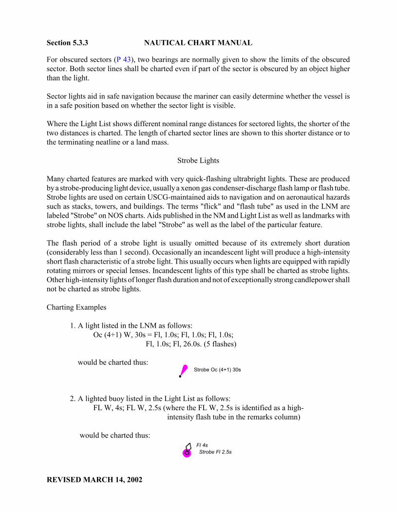
Charting Examples
1. A light listed in the LNM as follows:Oc (4+1) W, 30s = Fl, 1.0s; Fl, 1.0s; Fl, 1.0s;
Fl, 1.0s; Fl, 26.0s. (5 flashes)
would be charted thus: Strobe Oc (4+1) 30s
2. A lighted buoy listed in the Light List as follows: FL W, 4s; FL W, 2.5s (where the FL W, 2.5s is identified as a high-
intensity flash tube in the remarks column)
would be charted thus: Fl 4s
Strobe Fl 2.5s
angiew
UNITED STATES DEPARTMENT OF COMMERCE National Oceanic and Atmospheric Administration NATIONAL OCEAN SERVICE Office of Coast Survey
Silver Spring, Maryland 20910-3282
MARCH 14, 2002
MEMORANDUM FOR: All CartographersMarine Chart Division
FROM: Fannie B. PowersChief, Quality Assurance, Plans and Standards Branch
SUBJECT: Nautical Chart Manual: Correction Pages - Pages 5-15 and 5-16;Section Number Revision
Effective immediately, the following attachment replaces pages 5-15 and 5-16 in the Nautical ChartManual, Volume 1, Part 2, Seventh (1992) Edition.
The attachment:
1. Improves the legibility of the graphics on page 5-15,
2. Deletes the stack with strobe light graphic erroneously introduced during the NCM digitalconversion processes, as a graphic example of a strobe light used as a marker ( i.e., item 4.on page 5-15), and,
3. Revises the section number of Section 5.3 to Section 5.4.
Pages 5-15 and 5-16 are to be inserted into the Nautical Chart Manual, Volume 1, Part 2, Seventh(1992) Edition immediately after page 5-14.
Attachment

NAUTICAL CHART MANUAL Section 5.4
REVISED MARCH 14, 2002
3. A stack identified as a landmark with a strobe light would be charted thus:
STACK (STROBE, R LTS)
4. A strobe light used as a marker would be charted thus:
Marker (Strobe)
5.4 Buoys
A buoy is a floating object, other than a lightship, moored or anchored to the bottom as an aid tonavigation. Buoys may be classified according to:
Shape: spar, cylindrical or can, conical, nun, spherical, barrel, dan or pillar.
Color scheme: red, green, or checkered.
Topmark: fitted with a characteristic shape at the top to aid in its identification.
Sound: characteristic sound signal, may be further classified according to the manner in which the sound is produced, as a bell, gong, horn, trumpet, or whistle. buoy.
Light: buoy with a light having definite characteristics for detection and identification during darkness. If the light is produced by gas, it may be called a gas buoy.
Radiobeacon buoy: equipped with a marker radiobeacon
Sonobuoy: with equipment for automatically transmitting a radio signal when triggered by an underwater sound signal is called a sonobuoy.
Combination buoy: has more than one means of conveying intelligence; it may be called a lighted sound buoy if it is a lighted buoy provided with a sound signal.
Location: channel, mid-channel, middle ground, turning, fairway, bifurcation, junction, or sea buoy. A bar buoy marks the location of a bar. A buoy marking a hazard to
navigation may be classified according to the nature of the hazard, as obstruction, wreck, telegraph, cable, fish net, dredging, or spoil ground buoy.

Section 5.4 NAUTICAL CHART MANUAL
REVISED MARCH 14, 2002
Special Use: classified according to their use, as anchor, anchorage, quarantine, mooring, warping, swinging, marker, station, watch, or position buoy. A light-weight buoy especially designed to withstand strong currents is called a river buoy. An ice buoy is a sturdy one used to replace a more easily damaged buoy during a period when
heavy ice is anticipated.
IALA
The USCG has completed the conversion of U.S. Aids to Navigation to the International Association ofLighthouse Authorities (IALA) Maritime Buoyage System in both Region A and Region B. The IALA systemis followed by most of the world's maritime nations. The significant changes are these: black buoys shall begreen; black-and-white vertically striped buoys shall be red-and-white vertically striped buoys; and whitelateral lights shall be red or green, as appropriate. See also Section Q of Chart No. 1.
All navigable waters of the United States follow Region B, except U. S. possessions in the western PacificOcean west and south of a line extended in a southerly direction along the International Date Line to 10° Nlatitude, then easterly to 120° W longitude, which follow IALA Region A. Although there are differences inlateral aids to navigation between Region A and Region B, non-lateral aids to navigation are the same in bothRegions.
Lateral marks define the port and starboard sides of a route to be followed when proceeding in theconventional direction of buoyage. On entering a channel from seaward, buoys on the starboard (right) sideare green or black with even numbers in Region A and red with even numbers in Region B. Buoys on the port(left) side are red with odd numbers in Region A and green or black with odd numbers in Region B. Lightson red buoys may be red or white, while lights on green or black buoys may be green or white; however,white lights have been phased out of the lateral system. Safe Water buoys have red-and-white vertical stripes,are spherical or, in many instances, have a spherical topmark (see Chart No. 1, Q 11, Q d, Q e), and may bepassed on either side. Preferred Channel buoys have red-and-green horizontal bands, the top band colorindicating the preferred side of passage. Black may still be found in place of red on some safe water buoys,and in place of green on some preferred channel buoys.
Revision to charted aids shall be made on NOS charts from information published in the LNM, NM, LightList, and Canadian NM. Black buoys shall be changed to green and shall be depicted by an open buoy symbolwith Green 225 (50 percent, 120-LPI) fill and labeled "G"; red-and-black horizontally banded buoys shall bechanged to red-and-green and labeled "RG" or "GR" as appropriate (the top color indicating the preferred sideof passage and listed first on the label); the changing of black-and-white vertically striped buoys tored-and-white will also require a change in the accompanying label. On lighted or sound red-and-white buoysonly, a spherical topmark (see Chart No. 1, Q 11) may be added. The NM should be carefully examined forthe announcement of the addition of such topmarks.
angiew
angiew
angiew
angiew
angiew

UNITED STATES DEPARTMENT OF COMMERCE National Oceanic and Atmospheric Administration NATIONAL OCEAN SERVICE Office of Coast Survey
Silver Spring, Maryland 20910-3282
MARCH 14, 2002
MEMORANDUM FOR: All CartographersMarine Chart Division
FROM: Fannie B. PowersChief, Quality Assurance, Plans and Standards Branch
SUBJECT: Nautical Chart Manual: Page Header Number and Section NumberRevisions; Correction Pages - IALA Maritime Buoyage SystemNotes
Effective immediately, the following attachment replaces pages 5-17 and 5-18 in the Nautical ChartManual, Volume 1, Part 2, Seventh (1992) Edition.
The attachment:
1. Revises the page header numbers from Sections 5.3 and 5.3.1 to Sections 5.4 and 5.4.1respectively,
2. Revises Sections 5.3.1 and 5.3.2 to Sections 5.4.1 and 5.4.2 respectively, and,
3. Improves the legibility of the IALA Maritime Buoyage System Notes
Pages 5-17 and 5-18 are to be inserted into the Nautical Chart Manual, Volume 1, Part 2, Seventh(1992) Edition immediately after page 5-16.
Attachment

NAUTICAL CHART MANUAL Section 5.4
REVISED JANUARY 8, 2004
Charts in the process of conversion to the IALA Maritime Buoyage System shall carry one of thefollowing notes. After a chart has been converted, the note shall be removed.
The following note shall be added to all Region A charts going forward:
CAUTIONCHANGES IN BUOYAGE
Mariners are advised that authorized aids to navigation are being changed toconform to maritime standards of the International Association of LighthouseAuthorities Maritime Buoyage System, Region A. Significant changes are: blackor green port hand buoys to red with an even number, red starboard buoys togreen with an odd number; black and white vertically striped buoys to red andwhite vertically striped buoys; and lateral lights from white to red and green asappropriate. Changes to aids to navigation will be announced in the NationalGeospatial-Intelligence Agency weekly Notice to Mariners and the U.S. CoastGuard 14th District Local Notice to Mariners.
The following note shall be added to all Region B charts going forward:
CAUTIONCHANGES IN BUOYAGE
Mariners are advised that authorized aids to navigation are being changed toconform to maritime standards of the International Association of LighthouseAuthorities Maritime Buoyage System, Region B. Significant changes are: blackport hand buoys to green; black and white vertically striped buoys to red and whitevertically striped buoys; and lateral lights from white to red or green asappropriate. Changes to aids to navigation will be announced in the NationalGeospatial-Intelligence Agency weekly Notice to Mariners and the U.S. CoastGuard Local Notice to Mariners.
The notes shall be in magenta, 7 pt. Swiss Light, set 3 1/2" wide, and shall be outlined with an0.008" magenta border 1/8" from the text. The notes will preferably be placed in any prominentlocation in the top margin. If sufficient margin space is not available (as determined by examinationof a trimmed copy of the chart), the notes may be placed anywhere within the chart that will notrequire the deletion (and later replacement) of charted detail. The notes shall be removed when allnonconforming charted aids to navigation have been converted to the IALA system.
The Canadian Coast Guard (CCG) has completed the implementation of the IALA MaritimeBuoyage System in Canadian waters. All charted Canadian aids to navigation should be checkedfor IALA compliance.
5.4.1 Charting Practices
The position of a buoy is shown with a small circle, the "approximate position" symbol (Q 1),because of practical limitations in positioning and maintaining buoys and their sinkers in precisegeographic locations.
angiew

Section 5.4.1 NAUTICAL CHART MANUAL
REVISED MARCH 14, 2002
Channel buoy symbols should be shown at a 65� angle from the channel lines, with the symbolpointing toward the top of the chart whenever possible. They should be shown in their publishedposition on large-scale charts. A floating aid may be charted off position only on a small-scale chartwhere it marks the edge of a maintained channel which is charted larger than its true width (that is,one that is exaggerated in width to a minimum size). In this case, the floating aid shall be positionedon the charted channel limit line and not inside the channel. Where a buoy position would coincidewith the symbol for another critical feature, such as a rock awash, the buoy may be charted slightlyoff position, for clarity, but always on the same azimuth to the feature it marks.
Buoy symbols marking the limits of fish trap areas (Section 4.14.2) should be oriented so as to fallinside the area and, in general, at an angle of 65� from the limiting lines.
Except as noted above, the orientation of buoy symbols should be about 25� from the vertical withthe symbol inclined toward the label.
5.4.2 Buoy Characteristics
1. Charted Characteristics
The characteristics of buoys (their color and shape and the color and period of their light) should beshown on the digital chart files in the exact position they will occupy on the printed chart. Allcharacteristics shall be abbreviated as shown in Chart No. 1 (Q 2 - Q 71, and a - u) and the LightList. Buoy characteristics shall be shown in 7 pt. Swiss Regular Italic. Buoy numbers andcharacteristics should be shown clear of rock symbols, shoals, least depths, etc.
Shape and Fog Signal (Q 20 - 26 & a - e, R 10 - 16, R 20 - 22)
Buoys are identified on charts by their shape (can, nun, spherical buoy, spar buoy, or pillar buoy) andby any audible signal they emit (bell, whistle, gong).
Color (Q 2 - 6 & a - n)
All buoys except mooring buoys and black buoys should show their color characteristic using thespecified abbreviations. Red buoys are shown with magenta fill labeled "R", green buoys with greenfill and "G" label, and black buoys with black fill. The black section of multi-colored buoys islabeled "B". The color of mooring buoys is never shown.
Number (Q 3, Q f, Q g)
The identifying number (or letter) which is painted on the buoy should be shown in quotes, e.g.,"22".
angiew
angiew
angiew
angiew
angiew
angiew
angiew
angiew
angiew
angiew
angiew
angiew
angiew
angiew

UNITED STATES DEPARTMENT OF COMMERCE National Oceanic and Atmospheric Administration NATIONAL OCEAN SERVICE Office of Coast Survey
Silver Spring, Maryland 20910-3282
MAY 1, 2002
MEMORANDUM FOR: All CartographersMarine Chart Division
FROM: Fannie B. PowersChief, Quality Assurance, Plans and Standards Branch
SUBJECT: Nautical Chart Manual: Page Header Number and Section NumberRevisions; Correction Pages - Pages 5-19 through 5-22
Effective immediately, the following attachment replaces pages 5-19 through 5-22 in the NauticalChart Manual, Volume 1, Part 2, Seventh (1992) Edition.
The attachment:
1. Revises the page header numbers from Sections 5.3.2 and 5.3.3 to Sections 5.4.2 and 5.4.3,respectively.
2. Revises the section number of Section 5.3.3 to Section 5.4.3,
3. Improves the legibility of the Radar Reflectors Note and the Racing Buoys Note,
4. Improves the legibility of the order of characteristic omission examples, and
5. Revises the full name of the acronym: ODAS to the correct term: Ocean Data AcquisitionSystem
Pages 5-19 through 5-22 are to be inserted into the Nautical Chart Manual, Volume 1, Part 2,Seventh (1992) Edition immediately after page 5-18.
Attachment

NAUTICAL CHART MANUAL Section 5.4.2
REVISED MAY 1, 2002
Light Characteristics
Lighted buoys are charted with a magenta disc, 2.5 mm in diameter, centered on the circle at the baseof the buoy symbol (Q 7). The light is identified by its flash characteristics and color.
Example: "Fl R 4s"
The period (cycle) of lights on lighted buoys is expressed in seconds using the abbreviation "s".Periods shall be given to the nearest tenth of a second as reported by the source.
Privately Maintained Buoys (Q 70)
Private buoys listed in the Light List shall be identified with the label "Priv" in 7 pt. Swiss RegularItalic. The service name shall be charted on military aids, e.g., "Navy". On small-scale charts, orwhen space is limited, this information may be omitted if it is charted on one or more large-scalecharts covering the area. Privately maintained buoys not listed in the Light List generally are notcharted.
Radar Reflectors
A radar-enhancing structure or reflective material has been installed on nearly all major buoys andmany minor buoys. Reference to this radar reflector should not be charted as part of the buoys'characteristics, but the following note should be included on the chart:
RADAR REFLECTORS Radar reflectors have been placed on many
floating aids to navigation. Individual radar reflector identification on these aids has been omitted from this chart.
2. Order of Characteristics
On large-scale charts, the characteristics of buoys shall be shown in the following order:
1. Color of buoy (omit if black)2. Number (or letter)3. Flash character (if lighted)4. Light color (if lighted)5. Light period (if lighted)6. Fog signal
The complete legend would be charted as follows:
angiew
angiew

Section 5.4.2 NAUTICAL CHART MANUAL
REVISED MAY 1, 2002
Lighted buoy Unlighted buoy
R "22" R Fl R 4s BELL N "22"
3. Omission of Characteristics
In congested areas and on smaller-scale charts, omissions of buoy characteristics shall be made inthe following order:
Lighted Buoys Unlighted Buoys
1st, light period: 1st, color of buoy:
R "22" N "22" Fl R 4s BELL
2nd, color of buoy: 2nd, number:
Fl R "22" N BELL
3rd, number:
Fl R BELL
4th, light color and flash characteristic:
BELL
5.4.3 Types of Buoys
Cardinal Buoys
Cardinal buoys do not have a unique shape, but are normally pillars or spars. They are always paintedwith yellow and black horizontal bands, and their distinctive topmarks are always black. Lighted

NAUTICAL CHART MANUAL Section 5.4.3
REVISED MAY 1, 2002
cardinal buoys also have a special system of flashing white lights. The rhythms are "very quick" or"quick" flashing, but the flashing phase is broken into varying lengths. Variations in the lightcharacteristics, the order of the painted bands, and the arrangement of the topmarks all serve toidentify the area of navigable water relative to the buoy (see Chart No. 1, pages 74 [Q 130.3 - 130.6]and 98 [IALA Maritime Buoyage System - Cardinal Marks Regions A and B]).
The USCG will not use cardinal buoys in its modification of the IALA Buoyage System in theforeseeable future. However, since Canada uses cardinal buoys, the pictorial buoy symbols arerequired for Great Lakes metric charts.
Nautical charts of the east coast, west coast, and Great Lakes waters that use traditional (non-metric)units shall chart cardinal buoys with a horizontally banded buoy symbol (Q 4). No color will beshown within the buoy symbol, nor will topmark symbols be used. Metric charts of the Great Lakesshall show cardinal buoys with a horizontally banded pictorial buoy symbol along with the properarrangement of topmarks. See Q 130.3, page 74 of Chart No. 1 for further details concerning cardinalbuoys, called "cardinal marks" therein.
Mooring Buoys (Q 40, Q s, Q t)
A mooring buoy is a buoy established for the purpose of mooring a vessel, usually by means of aring fitted to the top of the buoy. For charting purposes, mooring buoys do not include superbuoys.
Small noncommercial, single-boat mooring buoys that are usually used for mooring pleasure craftand do not obstruct traffic or otherwise constitute a hazard to navigation shall not be charted.
Mooring buoys that are to be charted, whether they are lighted or unlighted cans, nuns, spars, or anyother shape, shall be shown by the mooring buoy symbol.
Mooring buoys are not generally included in the Light List, but they are charted when they arepublished in the NM or at the request of the establishing agency.
Pictorial Buoys
NOS uses the CHS pictorial buoy symbols on metric charts of the Great Lakes co- produced withCHS. CHS has recently redesigned these pictorial buoy symbols so that they are now available intwo sizes; the larger size is to be used except in congested areas. In addition, some of the buoysymbols are available with either a right-hand or a left-hand slope. The right-hand slope isconsidered the standard presentation However, either symbol may be rotated, if necessary, to clearchannels or adjacent charted detail. Port-side buoys retain a black fill despite the change of color ofbuoy itself from black to green. Starboard-side buoys retain a magenta fill. The other pictorial buoysymbols do not employ color fill. CHS also has introduced a new pillar buoy symbol for chartingall lighted buoys, except lighted spars and superbuoys, and all sound buoys whether lighted or not.The magenta fog-signal symbol of three concentric arcs (R 1) is no longer used.
angiew
angiew
angiew
angiew
angiew
angiew

Section 5.4.3 NAUTICAL CHART MANUAL
REVISED MAY 1, 2002
Preferred Channel Buoys (Q 4, Q h)
The USCG uses red-and-green horizontally banded buoys to aid in safe navigation at waterwayjunctions and to mark safe routes past hazardous obstructions. The color of the topmost band of apreferred channel buoy directs the mariner to the side of preferred passage. Thus, in IALA RegionB, green on the topmost band means the preferred channel is to starboard, while red on the topmostband means the preferred channel is to port. The colors would be reversed to mark the preferredchannel in IALA Region A. The correct descriptive label "RG" (when the topmost band is red) or"GR" (when the topmost band is green) shall be shown as part of the charted label. Black may stillbe found on some aids and shall continue to be charted as such until the change to green for that aidis announced by the establishing authority.
Racing Buoys
These buoys are not usually included in the Light List and should not be charted except by specialrequest. In certain areas where racing buoys are established, the following note shall be shown:
RACING BUOYS Racing buoys within the limits of this chart are not shown hereon. Information may be obtained from the U. S. Coast Guard District Offices as racing and other private buoys are not all listed in the U.S. Coast Guard Light List.
Safe Water Buoys (Q 11, Q 130.5, Q d, Q e)
The black-and-white vertically striped midchannel, fairway, or safe water buoys are being changedto red-and-white vertically striped buoys. These changes are announced in the LNM. The NM alsoannounces any additions of spherical topmarks on lighted or sound-equipped red and white verticallystriped buoys. See Q 11 for the symbol for a spherical topmark.
Superbuoys (P 8, Q 26, Q 58)
The term "superbuoy" usually refers to one of three principal types of buoys:
SPM's (single-point moorings) are large mooring buoys (or tanker terminal buoys) used tomoor tankers for offshore loading and unloading.
ODAS (Ocean Data Acquisition System) buoys are used for collecting oceanographic ormeteorological information.
LNB's (Large Navigation Buoys) or LANBY's (Large Automatic Navigation Buoys) areusually designed to take the place of lightships.
angiew
angiew
angiew
angiew
angiew
angiew
angiew
angiew

UNITED STATES DEPARTMENT OF COMMERCE National Oceanic and Atmospheric Administration NATIONAL OCEAN SERVICE Office of Coast Survey
Silver Spring, Maryland 20910-3282
APRIL 30, 2002
MEMORANDUM FOR: All CartographersMarine Chart Division
FROM: Fannie B. PowersChief, Quality Assurance, Plans and Standards Branch
SUBJECT: Nautical Chart Manual: Intracoastal Waterway Aids to NavigationParagraphs (and Note Examples) Removed from “Ranges”Section; Page Header Number and Section Number Revisions; Correction Pages - Pages 5-23 through 5-32
Effective immediately, the following attachment replaces pages 5-23 through 5-34 in the NauticalChart Manual, Volume 1, Part 2, Seventh (1992) Edition.
The attachment:
1. Removes the paragraphs explaining Intracoastal Waterway Aids to Navigation (and theassociated note examples) from “Ranges” section (Note: IWW Aids moved to Section 5.2per Cartographic Order 023/01),
2. Improves the legibility of the Articulated Aids Note,
3. Improves the legibility of all associated graphics.
4. Revises all section numbers and page header numbers as indicated.
Pages 5-23 though 5-34 are to be inserted into the Nautical Chart Manual, Volume 1, Part 2,Seventh (1992) Edition immediately after page 5-22.
Attachment

NAUTICAL CHART MANUAL Section 5.4.3
REVISED APRIL 30, 2002
These superbuoys vary in size from about 21 feet in diameter for some of the SPM's to 33 and 40feet in diameter for ODAS buoys and 40 feet in diameter for LNB's. Because their large size rendersthem an unusual hazard to navigation, these buoys shall be emphasized on nautical charts by the useof the appropriate superbuoy symbol.
Superbuoys are identified in the LNM by the following notations:
"LNB" on all items concerning LNB's"SPM" on all items concerning tanker terminal buoys"ODAS" on all items concerning anchored oceanographic buoys.
Any buoy identified with the acronym "ODAS" in the source material shall be charted as asuperbuoy, regardless of its size.
RY ODAS “46005" Fl (4) 20s PA
Non-circular buoys shall be charted as superbuoys if the largest dimension is greater than 16 feet.
The height and visibility of lights shall be charted for LNB's from USCG-supplied information.
Isolated Danger Buoys (Q 130.4, Q h)
These buoys will be erected on or moored above or near an isolated danger which has navigablewater all around. The buoy will be horizontally banded black and red with a topmark consisting oftwo black spheres mounted atop one another. If lighted, isolated danger buoys will exhibit a whitelight with a group flashing (two flashes) five second characteristic (FL (2) W 5s).
Example: BR Fl (2) 5s
Fish Aggregating Devices (FADS)
In Hawaii, fishery biologists have developed Fish Aggregating Devices (FADS) to attract fish forrecreational and commercial fishermen.
These are clusters of submerged hollow spheres tethered to 5-foot diameter spherical buoys, yellowin color, displaying a flashing amber light every 4 seconds. They are anchored to the bottom byheavy concrete blocks, and placed in depths of 480 to 9,000 feet at distances of 2 to 15 milesoffshore.
angiew
angiew
angiew
angiew
angiew

Section 5.5 NAUTICAL CHART MANUAL
REVISED APRIL 30, 2002
They shall be shown on charts of the Hawaiian Islands.
Example: Y
FAD “A” Fl Y 4s Priv
5.5 Fog Signals
Fog signals are audible aids used to warn of danger and to provide the mariner with a means ofdetermining a craft's position when visibility is obscured by fog, snow, rain, smoke, or thick weather.Among the devices in common use as fog signals are the following:
Diaphones produce sound by means of a slotted reciprocating piston actuated by compressedair. "Two-tone" blasts consist of two tones of different pitch, beginning with a high-pitchedblast and ending on a low pitch.
Diaphragm horns produce sound by means of a disc diaphragm vibrated by compressed airor electricity.
Sirens produce sound by means of either a disk or a cup-shaped rotor actuated by compressedair or electricity.
Whistles produce sound by compressed air emitted through a circumferential slot into acylindrical bell chamber.
Bells produce a distinctive sound by the vibration of a hollow, cup-shaped metallic vesselwhich gives forth a ringing sound when struck.
Gongs produce a sound by the vibration of a resonant disc excited by a blow.
Each fog signal has specific characteristics by which it can be distinguished (see section R of ChartNo. 1). The signal characteristic is the phase relationship of the recurring sound emissions. Fogsignals on fixed stations and large navigational buoys produce a specific number of blasts and silentperiods each minute, when operating, to provide positive identification. Fog signals on buoys aregenerally activated by the motion of the sea; therefore, they do not emit regular signal characteristicsand, when the sea is calm, may emit no sound signals.
Fog signals are labeled as "DIAPHONE", "HORN", "SIREN", "WHISTLE", "BELL" or GONG".The appropriate designation should be spelled out as part of the characteristic of the aid. Thecharacteristics of a grouped sound signal shall be charted using the same guidelines as for a groupedlight, e.g., HORN (3) 20s.
angiew

NAUTICAL CHART MANUAL Section 5.6
REVISED APRIL 30, 2002
5.6 Daybeacons
Daybeacons are unlighted fixed aids to navigation placed either on shore or in the water. Theyare established and maintained by the USCG and are identified on charts by their color andshape. Some daybeacons have reflective borders to enable navigators using a searchlight to morereadily locate them at night. These reflectors are the same color as the aids.
Daybeacons (Q 80 - 83, Q r)
Where daybeacons are charted, they shall be shown on the raster chart files in their true positionby the standard square or triangular symbol. The center of the daybeacon symbol is the aid'scorrect geographic position.
The standard symbol to depict triangularly shaped dayboards is a triangle 2.0 mm on each side.A 1.5-mm triangle may be used as an alternative. Non-triangular dayboards, i.e., square,rectangular, round, octagonal, or diamond-shaped dayboards, are all charted with the standardsquare daybeacon symbol. This is a square 1.65 mm on each side (or a smaller 1.3-mm square).
Examples:
The larger symbols should be used wherever possible. The smaller symbols are to be used onlyin very congested areas to improve symbol legibility by reducing overlap with other symbols anddetail and to avoid symbol displacement. The two sizes of symbols should not be used in closeproximity to one another.
Triangular daybeacons marking the starboard (right) side of a channel shall be shown with agreen fill in IALA Region A and a magenta fill in IALA Region B; triangular daybeacons of anyother color shall be shown as open triangles with colors and identifying numbers or lettersincluded in the label.
Square daybeacons marking the port (left) side of a channel shall be shown with magenta fillin IALA Region A and a green fill in IALA Region B. Square symbols for other colors ofdaybeacons will be shown as unfilled squares and labeled as to color and identifying numbersor letters.
Examples: W GR Bn Bn
angiew
angiew
angiew

Section 5.6 NAUTICAL CHART MANUAL
REVISED APRIL 30, 2002
The abbreviation "Bn" should be used only to depict beacons which do not have identifying numbersor letters. In congested areas, the legend "Bn" may be omitted, but the color designation should beretained. The color abbreviation shall be shown and placed above the identifying number, or aboveor after "Bn". Identifying numbers or letters are included in quotes.
Example: G Bn
A daybeacon's characteristics are shown in 7 pt. Swiss Regular type.
Private beacons listed in the Light List shall be charted and labeled "Priv" in 7 pt. Swiss Regulartype. On small-scale charts or when space is limited, this information may be omitted if charted onone or more large-scale charts covering the area. Privately maintained beacons not listed in the LightList generally are not charted. However, see also Section 5.6, Markers.
Articulated Daybeacons
An articulated daybeacon is structurally similar to an Articulated Light. Both consist of a verticalpipe structure that oscillates around a universal coupling connected to a sinker, and is kept uprightby the buoyancy of a submerged flotation chamber.
The introduction of this new type of aid to navigation requires a new chart symbol. Because of thestructural similarities to the articulated light and the oscillating characteristics, the 1.0 mm diameterapproximate position circle must be centered along the base of the fixed symbol representing thepublished position. The color fill for this new articulated daybeacon symbol shall be the same as thefill on the fixed daybeacon symbol; it shall not be broken for the 1.0 mm circle. The articulateddaybeacon shall be labeled "Art", caps and lower case Swiss Regular Italic type style. The formatfor charting characteristics shall be the same as for fixed daybeacons:
Art G Art R “5" “12"

NAUTICAL CHART MANUAL Section 5.6
REVISED APRIL 30, 2002
An explanatory note shall be placed on all charts with articulated aids. The note shall be in black 7pt. Swiss Light type, set 2" wide:
ARTICULATED AIDS An articulated aid to navigation consists of a pipe structure that oscillates around a universal coupling connected to a sinker. The structure is kept upright by the buoyancy of a submerged flotation chamber. It is designed primarily to mark narrow channels in depths of up to 60 feet. All articulated aids are labelled “Art”.
5.7 Markers
The term "marker" generally refers to any private fixed aid to navigation (lighted or unlighted)erected to mark minor channels. Such markers are not established or maintained by the USCG andare not listed in the Light List.
The term may also refer to markers having other specific purposes, e.g., measured mile marks ordredging range markers.
A marker's purpose, status, position, date of establishment, the agency or person who established it,and whether the aid is maintained should be determined before a marker is charted.
The position of recently established markers should be confirmed by NOS field parties, but they maybe charted during the interim without this confirmation if the source is deemed valid.
Markers (B 32, B 33, P 3, Q 101)
Markers established and maintained either privately or by State or local governments shall be chartedwith the accurate landmark symbol and the label "MARKER", if the position meets third-ordertriangulation standards (within 10 feet of its true location or reported to 0.1 second).
A marker that does not meet these accuracy standards may be charted with the "positionapproximate" symbol and label "Marker".
Example: Marker
The label "(lighted)" shall be added if the marker is lighted (P 3).
angiew
angiew
angiew
angiew
Section 5.8 NAUTICAL CHART MANUAL
REVISED APRIL 30, 2002
5.8 Ranges
When two or more objects appear directly in line, one behind the other, they are said to be "in range."When two or more aligned objects are charted, they constitute a range which can provide marinerswith a very accurate and easily obtained line of position. Ranges are so useful in marking a coursethat artificial ranges, usually in the form of two lights mounted on daymarks, have been installed inline with channels in many ports. Most ranges are aligned with the center of the channel, but in someareas more than one range may be charted to define the inbound and outbound ranges of the channel.Only ranges published in the Light List shall be charted.
The line defined by the range is called a "range line" or "leading line." Daybeacons and other chartedobjects forming a range are often called "leading marks." Range lights are often called "leadinglights."
Range Lines (M 1)
The usable portion of ranges shall be shown by a solid line to the point where the vessel should leavethe range. From that point, the range shall be continued with a short-dashed line to the rearnavigational aid. Names of ranges may be charted if they are published in the Light List. Bearingsof ranges may be charted if they are published in the Light List and are considered useful to themariner.
In the event of extreme shoaling or shoaling over a large area in an improved channel, range linesmay be dashed or even omitted through a shoaling area that is depicted by hydrography.
Range Lights (P 20.1)
Range lights, or leading lights, are pairs of lights forming a range to mark a preferred channel orentrance to a harbor. The rear light is higher than the front light and a considerable distance behindit; the mariner uses the range by keeping the lights in line as the vessel progresses along the channel.High-intensity range lights are sometimes used to aid in daylight navigation. Otherwise, the rangelight structures are equipped with dayboards for daytime use.
Range lights may be of any standard light color or period, the principal requirement being that theystand out from their surroundings. Most range lights show a high-intensity beam within only a verynarrow arc of visibility marking the channel centerline and are obscured around the remainder of thehorizon. Most range lights appear to lose brilliance rapidly or become totally obscured as a shipdiverges from the range line. Range-marking lights are often visible miles beyond the length of thechannel they are marking. This strong beam is necessary to ensure visibility in even the most adverseweather conditions. The visibility range of range lights shall not be charted.
angiew
angiew
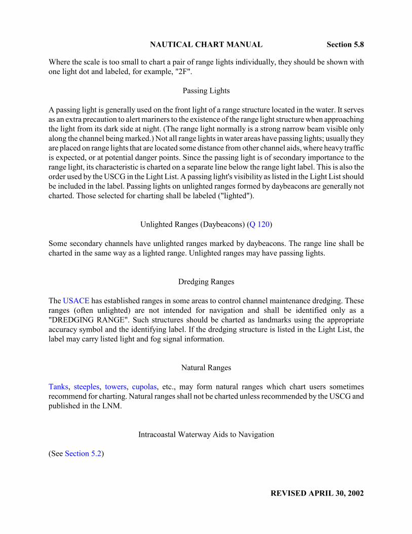
NAUTICAL CHART MANUAL Section 5.8
REVISED APRIL 30, 2002
Where the scale is too small to chart a pair of range lights individually, they should be shown withone light dot and labeled, for example, "2F".
Passing Lights
A passing light is generally used on the front light of a range structure located in the water. It servesas an extra precaution to alert mariners to the existence of the range light structure when approachingthe light from its dark side at night. (The range light normally is a strong narrow beam visible onlyalong the channel being marked.) Not all range lights in water areas have passing lights; usually theyare placed on range lights that are located some distance from other channel aids, where heavy trafficis expected, or at potential danger points. Since the passing light is of secondary importance to therange light, its characteristic is charted on a separate line below the range light label. This is also theorder used by the USCG in the Light List. A passing light's visibility as listed in the Light List shouldbe included in the label. Passing lights on unlighted ranges formed by daybeacons are generally notcharted. Those selected for charting shall be labeled ("lighted").
Unlighted Ranges (Daybeacons) (Q 120)
Some secondary channels have unlighted ranges marked by daybeacons. The range line shall becharted in the same way as a lighted range. Unlighted ranges may have passing lights.
Dredging Ranges
The USACE has established ranges in some areas to control channel maintenance dredging. Theseranges (often unlighted) are not intended for navigation and shall be identified only as a"DREDGING RANGE". Such structures should be charted as landmarks using the appropriateaccuracy symbol and the identifying label. If the dredging structure is listed in the Light List, thelabel may carry listed light and fog signal information.
Natural Ranges
Tanks, steeples, towers, cupolas, etc., may form natural ranges which chart users sometimesrecommend for charting. Natural ranges shall not be charted unless recommended by the USCG andpublished in the LNM.
Intracoastal Waterway Aids to Navigation
(See Section 5.2)
angiew
angiew
angiew
angiew
angiew
angiew
angiew

Section 5.9 NAUTICAL CHART MANUAL
REVISED APRIL 30, 2002
5.9 Courses
Courses, also called tracks, are a long-established feature on some nautical charts. They are usuallyestablished in rivers, bays, and other inshore waters and are used primarily to help mariners avoidshoal depths rather than to regulate shipping movement. The use of courses is generally left to thediscretion of the mariner and will depend on the vessel's draft, the state of the water level, adequacyof navigational aids, etc. Charted courses shall not be repositioned on a chart unless recommendedby the agency which has jurisdiction for establishing that particular course. When safe passage alongcertain parts of a course is questionable due to changing conditions, those sections shall be deletedfrom the chart. Courses may be part of general routing systems (see Section 5.10).
Bearings charted along courses must be true and not magnetic and shall be charted in degrees andtenths of a degree. However, quarters of degrees listed in the Light List shall be charted as given.Bearings measured from the chart must agree with bearings stated on the chart, in the Light List, andin Coast Pilots. Bearings charted along two-way courses must be reciprocal.
Distances along courses, if charted, may be in statute miles or nautical miles depending on therecommendation and the data submitted by the authorizing agency. Charted distances shall be givenin miles and tenths of a mile. A 1/4 mile distance shall be charted as 0.2 mile and a 3/4 mile distanceshall be charted as 0.7 mile.
Mileage ticks along courses have been charted in some areas and are usually furnished by theauthorizing agency. Mileage ticks are generally charted in statute miles at either 1-mile or 5-mileintervals, depending on the scale of the chart. Other subdivisions of benefit to the chart user may alsobe charted. The distance between mileage ticks should be at least 5 cm but not greater than 25 cm.At scales larger than 1:30,000, 1-mile intervals should be used. At smaller scales, 5-mile intervalsshould be used. Mileage ticks shall be in magenta, 2 cm in length, 0.2-mm lineweight, perpendicularto and centered on the recommended course. The mileage designation shall be in 7 pt. Swiss RegularItalic and charted in this format "St M 125". The mileage label should be placed along the tick, butmay be moved perpendicular to the recommended course to clear charted detail. Mileage ticks andlabels shall be deleted when accompanying sections of recommended courses are deleted as theresult of changing conditions.
For charts that show mileage ticks only, the orientation of the ticks shall be along the natural channeland shall follow the guidelines stated in the previous paragraph.
A magenta dot shall not be charted at the intersection of the mileage tick and the recommendedcourse or to indicate the location of a natural channel where the mileage tick only is charted.
5.9.1 Recommended and Alternate Courses
Recommended Courses Marked by Aids (M 3)
Recommended courses marked by fixed or floating aids shall be charted with an 0.2-mm solidmagenta line based on data furnished by the agency that has jurisdiction for establishing the course
angiew
angiew
angiew

NAUTICAL CHART MANUAL Section 5.9.1
REVISED APRIL 30, 2002
(M 3 Supplementary National Symbol). Traffic-flow directional arrows may be inserted at regularintervals along the line, if recommended. A two-way course should have opposing pairs of arrowsinserted at regular intervals.
Recommended Courses Not Marked by Aids (M 4)
Recommended courses that are not marked by fixed or floating aids shall be charted with an 0.2-mmdashed magenta line, again based on data furnished by the agency that has jurisdiction forestablishing the courses. The dash length shall be 2.0-mm with an 0.75-mm space between dashes.The same criteria for adding arrows to indicate the direction of traffic flow apply as for coursesmarked with aids.
Alternate Courses (M c)
An alternate course is a secondary course available to shallower draft vessels. Usually an alternatecourse will rejoin the recommended course.
An alternate course shall be charted with a dashed magenta line whether or not it is marked by aidsto navigation. Arrows should be used to indicate the direction of traffic flow if so recommended.
5.9.2 Trial Courses (Q 122)
A trial course is a course at sea, the ends of which are marked by ranges ashore and the length ofwhich has been accurately measured. Trial courses are used by vessels to calibrate logs, enginerevolution counters, etc., and to determine speed. Reciprocal bearings shall be charted.
Standard landmark symbols shall be used to mark the ranges ashore. When the measured distanceis within 6 feet of the standard value for a nautical mile (1,852 meters or 6,076.1 feet), a trial shallbe charted as shown in figure below.
MARKERS MARKERS
MEASURED NAUTICAL MILE
COURSE 150°00' - 330°00' TRUE
angiew
angiew
angiew
angiew
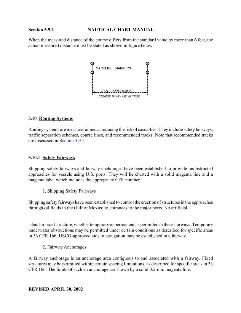
Section 5.9.2 NAUTICAL CHART MANUAL
REVISED APRIL 30, 2002
When the measured distance of the course differs from the standard value by more than 6 feet, theactual measured distance must be stated as shown in figure below.
MARKERS MARKERS
TRIAL COURSE 6065 FT
COURSE 18°49' - 198°49' TRUE
5.10 Routing Systems
Routing systems are measures aimed at reducing the risk of casualties. They include safety fairways,traffic separation schemes, course lines, and recommended tracks. Note that recommended tracksare discussed in Section 5.9.1.
5.10.1 Safety Fairways
Shipping safety fairways and fairway anchorages have been established to provide unobstructedapproaches for vessels using U.S. ports. They will be charted with a solid magenta line and amagenta label which includes the appropriate CFR number.
1. Shipping Safety Fairways
Shipping safety fairways have been established to control the erection of structures in the approachesthrough oil fields in the Gulf of Mexico to entrances to the major ports. No artificial
island or fixed structure, whether temporary or permanent, is permitted in these fairways. Temporaryunderwater obstructions may be permitted under certain conditions as described for specific areasin 33 CFR 166. USCG-approved aids to navigation may be established in a fairway.
2. Fairway Anchorages
A fairway anchorage is an anchorage area contiguous to and associated with a fairway. Fixedstructures may be permitted within certain spacing limitations, as described for specific areas in 33CFR 166. The limits of such an anchorage are shown by a solid 0.5-mm magenta line.
angiew

UNITED STATES DEPARTMENT OF COMMERCE National Oceanic and Atmospheric Administration NATIONAL OCEAN SERVICE Office of Coast Survey
Silver Spring, Maryland 20910-3282
MAY 1, 2002
MEMORANDUM FOR: All CartographersMarine Chart Division
FROM: Fannie B. PowersChief, Quality Assurance, Plans and Standards Branch
SUBJECT: Nautical Chart Manual: Page Header Number and Section NumberRevisions; Correction Pages - Pages 5-33 through 5-40
Effective immediately, the following attachment replaces pages 5-35 through 5-41 in the NauticalChart Manual, Volume 1, Part 2, Seventh (1992) Edition.
The attachment:
1. Improves the legibility of all Vessel Traffic Services (VTS) notes, and
2. Revises section numbers 5.9.2 and 5.9.2.1 to 5.10.2 and 5.10.2.1, respectively, and
3. Revises all page header numbers accordingly.
Pages 5-33 though 5-40 are to be inserted into the Nautical Chart Manual, Volume 1, Part 2,Seventh (1992) Edition immediately after page 5-32 (provided in Memorandum dated April 30,2002).
Attachment

NAUTICAL CHART MANUAL Section 5.10.2
REVISED MAY 1, 2002
5.10.2 Traffic Schemes
The USCG is responsible for the design and development of routing systems under guidelinesestablished by the IMO. Routing schemes adopted for international use by the IMO are publishedin Ships' Routing along with a description, geographic positions, and a map. A copy of Ships'Routing with current amendments is maintained in MCD.
The purpose of routing systems is to improve the safety of navigation in converging areas and inareas where the density of traffic is great or where the freedom of movement of shipping is inhibitedby restricted sea room, the existence of obstructions to navigation, limited depths, or unfavorablemeteorological conditions. The precise objective of any routing system will depend upon theparticular hazardous circumstances which it is intended to alleviate. All traffic schemes describedbelow shall be charted in magenta with magenta labels and notes.
5.10.2.1 Vessel Traffic Service Areas
Vessel Traffic Services (VTS), operated by the United States Coast Guard, enhances navigation,vessel safety, and environmental protection, and promotes safe vessel movement by reducing thepotential for collisions, rammings, and groundings, and the loss of life and property associated withthese incidents.
VTS provides the mariner with information related to safe navigation. This information coupled withthe mariner’s compliance with the provisions set forth in 33 CFR, Part 161, Vessel TrafficManagement, enhances the safe routing of vessels through congested and hazardous seaways. Someof the information provided covers hazardous conditions, traffic density, aids to navigation status,anticipated vessel encounters, anchorage availability, temporary measures, and harbor operations.
The Marine Chart Division is responsible for identifying, labeling, and referencing VTS informationon its nautical products.
CHART PORTRAYAL: VTS notes and labels will be included on all affected charts as neweditions are printed. When appropriate, a Notice to Mariners will be issued.
BOUNDARIES AND GEOGRAPHIC AREAS. VTS boundaries are not recommended. Instead,VTS labels are judiciously located within VTS areas on the nautical chart. 33 CFR, 161.25 through161.60 should be consulted for location of these areas. VTS Special Areas can be defined with amagenta dashed line: 0.2/2.0/0.75mm. Only the VTS Special Area labels should reference the CFRSection number.
MONITORING AREAS are not charted. Radio frequencies or call signs are not referenced exceptas written in VTS notes for San Francisco and Puget Sound.
angiew

Section 5.10.2.1 NAUTICAL CHART MANUAL
REVISED MAY 1, 2002
All Radio REPORTING POINTS (Calling-in Points) showing direction(s) of vessel movementwith designation shall be charted. Charts displaying the reporting points shall include a "call-inpoint" note. See Section 5.10.2.2, Traffic Separation Schemes, Calling-in Points for example notes.
Individual references to VTS CFR sections should not be charted in Precautionary Areas, TrafficSeparation Schemes, and VTS labels. Individual references to VTS CFR sections should be chartedin VTS Special Areas.
Notes and labels shall be magenta. Notes shall be 7 point Swiss Light and set 2 ½" wide. Labelsshould be Swiss Regular Italic, 7-10 points.
PUGET SOUND VTS NOTES
On Charts approaching the Strait of Juan de Fuca, 531, 18003, 18007, 18400, 18460, 18480, 18485,add:
NOTE _ The U.S. Coast Guard operates a mandatory Vessel TrafficServices (VTS) system in this area (Call Sign Seattle Traffic).The western boundary for VTS Puget Sound area is at48° 23' 08"N, 124° 43' 37"W to 48° 23' 30"N, 124° 44 ' 12"W,then due west to the territorial sea boundary, thence north- ward to its intersection with the United States / Canadian International Boundary line. Vessel operating procedures and designated radiotelephone frequencies are published in 33 CFR 161, the U.S. Coast Pilot, and/or the VTS User’s Manual.
On charts with both U.S. and Canadian waters, 18421, 18423, 18431, 18432, 18433, 18465, add:
NOTE _ The U.S. Coast Guard operates a mandatory Vessel TrafficServices (VTS) system in the U. S. waters covered by thischart. Vessel operating procedures and designated radio-telephone frequencies are published in 33 CFR 161, theU.S. Coast Pilot, and/or the VTS User’s Manual.
On charts approaching Strait of Juan De Fuca and with both US and Canadian waters, 18400, 18421,18423, 18431, 18432, 18433, 18460, 18465, 18480, 18485, add:
NOTE _ A Cooperative Vessel Traffic Services (CVTS) systemhas been established by the United States and Canadawithin the adjoining waters in the Juan de Fuca Region.The appropriate Vessel Traffic Center (VTC) (Tofino Traffic,Seattle Traffic, Vancouver Traffic) administers the rulesissued by both nations, however, it will enforce only itsown set of rules within its jurisdiction.
Add label:COOPERATIVE VESSEL TRAFFIC SERVICES
(see note _ )

NAUTICAL CHART MANUAL Section 5.10.2.1
REVISED MAY 1, 2002
On charts with US waters exclusively 18424, 18427, 18428, 18429, 18430, 18434, 18441, 18443,18444, 18445, 18446, 18447, 18448, 18449, 18450, 18452, 18453, 18456, 18457, 18458, 18464,18468, 18471, 18473, 18474, 18476, 18477, 18484, add:
NOTE _ The U.S. Coast Guard operates a mandatory Vessel TrafficServices (VTS) system in the Puget Sound area. Vessel operating procedures and designated radiotelephonefrequencies are published in 33 CFR 161, the U.S. CoastPilot, and/or the VTS User’s Manual. The entire area ofthe chart falls within the Vessel Traffic Services (VTS)system.
Add label to all affected charts.
PUGET SOUNDVESSEL TRAFFIC SERVICES AREA
(see note _ )
Add Special Area labels to charts 18400, 18421, 18423, 18427, 18429, 18430, 18431.
ROSARIO STRAIT GUEMES CHANNEL VTS Special Area: 161.55 (c) VTS Special Area: 161.55 (c)
(see note _ ) (see note _ )
PRINCE WILLIAM SOUND VTS NOTES
Charts partly covered by VTS, 16709, 16700, add:
NOTE _ The U.S. Coast Guard operates a mandatory Vessel TrafficServices (VTS) system in Prince William Sound. Vessel operating procedures and designated radiotelephonefrequencies are published in 33 CFR 161, the U.S. CoastPilot, and/or the VTS User’s Manual. Mariners shouldconsult these sources for applicable rules and reportingrequirements. Although mandatory VTS participation islimited to the navigable waters of the United States, certainvessels are encouraged or may be required, as a conditionof port entry, to report beyond this area to facilitate trafficmanagement within the VTS area.
Charts completely covered by VTS, 16707, 16708, add:
NOTE _ The U.S. Coast Guard operates a mandatory Vessel TrafficServices (VTS) system in Prince William Sound. Vessel operating procedures and designated radiotelephonefrequencies are published in 33 CFR 161, the U.S. CoastPilot, and/or the VTS User’s Manual. The entire area ofthe chart falls within the Vessel Traffic Services (VTS) system.
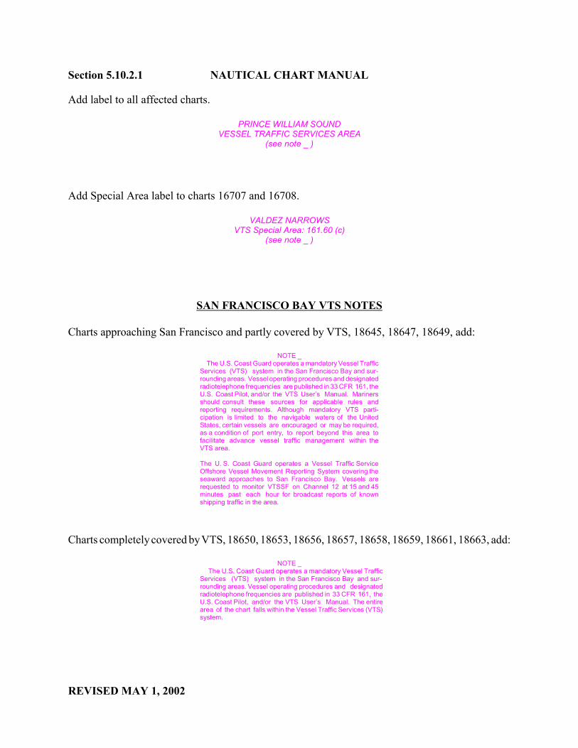
Section 5.10.2.1 NAUTICAL CHART MANUAL
REVISED MAY 1, 2002
Add label to all affected charts.
PRINCE WILLIAM SOUNDVESSEL TRAFFIC SERVICES AREA
(see note _ )
Add Special Area label to charts 16707 and 16708.
VALDEZ NARROWS VTS Special Area: 161.60 (c)
(see note _ )
SAN FRANCISCO BAY VTS NOTES
Charts approaching San Francisco and partly covered by VTS, 18645, 18647, 18649, add:
NOTE _ The U.S. Coast Guard operates a mandatory Vessel TrafficServices (VTS) system in the San Francisco Bay and sur-rounding areas. Vessel operating procedures and designatedradiotelephone frequencies are published in 33 CFR 161, theU.S. Coast Pilot, and/or the VTS User’s Manual. Marinersshould consult these sources for applicable rules andreporting requirements. Although mandatory VTS parti-cipation is limited to the navigable waters of the UnitedStates, certain vessels are encouraged or may be required,as a condition of port entry, to report beyond this area tofacilitate advance vessel traffic management within theVTS area.
The U. S. Coast Guard operates a Vessel Traffic ServiceOffshore Vessel Movement Reporting System covering theseaward approaches to San Francisco Bay. Vessels arerequested to monitor VTSSF on Channel 12 at 15 and 45minutes past each hour for broadcast reports of knownshipping traffic in the area.
Charts completely covered by VTS, 18650, 18653, 18656, 18657, 18658, 18659, 18661, 18663, add:
NOTE _ The U.S. Coast Guard operates a mandatory Vessel TrafficServices (VTS) system in the San Francisco Bay and sur-rounding areas. Vessel operating procedures and designatedradiotelephone frequencies are published in 33 CFR 161, theU.S. Coast Pilot, and/or the VTS User’s Manual. The entirearea of the chart falls within the Vessel Traffic Services (VTS)system.
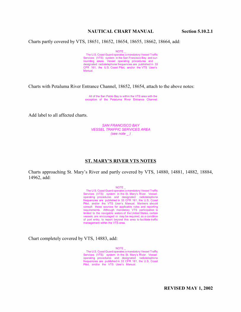
NAUTICAL CHART MANUAL Section 5.10.2.1
REVISED MAY 1, 2002
Charts partly covered by VTS, 18651, 18652, 18654, 18655, 18662, 18664, add:
NOTE _ The U.S. Coast Guard operates a mandatory Vessel TrafficServices (VTS) system in the San Francisco Bay and sur-rounding areas. Vessel operating procedures and designated radiotelephone frequencies are published in 33CFR 161, the U.S. Coast Pilot, and/or the VTS User’s Manual.
Charts with Petaluma River Entrance Channel, 18652, 18654, attach to the above notes:
All of the San Pablo Bay is within the VTS area with theexception of the Petaluma River Entrance Channel.
Add label to all affected charts.
SAN FRANCISCO BAYVESSEL TRAFFIC SERVICES AREA
(see note _ )
ST. MARY’S RIVER VTS NOTES
Charts approaching St. Mary’s River and partly covered by VTS, 14880, 14881, 14882, 18884,14962, add:
NOTE _ The U.S. Coast Guard operates a mandatory Vessel TrafficServices (VTS) system in the St. Mary’s River. Vessel operating procedures and designated radiotelephonefrequencies are published in 33 CFR 161, the U.S. CoastPilot, and/or the VTS User’s Manual. Mariners shouldconsult these sources for applicable rules and reportingrequirements. Although mandatory VTS participation islimited to the navigable waters of the United States, certainvessels are encouraged or may be required, as a conditionof port entry, to report beyond this area to facilitate trafficmanagement within the VTS area.
Chart completely covered by VTS, 14883, add:
NOTE _ The U.S. Coast Guard operates a mandatory Vessel TrafficServices (VTS) system in the St. Mary’s River. Vessel operating procedures and designated radiotelephonefrequencies are published in 33 CFR 161, the U.S. CoastPilot, and/or the VTS User’s Manual.

Section 5.10.2.1 NAUTICAL CHART MANUAL
REVISED MAY 1, 2002
Add label to all affected charts.
ST. MARY’S RIVERVESSEL TRAFFIC SERVICES AREA
(see note _ )
HOUSTON/GALVESTON VTS NOTES
Charts approaching Houston/Galveston waterways and partly covered by VTS, 11323, 11324, 11330,11340, 11300, add:
NOTE _ The U. S. Coast Guard operates a mandatory VesselTraffic Services (VTS) system in the Houston andGalvestonwaterways. Vessel operating procedures and designatedradiotelephone frequencies are published in 33 CFR 161,the U.S. Coast Pilot, and/or the VTS User’s Manual. Mariners should consult these sources for applicable rulesand reporting requirements. Although mandatory VTS parti-cipation is limited to the navigable waters of the UnitedStates, certain vessels are encouraged or may be required,as a condition of port entry, to report beyond this area tofacilitate advance vessel traffic management within theVTS area.
Charts completely covered by VTS, 11322A, 11326A, 11327, 11328, 11329A, B, add:
NOTE _ The U.S. Coast Guard operates a mandatory VesselTraffic Services (VTS) system in the Houston andGalvestonwaterways. Vessel operating procedures and designatedradiotelephone frequencies are published in 33 CFR 161,the U.S. Coast Pilot, and/or the VTS User’s Manual.
Add label to all affected charts.
HOUSTON / GALVESTONVESSEL TRAFFIC SERVICES AREA
(see note _ )

NAUTICAL CHART MANUAL Section 5.10.2.1
REVISED MAY 1, 2002
BERWICK BAY VTS NOTES
Charts approaching Berwick Bay and partly covered by VTS, 11351, 11352, 11354, 11355, add:
NOTE _ The U.S. Coast Guard operates a mandatory Vessel TrafficServices (VTS) system in Berwick Bay waterways.. Vessel operating procedures and designated radiotelephonefrequencies are published in 33 CFR 161, the U.S. CoastPilot, and/or the VTS User’s Manual. Mariners shouldconsult these sources for applicable rules and reportingrequirements. Although mandatory VTS participation islimited to the navigable waters of the United States, certainvessels are encouraged or may be required, as a conditionof port entry, to report beyond this area to facilitate trafficmanagement within the VTS area.
Add label to all affected charts.
BERWICK BAYVESSEL TRAFFIC SERVICES AREA
(see note _ )
Add Special Area label to charts 11354, 11355.
BERWICK BAY VTS Special Area: 161.40 (b)
(see note _ )
NEW YORK BAY VTS NOTES
Charts partly covered by VTS, 11350, 12324A, 12326, 12327, 12331, 12335, 12337, 12401, 12402,add:
NOTE _ The U.S. Coast Guard operates a mandatory Vessel TrafficServices (VTS) system in the New York Bay and sur-rounding areas. Vessel ope rating procedures and designatedradiotelephone frequencies are published in 33 CFR 161,the U.S. Coast Pilot, and/or the VTS User’s Manual. Mariners should consult these sources for applicable rulesand reporting requirements. Although mandatory VTS parti-cipation is limited to the navigable waters of the UnitedStates, certain vessels are encouraged or may be required,as a condition of port entry, to report beyond this area tofacilitate vessel traffic management within the VTS area.
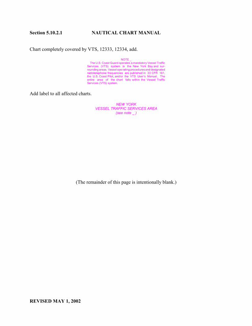
Section 5.10.2.1 NAUTICAL CHART MANUAL
REVISED MAY 1, 2002
Chart completely covered by VTS, 12333, 12334, add.
NOTE _ The U.S. Coast Guard operates a mandatory Vessel TrafficServices (VTS) system in the New York Bay and sur-rounding areas. Vessel ope rating procedures and designatedradiotelephone frequencies are published in 33 CFR 161,the U.S. Coast Pilot, and/or the VTS User’s Manual. Theentire area of the chart falls within the Vessel TrafficServices (VTS) system.
Add label to all affected charts.
NEW YORKVESSEL TRAFFIC SERVICES AREA
(see note _ )
(The remainder of this page is intentionally blank.)

NauticalChart
ManualVolume
NauticalChart
ManualPage
Illegible Item/Error Introduced during Digital Conversion
1 5-42 Quality of Traffic Lane Example Distorted
5-43 Quality of Sailing Directions Note Example Distorted
5-44 Quality of Calling-in Points Graphics Distorted
5-44 VTS Note (containing numeric and alphabetic designators):
-- vital information concerning voluntary calling-in points is missing
-- erroneous information provided for mandatory calling- in points.
UNITED STATES DEPARTMENT OF COMMERCE National Oceanic and Atmospheric Administration NATIONAL OCEAN SERVICE Office of Coast Survey
Silver Spring, Maryland 20910-3282
MAY 2, 2002
MEMORANDUM FOR: All CartographersMarine Chart Division
FROM: Fannie B. PowersChief, Quality Assurance, Plans and Standards Branch
SUBJECT: Nautical Chart Manual: Page Header Number and Section NumberRevisions; Correction Pages - Pages 5-41 through 5-44
Effective immediately, the following attachment replaces pages 5-42 through 5-44 in the NauticalChart Manual, Volume 1, Part 2, Seventh (1992) Edition.
The attachment revises section 5.9.2.2 to Section 5.10.2.2 and serves to correct the followingillegible items and cartographic error introduced to the Nautical Chart Manual during its conversionto digital format:
Pages 5-41 though 5-44 are to be inserted into the Nautical Chart Manual, Volume 1, Part I, Seventh(1992) Edition immediately after page 5-40 (provided in Memorandum dated May 1, 2002).
Attachment
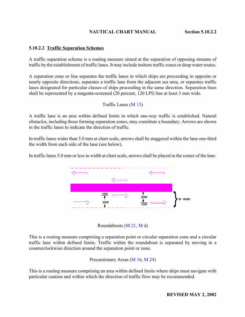
NAUTICAL CHART MANUAL Section 5.10.2.2
REVISED MAY 2, 2002
5.10.2.2 Traffic Separation Schemes
A traffic separation scheme is a routing measure aimed at the separation of opposing streams oftraffic by the establishment of traffic lanes. It may include inshore traffic zones or deep water routes.
A separation zone or line separates the traffic lanes in which ships are proceeding in opposite ornearly opposite directions, separates a traffic lane from the adjacent sea area, or separates trafficlanes designated for particular classes of ships proceeding in the same direction. Separation linesshall be represented by a magenta-screened (20 percent, 120 LPI) line at least 3 mm wide.
Traffic Lanes (M 13)
A traffic lane is an area within defined limits in which one-way traffic is established. Naturalobstacles, including those forming separation zones, may constitute a boundary. Arrows are shownin the traffic lanes to indicate the direction of traffic.
In traffic lanes wider than 5.0 mm at chart scale, arrows shall be staggered within the lane one-thirdthe width from each side of the lane (see below).
In traffic lanes 5.0 mm or less in width at chart scale, arrows shall be placed in the center of the lane.
Roundabouts (M 21, M d)
This is a routing measure comprising a separation point or circular separation zone and a circulartraffic lane within defined limits. Traffic within the roundabout is separated by moving in acounterclockwise direction around the separation point or zone.
Precautionary Areas (M 16, M 24)
This is a routing measure comprising an area within defined limits where ships must navigate withparticular caution and within which the direction of traffic flow may be recommended.
angiew
angiew
angiew
angiew
angiew

Section 5.10.2.2 NAUTICAL CHART MANUAL
REVISED MAY 2, 2002
Areas to Be Avoided (M 29)
These are areas which are not recommended for navigation because of shoal hydrography,obstructions, or local and Federal regulations.
Pilot Boarding Areas
Pilot boarding areas represent meeting or boarding places where vessels pick up or disembark pilots.A pilot vessel may either cruise in the area continuously or may be on call. The limits of pilot areasare usually charted with a 2.5-mm magenta-screened (20 percent, 120-LPI) band. The outside edgeof the band must coincide with the 5.9.2 limiting positions published for the area. These areas shallbe labeled as recommended by the authorized source. The legend "Pilot Boarding Area" is preferredif a labeling recommendation is not clear.
Alternatively, pilot areas may be shown only by the magenta symbol T 1.1 if the chart scale is toosmall to clearly show the area band or if only a single position location is authorized. The chartingof pilot stations was described in Section 3.9, Miscellaneous Stations.
Course Lines
Some Great Lakes charts show course lines that are an unofficial traffic separation scheme devisedby shipping interests for their own benefit. These course lines were not established by the USCG norare the regulations published in the CFR.
The course lines are charted with a black dashed line on traditional charts and a magenta dashed lineon metric charts. In either case, the labels for the course lines shall be magenta. The labels shallinclude distance (in statute miles and nautical miles) and bearings along the course. The point wherea course changes direction is shown with a black dashed line to a point of land or object ashore. Thebearing of the line and the distance offshore of the turning point are included in a black label alongthe dashed line.
The following sailing directions note shall be included on Great Lakes metric charts with Mercatorprojections that include course lines:
SAILING DIRECTIONS. Bearings of sailing courses are true and distancesgiven thereon are in statute miles (St M) and nautical miles (NM) between points of departure. The true bearing between any two points on thischart may be determined by connecting the two points with a straightline and measuring the angle of its intersection with a meridian line.
This note shall be in black, 7 pt. Swiss Light type, set 3½" wide. This note shall be included in thegroup of notes aligned under the chart title.
angiew
angiew
angiew

NAUTICAL CHART MANUAL Section 5.10.2.2
REVISED MAY 2, 2002
Calling-in Points (M 40)
Calling-in Points, requiring vessels to report to a traffic control center, have been established incertain waterways and port approaches to assist in traffic control. These calling-in points shall beshown on nautical charts with a magenta circle, designator if applicable, and an arrowhead orarrowheads as follows:
7
The arrowhead(s) shall be oriented to indicate the direction(s) of vessel movement. The singlearrowhead indicates that a report is required only when a vessel is bound in that direction. Thedouble arrowhead indicates a requirement to report in each of the directions designated.
The location of the symbol shall be in the center of the waterway if not otherwise specified. If thecalling-in point has an alphanumeric designator, it shall be shown within the circle where eachcountry has its own designator, the U.S. designator takes precedence. However, the Canadiandesignator shall be shown if no U.S. designator exists. Designators may be numericalphabetic, oralphanumeric. Generally numeric or alphanumeric designator indicate mandatory calling-in pointswhile alphabetic designators indicate voluntary calling-in points.
Whenever numeric or alphanumeric designators are charted, the following note shall be added in 7pt. Swiss Light type. Both the symbol and the note shall be in magenta.
4A 13 Vessel Traffic Services calling-in point with numbers; arrow indicates direction of vessel movement.
In areas where both numeric and alphabetic designators are used, the following note shall be shown:
A Vessel Traffic Services calling-in point; arrow indicates direction of vessel movement. Mandatory calling-in points are identified numerically. Voluntary calling-in points are identified alphabetically. For additional
4A information see U.S. Coast Pilot 6 and the U.S. and Canadian Notice to Mariners.
angiew
UNITED STATES DEPARTMENT OF COMMERCE National Oceanic and Atmospheric Administration NATIONAL OCEAN SERVICE Office of Coast Survey
Silver Spring, Maryland 20910-3282
MAY 1, 2002
MEMORANDUM FOR: All CartographersMarine Chart Division
FROM: Fannie B. PowersChief, Quality Assurance, Plans and Standards Branch
SUBJECT: Nautical Chart Manual: Section Number Revisions - Pages 5-45through 5-50
Effective immediately, the following attachment replaces pages 5-45 through 5-50 in the NauticalChart Manual, Volume 1, Part 2, Seventh (1992) Edition.
The attachment:
1. Revises section numbers 5.9.3, 5.9.3.1, 5.9.3.2 and 5.9.3.3 to 5.10.3, 5.10.3.1, 5.10.3.2 and5.10.3.3, respectively.
Pages 5-45 though 5-50 are to be inserted into the Nautical Chart Manual, Volume 1, Part 2,Seventh (1992) Edition immediately after page 5-44.
Attachment

NAUTICAL CHART MANUAL Section 5.10.3
REVISED MAY 1, 2002
5.10.3 Ferries: (M 50, M 51)
Definition: A FERRY is a transportation system designed to carry passengers, vehicles or cargoacross a body of water.
5.10.3.1 Ferry Slip:
Definition: A FERRY SLIP is a berthing space for a ferryboat between two piers; a dock for aferryboat.
Definition: A FERRY TERMINAL is a destination for a ferryboat, consisting of one or more ferryslips.
General Requirements:
Piers used by ferries shall be classified as "essential" piers and shall be charted.
Roads, streets and highways connecting with ferry slips shall be charted.
Individual piles, dolphins, etc., associated with ferry slips shall be charted, if the scale of the chartallows.
Only those ferry slip lights and/or fog signals listed in the U.S. Coast Guard Light List shall becharted. If the aids are established and maintained by private interests, they shall be labeled "Priv."
Feature Removal from the Chart:
A charted ferry slip shall not be removed until an established authority provides conclusive evidencethat the ferry does not exist in the charted position. Non-authoritative sources (e.g. U.S. PowerSquadron and U.S. Coast Guard Auxiliary Reports, photo revisions without field edit) do not havesufficient authority to declare ferry service non-existent.
In cases where non-authoritative sources identify a ferry as not operating in its charted position, thefeature shall be retained as charted until removal has been confirmed by an established authority(e.g., Field Investigations by the National Ocean Service (NOS), U.S. Army Corps of Engineers(USACE), U.S. Coast Guard (USCG) Local Notice to Mariners, a harbor master or port authorityor the company that operated the ferry).
Feature Recommendation for Notice to Mariners:
A newly applied, revised, or deleted ferry slip shall be evaluated for a Notice to Mariners.
angiew
angiew
angiew
angiew
angiew
angiew
angiew
angiew

Section 5.10.3.1 NAUTICAL CHART MANUAL
REVISED MAY 1, 2002
Line Type and Weight:
Ferry slips charted to scale shall be shown with a solid line: 0.15 mm (0.006").
Ferry piers less than 0.3 mm wide at chart scale shall be shown with a single solid line: 0.25mm(0.010").
Location and Orientation on the Chart:
Ferry slips shall be charted in their exact geographic positions.
Size and Shape:
Ferry slips shall be charted to scale and show actual shapes.
Labels and Notes:
Ferry slips shall be labeled "Ferry" with 6 point Swiss Light.
The label abbreviation "Fy" may be used where space is limited.
When lights or fog signals are associated with a ferry slip, appropriate aid characteristics shall becharted with 7 point Swiss Regular.
Roads, streets and highways connecting with ferry slips shall be labeled in black with 5 point SwissLight.
Color and Screening:
Ferry slips and associated labels shall print in black.
5.10.3.2 Cable Ferry
Definition: A Cable Ferry is a ferry guided across navigable waters by a cable attached to eachshoreline.
General Requirements:
All cable ferries shall be charted in navigable waters.
Cable ferries are considered hazardous features. In order to increase the mariner's awareness of cableferries, the Chart No. 1 symbol [M 51] shall be supplemented with a warning screen and note.
angiew

NAUTICAL CHART MANUAL Section 5.10.3.2
REVISED MAY 1, 2002
Feature Removal from Chart:
A charted cable ferry shall not be removed until an established authority provides conclusiveevidence that the cable ferry does not exist in the charted position. Non-authoritative sources (e.g.U.S. Power Squadron and U.S. Coast Guard Auxiliary Reports, photo revisions without field edit)do not have sufficient authority to declare a cable ferry non-existent.
In instances where non-authoritative sources identify a cable ferry not operating in its chartedposition, the feature shall be retained as charted until its removal has been confirmed by anestablished authority (e.g. , Field Investigations by the National Ocean Service (NOS), U.S. ArmyCorps of Engineers (USACE), U.S. Coast Guard (USCG) Local Notice to Mariners, a harbor masteror port authority or the company that operated the ferry).
Feature Recommendation for Notice to Mariners:
A newly applied, revised or deleted cable ferry shall be recommended for a Notice to Mariners.
Line Type and Weight:
Cable ferry crossings shall be charted with a dashed line: 0.15 mm thick /1.25 mm long dash/ witha 0.50 mm long space between dashes. (0.006/0.050/0.020").
Size and Shape:
Cable ferry crossings shall indicate actual courses.
Labels and Notes:
The following label shall be charted with 7 point Swiss Light:
Cable Ferry(see note)
The following note shall be charted with 7 point Swiss Light, set either 2" or 3" wide:
CABLE FERRYCable across the river may be at or near the water surface.Mariners should exercise caution when navigating in thisarea.
angiew

Section 5.10.3.3 NAUTICAL CHART MANUAL
REVISED MAY 1, 2002
Color and Screening:
Cable ferry crossings, associated labels and notes shall be charted with black.
Cable ferries are considered hazardous features. To emphasize the possibility of collision with thecable, which is raised when the ferry is in operation, a 2.0 mm wide 20% 120 LPI magenta screenedband shall be centered on the cable position.
5.10.3.3 Ferry Routes
Definition: A FERRY ROUTE is the path depicted on nautical charts to aid the mariner in avoidinglanes of regular transit of ferries.
General Requirements:
Ferry routes shall be charted when requested, in order to aid the mariner in avoiding accidents withthese craft. Data and recommendations for charting shall originate from one or more of the followingauthoritative sources: federal, local or state agencies; private companies that provide ferry serviceor from pilot groups.
Ferry routes may be charted for short distances out from the slip or terminal. This alerts the marinerto the existence of ferry operations in the area. A ferry route shall be charted in its entirety whenconsidered of navigational significance and recommended for charting by an authoritative source.
The Marine Chart Division shall not actively solicit ferry routing information unless charting hasbeen recommended by an authoritative source. All ferry routing information shall be obtained viathe Nautical Data Branch.
The routes of ferries that operate on a seasonal basis may be charted, subject to the guidelines above. Ferry routes shall not be charted in areas where hydrography is not charted.
Ferry routes shall be charted with a dashed line [M50].
Traffic flow directional arrows may be charted at regular intervals along the line, if recommendedby one of the above authorities. A two-way track shall have opposing pairs of arrows charted atregular intervals.
Ferry routes may be shown at any scale. The optional symbol also shown in Chart No. 1 (M50) maybe used when appropriate on small-scale charts.
angiew
NAUTICAL CHART MANUAL Section 5.10.3.3
REVISED MAY 1, 2002
Feature Removal from the Chart:
A charted ferry route shall not be removed until an established authority provides conclusiveevidence that the ferry does not exist in the charted position. Non-authoritative sources (e.g., U.S.Power Squadron and U.S. Coast Guard Auxiliary Reports, photo revisions without field edit) do nothave sufficient authority to declare a ferry route non-existent.
In instances where non-authoritative sources identify a ferry as not operating in its charted position,the ferry shall be retained as charted until removal has been confirmed by an established authority(e.g., Field investigations by the National Ocean Service (NOS), U.S. Army Corps of Engineers(USACE), U.S. Coast Guard (USCG) Local Notice to Mariners, a harbor master or port authorityor the company that operated the ferry).
Feature Recommendation for Notice to Mariners:
A newly applied or revised ferry route shall be evaluated for a Notice to Mariners. In general, aNotice to Mariners shall be generated if the ferry route crosses major shipping lanes or dredgedchannels, enters congested ports or is identified as a safety hazard by the requesting authority.
Line Type and Weight:
Ferry routes shall be charted with a dashed line: 0.15 mm thick / 1.25 mm long dash/ with a 0.50 mmlong space between dashes (0.006/0.050/0.020"). Directional arrows, when used, shall be chartedwith a solid line, 0.15 mm thick.
Size and Shape:
Ferry routes shall indicate actual courses.
Labels and Notes:
A ferry route shall be labeled "Ferry Route" and charted with 7 pt. Swiss Light Italic. See exceptionsbelow.
A high speed ferry route shall be labeled "High Speed Ferry Route (see note ___)" and charted with7 pt. Swiss Light Italic. This label shall also be used at appropriate points on a chart where a highspeed ferry is known to operate, has been recommended by an authoritative source as being ofnavigational significance, but the route is not charted. A standard definition of "high speed" is underdevelopment by the International Maritime Organization (IMO), but to date, no standard definitionof "high speed" is generally accepted by the IMO or U.S. Coast Guard. For the time being, the term,"high speed" shall be used when a ferry is identified as a high speed ferry by the requesting authority.
angiew
angiew
angiew
angiew

Section 5.10.3.3 NAUTICAL CHART MANUAL
REVISED MAY 1, 2002
Charts displaying labels identifying high speed ferry service shall carry a note which must becustomized to suit the needs of the local operators, authorities and chart users. Each note shall printin 7pt. Swiss Light , set either 2" or 3 1/2" wide. The note shall be modified, when necessary, fromthe following standard text:
NOTE ___ High speed ferries operate between _____________ and ____________.
Mariners are cautioned that these craft move very rapidly and may transit waterways at angles to the normal direction of traffic. Ferries may deviate
from published routes.
The blanks in the note shall be replaced with the appropriate geographic names.
When charted, the small-scale symbol for ferry crossings shall not be labeled.
Color and Screening:
Ferry routes, labels and notes shall be charted with magenta.
(The remainder of this page is intentionally blank.)