Chapter 5-Momentum Equation and Its Applications...
33
CHAPTER 5 Momentum Equation and its applications Dr. Yunes Mogheir ١
Transcript of Chapter 5-Momentum Equation and Its Applications...
CHAPTER 5
Momentum Equation and its applications
Dr. Yunes Mogheir
١

OBJECTIVES
¢ Introduce the momentum equation for a fluid¢ Demonstrate how the momentum equation and principle of
conservation of momentum is used to predict forces induced by flowing fluids
٢

5.1 MOMENTUM AND FLUID FLOW
¢ We have all seen moving fluids exerting forces.§ The lift force on an aircraft is exerted by the air moving over the wing.§ A jet of water from a hose exerts a force on whatever it hits.
¢ In fluid mechanics the analysis of motion is performed in the same way as in solid mechanics - by use of Newton’s laws of motion.
¢ Account is also taken for the special properties of fluids when in motion.
¢ The momentum equation is a statement of Newton’s Second Law and relates the sum of the forces acting on an element of fluid to its acceleration or rate of change of momentum.
٣

¢ From solid mechanics you will recognize F = ma¢ In fluid mechanics it is not clear what mass of moving fluid, we
should use a different form of the equation.
¢ In mechanics, the momentum of particle or object is defined as:¢ Momentum = mv
Newton’s 2nd Law can be written:The Rate of change of momentum of a body is equal to the resultant force acting on the body, and takes place in the direction of the force.
٤
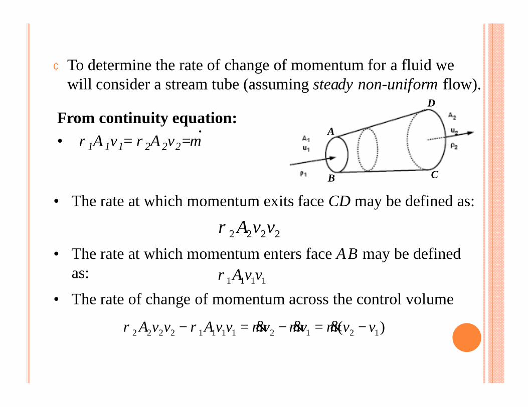
¢ To determine the rate of change of momentum for a fluid we will consider a stream tube (assuming steady non-uniform flow).
2222 vvAρ• The rate at which momentum exits face CD may be defined as:
B
A
D
C
From continuity equation:• ρ1A1v1= ρ2A2v2=m
.
• The rate at which momentum enters face AB may be defined as: 1111 vvAρ
• The rate of change of momentum across the control volume
)( 121211112222 vvmvmvmvvAvvA −=−=− &&&ρρ
٥
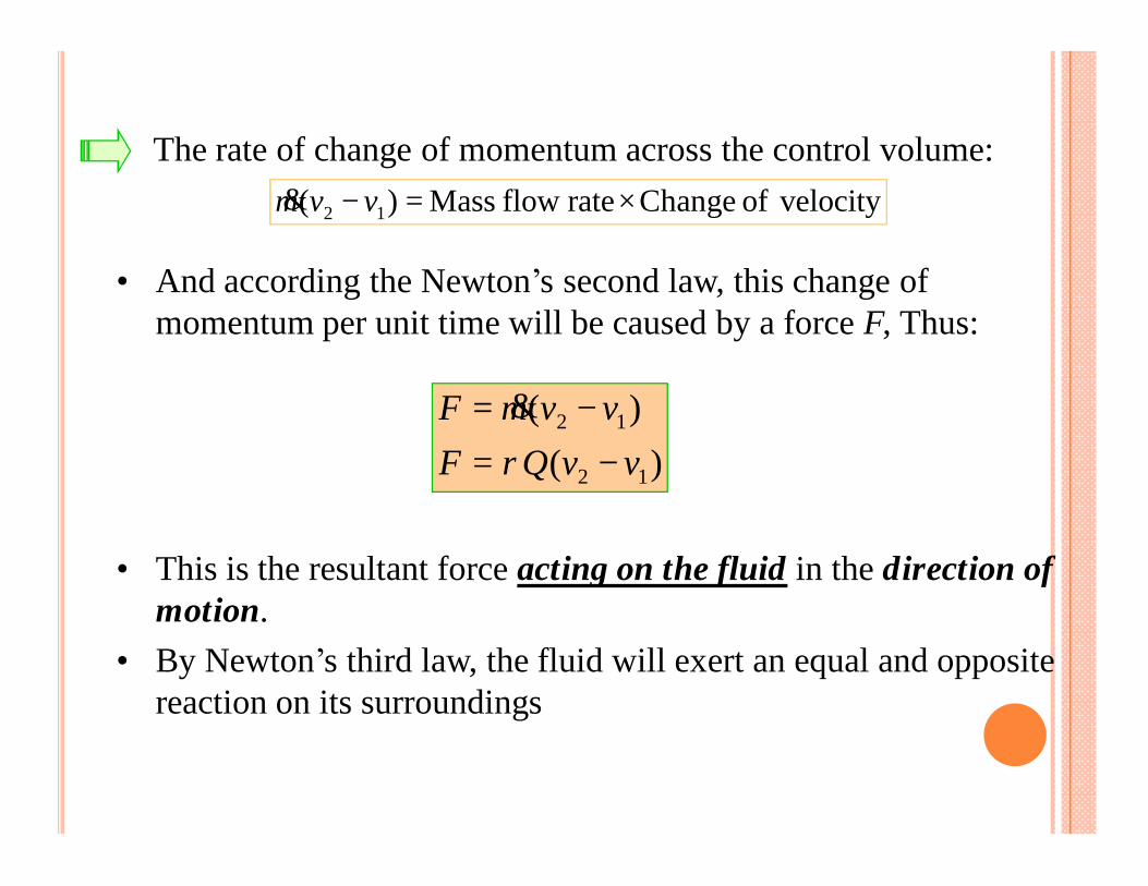
velocityof Changerate flow Mass )( 12 ×=− vvm&
• And according the Newton’s second law, this change of momentum per unit time will be caused by a force F, Thus:
The rate of change of momentum across the control volume:
)()(
12
12
vvQFvvmF−=
−=ρ
&
• This is the resultant force acting on the fluid in the direction of motion.
• By Newton’s third law, the fluid will exert an equal and opposite reaction on its surroundings
٦

v1
v2
υ
φ
5.2 MOMENTUM EQUATION FOR TWO AND THREEDIMENSIONAL FLOW ALONG A STREAMLINE
¢ Consider the two dimensional system shown:
¢ Since both momentum and force are vector quantities, they can be resolving into components in the x and y directions
)()sinsin(direction in velocity of Change rate flow Mass
direction in momentum of change of Rate
1212 yy
y
vvmvvmy
yF
−=−=×=
=
&& θφ
• Similarly)()coscos(
direction in velocity of Change rate flow Mass direction in momentum of change of Rate
1212 xx
x
vvmvvmx
xF
−=−=×=
=
&& θφ
٧

¢ These components can be combined to give the resultant force:
)( 12 xxx vvmF −= &
)( 12 yyy vvmF −= &
22yx FFF +=
• And the angle of this force:
= −
x
y
FF1tanα α
• For a three-dimensional (x, y, z) system we then have an extra force to calculate and resolve in the z direction.
• This is considered in exactly the same way.٨
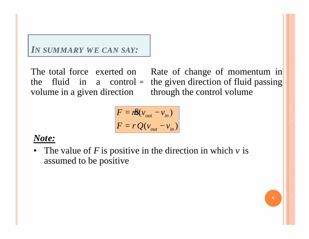
IN SUMMARY WE CAN SAY:
)()(
inout
inout
vvQFvvmF−=
−=ρ
&
The total force exerted onthe fluid in a controlvolume in a given direction
Rate of change of momentum inthe given direction of fluid passingthrough the control volume
=
Note:• The value of F is positive in the direction in which v is
assumed to be positive
٩

This force is made up of three components:¢ F1 =FR = Force exerted in the given direction on the fluid by
any solid body touching the control volume¢ F2 =FB = Force exerted in the given direction on the fluid by
body force (e.g. gravity)¢ F3 =FP = Force exerted in the given direction on the fluid by
fluid pressure outside the control volumeSo we say that the total force, FT, is given by the sum of these forces:
)( inoutPBRT vvmFFFF −=++= &
• The force exerted by the fluid on the solid body touching the control volume is equal and opposite to FR . So the reaction force, R, is given by:
RFR −=١٠

APPLICATION OF THE MOMENTUM EQUATION
We will consider the following examples:¢ Impact of a jet on a plane surface ¢Force due to flow round a curved vane ¢Force due to the flow of fluid round a pipe bend.¢Reaction of a jet.
١١
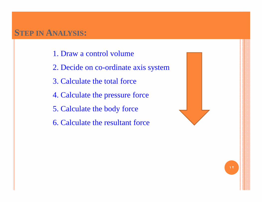
STEP IN ANALYSIS:
1. Draw a control volume
2. Decide on co-ordinate axis system
3. Calculate the total force
4. Calculate the pressure force
5. Calculate the body force
6. Calculate the resultant force
١٢

5.5 FORCE EXERTED BY A JET STRIKING A FLATPLATE
¢ Consider a jet striking a flat plate that may be perpendicularor inclined to the direction of the jet.
¢ This plate may be moving in the initial direction of the jet.
vv
Plate, normal to jet
υ 90o-υ
Plate, inclined to jet, angle (90o-υ )
• It is helpful to consider components of the velocity and force vectors perpendicular and parallel to the surface of the plate.
١٣

¢ The general term of the jet velocity component normal to the plate can be written as:
θcos)( uvvnormal −= v υ
• The mass flow entering the control volume)( uvAm −= ρ&
Avm ρ=&
• If the plate is stationary:
• Thus the rate of change of momentum normal to the plate:θρ cos))((momentum of change of Rate uvuvA −−=
θρ cos2Av=2Avρ=
if the plate is stationary and inclined
if the plate is both stationary and perpendicular
u
١٤

v υ• Force exerted normal to the plate = The rate of change of momentum normal to the plate:
θρ cos))(( plate the tonormal exerted Force uvuvA −−=
• There will be an equal and opposite reaction force exerted on the jet by the plate.
• In the direction parallel to the plate, the force exerted will depend upon the shear stress between the fluid and the surface of the plate.
• For ideal fluid there would be no shear stress and hence no force parallel to the plate
u
١٥

EXAMPLE 1A flat plate is struck normally by a jet of water 50 mm in diameter with a velocity of 18 m/s. calculate:
1. The force on the plate when it is stationary.2. The force on the plate when it moves in the same direction as
the jet with a velocity of 6m/s
x
yv u
١٦

EXAMPLE 2¢ A jet of water from a fixed nozzle has a diameter d of 25mm
and strikes a flat plate at angle υ of 30o to the normal to the plate. The velocity of the jet v is 5m/s, and the surface of the plate can be assumed to be frictionless.
¢ Calculate the force exerted normal to the plate (a) if the plate is stationary, (b) if the plate is moving with velocity u of 2m/s in the same direction as the jet
v 30o u
x
y
١٧
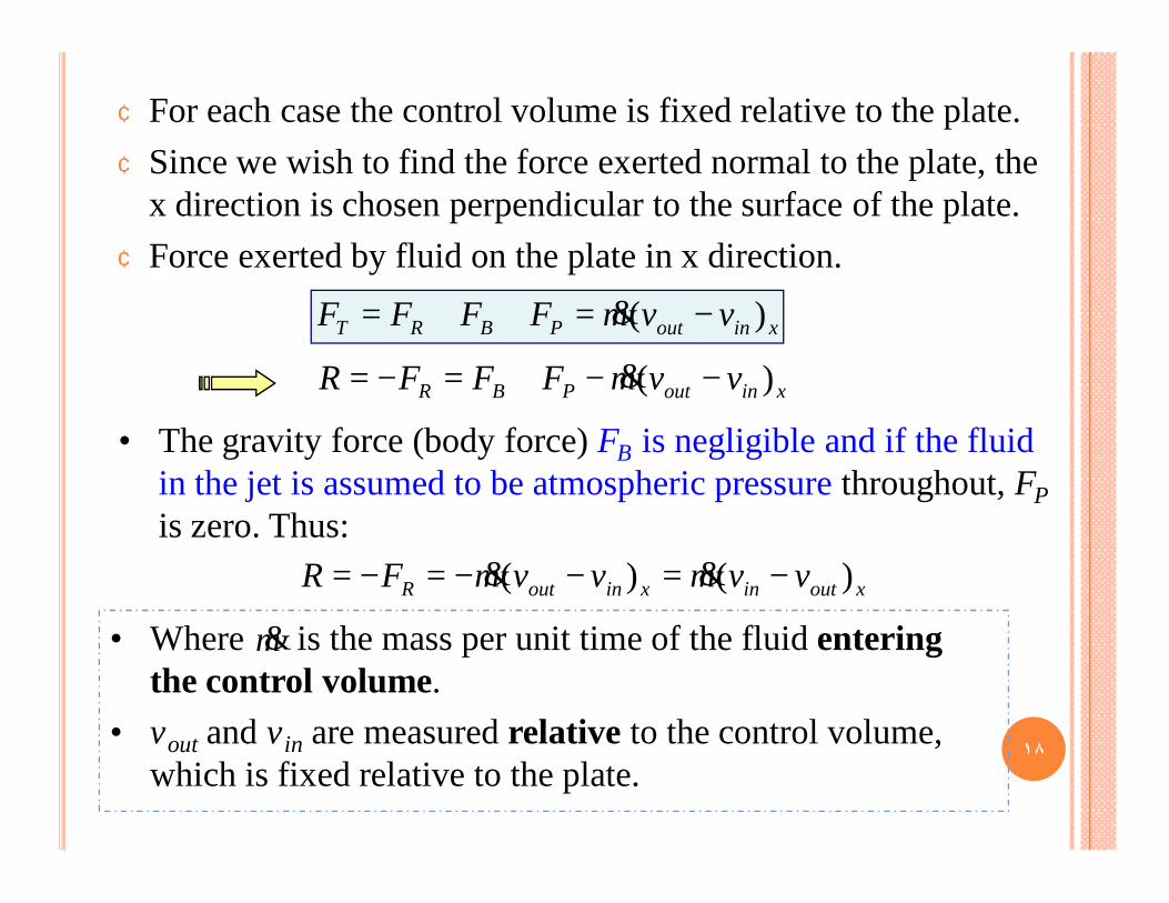
¢ For each case the control volume is fixed relative to the plate.¢ Since we wish to find the force exerted normal to the plate, the
x direction is chosen perpendicular to the surface of the plate.¢ Force exerted by fluid on the plate in x direction.
xinoutPBR vvmFFFR )( −−+=−= &
xinoutPBRT vvmFFFF )( −=++= &
• The gravity force (body force) FB is negligible and if the fluid in the jet is assumed to be atmospheric pressure throughout, FPis zero. Thus:
xoutinxinoutR vvmvvmFR )()( −=−−=−= &&
• Where is the mass per unit time of the fluid entering the control volume.
• vout and vin are measured relative to the control volume, which is fixed relative to the plate.
m&
١٨
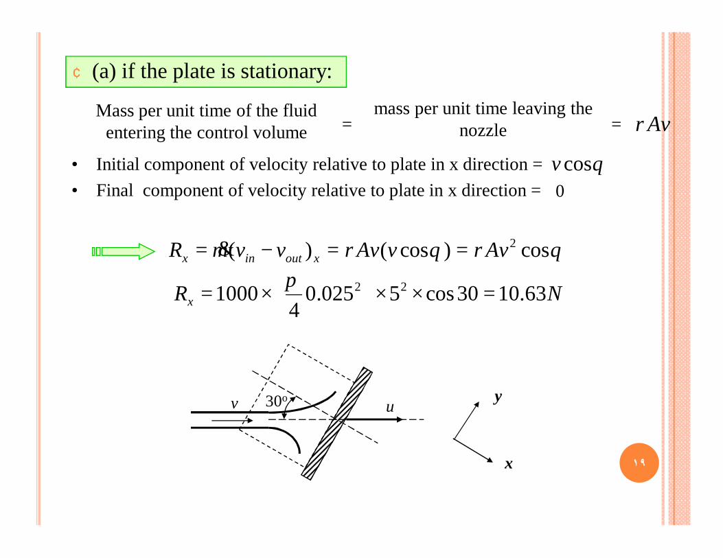
¢ (a) if the plate is stationary:
θρθρ cos)cos()( 2AvvAvvvmR xoutinx ==−= &
mass per unit time leaving the nozzle
Mass per unit time of the fluid entering the control volume = = Avρ
• Initial component of velocity relative to plate in x direction = • Final component of velocity relative to plate in x direction =
θcosv0
NRx 63.1030cos5025.04
1000 22 =××
×=
π
v 30o u
x
y
١٩

¢ (b) if the plate move:
θρθρ cos)(cos))(()( 2uvAuvuvAvvmR xoutinx −=−−=−= &
mass per unit time leaving the nozzle
Mass per unit time of the fluid entering the control volume = =
)( uvAAuAv −=−= ρρρ
• Initial component of velocity relative to plate in x direction = • Final component of velocity relative to plate in x direction =
θcos)( uv −0
NRx 83.330cos)25(025.04
1000 22 =×−×
×=
π
v 30o u
x
y
-mass per unit time
required to extent jet
٢٠

HW: EXAMPLE 5.2 PAGE 121
See other examples (in the class)
٢١

5.6 FORCE DUE TO DEFLECTION OF A JET BY ACURVED VANE
¢ Both velocity and momentum are vector quantities
¢ Even if the magnitude of the velocity remains unchanged, a changed in direction of a stream of fluid will give rise to a change of momentum.
• If the stream is deflected by a curved vane (entering and leaving tangentially without impact). A force will be exerted between the fluid and the surface of the vane to cause this change in momentum. ٢٢

¢ It is usually convenient to calculate the components of this force parallel and perpendicular to the direction of the incoming stream
¢ The resultant can be combined to give the magnitude of the resultant force which the vane exerts on the fluid, and equal and opposite reaction of the fluid on the vane.
Note:• the pressure force is zero as the pressure at
both the inlet and the outlets are atmospheric.
• No body forces in the x-direction
• In the y-direction the body force acting is the weight of the fluid.
• (This is often small is the jet volume is small and sometimes ignored in analysis.)
٢٣
EXAMPLE 5.3 PAGE 123
٢٤
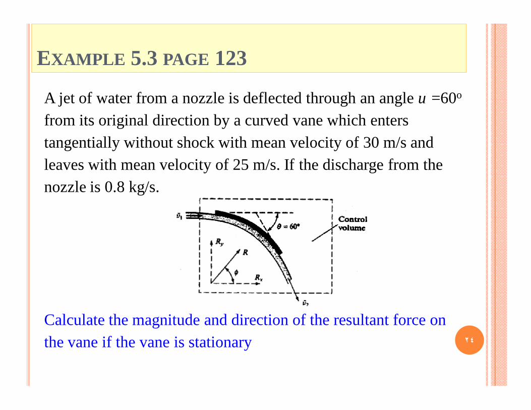
A jet of water from a nozzle is deflected through an angle υ =60o
from its original direction by a curved vane which enters tangentially without shock with mean velocity of 30 m/s and leaves with mean velocity of 25 m/s. If the discharge from the nozzle is 0.8 kg/s.
Calculate the magnitude and direction of the resultant force on the vane if the vane is stationary

5.8 FORCE EXERTED ON A PIPE BENDS AND CLOSEDCONDUITS
A force will act on the bend due to:¢ The fluid changes its direction¢ If the pipe tapers, there is a change in velocity magnitude.¢ Do not forget pressure forces.
• This force can be very large in the case of water supply pipes.
• If the bend is not fixed it will move and eventually break at the joints.
• We need to know how much force a support (thrust block) must withstand.
Why do we want to know the forces here?
٢٥
EXAMPLE 5.5 PAGE 1271
2
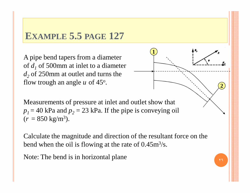
A pipe bend tapers from a diameter of d1 of 500mm at inlet to a diameter d2 of 250mm at outlet and turns the flow trough an angle υ of 45o.
Calculate the magnitude and direction of the resultant force on the bend when the oil is flowing at the rate of 0.45m3/s.
Note: The bend is in horizontal plane
Measurements of pressure at inlet and outlet show that p1 = 40 kPa and p2 = 23 kPa. If the pipe is conveying oil (ρ = 850 kg/m3).
٢٦

5.9 REACTION OF A JET
¢ Whenever the momentum of a stream of fluid increased in a given direction in passing from one section to another, there must be a net force acting on the fluid in that direction.
¢ By Newton’s third law, there will be an equal and opposite force exerted by the fluid on the system.
Typical example:¢ Force on the nozzle at the outlet of a pipe. Anything holding
the nozzle (e.g. a fireman) must be strong enough to withstand these forces.
¢ The reactive force exerted when the fluid is discharge in the form of high-velocity jet. (aircraft, rocket motors…)
٢٧

EXAMPLE 5.6 PAGE 129A jet of water of diameter d = 50 mm issues with velocity of 4.9 m/s from a hole in the vertical side of an open tank which kept filled with water to a height of 1.5 m above the center of the hole. Calculate the reaction of the jet on the tank and its contents when:
1. It is stationary.
2. Its moving with a velocity u = 1.2m/s in the opposite direction to the jet while the velocity of the jet relative to the tank remains unchanged.
3. In the latter case, what would be the work done per second.
٢٨

5.12 EULER’S EQUATION OF MOTION ALONG ASTREAMLINE
It is an equation shows the relationship between velocity, pressure, elevation and density along a streamline
Mass per unit time flowing = ρAv
Rate of increase of momentum from AB to CD (in direction of motion) = ρAv [(v+δv) - v]= ρAvδv ٢٩

The force acting to produce this increase of momentum in the direction of motion are:
• Force due to p in direction of motion = pA• Force due to p+δp opposing motion = (p+δp)(A+δA)• Force due to pside producing a component in the direction of motion =
pside δA• Force due to mg producing a component opposing motion = mg cosυ
Resultant force in the direction of motion =pA- (p+δp)(A+δA)+ pside δA - mg cosυ
pside=p+kδp where k is a fraction
mg = ρg (Volume)= ρg (A+0.5δA) δs
cosυ = δz / δs
٣٠

ρAvδv = - Aδp -ρgAδz
• Neglecting the product of small quantities:Resultant force in the direction of motion = - Aδp - ρgAδz
• Dividing by : ρAδs
• Applying Newton’s second law:
01=++
szg
svv
sp
δδ
δδ
δδ
ρ
• Or, in the limit as δs è 0
01=++
dsdzg
dsdvv
dsdp
ρ
Giving, in differential form, the relationship between velocity v, pressure p, elevation z and density ρ along a streamline for steady flow
This is known as Euler’s Euler’s equationequation
٣١
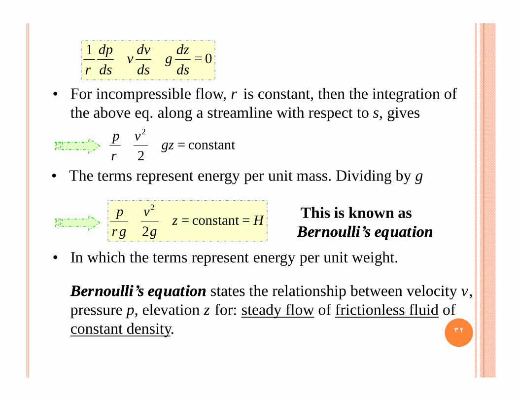
• For incompressible flow, ρ is constant, then the integration of the above eq. along a streamline with respect to s, gives
• The terms represent energy per unit mass. Dividing by g
01=++
dsdzg
dsdvv
dsdp
ρ
constant2
2
=++ gzvpρ
Hzg
vgp
==++ constant2
2
ρ
• In which the terms represent energy per unit weight.
This is known as Bernoulli’s equationBernoulli’s equation
Bernoulli’s equationBernoulli’s equation states the relationship between velocity v, pressure p, elevation z for: steady flow of frictionless fluid of constant density. ٣٢
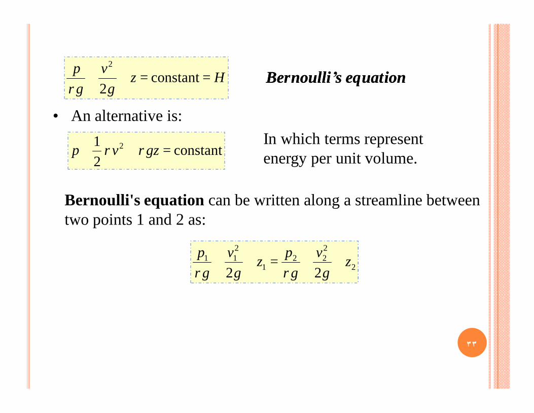
• An alternative is:
Bernoulli's equation can be written along a streamline between two points 1 and 2 as:
Hzg
vgp
==++ constant2
2
ρBernoulli’s equationBernoulli’s equation
In which terms represent energy per unit volume. constant
21 2 =++ gzvp ρρ
2
222
1
211
22z
gv
gpz
gv
gp
++=++ρρ
٣٣