
Chapter 5 internal_combustion_engine
53
INTERNAL COMBUSTION ENGINE
-
Upload
hashem-almahdi -
Category
Engineering
-
view
65 -
download
1
Transcript of Chapter 5 internal_combustion_engine
INTERNAL COMBUSTION
ENGINE
INTRODUCTION What is IC Engine? An internal combustion engine is a thermal system (power plant)
that converts heat obtained from chemical energy sources (gasoline, natural gas) into mechanical work.
Where are IC Engines Used?
IC engines are used as the propulsion systems for land transport vehicles such as automobiles (cars, etc.), marine vehicles (boats, etc.) and small airplanes.
IC engines are also used in portable electrical generators and as prime mover in grass cutting machine, etc.
2
3
INTRODUCTION
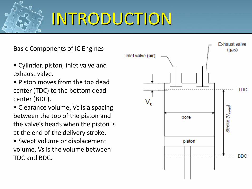
Basic Components of IC Engines • Cylinder, piston, inlet valve and exhaust valve. • Piston moves from the top dead center (TDC) to the bottom dead center (BDC). • Clearance volume, Vc is a spacing between the top of the piston and the valve’s heads when the piston is at the end of the delivery stroke. • Swept volume or displacement volume, Vs is the volume between TDC and BDC.
ENGINE CLASSIFICATION
4
Reciprocating internal combustion (IC) engines are classified into two general categories, depending on how the combustion process in the cylinder is initiated, i.e.: a) Spark-ignition (SI) engines; b) Compression-ignition (CI) engines. Description of SI Engines • Run on liquid fuel such as gasoline or petrol, which is mixed with
air. • The air-fuel mixture enters the cylinder and is compressed to a
highest pressure and temperature.
ENGINE CLASSIFICATION
5
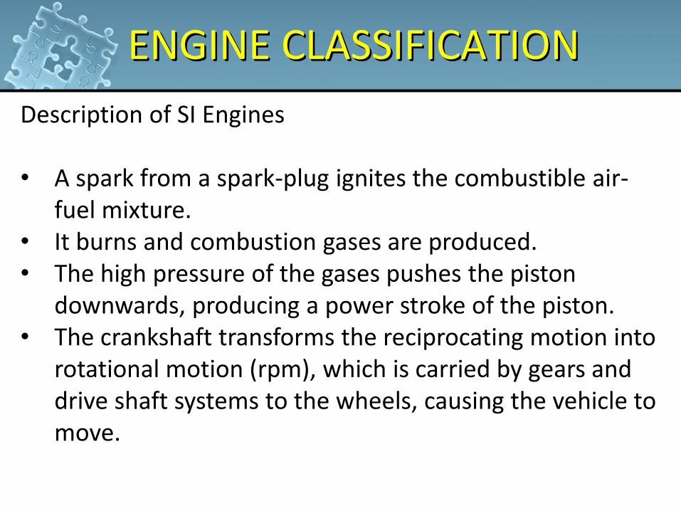
Description of SI Engines • A spark from a spark-plug ignites the combustible air-
fuel mixture. • It burns and combustion gases are produced. • The high pressure of the gases pushes the piston
downwards, producing a power stroke of the piston. • The crankshaft transforms the reciprocating motion into
rotational motion (rpm), which is carried by gears and drive shaft systems to the wheels, causing the vehicle to move.

ENGINE CLASSIFICATION
6
Description of CI Engines Run on diesel liquid fuel. • The fresh atmospheric air enters the cylinder in which it is
compressed to about 1/22 of its original volume, causing its temperature to raise to about 540 oC or higher.
• Diesel fuel is then injected into the compressed air. • The heat of compression of the air causes the diesel to
burn.
ENGINE CLASSIFICATION
7
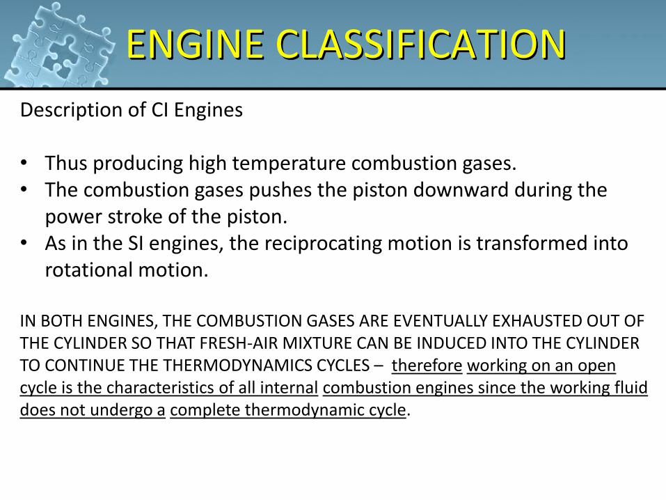
Description of CI Engines • Thus producing high temperature combustion gases. • The combustion gases pushes the piston downward during the
power stroke of the piston. • As in the SI engines, the reciprocating motion is transformed into
rotational motion. IN BOTH ENGINES, THE COMBUSTION GASES ARE EVENTUALLY EXHAUSTED OUT OF THE CYLINDER SO THAT FRESH-AIR MIXTURE CAN BE INDUCED INTO THE CYLINDER TO CONTINUE THE THERMODYNAMICS CYCLES – therefore working on an open cycle is the characteristics of all internal combustion engines since the working fluid does not undergo a complete thermodynamic cycle.
PERFORMANCE CRITERIA
8
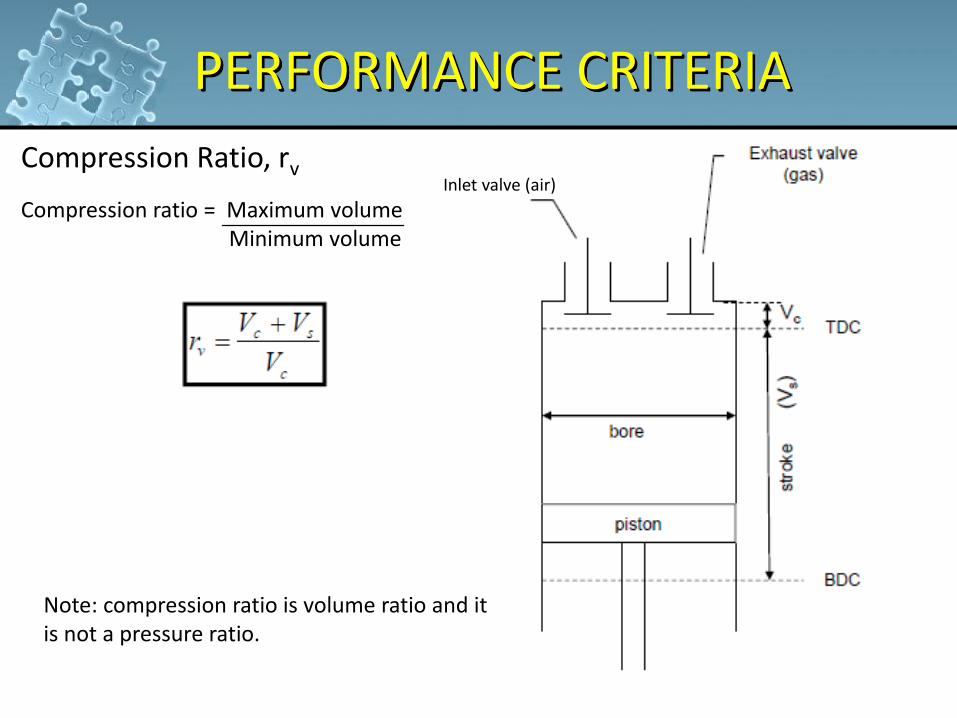
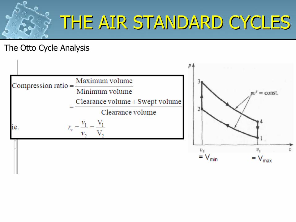
Compression Ratio, rv
Compression ratio = Maximum volume Minimum volume
Note: compression ratio is volume ratio and it is not a pressure ratio.
Inlet valve (air)
PERFORMANCE CRITERIA
9
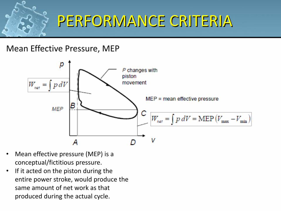
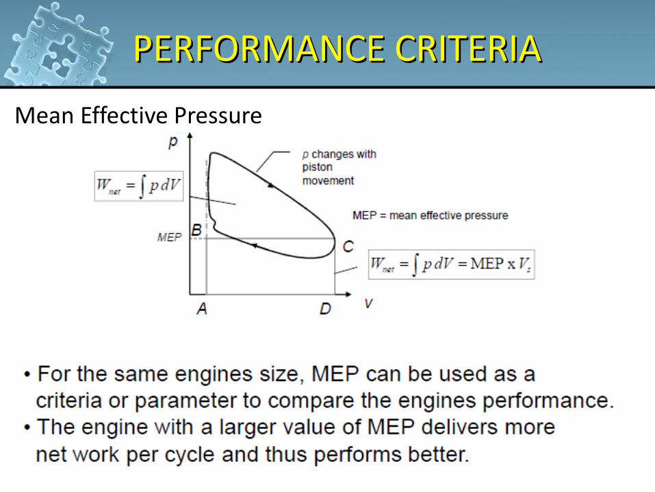
Mean Effective Pressure, MEP • Mean effective pressure (MEP) is a
conceptual/fictitious pressure. • If it acted on the piston during the
entire power stroke, would produce the same amount of net work as that produced during the actual cycle.
PERFORMANCE CRITERIA
10
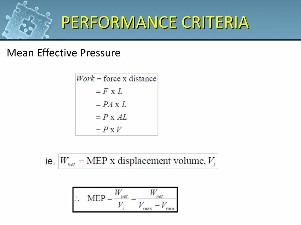
Mean Effective Pressure
PERFORMANCE CRITERIA
11
Mean Effective Pressure
CLASSIFICATION BY CYCLES
12
Reciprocating internal combustion engines operate either on two-stroke or four-stroke cycle. Four-stroke Cycle • Most automotive engines operate on a 4-stroke cycle. • Every fourth piston stroke is the power stroke. • The crankshaft makes two revolutions to complete the cycle.
CLASSIFICATION BY CYCLES
13
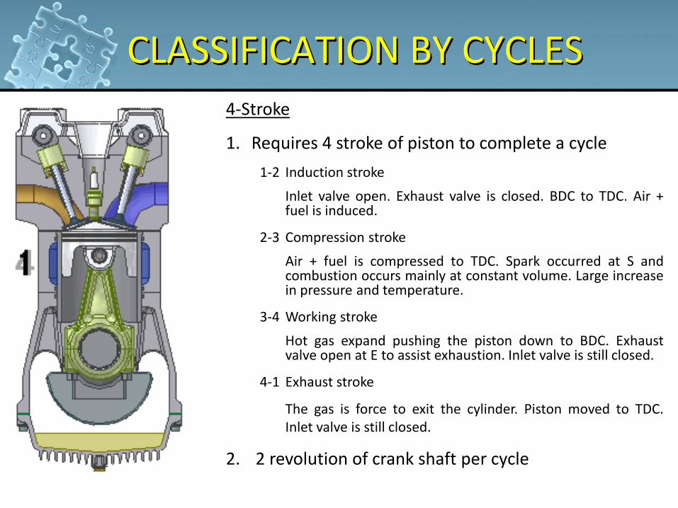
4-Stroke
1. Requires 4 stroke of piston to complete a cycle
1-2 Induction stroke
Inlet valve open. Exhaust valve is closed. BDC to TDC. Air + fuel is induced.
2-3 Compression stroke
Air + fuel is compressed to TDC. Spark occurred at S and combustion occurs mainly at constant volume. Large increase in pressure and temperature.
3-4 Working stroke
Hot gas expand pushing the piston down to BDC. Exhaust valve open at E to assist exhaustion. Inlet valve is still closed.
4-1 Exhaust stroke
The gas is force to exit the cylinder. Piston moved to TDC. Inlet valve is still closed.
2. 2 revolution of crank shaft per cycle
CLASSIFICATION BY CYCLES
14
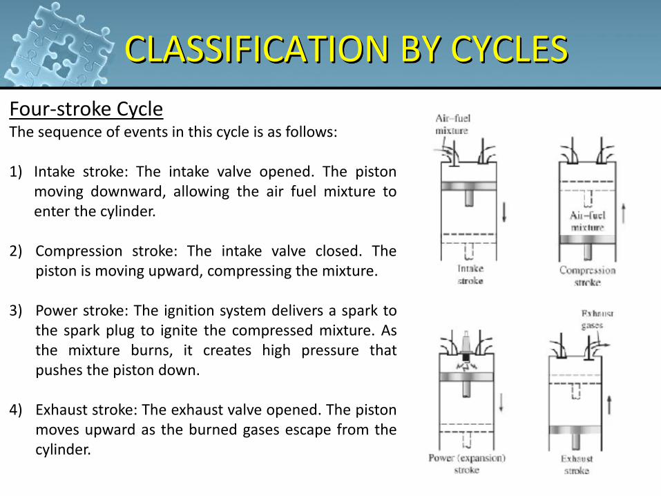
Four-stroke Cycle The sequence of events in this cycle is as follows: 1) Intake stroke: The intake valve opened. The piston
moving downward, allowing the air fuel mixture to enter the cylinder.
2) Compression stroke: The intake valve closed. The piston is moving upward, compressing the mixture. 3) Power stroke: The ignition system delivers a spark to the spark plug to ignite the compressed mixture. As the mixture burns, it creates high pressure that pushes the piston down. 4) Exhaust stroke: The exhaust valve opened. The piston moves upward as the burned gases escape from the cylinder.
CLASSIFICATION BY CYCLES
15
CLASSIFICATION BY CYCLES
16
THE AIR STANDARD CYCLES
17
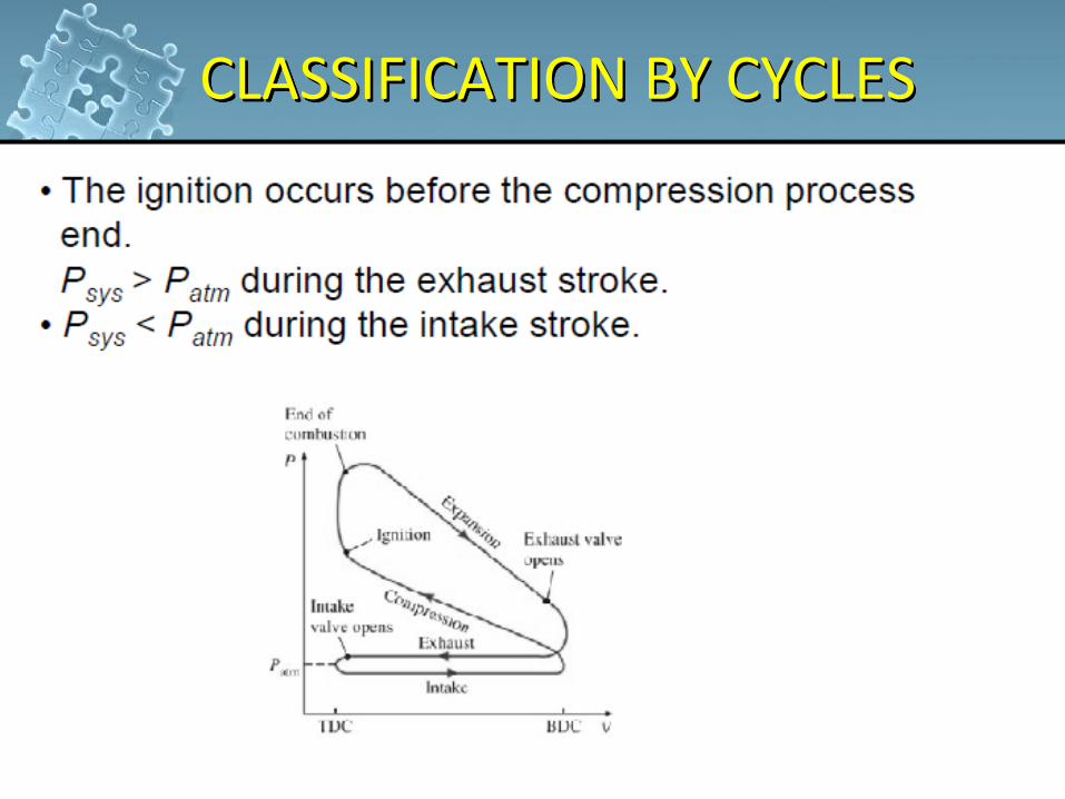
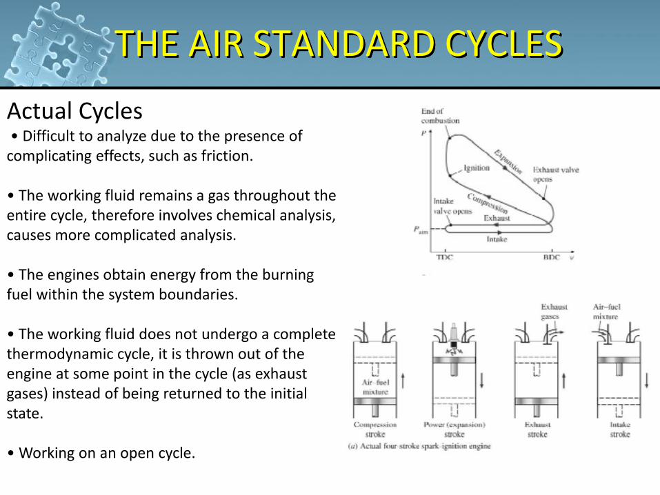
Actual Cycles • Difficult to analyze due to the presence of complicating effects, such as friction. • The working fluid remains a gas throughout the entire cycle, therefore involves chemical analysis, causes more complicated analysis. • The engines obtain energy from the burning fuel within the system boundaries. • The working fluid does not undergo a complete thermodynamic cycle, it is thrown out of the engine at some point in the cycle (as exhaust gases) instead of being returned to the initial state. • Working on an open cycle.
18
THE AIR STANDARD CYCLES Ideal Cycle
• To make an analytical study of a cycle practicable, the complexities are kept at a manageable level and utilize some idealizations. • Models developed from these idealizations are simple and able to study the effects of major parameters towards actual engines performance, since they still retain the general characteristics of the actual engines they represent. • Such a cycle is called an ideal cycle.
19
THE AIR STANDARD CYCLES
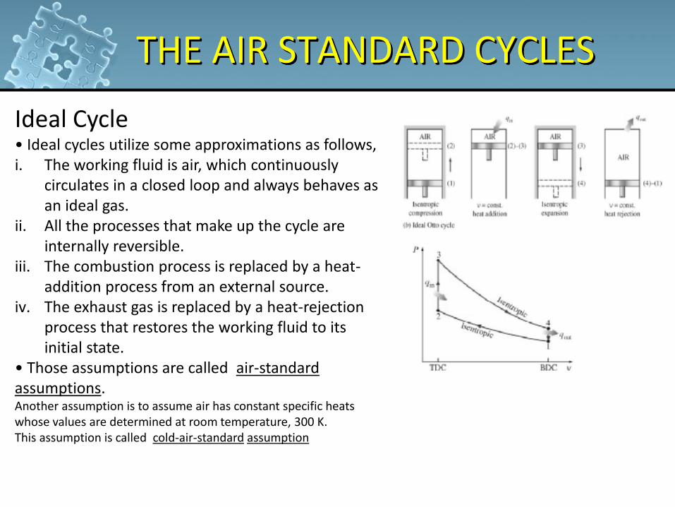
Ideal Cycle • Ideal cycles utilize some approximations as follows, i. The working fluid is air, which continuously
circulates in a closed loop and always behaves as an ideal gas.
ii. All the processes that make up the cycle are internally reversible.
iii. The combustion process is replaced by a heat-addition process from an external source.
iv. The exhaust gas is replaced by a heat-rejection process that restores the working fluid to its initial state.
• Those assumptions are called air-standard assumptions. Another assumption is to assume air has constant specific heats whose values are determined at room temperature, 300 K. This assumption is called cold-air-standard assumption
20
THE AIR STANDARD CYCLES Carnot Cycle
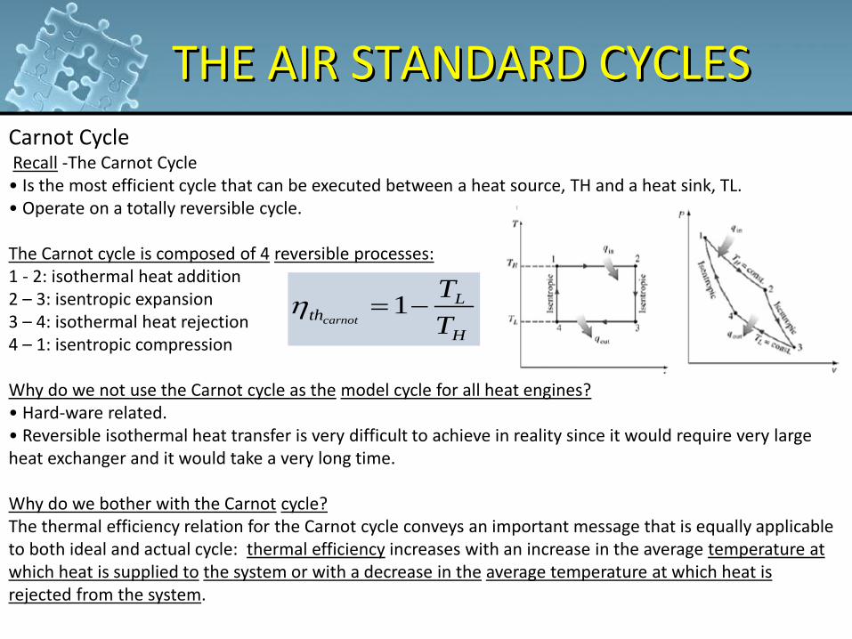
Recall -The Carnot Cycle • Is the most efficient cycle that can be executed between a heat source, TH and a heat sink, TL. • Operate on a totally reversible cycle. The Carnot cycle is composed of 4 reversible processes: 1 - 2: isothermal heat addition 2 – 3: isentropic expansion 3 – 4: isothermal heat rejection 4 – 1: isentropic compression Why do we not use the Carnot cycle as the model cycle for all heat engines? • Hard-ware related. • Reversible isothermal heat transfer is very difficult to achieve in reality since it would require very large heat exchanger and it would take a very long time. Why do we bother with the Carnot cycle? The thermal efficiency relation for the Carnot cycle conveys an important message that is equally applicable to both ideal and actual cycle: thermal efficiency increases with an increase in the average temperature at which heat is supplied to the system or with a decrease in the average temperature at which heat is rejected from the system.
H
Lth
T
Tcarnot
1
21
THE AIR STANDARD CYCLES
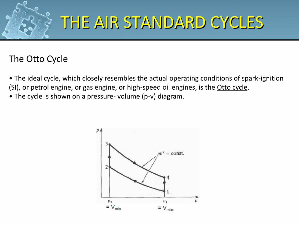
The Otto Cycle • The ideal cycle, which closely resembles the actual operating conditions of spark-ignition (SI), or petrol engine, or gas engine, or high-speed oil engines, is the Otto cycle. • The cycle is shown on a pressure- volume (p-v) diagram.
22
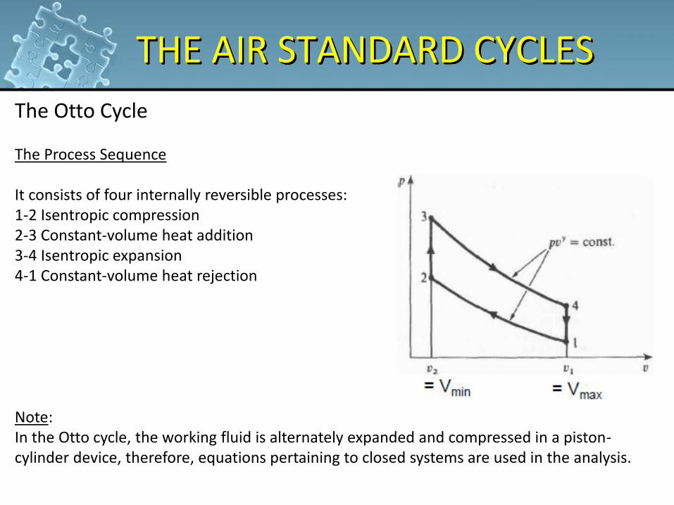
THE AIR STANDARD CYCLES The Otto Cycle
The Process Sequence It consists of four internally reversible processes: 1-2 Isentropic compression 2-3 Constant-volume heat addition 3-4 Isentropic expansion 4-1 Constant-volume heat rejection Note: In the Otto cycle, the working fluid is alternately expanded and compressed in a piston-cylinder device, therefore, equations pertaining to closed systems are used in the analysis.
23
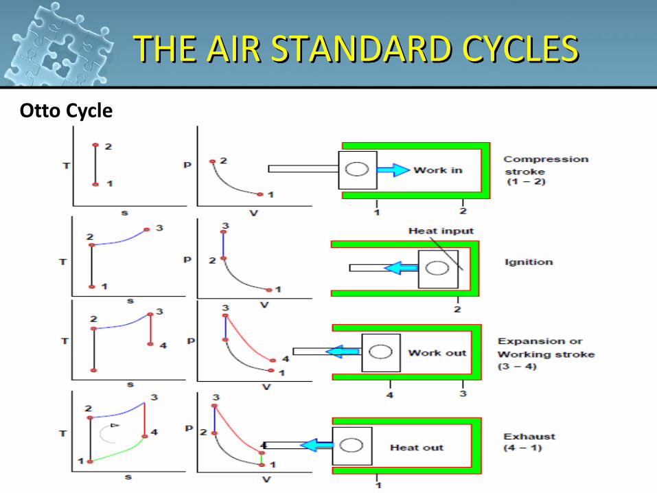
THE AIR STANDARD CYCLES Otto Cycle
24
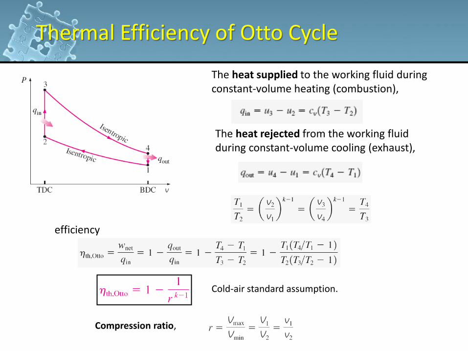
Thermal Efficiency of Otto Cycle
The heat supplied to the working fluid during constant-volume heating (combustion),
The heat rejected from the working fluid during constant-volume cooling (exhaust),
Thermal efficiency,
Temperature-volume relation,
Compression ratio,
Cold-air standard assumption.
25
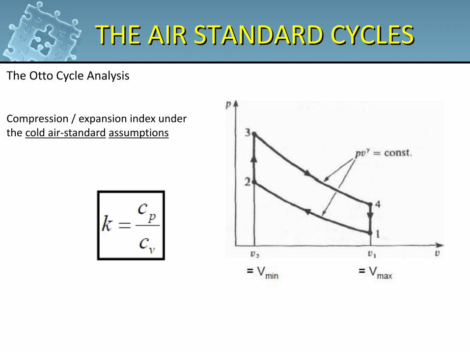
THE AIR STANDARD CYCLES The Otto Cycle Analysis
Compression / expansion index under the cold air-standard assumptions
26
THE AIR STANDARD CYCLES The Otto Cycle Analysis
27
THE AIR STANDARD CYCLES
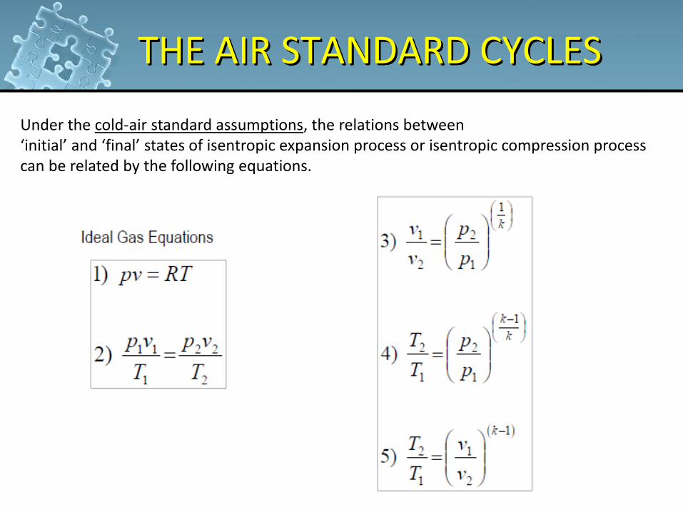
Under the cold-air standard assumptions, the relations between ‘initial’ and ‘final’ states of isentropic expansion process or isentropic compression process can be related by the following equations.
28
THE AIR STANDARD CYCLES
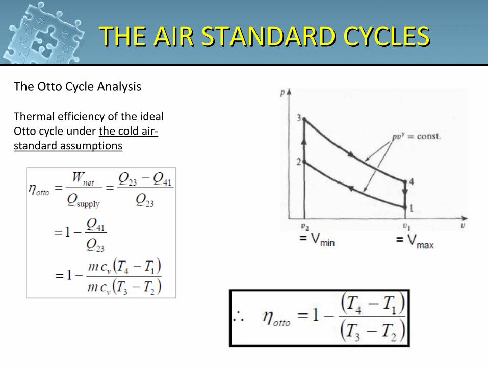
The Otto Cycle Analysis Thermal efficiency of the ideal Otto cycle under the cold air-standard assumptions
29
THE AIR STANDARD CYCLES
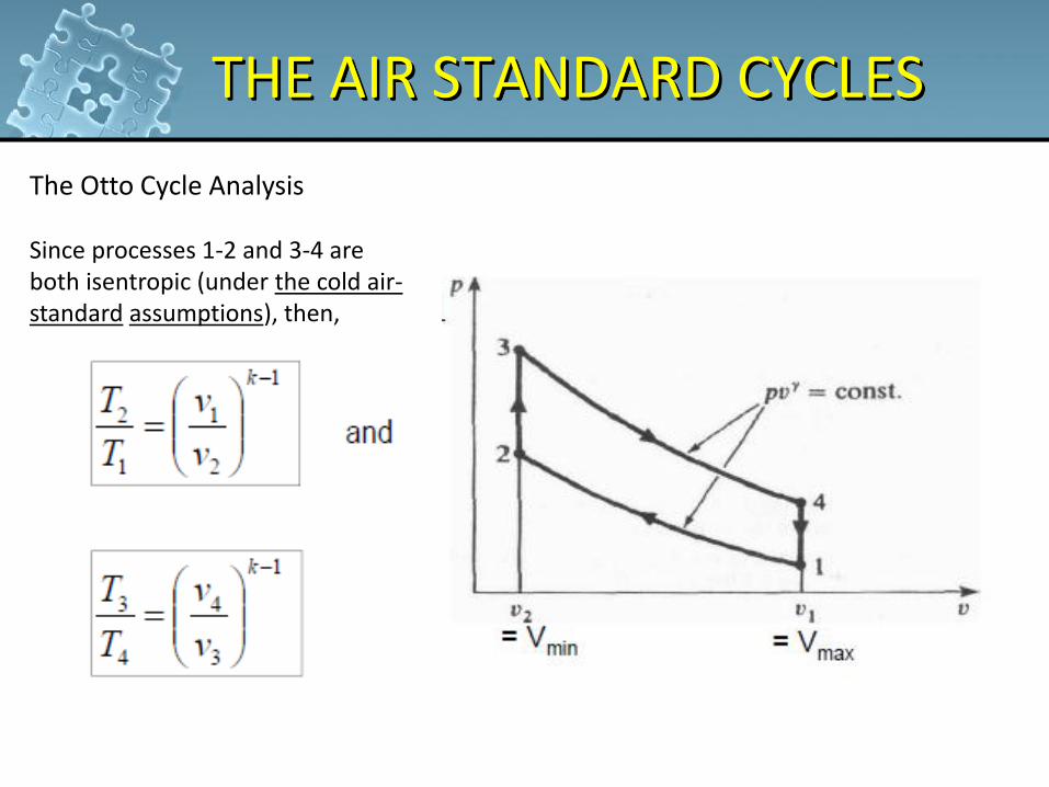
The Otto Cycle Analysis Since processes 1-2 and 3-4 are both isentropic (under the cold air-standard assumptions), then,
30
THE AIR STANDARD CYCLES
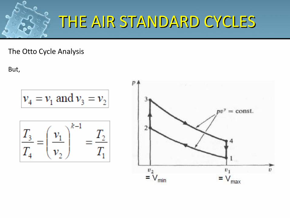
The Otto Cycle Analysis But,

31
THE AIR STANDARD CYCLES
The Otto Cycle Analysis Thermal efficiency of the ideal Otto cycle under the cold air-standard assumptions
32
THE AIR STANDARD CYCLES
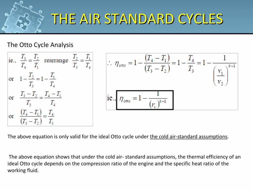
The Otto Cycle Analysis
The above equation is only valid for the ideal Otto cycle under the cold air-standard assumptions. The above equation shows that under the cold air- standard assumptions, the thermal efficiency of an ideal Otto cycle depends on the compression ratio of the engine and the specific heat ratio of the working fluid.
33
THE AIR STANDARD CYCLES
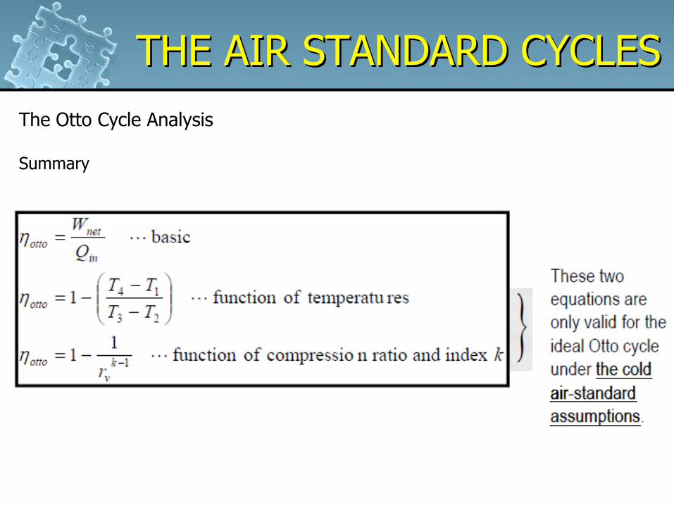
The Otto Cycle Analysis Summary
Example
34
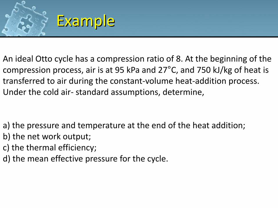
An ideal Otto cycle has a compression ratio of 8. At the beginning of the compression process, air is at 95 kPa and 27°C, and 750 kJ/kg of heat is transferred to air during the constant-volume heat-addition process. Under the cold air- standard assumptions, determine, a) the pressure and temperature at the end of the heat addition; b) the net work output; c) the thermal efficiency; d) the mean effective pressure for the cycle.
Example
35
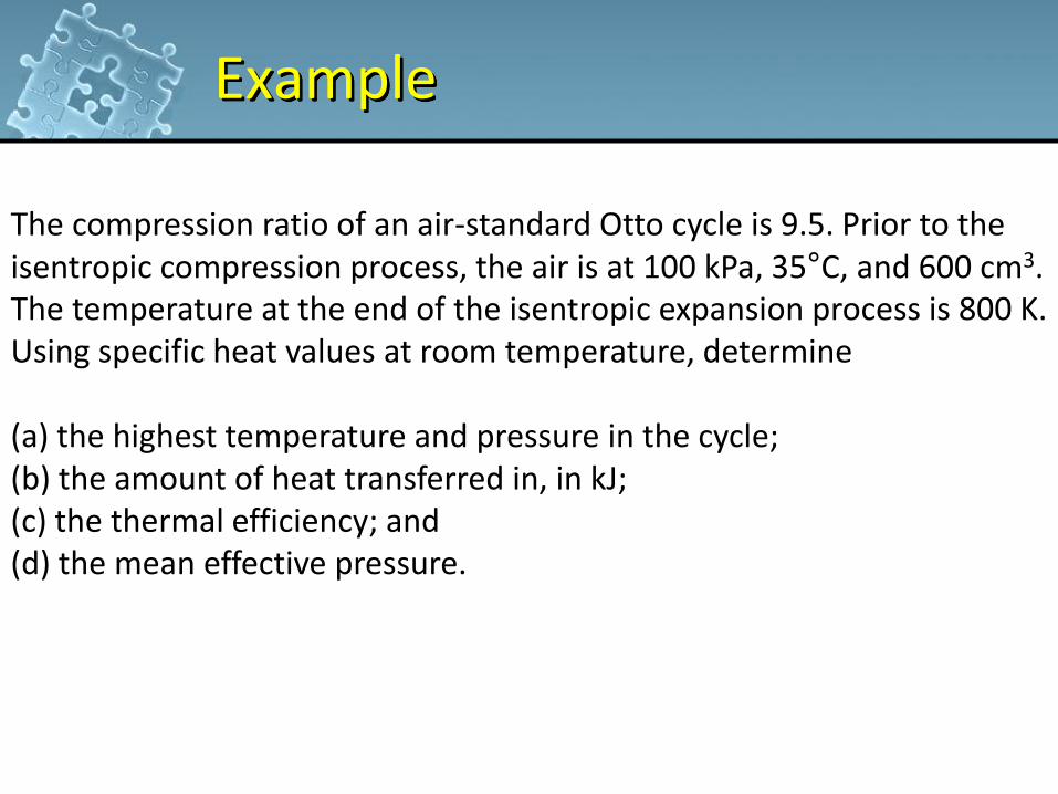
The compression ratio of an air-standard Otto cycle is 9.5. Prior to the isentropic compression process, the air is at 100 kPa, 35°C, and 600 cm3. The temperature at the end of the isentropic expansion process is 800 K. Using specific heat values at room temperature, determine (a) the highest temperature and pressure in the cycle; (b) the amount of heat transferred in, in kJ; (c) the thermal efficiency; and (d) the mean effective pressure.
Example
36
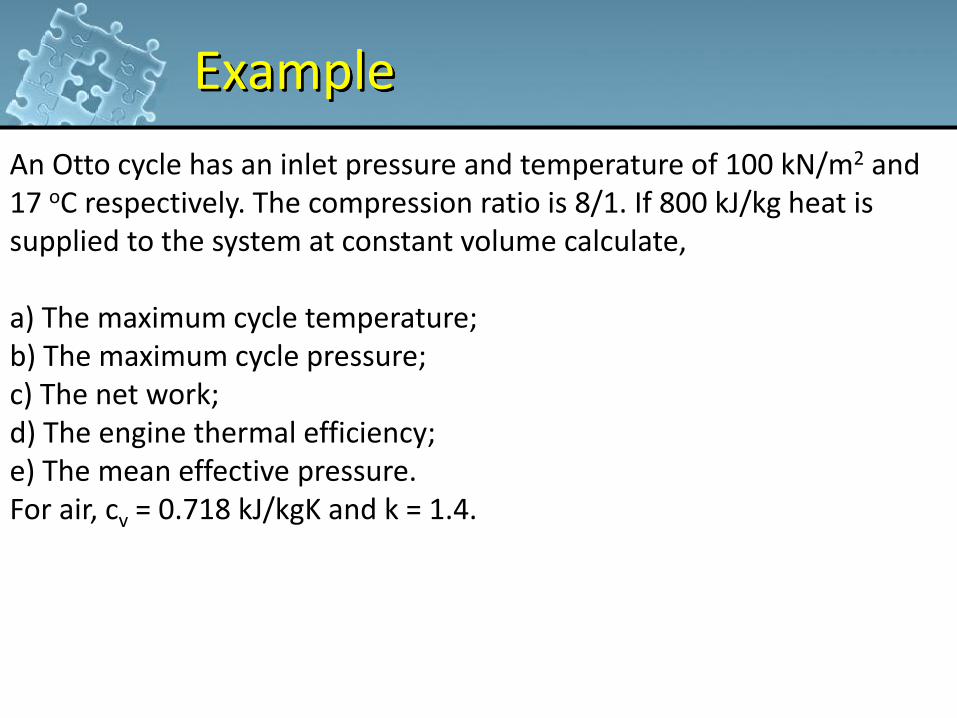
An Otto cycle has an inlet pressure and temperature of 100 kN/m2 and 17 oC respectively. The compression ratio is 8/1. If 800 kJ/kg heat is supplied to the system at constant volume calculate, a) The maximum cycle temperature; b) The maximum cycle pressure; c) The net work; d) The engine thermal efficiency; e) The mean effective pressure. For air, cv = 0.718 kJ/kgK and k = 1.4.
Example
37
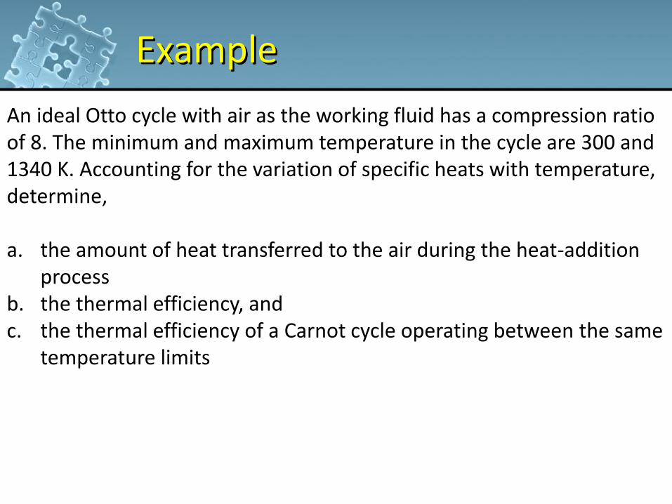
An ideal Otto cycle with air as the working fluid has a compression ratio of 8. The minimum and maximum temperature in the cycle are 300 and 1340 K. Accounting for the variation of specific heats with temperature, determine, a. the amount of heat transferred to the air during the heat-addition
process b. the thermal efficiency, and c. the thermal efficiency of a Carnot cycle operating between the same
temperature limits
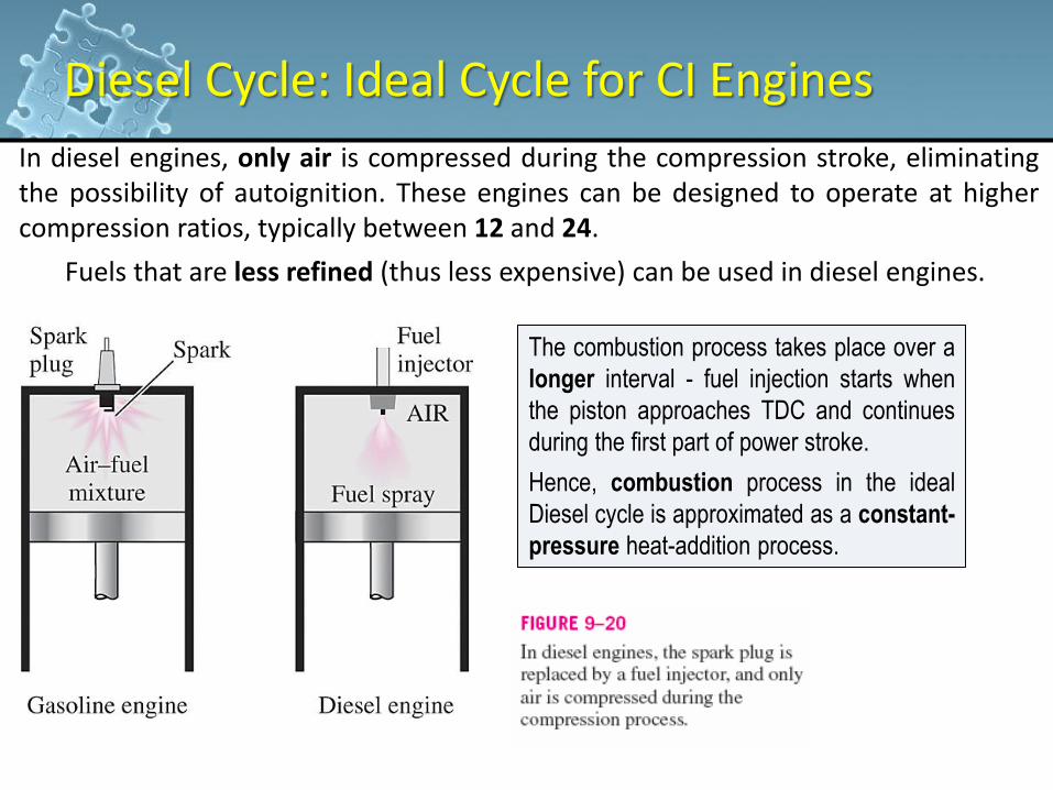
Diesel Cycle: Ideal Cycle for CI Engines
The combustion process takes place over a
longer interval - fuel injection starts when
the piston approaches TDC and continues
during the first part of power stroke.
Hence, combustion process in the ideal
Diesel cycle is approximated as a constant-
pressure heat-addition process.
In diesel engines, only air is compressed during the compression stroke, eliminating the possibility of autoignition. These engines can be designed to operate at higher compression ratios, typically between 12 and 24.
Fuels that are less refined (thus less expensive) can be used in diesel engines.
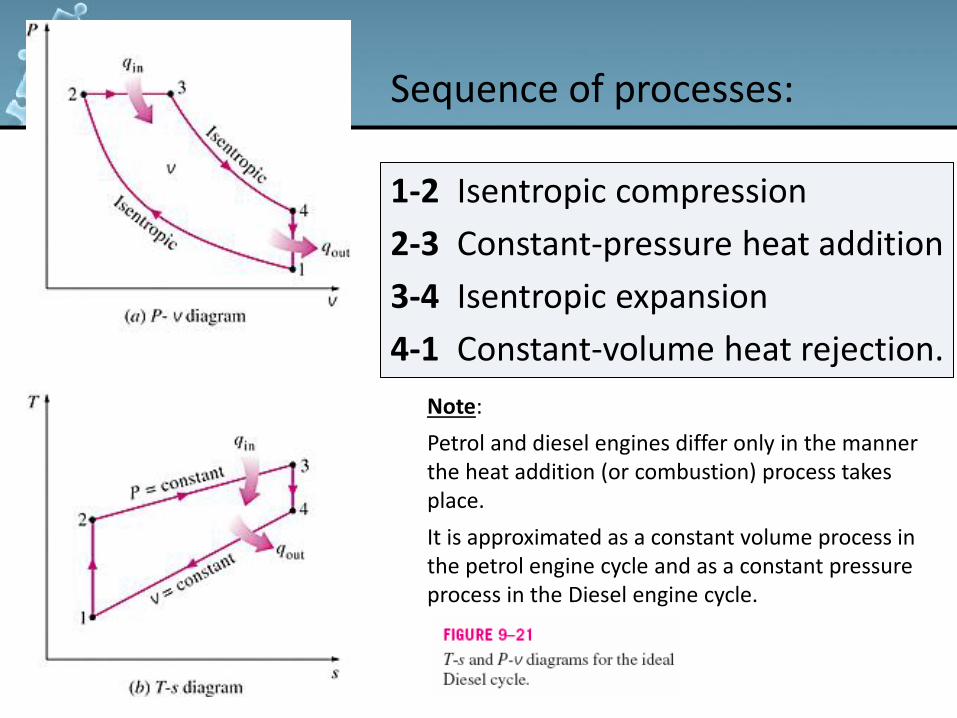
1-2 Isentropic compression
2-3 Constant-pressure heat addition
3-4 Isentropic expansion
4-1 Constant-volume heat rejection.
Sequence of processes:
Note:
Petrol and diesel engines differ only in the manner the heat addition (or combustion) process takes place.
It is approximated as a constant volume process in the petrol engine cycle and as a constant pressure process in the Diesel engine cycle.
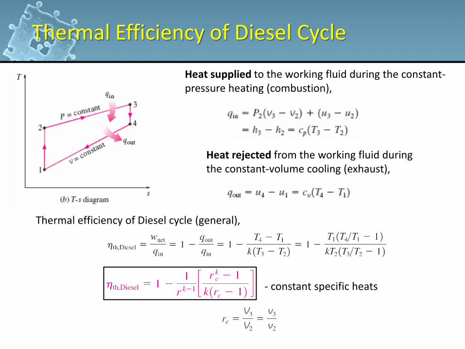
Cutoff ratio,
Thermal Efficiency of Diesel Cycle
Heat supplied to the working fluid during the constant-pressure heating (combustion),
Heat rejected from the working fluid during the constant-volume cooling (exhaust),
Thermal efficiency of Diesel cycle (general),
- constant specific heats
THE AIR STANDARD CYCLES
41
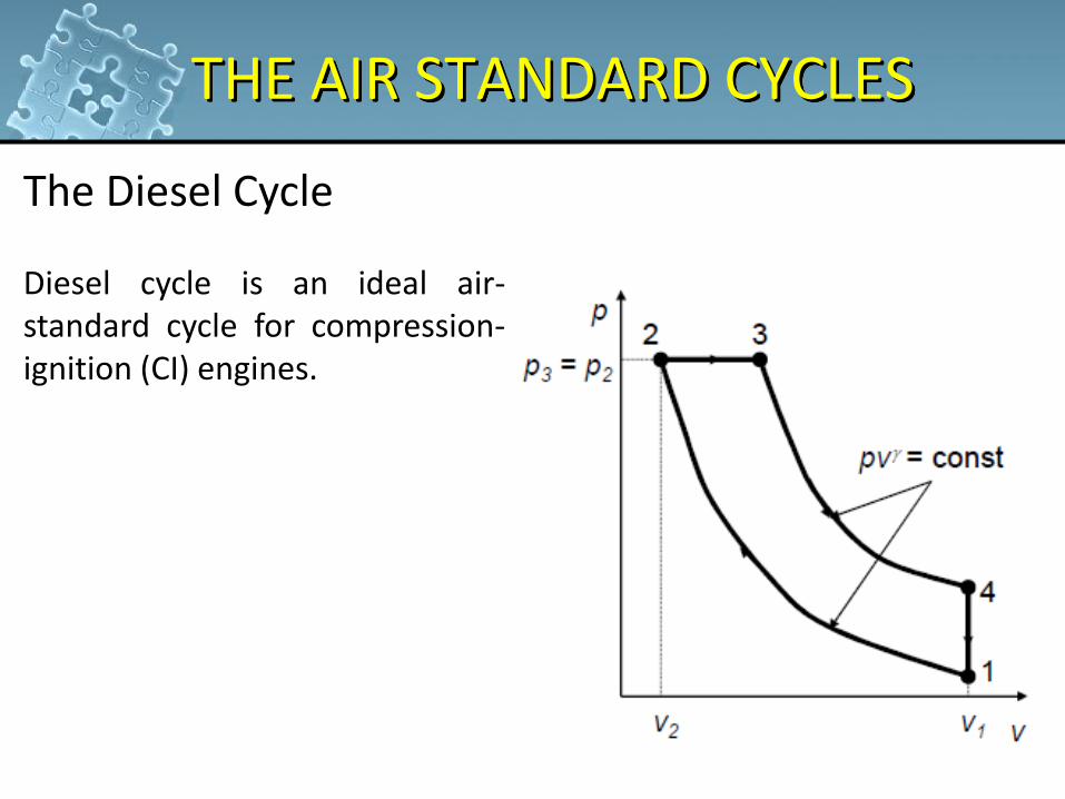
The Diesel Cycle Diesel cycle is an ideal air- standard cycle for compression- ignition (CI) engines.
THE AIR STANDARD CYCLES
42
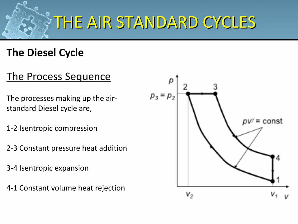
The Diesel Cycle
The Process Sequence The processes making up the air-standard Diesel cycle are, 1-2 Isentropic compression 2-3 Constant pressure heat addition 3-4 Isentropic expansion 4-1 Constant volume heat rejection

THE AIR STANDARD CYCLES
43
The Diesel Cycle Analysis Compression / expansion index under the cold air-standard assumptions
THE AIR STANDARD CYCLES
44
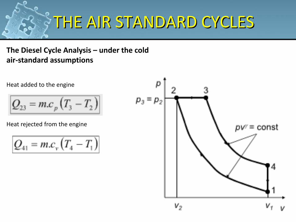
The Diesel Cycle Analysis – under the cold air-standard assumptions Heat added to the engine Heat rejected from the engine
THE AIR STANDARD CYCLES
45
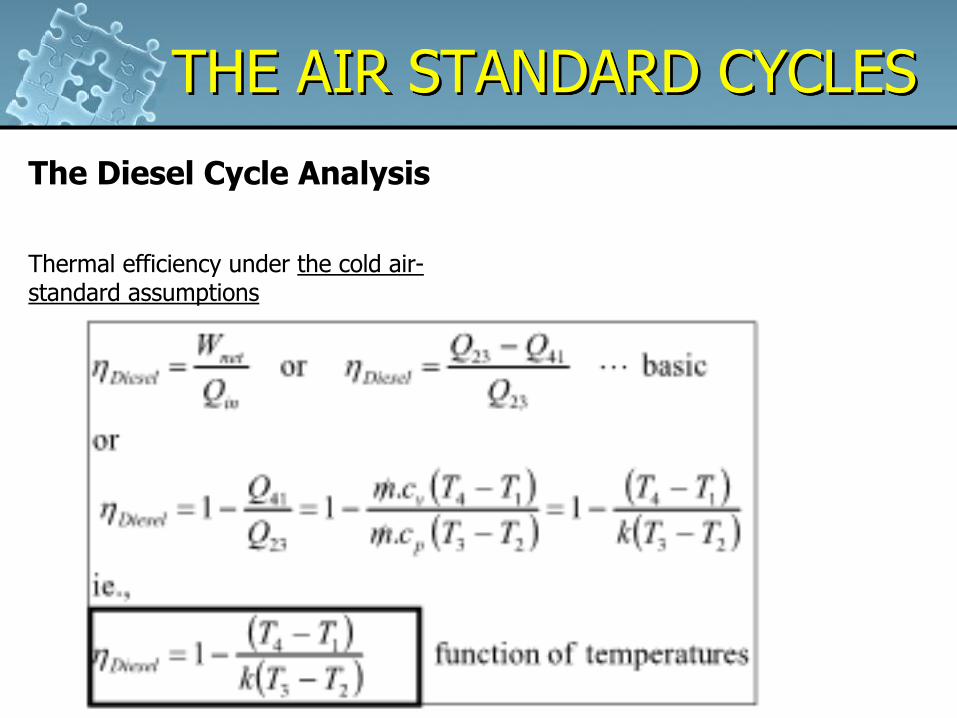
The Diesel Cycle Analysis Thermal efficiency under the cold air-standard assumptions

THE AIR STANDARD CYCLES
46
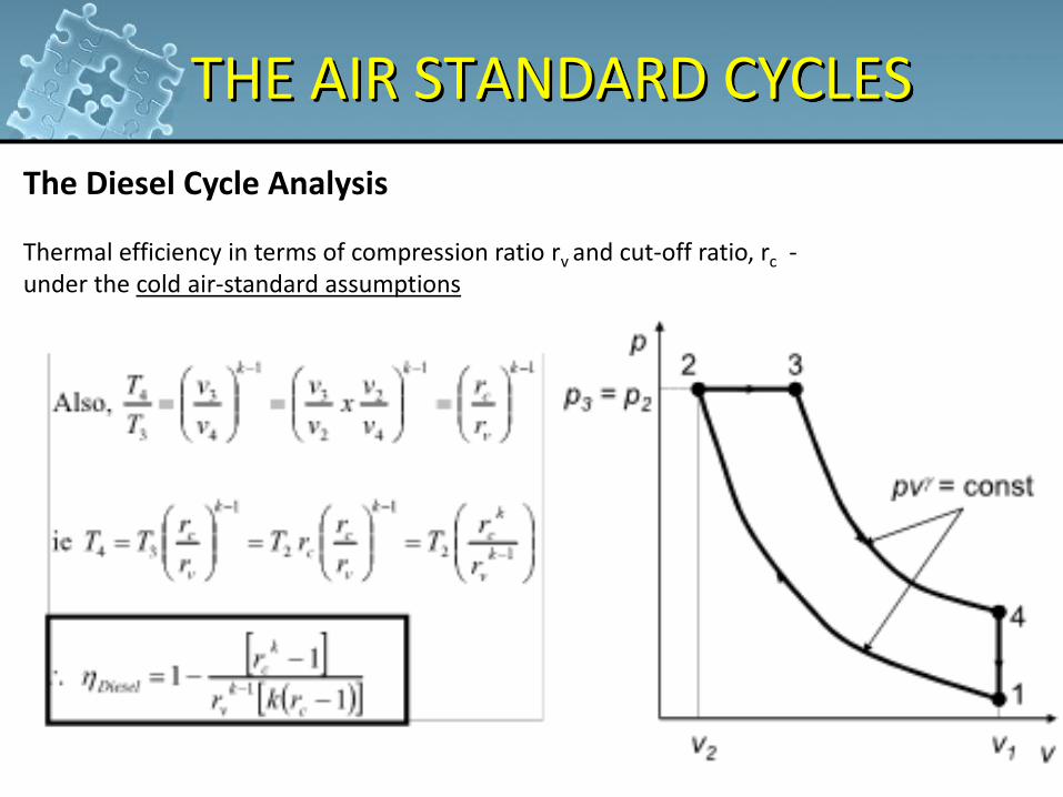
The Diesel Cycle Analysis Thermal efficiency in terms of compression ratio rv and cut-off ratio, rc - under the cold air-standard assumptions
THE AIR STANDARD CYCLES
47
The Diesel Cycle Analysis Thermal efficiency in terms of compression ratio rv and cut-off ratio, rc - under the cold air-standard assumptions
EXAMPLE
48
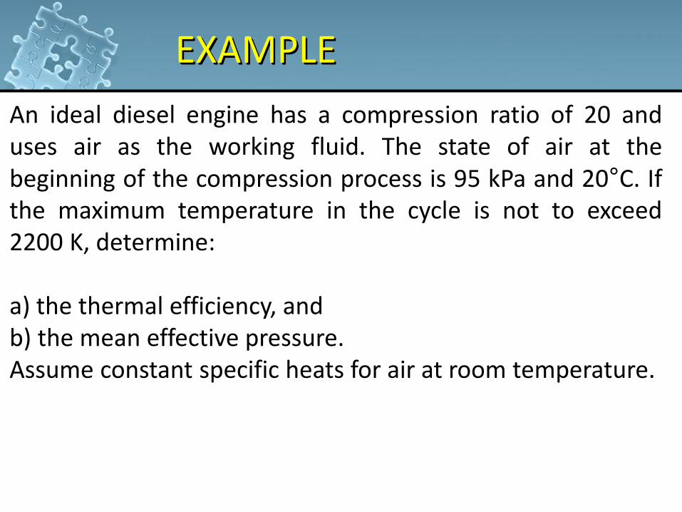
An ideal diesel engine has a compression ratio of 20 and uses air as the working fluid. The state of air at the beginning of the compression process is 95 kPa and 20°C. If the maximum temperature in the cycle is not to exceed 2200 K, determine: a) the thermal efficiency, and b) the mean effective pressure. Assume constant specific heats for air at room temperature.
EXAMPLE
49
An air-standard Diesel cycle has a compression ratio of 16 and a cutoff ratio of 2. At the beginning of the compression process, air is at 95 kPa and 27°C. Accounting for the variation of specific heats with temperature, determine: a) the temperature after the heat-addition process, b) the thermal efficiency, and c) the mean effective pressure.
50
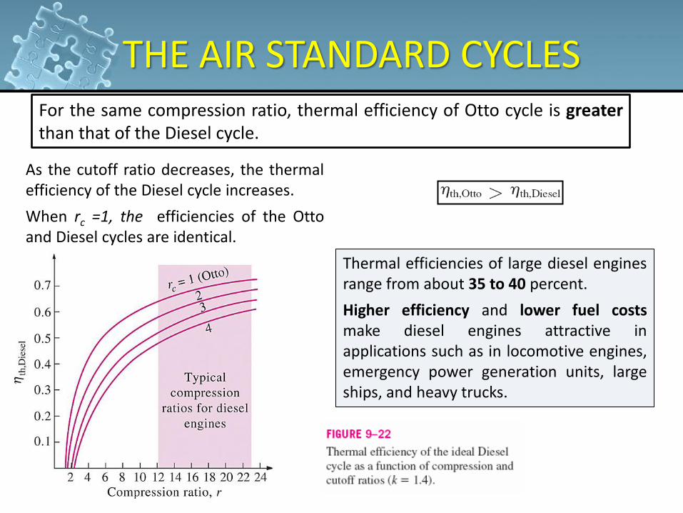
For the same compression ratio, thermal efficiency of Otto cycle is greater than that of the Diesel cycle.
As the cutoff ratio decreases, the thermal efficiency of the Diesel cycle increases.
When rc =1, the efficiencies of the Otto and Diesel cycles are identical.
Thermal efficiencies of large diesel engines range from about 35 to 40 percent.
Higher efficiency and lower fuel costs make diesel engines attractive in applications such as in locomotive engines, emergency power generation units, large ships, and heavy trucks.
THE AIR STANDARD CYCLES
THE AIR STANDARD CYCLES
51
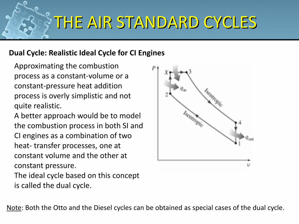
Dual Cycle: Realistic Ideal Cycle for CI Engines
Approximating the combustion process as a constant-volume or a constant-pressure heat addition process is overly simplistic and not quite realistic. A better approach would be to model the combustion process in both SI and CI engines as a combination of two heat- transfer processes, one at constant volume and the other at constant pressure. The ideal cycle based on this concept is called the dual cycle.
Note: Both the Otto and the Diesel cycles can be obtained as special cases of the dual cycle.
THE AIR STANDARD CYCLES
52
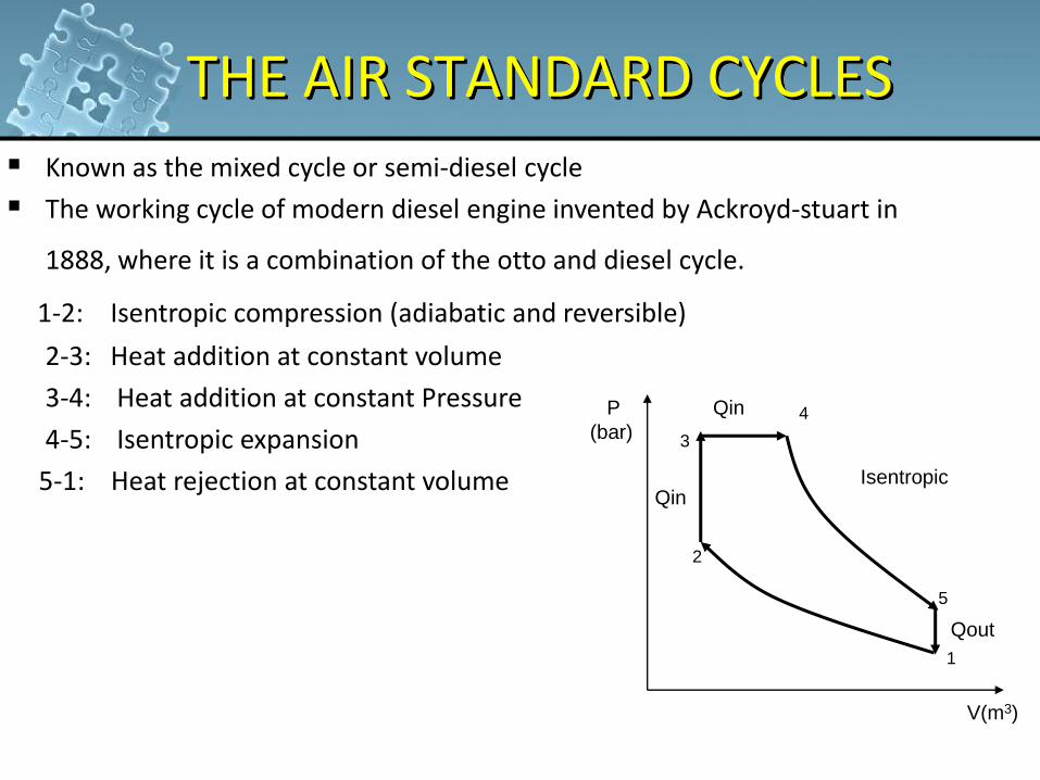
Known as the mixed cycle or semi-diesel cycle
The working cycle of modern diesel engine invented by Ackroyd-stuart in
1888, where it is a combination of the otto and diesel cycle. 1-2: Isentropic compression (adiabatic and reversible)
2-3: Heat addition at constant volume
3-4: Heat addition at constant Pressure
4-5: Isentropic expansion
5-1: Heat rejection at constant volume
1
2
3
4
5
Qin
Qin
Qout
P
(bar)
V(m3)
Isentropic
EXAMPLE
53
An air-standard Dual cycle has a compression ratio of 18 and a cutoff ratio of 1.1. The pressure ratio during constant volume heat addition process is 1.1. At the beginning of the compression process, air is at 90 kPa, 18°C and V is 0.003m3. How much power will this cycle produce when it is executed 4000 times per minutes?


