Chapter 5 Induced Radioactivity at Accelerators
96
Chapter 5 Induced Radioactivity at Accelerators In this chapter the production of induced radioactivity at accelerators is described. This discussion begins with a review of the basic principles of the production of radioactivity. It proceeds with a discussion of the activation of accelerator components including some generalizations that may be used for practical health physics applications. The chapter also considers the production of airborne radioactivity from both the standpoints of occupational and environmental radiological protection. Finally, the chapter concludes with a discussion of soil and groundwater activation pertinent to environmental protection concerns. I. Fundamental Principles of Induced Radioactivity at Accelerators In principle, induced radioactivity can be produced at all accelerators capable of liberating neutrons and other hadrons. When the accelerated beam strikes a nucleus, it converts it into a different nuclide which may be radioactive. In these discussions, the actitity of a given radionuclide refers to the number of atoms that decay per unit time. The customary unit of activity is the Curie (and its submultiples) which was originally defined to be the activity of 1 gram of natural radium but now is defined to be 3.7 X 10¹⁰ decays per second. The SI unit of activity is the Becauerel (and its multiples) which is defined to be 1 decay per second. A related quantity of considerable importance is the specific activity which is defined to be the activity per unit volume or, alternatively, the activity per unit mass. Radioactive decay is a random process characterized by a mean-life (time) denoted by r (set), and its reciprocal, the decay constant h [h = UT (see-I)]. If a total of Ntot(t) atoms of a radionuclide are present at time t, the total activity At&t) is determined by the random nature of radioactive decay to be d&,,(t) N,,(t) Atot(t) = - dt = - = AN,,(t) . r (5-l) If, at time t = 0, Ntbt(O) atoms are present, then this simple differential equation has the solution: A tot(t>= J&,,KWq-W4 = A ,,KVexp(-AtI. (5.2) Often, the time required to decay to half of the original activity is tabulated. This half-life, denoted as tin, is related to the mean-life by the following: r = j&2 = 0.;93tV2 = 1.442t,,. (5.3) The most simple activation situation at accelerators is illustrated by the constant irradiation of some material by a constant spatially uniform flux density of neutrons (or other high energy hadrons at the higher energies) that begins at some time t = 0, continues for an irradiation period that ends at t = ti, followed by a decay period called the “cooling time” and denoted tC. k is a period which begins at t = ti and ends at t = ti + tc. of the hadrons by the target is iFnore& For this simplest situation, self-absorption Also ignored is the fact that a whole spectrum page 5-l
Transcript of Chapter 5 Induced Radioactivity at Accelerators

Chapter 5 Induced Radioactivity at Accelerators
In this chapter the production of induced radioactivity at accelerators is described. This discussion begins with a review of the basic principles of the production of radioactivity. It proceeds with a discussion of the activation of accelerator components including some generalizations that may be used for practical health physics applications. The chapter also considers the production of airborne radioactivity from both the standpoints of occupational and environmental radiological protection. Finally, the chapter concludes with a discussion of soil and groundwater activation pertinent to environmental protection concerns.
I. Fundamental Principles of Induced Radioactivity at Accelerators
In principle, induced radioactivity can be produced at all accelerators capable of liberating neutrons and other hadrons. When the accelerated beam strikes a nucleus, it converts it into a different nuclide which may be radioactive. In these discussions, the actitity of a given radionuclide refers to the number of atoms that decay per unit time.
The customary unit of activity is the Curie (and its submultiples) which was originally defined to be the activity of 1 gram of natural radium but now is defined to be 3.7 X 10¹⁰ decays per second.
The SI unit of activity is the Becauerel (and its multiples) which is defined to be 1 decay per second.
A related quantity of considerable importance is the specific activity which is defined to be the activity per unit volume or, alternatively, the activity per unit mass.
Radioactive decay is a random process characterized by a mean-life (time) denoted by r (set), and its reciprocal, the decay constant h [h = UT (see-I)]. If a total of Ntot(t) atoms of a radionuclide are present at time t, the total activity At&t) is determined by the random nature of radioactive decay to be
d&,,(t) N,,(t) Atot(t) = - dt = - = AN,,(t) .
r (5-l)
If, at time t = 0, Ntbt(O) atoms are present, then this simple differential equation has the solution:
A tot(t> = J&,,KWq-W4 = A ,,KVexp(-AtI . (5.2)
Often, the time required to decay to half of the original activity is tabulated. This half-life, denoted as tin, is related to the mean-life by the following:
r = j&2 = 0.;93tV2 = 1.442t,,. (5.3)
The most simple activation situation at accelerators is illustrated by the constant irradiation of some material by a constant spatially uniform flux density of neutrons (or other high energy hadrons at the higher energies) that begins at some time t = 0, continues for an irradiation period that ends at t = ti, followed by a decay period called the “cooling time” and denoted tC. k is a period which begins at t = ti and ends at t = ti + tc. of the hadrons by the target is iFnore&
For this simplest situation, self-absorption Also ignored is the fact that a whole spectrum
page 5-l

Chauter 5 Induced Radioactivitv at Accelerators
of neutrons might be present. Thus the process of producin by a single cross section, CJ [cm2 or barns (1 barn = 5 lo-24 cm
the radioactivity is characterized )] which, in the more complicated
generalized situations could be an appropriate averape cross section.
The number of atoms of the radionuclide of interest per unit volume will thus be governed b,y the following differential equation during the period of the irradiation:
dn(t) - = -An(t)+ No+,
dt (5.4)
where n(t) is the atoms of the radionuclide per cm3 at time t. N is the number of “target” atoms per cm3, 0 is in units of cm2, and $I is the flux density (cm-2 set-l) of incident particles. N is defined in chapter 1 immediately following J5q. (1.6). On the right hand side of the above equation, the first term represents the loss of radionuclides through decay during the irradiat:ion while the second term represents the gain of radionuclides through the production reaction under consideration.
The equation has the following solution for 0 < t < ti;
n(t) = !!f?(l -e-it). (5.5)
Thus the snecific activitv (B 1
/cm3) induced in the material as a function of time during the irradiation is given by a(t) = n(t), hence
a(t) = Na$(l-e-‘) for O<t < ti. (5.6)
[To obtain specific activity in Curies/cm3, one must simply divide by the constant 3.7 X lOlo Curies/Bq.]
At the instant of completion of the irradiation (t = ti) , the specific activity will thus be:
a(4) = N@[ I- exp(-Ati)] , (5.7)
so that we see that the specific activity as a function of time is characterized by a buildup from zero to the saturation value of Na$ for infinitely long irradiations.
After the irradiation has ceased (t > ti), the specific activity as a function of the “cooling time”, tc, will obviously decay exponentially and be given by:
a&) = NW1 -exp(-hti)]exp(-ht,} (5.8)
where k is the cooling time; k = t - ti. (5.9)
For total activities in situations where uniform flux densities of particles of constant energy a.re incident on a homogeneous “target”, one can simply multiply by the volume of the “target”; or in more complex cases involving nonuniform flux densities, integrate the above over the volume of the target.
page 5-2

Chapter 5 Induced Radioactivity at Accelerators
For y-ray emitters, the absorbed dose rate, dD/dt (rad/h), at a distance r (meters) from a “point” source of typical activation y-rays (those in the range from about 100 keV to 10 MeV) is given in terms of the source strength, S, (Ci), and the photon energy, Ey (MeV) by:
z = 0.4xEyi i
(5.10)
where the summation is over all y-rays present, including appropriate branching fractions if rnore than one photon is emitted per decay. If dD/dt is desired as an approximate absorbed dose rate in Gy/h at a distance, r (meters), from a source strength S in GBq (GBq, 109 Bq, is a more practical unit than is Bq), the factor 0.4 becomes 1.08 X lOA. Thus one can use the above to determine the absorbed dose rate from a given activated object if it is a point source. For non- point sources, an appropriate spatial integration must be performed.
page 5-3

Chapter 5 Induced Radioactivity at Accelerators
II. Activation of Accelerator Components [Parts of this discussion follow that of (NC96)]
Proton accelerators whose energy exceeds about 10 MeV will produce radioactivity. This will also occur for accelerators of other ions above a specific energy of about 10 MeV/amu. In some special cases radioactivity can be produced at much lower energies because of exothermic nuclear reactions which either produce radionuclides directly or emit neutrons capable of inducing radioactivity through their secondary interactions. If a given accelerator is properly designed with respect to the shielding against prompt radiation and has proper access controls to avoid direct beam-on exposure to people, the induced radioactivity is very likely to be the dominant source of exposure to people. In fact, the experience at most accelerators bears this out in that the vast majority of the radiation exposure incurred by the workers is due to maintenance activities on radioactivated components, handling and moving of activated items, radiation surveys, and radioactive waste handling. An understanding of the production of radionuclides can help reduce personnel exposures through the selection of more appropriate machine component materials and the optimization of decay (“cool-down”) times recommended after the beam has been turned off.
The primary focus of this section is on proton accelerators because the activation is much more severe at such machines. Marcel Barbier (Ba69) has rather adequately handled activation by photons and electrons and also considered special problems associated with heavy ions.
For the lower incident energies (< 30 MeV), one is first concerned with production of radionuclides by such processes as (p,y) and single- and multi-nucleon transfer reactions. While the details of the total cross sections for such reactions continue to form an interesting subfield of nuclear physics, the systematics and annroximate energy dependencies are globally well understood. In general, one is dealing with endothermic nuclear reactions which have a threshold, Eur. below which the process is forbidden by conservation of energy. For nuclear reactions induced by ions, Etl., is related through masses of the projectile, m, and the target, M, to the energy released in the reaction, (the reaction “Q value”, see discussion in Chapter 1) Qv, by :
m+M Eth=+Q"l~ where the Qv is negative in an endothermic reaction having a positive value of E~J-,. In this equation, m is the mass of the incident projectile while M is the mass of the target atom, assumed to stationary. Thick target yields of radionuclides for targets having a range of atomic numbers have been systematically plotted for numerous reaction processes by B. L. Cohen (Co78). Representative plots for the more significant reactions are given in Fig. 5.1 taken from (Co78). It is assumed that the target thickness comfortably exceeds the range of the incident ion and that the irradiation period greatly exceeds the half-life of the radionuclide of interest. If shorter bombarding periods are used, one can correct by multiplying the plotted value by the factor I:1 - exp(-hti)]. The values of @@A (microCuries per targeted microamperes of beam current) should be accurate to within a factor of about three.
It should be emphasized that these are plots of radionuclide yield as a function of the energy above threshold, E - Eth. As one can see, a general feature is that the yield rises as the threshold energy is exceeded by the bombarding energy by a few MeV. At higher energies, the rate of increase of yield with energy rises more slowly and, in some cases, appears to level off to a “saturation” value. Over the energy range of these curves, the importance of activation by secondary particles is small compared to that encountered at higher energies.
page 5-4

Chapter 5 Induced Radioactivity at Accelerators
c
-a
,I0 - t
Y W
t 4
E
1 page 5-5

Chapter 5 Induced Radioactivity at Accelerators
p’ --
‘-8
P
i‘ E
I I I
p 5 ‘0
P
Y
5
f Y
?
-R
,(D - c G ?,
i’ ” I I
5 I a a <
* a
$ w P ”
w
- I I I I I
35 35 P P 5 5 P P . . . .
I!
B f Y
0- c
P
5 a
page 5-6

Chapter 5 Induced Radioactivity at Accelerators
For particle accelerators of higher energy, the neglect of secondary reactions and the restriction to few- and multi-nucleon transfer reactions can become a serious deficiency in the accuracy of estimation of induced radioactivity because of the rise in importance of such processes as spallation. Fig. 5.2 taken from (Pa73) illustrates how the number of radionuclides produced increases with increased bombarding energy for the case of protons incident on bismuth. At .40 MeV, only few-nucleon transfer reactions are available while at 3 GeV, essentially the entire periodic table of nuclides having mass numbers less than that of the target material becomes available. The “bipolar” peak obtained at 480 MeV clearly represents the optimization of the fission process. The variety of radionuclides that can be produced increases as one increases the bombarding energy because more thresholds are exceeded. As a general rule, at high energ-ies CEO = 1 GeV or greater), one must consider that&l radionuclides in the periodic table which have mass numbers less than that of the material exposed to the flux of hadrons may be produced. Of course, many of these are of little significance due to short lifetimes and small production cross sections.
t
100 7
g IOF
I; -
I-
XBL717-1173 XBL717-1173
Fig. 5.2 Mass yield curves for the proton bombardment of bismuth for various energies. [Reproducti from (Pa73) as adapted from references cited therein.]
page 5-7

Chapter 5 Induced Radioactivity at Accelerators
Table 5.1 taken from (NC96) gives a list radionuclides typically encountered in accelerator installations and their half-lives. In this table only nuclides with half-lives between 10 minuxx and 5 years are listed. Also, all “pure” (that is, with no ‘y-ray emitted ) p emitters are ignored.
Table 5.1 Summary of radionuclides commonly identified in materials irradiated around accelerators.
Target material
Plastics and oils
DUdtUllitl
Radionuclidcs
‘BC
11C
As above, plus
BNa %Na
Half-life
53.6 days
20.4 minutes
2.60 years 15.0 hours
Steel As above, plus 42K 43K “SC amsc 4% 4% 49c 48V 5’cr %4n 5hMn wurl
StaiIlltss steel As above, plus
57Ni
As above, plus mi wu 6kl.l %J wn ~Qn
12.47 hours 22.4 hours 3.92 hours 2.44 days 84 days 3.43 days 1.83 days 16.0 days 27.8 days 5.55 days 21.3 minutes 300 days 77 days 270 days 72 days 2.94 years 45.1 days
5.27 years 37 hours 24 minutes
2.56 hours 3.33 hours 9.80 minutes 12.82 hours 38.3 minutes 245 days
page S-8

Chauter 5 Induced Radioactivitv at Accelerators
An extensive treatise on induced activity, dealing with the multitude of complications has been written by Barbier (Ba69) in which methods for systematizing the large body of nuclear physics data are described. The reader is encouraged to refer to this reference for an extensive discussion of the mechanisms, including many excitation functions for many nuclides of interest.
Concerning the activation of accelerator components, one must have a systematic way of handling the great multiplicity of radionuclides produced, as illustrated above, since it is simply not practical to handle them all separately. Global properties of the distribution of radionuclrdes must be used. Sullivan and Overton (Su65) have treated this problem in an elegant manner which will now be restated here. The initial starting point is an equation of the form derived previously for describing activity, but now related to dose rate (which is, of course, proportional to activity):
S(t,,t,) = GQ[ 1 - exp(-htJlexp{-UtJ 1, (5.12)
where S(Ti,tc) is the absorbed dose rate, $ is the flux density, and G is a collection of many contributmg factors from among the following:
production cross section energy of the beam types of secondaries produced isotopic composition of the irradiated component geometry energy of the y-rays produced attenuation coefficients for the y-rays produced.
If the number of radionuclides produced by the irradiation which have decay constants in the interval between h and h + dh is re
% resented by the differential dm, then the corresponding
increment in absorbed dose rate, d (ti, t& is given by:
dS(ti, tJ = G$[ I- exp(-htJ]exp{-X(t,))dm . (5.13)
If it is assumed that the value of G is independent of h, or its dependence on h is small compared to other factors, then one can integrate’ :
S(ti, tJ = GQ I m dk$f[ 1 - exp(--htJ]exp{ -ii(t ~ 0 (5.14)
Here, &, is the shortest decay constant (longest mean-life) to be considered. Barbier (Ba69) has followed up on the work of Sullivan and Overton and has plotted the distributions of isotopes with respect to their half-lives below a given atomic mass as shown in Fig. 5.3. (This, then, corresponds to the distribution of isotopes that could be produced in a target of mass number A irradiated by high energy hadrons.) Figures 5.4 and 5.5 taken from (Ba69) show the integrals of these distributions up to a given value of half-life.
‘This implicitly makes the assumption that, on average, the cross sections that produce the radionuclides of concern are indepndent of both the half-lives and the particle energies. Somewhat remarkably, this approximation is sufficiently accurate.
page 5-9

Chapter 5 Induced Radioactivitv at Accelerators
-AA*209 -AA*209 - - A4101 A4101 - - A< A< 60 60 - - Ac Ac 25 25
Fig. 5.3 Distribution of radioactive isotopes below a given atomic number with respect to their half lives. (Ba691.1
[Reproduced from

Chapter 5 Induced Radioactivity at Accelerators
z 8 0 8
.
page 5-11

Chapter 5 Induced Radioactivity at Accelerators
Sullivan and Overton (Su65), also as discussed in (Ba69), found that these cumulative distributions are well-described for values of half-life between 10-j and 103 days by the following form:
N (tl12> = a + b In (ttn), (5.15)
where N (tin) is the number of isotopes with half-lives less than the value of t1/2 and a and b are fitting parameters. Because of the one-to-one cotrespondance between values of t1/2, r, and IL, one can just as well write
m(A) = a+ b lnh, (5.16)
where m(h) is the number of radionuclides with decay constants greater than h for the material of concern. Thus,
dm @I dh
= f. (5.17)
Substituting into JZq. (5.14), one gets:
S(ti,t3 = Gb~ I
m *[l - eXp(-hti)]eXp{-h(Q) _
A h 0
= Gw I
m di;f2Xp(-l.(ti + tJ) h h . (5.18)
0
The changes of variables a = ht, (first term) and a’ = h(ti + k) are helpful;
S(ti, tc) = Gb da’s (5.19)
Recognizing that the integrands are identical and simplifying by rearranging the limits of integration, we have
da$. (5.20)
The integral is of a form that integrates to a series expansion found in standard tables of integrals;
s
X2 eaxdx ln x + ax + aZx2 a3x3 1 X2 - =
X l! Xl
2(2!) + 3(3!) + ... x1’ (5.21)
page 5-12

Chapter 5 Induced Radioactivity at Accelerators
Substituting,
I A,($ + tc)
e-ads a
htc
= In a -la + $ - $ + . . . 1 &Ott, + tc)
UC . (5.22)
Evaluating, one obtains
6(ti, tc) = Gb (5.23)
Since & approaches zero (corresponding to large lifetimes), the following is obtained:
6(ti,t3 = B$ In (5.24)
where several constants are merged in parameter B.
Peter Gollon (Go76) has further elaborated on these principles and determined some very useful “rules of thumb” for high energy hadron accelerators at which the extranuclear hadron cascade process produces the major fraction of the induced activity. Four rules are extremely useful for approximate radioactivity estimates:
Rule I (Repeated here for convenience) The absorbed dose rate, dD/dt (rad/h), at a distance r (meters) from a “point” source of typical activation y-rays is given in terms of the source strength (Ci) and the photon energy, Eu (MeV) by:
$ = 0.4xEyi ; ,
0 L
i
(5.25)
where the summation is over all y-rays present, including appropriate branching fractions if more than one photon is emitted per decay. If dD/dt is desired as an approximate absorbed dose rate in Gy/h at a distance r (meters) from a source strength S in GBq, the factor 0.4 becomes 1.08 X lOA.
Rule 2: In many common materials, about 50 % of the nuclear interactions produce a nuclide with a half-life longer than a few minutes. Further, about 50 % of these have a half-life longer than one day. Thus approximately 25 % of the nuclear interactions (e.g., the “stars” discussed in Chapter 3) produce a radionuclide having a half-life exceeding approximately one day.
Rule 3: For most common shielding materials, the approximate dose rate dD/dt due to a constant irradiation is given as above:
dD(t3 - = B$ln
d t c (5.26)
page 5 13

Chapter 5 Induced Radioactivity at Accelerators
In the above, the geometry and material dependent factor B can often be determined empirically, or by using rule 2, while @ is the incident flux density. This expression appears to be valid also for heavy ion beams at 86 MeV/nucleon according to Tuyn (Tu84).
Rule 4: In a hadronic cascade, a proton produces about four inelastic interactions for each GeV of energy.
These rules can be illustrated by examples. In a short target, l/10 of an interaction length long, approximately 10 % of an incident beam of 1011 protons s-l will interact. Assume this has been occurring for several months (long enough to reach saturation production for many radionuclides). Using Rule 2 in conjunction with the above rate, one determines that the decay rate after one day of the shutdown is 2.5 X 10⁹ Bq (68 mCi). If each of these decays produces a 1 MeV y-ray , then Rule 1 will indicate an absorbed dose rate of 27 mrad/h (= 0.27 mGy/h of absorbed dose rate) at one meter away.
Rule 3 can be used along with such a calculation to predict the absorbed dose rate from a point source at some future time after beam shutdown . Furthermore, this rule is not restricted to “point” sources but can be used for more massive ones, with suitable adjustments to the geometry factors. Sometimes one can estimate the product B$ or use a measurement of the exposure or absorbed dose rate to determine it empirically for the purpose of using the formula to predict the “cooldown”. In this way, Rule 3 is also useful for extended shields irradiated by secondary particles from a well-developed cascade. Rule 4 can be used to crudely estimate the activation of a beam dump by incident high energy particles when it is coupled with Rule 2.
Rule 4 can be used thus: A beam of 1012 400 GeV p/s (= 0.16 PA or 64 kW) produces a total of 4 X 400 X 1012 stars/s in a beam dump. If 25 % of these produce a radionuclide with a half-life > 1 day (rule 2), then the total amount of the moderately long-lived radioactivity (at saturation) is:
(0.25 atoms/star)(l.6 X 1015 stars/set) = los8 kCi
3.7 X 10” s-Q-’ (5.27)
At sufficiently large distance (say 10 meters), rule 1 could be used to calculate an absorbed dose rate assuming all decays are 1 MeV y-rays:
z = 0.4(1 MeV)( l’“~~~~~es) = 43rads/hour. (5.28)
A valuable parameter used to quantify the absorbed dose rate, dD/dt, at the surface of a thick target is the danger parameter, D, as developed by Barbier (Ba69) for a thick object irradiated by beam with a uniform flux density 9. If this source of radioactivity subtends solid angle R at the point of concern, then
(5.29)
page 5-14

Chapter 5 Induced Radioactivity at Accelerators
F 4
0 ‘1 1 I , l,,,, , , , I,, 0 1 P
62 JE ‘0 ‘; P
e
Fig. 5.6 Values of the Barbier Danger Parameter. [Reproduced from (Ba69).]
page 5-15

Chapter 5 Induced Radioactivity at Accelerators
ry F’ ’ ’ ““” ’ ’ - I”” - - ’ ‘““” - ’
Fig. 5.6 Values of the Barbier Danger Parameter. [Reproduced from (BaN).]
page S-16

Chapter 5 Induced Radioactivity at Accelerators
5
YI I”“1 ’ ’ ’ I”” I ’ ’ _
oyj I 3 %
\
c ‘: “0
a m
1;s 0 8 b CI
,z LL,-
ti
-9 r -
%: L
1: 1 v
PI c ‘0 b
Y f - ’ * r-*.l. - - I-.-’ ’ - f--xl 1 - 1 2 . , 1
Fig. 5.6 Values of the Barbier Danger Parameter. [Reproduced from (Ba69).]
page 5-17

Chapter 5 Induced Radioactivity at Accelerators
4 F”’ ’ ’ r ““.” ’ ’ ““” ’ ’ ’ I”“’ ’ ’ . A
8: z 81 n
r /y
b
0 1. 1 1 LQ---+--ltl~ ’ % = , ‘: b 9 9
m \. - m I..., Y pi - 2
z 1
1 t
1”
.‘,a; s: ti %: Br I 8:
0
‘1
I- I . I .,,I 1. I . ,....,. . .
= lp b b
* “b
b
Fig. 5.6 Values of the Barbier Danger Parameter. [Reproduced from (Ba69j.l
page 5-18

Chapter 5 Induced Radioactivity at Accelerators
Fig. 5.6 Values of the Barbier Danger Pammeter. [Reproduced from (Ba69).]
page 5-19

Chapter 5 Induced Radioactivity at Accelerators
For contact with a semi-infinite slab of uniformlv irradiated material, the fractional solid angle factor (R/4x) has the intuitively obvious value of l/2. The danger parameter D has the physical interpretation as the absorbed dose rate found inside a cavity of arbitrary form embedded in an infinite volume of a material which has been uniformly irradiated by a unit flux density (one particle per second per square centimeter). Figures 5.6 taken from (Ba69) give representative examples of plots of D for several elements and a few compounds. These curves thus can be used to predict cooling of various components around accelerators.
Gollon (Go76) provided “cooling curves” for iron struck by high energy protons. These are given in Fig. 5.7 taken from (Go76)and include both calculations by Armstrong and Alsmiller (Ar’73) and empirical measurements at the Brookhaven National Laboratory AGS, the Fermilab Main Ring Accelerator, and the Fermilab Neutrino target “train”.
I 1 1 1 ,,I,, 1 1 11.1111 1 I 1 I .llll L I 1 II 11.1 1 rrr-
lo-! ‘OS ‘0; IO2 IO' IO'
TIME AFTER SHUTDOWN (hr 1
Fig. 5.7 Cooling curves for various irradiation times for iron struck by high energy protons as calculated by Armstrong and Alsmiller (Ar73). Also shown are measured curves. The one labeled “ACCEL”, is the meawred average cooling curve for the Fermilab Main Ring syncbrotron after its initial three years of operation. Tbe curve labeled “NEUTRINO” is for a neutrino target train at Fermilab after eight months of operation. The curve labeled “AGS” is for an extraction splitter in use for many years at the BNL AGS. [Reproduced from (Go76).]
Of course, one is often concerned with situations where the determination of “$” in the danger parameter equation is not at all simple. For example, one can have activation in a large object where the hadronic cascade is contributing numerous hadrons at a variety of energies from a multitude of directions. Fortunately, important features of activation phenomena have little or no correlation with energy. The chief of these is evidenced by the excitation functions of various reactions. In general, the cross sections rise just above the threshold and then, somewhere in the region of 10’s of MeV, a leveling-off occurs. Furthermore, in general the cross sections for production of radionuclides by neutrons and protons (and even other ions and particles) do not differ from each other at the higher energies. Results from Barbier’s book (Ba69) illustrate this and are given as Fig. 5.8.
page S-20

Chanter 5 Induced Radioactivitv at Accelerators
1 l,...l.* I I.... I . . I
bl9 t 0
Fig. 5.8 Curves of excitation
L 9 2 6 6 3 .a
P F
functions for nuclear reactions. [Reproduced from (Ba69).)
page 5-21

Chapter 5 Induced Radioactivity at Accelerators
B Robctiandisdcpuhhbypdas
i/l 1
A
1, ’ - ’ * ” ‘. ’ 1 ” 1 I - I * I. 1. I. I -
B ,Robctiandisdcpuhhbypdas
1 Fl \
;; j
x4i,,j,b ,,,,,.
1
L: II
vu
m 4
0 0 10 Jo 40 m 0 Tow 0 0 10 Jo 40 m 0 Tow
k,,m,,,~,,,,,~,
q.h&db d i-in& by m.
WTT!
w
1
! i!
“r”‘a ““I ’ p9
Fig. 5.8 Curves of excitation functions for nuclear reactions. [Reproduced from (Ba69).]
page 5-22

Chapter 5 Induced Radioactivity at Accelerators
R &-
UJ
I . . ..I I I I 1,111 I I 1 1 t 2 1. I--‘ ‘- E
‘1 . f$ii
-[ i I,~, liil ,“.. , I 1 . ,““I .
Fig. 5.8 Curves of excitation functions for nuclear reactions. [Reproduced from (Ba69).]
page 5-23
Chapter 5 Induced Radioactivity at Accelerators
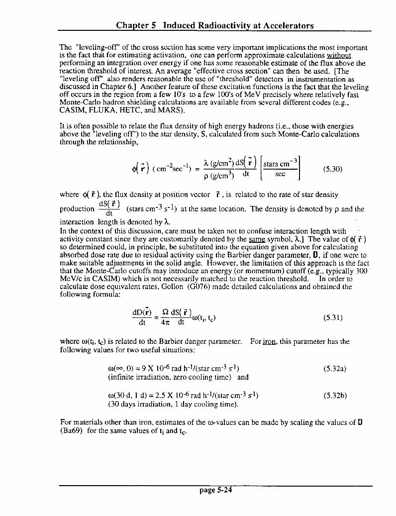
The “leveling-off’ of the cross section has some very important implications the most important is the fact that for estimating activation, one can perform approximate calculations without performing an integration over energy if one has some reasonable estimate of the flux above the reaction threshold of interest. An average “effective cross section” can then be used. [The “leveling off” also renders reasonable the use of “threshold” detectors in instrumentation as discussed in Chapter 6.1 Another feature of these excitation functions is the fact that the leveling off occurs in the region from a few 10’s to a few 100’s of MeV precisely where relatively fast Monte-Carlo hadron shielding calculations are available from several different codes (e.g., CASIM, FLUKA, HETC, and MARS).
It is often possible to relate the flux density of high energy hadrons (i.e., those with energies above the “leveling off’) to the star density, S, calculated from such Monte-Carlo calculations through the relationship,
d 1 h (g/cm’)dS( ;) stars cm -3
3 ( cm-*set-‘) = p C&m31 dt [ 1 set
(5.30)
where Q( Z ), the flux density at position vector ‘r , is related to the rate of star density dS( “r )
production 7 (stars cm-3 s-l) at the same location. The density is denoted by p and the
interaction length is denoted by h. In the context of this discussion, care must be taken not to confuse interaction length with activity constant since they are customarily denoted by the fame symbol, x.1 The value of Q( ? ) so determined could, in principle, be substituted into the equation given above for calculating absorbed dose rate due to residual activity using the Barbier danger parameter, 0, if one were to make suitable adjustments in the solid angle. However, the limitation of this approach is the fact that the Monte-Carlo cutoffs may introduce an energy (or momentum) cutoff (e.g., typically ,300 MeV/c in CASIM) which is not necessarily matched to the reaction threshold. In order to calculate dose equivalent rates, Gollon (G076) made detailed calculations and obtained the following formula:
dD(;) R dS( ‘: ) - = 4xdtNtiv tJ dt
(5.3 1)
where O(ti, k) is related to the Barbier danger parameter. For ti, this parameter has the following values for two useful situations:
~(00, 0) = 9 X 10-e rad h-*/(star cm-3 sl) (infinite irradiation, zero cooling time) and
(5.32a)
~(30 d, 1 d) = 2.5 X lo-6 rad h-*/(star cm-3 ~1) (30 days irradiation, 1 day cooling time).
(5.32b)
For materials other than iron, estimates of the o-values can be made by scaling the values of D (Ba69) for the same values of ti and tc.
page 5-24

Chapter 5 Induced Radioactivity at Accelerators
Finally, Gollon derived a simple relationship between dose rates involving cooling times different from “standard” ones for which values of 0 and o are available. the dose rate after irradiation time ti and cooldown time tc is
As stated previously,
&tivtJ = F A& 1 - exp(-hptJ]exp( -h,(t,>) (5.33)
where the summation over index lo includes all relevant radionuclides and the product of flux density and geometry factors are absorbed (and allowed to vary with radionuclide) in the quantity
AP*
Rearranging, Gollon obtained:
&ti,tJ = C A P
#XP { -QCt,J } - eXP{ -J-,(ti+ L)}]
= 6(m, tc) - 6(O”y ti + tc). (5.34)
Thus, the infinite irradiation curve can be used to determine u other combination of the times ti and tc. In fact, this formula is exact, it is “model independent” and may be used also with empirical results such as, for example, radiation survey data.
A final method for connecting the production of “stars” in material (e.g., as calculated by a Monte-Carlo code) to the production of atoms of some radionuclide is by the ratios of cross sections. Thus, at some point in space, i, the rate of production of atoms per cm3, n(i), of some radionuclide is approximately given by:
dn(?) or dS( i) xr dS( i) dt =sdt=G dt
(5.35)
where one essentially scales the star density production rate [e.g., stars/(cmJ-s)] by the ratio of the production (reaction) cross section for the nuclide of interest, or, to the total inelastic cross cross section bin or, alternatively, by the macroscopic cross section ratio (&/&J. At saturation, this will be the rate of decay as well. The phenomena will obey the usual activation equation. The reason this is annroximate is due to the standard concerns about constancy of cross sections, lack of perfect “matching” of thresholds, etc.
Somewhat special considerations may apply to the concrete shielding surrounding accelerators. As was seen before, ordinary concrete typically contains a partial density of 0.04 g/cm3 of Na. This “typical” value varies a great deal due to the variety of minerals which might be present in local concrete. The significance of this seemingly small additive is that the naturally dominant isotope present is 23Na. This nucleus has the relatively large thermal neutron capture cross section of 535 mb.
Patterson (Pa58) determined that average thermal flux density, Qh, in a concrete room is approximately given as follows:
page S-25

Chapter 5 Induced Radioactivity at Accelerators
where Q is the number of fast neutrons produced per second in the enclosure and S is the inside surface area of the enclosure (cm*). Thus, a substantial flux density of thermal neutrons can be present in an accelerator room and this flux can produce significant amount of *4Na with its 1.5 hour half-life. The relatively high energy photon emitted in its decay ( 2.75 MeV) also can enhance the radiation hazard.
Furthermore, while the dose due to activated components falls off radially with distance, if absorption by the air is not significant, the absorbed dose rate due to residual activation in an empty cylindrical room uniformly irradiated by such thermal neutrons is a constant and the dose equivalent rate anywhere inside the enclosure will be equal to the dose equivalent at the wall.
This has been explicitly demonstrated for cylinders by Armstrong and Barish (Ar69) and is also true for the interior of u mathematically well-behaved closed surfaces. This fact can readily be demonstrated by analogy to the Gauss Law in electrostatics as follows by examining the situation in Fig. 5.9. Consider a simple, closedsurface which emits an omnidirectional flux
density of some particle $. (e.g., particles cm-2s-1) that is constant over the surface. One wants to calculate the flux density at some point in space P within the survace. P is located at radius
vector T. Consider further the contributions of the particle emitted by some elemental area
dx at P where dA is perpendicular to the surface at coordinate vector ;.
Fig. 5.9 Geometry for deriving relationship between a surface of uniform emission and the flux density at any point within it.
The solid angle subtended at P by dx is;
&--J= d&ii
I I 2-y
2 (5.37)

Chapter 5 Induced Radioactivity at Accelerators
where the unit vector i is given by
A ;-; n=-
I I ;-;
(5.38)
and is along the direction of 2 - 7 .
But the increment of flux at point P due to elemental area dx is given by:
d$ = t&,d;i.; $0
4x17-;I 2 thusd$=41cdRand
(5.39)
In some cases it has been important to minimize the amount of sodium in the concrete ingredients in order to reduce exposures to mainenance personnel. In fact, the phenomena described above has been noticed at accelerators and sometimes leads to “disappointment” in. how little gamma-ray exposure rates are reduced when “hot” components are removed from _ enclosures with equally “hot” walls. For example, Armstrong and Barish (Ar69) have calculated residual dose rates inside a cylindrical accelerator tunnel due to both the magnets and the concrete walls for 3 GeV protons incident on iron. [These authors have also included some other reactions which are capable of also producing 24Na (spallation) which also must be included.] The results are shown in Fig. 5.10 taken from (Pa73) adapted from (Ar69) for the surface at the tunnel wall.
to-6
72 =:
E <
g .; eg
a2
w,;
Ei ‘2
E .E -10 g k 10
Q;;
f ?!
Y
4 0-”
t
1 / ! I / ijjji::,
16
OREL-&‘IG G9- 5937
FROM OTHER RADIONUCLIDES I IN CONCRETE I IRI
1 I1 III/ I / 1
/ij I
.-.
CO” IO’ co’ to’ TIME AFTER SHUTDOWN (h )
Fig. 5.10 Photon dose rate at surface of tunnel wall after infinite irradiation time for concrete containing one per cent sodium by weight. [Reproduced from (Pa73) as adapted from (Ar69).]
page 5-27

Chapter 5 Induced Radioactivity at Accelerators
III. Production and Propagation of Airborne Radioactivity
Production of Airborne Radioactivity
Thomas and Stevenson have presented a very useful synopsis of the production of activity in the atmosphere in (Th88) which is largely followed here. Some of this same discussion appears in (SwgO).The principal source of radioactivity in air at accelerators is due to the interaction of primary and secondary particles directly with the constituent target nuclei in the air in accelerator enclosures. Activated dust and gaseous emission from activated liquids are of secondary importance. One must be reminded of the isotopic composition of the atmosphere and this is given in Table 5.2 taken from (Th88).
Table 5.2 Most Abundant Isotopes in the Atmosphere
Isotope _ Percentage by volume
in the atmosphere
14N 78.1
I60 21.2
@Ar 0.46
‘jN 0.28
I80 0.04
Since low energy accelerators contain their beams in continuous vacuum pipes, the activation of air at these machines is greatly minimized. At high energy accelerators, it is quite common to have air gaps at certain “interface points” and where complicated “gadgets” associated with beam targetry or beamline instrumentation render continuous vacuum impractical. (These “air gaps” are only characteristic of extracted beam lines, the machines themselves n, in general, contained in continuous vacuum.) In addition, the large multiplicity of secondary particles produced as a part of cascade (both electromagnetic and hadronic) processes can airborne radioactivity even where the beams themselves are contained in vacuum.
produce
Table 5.3 taken from (Sw90) gives the radionuclides that can be produced from the principle constituents in air along with the reaction mechanisms associated with their production and an estimate of the average production cross section. The large cross section for neutron induced (n, 7) and (n,p) reactions are for captures of thermal, E, = 0.025 eV, neutrons while the remaining cross sections can be anticipated to be the saturation cross sections found in the 10s of MeV region and above. The y-induced reactions are present at virtually all accelerators and most energies. In this table “spallation” reactions refer to the intermediate energy process by which the target nucleus is effectively shattered into a number of its constituents.
If the accelerator enclosures were completely sealed, there would be no releases to the outside world and the hazard of these airborne radionuclides would be entirely restricted to those who might have to enter the enclosures. This would, however, allow the longer-lived radionuclides to build up in accord with the activation formula. Also, ventilation is generally needed to provide cooling of components and fresh breathing air for workers. Typically, the “residence time” of air in accelerator enclosures is 30 minutes to one hour and not much longer.
page 5-28

Chapter 5 Induced Radioactivity at Accelerators
Thus, the typical half-lives of the accelerator environment “in equilibrium” will have half-lives only up to the order of one hour. The residence time of the air in conjunction with the cross sections determines the radionuclides of importance.
Table 5.3 Radionuclides with half-life > 1 minute that can be produced in air at accelerators.
Radionuclide Half-life Emission Parent
element Production
reaction
Cross section
(mb)
‘H 12.3 yr P-
‘Be 53.3 days Y, EC
“C 20.4 mm P’
‘T ‘3N
5730 yr 9.96 min :-
+
‘40 70.6 s p-7 Y
‘50 2.03 min P’
‘*F 24Ne **Na 24Na 2’M.g
BMg 28AI 29Al J*Si 3oP 32P 33P ‘?S WI1 3Tl Tl 4’Ar
1.83 h 3.4 mm 2.6 yr 15.0 h 9.46 mm 20.9 h 2.25 min 6.6 min 2.62 h 2.50 min 14.3 d 25.3 d 87.5 d 32.0 mm 37.2 min 55 min 1.8 h
P’, EC
P-1 Y
p-7 Y
P-
0-y Y
P-* Y
P-7 Y
P-7 Y
P-1 Y
p-7 Y
;:
P-
P-3 Y
P-7 Y
P-v Y
P-9 Y
N Spallation 0 Spallation N Spallation 0 Spallation Ar Spallation N Spallation 0 Spallation Ar Spallation N h P) N Spallation N (Y, n) 0 Spallation Ar Spallation 0 Spallation Ar Spallation 0 Spallation 0 (Y, n) Ar Spallation Ar Spallation Ar Spallation Ar Spallation Ar Spallation Ar Spallation Ar Spallation Ar Spallation Ar Spallation Ar Spallation Ar Spallation Ar Spallation Ar Spallation Ar Spallation Ar Spallation Ar (Y- r-W Ar (YY PI Ar (n, Y)
30 30 10 5 0.6
10 5 0.7
1640 10 10 9 0.8 1 0.06
40 10
6 0.12
IO 7 2.5 0.4
13 4 6 4.4
25
9
23 0.6 4 7
660
a After Rindi (1972b).
page 5-29

Chapter 5 Induced Radioactivity at Accelerators
In general, the positron emitters 1 ‘C, l3N, I50 along with are the nuclides most frequently seen.
41Ar (produced by thermal capture) Recent work at Fermilab described in (Bu89), (Va93),
and (Va94) has also confirmed these identifications and, additionally, detected 39Cl. At electron accelerators, the copious presence of photons will enhance the photon-induced production processes and hence the production of 38Cl and 39Cl. It should be pointed out that distinguishing between the positron emitters must principally be done by analysis fits to decay curves because their y-ray spectra are all comprised of 0.5 11 MeV photons from positron annihilation. Such decay curves have been analyzed (by fitting with sums of exponent& representing the half-lives possible) and used to determine proportions of the various radionuclides in (Th88), (Sw90), (Bu89), (Va93), and (Va94).
It appears, especially from the results of (Bu89), that the geometry of target stations can significantly affect the composition. For example, high intensity targets immediately surrounded with large volumes of iron and shielded directly by contact with concrete without allowing the secondary (cascade) particles emerging from the iron to interact with the air, had much less 41Ar than did those where the bulk iron shield was located in a “open” room. Presumably, the open space provided opportunity for the large flux of 0.85 MeV neutrons expected external to a pure iron shield (see Chapter 3) to “thermalize” and thus enhance the production of 41Ar in that air space. The large thermal capture (n,y) cross section (0th = 660 mb) for NAr also may have provided the photons necessary to enhance the (y, p) and (+y, pn) reactions required to produce significant quantities of 39C1 and 3*Cl, respectively. Some typical percentages of the various radionuclides (by activity concentration) are given in Table 5.4.
Table 5.4 Radionuclide composition of typical airborne releases from accelerators -
Situation ’ Radionuclides (Activity Per Cent) W l3N 150 38Cl 39CI 41Ar -
CERN (Th88) 28 GeV 31.0 47.0 8.0 14.0 Fermilab (Bu89) 800 GeV
(no gap between iron and concrete) 46.0 19.0 35.0 (gap between iron and concrete) 30.0 10.0 0.0 10.0 30.0 30.0
Fermilab (Va93) 120 GeV 58.5 37.9 1.0 1.1 1.5 Fermilab (Va94) 120 GeV 64.6 30.5 5
Patterson and Thomas (Pa73), have used the expanded general activation equation to derive the total specific activity, S (typically Bq/cm3) of an enclosed volume of radioactive air;
S = C F [T $Jfjai+ + 5; &NjDij,h + F &NjGijm] (1 eehiT) e% (5.40)
where $r, Qth, and @HE, represent the average photon, thermal neutron and high energy flux densities. For clarity, in this equation T is the irradiation time while t represents the decay tinle.
The ~ij values are the corresponding cross sections averaged with the energy-dependent flux density over energy,
page 5-30 -

Chapter 5 Induced Radioactivity at Accelerators -
Gik h = s fya’ dE Gij,(E) h(E) mm
where the limits of integration correspond to the three ranges in the summation. The constant, C, is the conversion to specific activity and is equal to unity for activity in Becquerels/cm3. The outer sum over index “i” is over the possible radionuclides and the sums over the index j represent the sums over the parent atoms of atomic density N, atoms/cm3 in air. The flux densities should, without further information, be the average or the enclosure. 8
Adjustments for the presence of ventilation can be quite conveniently made by substituting effective decay constants, hi ,
hl = hi + ~. (5.42)
where D is the ventilation rate and V is the volume of the enclosure. That this is so can be shown as follows: Consider,
where D is the vent rate, V is the volume and thus r is the air changes per unit time. The differential equation with ventilation included is, then:
dn’ - = - h’ n’(t) + NaQ = - h n’(t) - r n’(t) + No@ . dt
(5.43) 1
The solution is :
n’(t) = s[l -exp[-(h+r)t]]
And the specific activity is:
a’(t) =hn’(t) =s[l -exp]-(X+r)t]
(5.4)
(5.45)
But Ncr$ is just the saturation concentration, %,,t, without mixing. Hence, with mixing the saturation concentration a’ is:
a’Sat %lt =- h+r ’
(5.46)
The airborne radioactivity is of primary concern to workers who might enter the enclosure to perform maintenance activities. Since the principal radionuclides are of relative short half-life, the hazard is largely due to the “immersion” in a source of external dose rather than a gaseous ingestion hazard such as might be found in operations involving the processing of long-lived radioactive materials. Nevertheless, regulatory authorities (guided by ICRP and NCRP recommendations) have established quantities called “Derived Air Concentrations” (DAC) for radiation workers. DACs are based upon the receipt of 5000 mrem of dose equivalent if the entire working year (= 2000 hours) is spent working in a concentration corresponding to ” 1 DAC”. A one DAC concentration is generally a quite large concentration that is rarely encountered in accelerator radiation environments. Similarly, for members of the general
page 5-31

Chapter 5 Induced Radioactivity at Accelerators -
public, values of “Derived Concentraton Guides” (DCGs) have been tabulated that would result in the receipt of 100 mrem of dose quivalent by an individual who spent all of the time in one year breathing such air. Table 5.5 gives representative values of these quantities based upon present U. S. Department of Energy Orders (DOE90) and Regulations (CFR93) and along with some values determined for accelerator-produced radionuclides not included in the DOE documents calculated by M. Hofert of CERN (Ho69). For some radionuclides commonly found at accelerators (CFR93) gives two values of DAC, one for air inhaled into the lungs and the other for immersion in an infinite cloud of y-emitting radionuclides. The latter condition is more likely to be the dominant exposure mechanism due to activated air at accelerators. Not all radionuclides of concern in the air at accelerators are included in the U. S. Department of Energy tabulations and thus must be determined independently. Hence, the Hofert calculations are very important because they provide values for these accelerator-produced radionuclides that are missing from the Department of Energy tables or are only included there as immersion in an “infinite” cloud. Also, Hofert recognized that such “immersion dose” is highly sensitive to the & of the cloud and that clouds of infinite extent are rare inside buildings at accelerators. He then calculated the equivalent of DACs for clouds of various sizes; Table 5.5 gives those for clouds of 4 meters radius. For the general population, Hofert postulated an infinite cloud, since such exposure would presumably occur outdoors.
Table 5.5 DACs and DCGs (Air) for radiation workers and the general population. @Ci/m3)
Radionuclide DAC-Radiation Worker 5 rem/yr
(40 hrs/week) (CFR93) (CFR93) (Ha69) inhaled immersion immersion
air OQ cloud 4 m cloud
DCG-General Population 0.1 rem/yr
(168 h&week) (DOE90) (Hii69)
3H 20 0.1
7Be 9 0.04
“C 200 ’ 4 59 1.0
‘50 4 27 0.02
4’Ar 3 47 0.01
**Na 0.3 0.001
54Mn 0.3 0.002
6Oco 0.07 4.0x10⁻⁴ 238~ 3.0x10⁻⁴ 2.0x10⁻⁶
Prooapation of Airborne Radioactivitv-Tall Stacks
The other consideration concerning airborne radioactivity is that associated with the dose to members of the general public. The U. S. Environmental Protection Agency (EPA) has placed a 10 mrern/year limit on dose equivalent to members of the general public due to the operations of DOE facilities and has also placed stringent regulations on how such releases are to be measured (CFR90). The regulations prescribe the specific computer codes that must be used to calculate the dose to the public due from a given release point using a Gaussian plume model. Such computer modeling will not be described in detail here. Examples of such plume models are given in standard text books and the results depend on details of the meteorological conditions. Such concentrations can be estimated analytically using the so-called “Sutton’s equation” [Eq. (5.47)]. A good description that applies to rather tall (> 25 m) release points has been given by H. Cember (Ce69). The dispersion is mainly characterized by dilution of the radionuclides and
page 5-32

Chapter 5 Induced Radioactivity at Accelerators
their eventual return to ground level breathing zones. The meteorological conditions are of major importance and are illustrated in Fig. 5.11 taken from (Ce69). Especially important are the stability classes:
stable- -1 No heat is gained or lost by a parcel of air that rises and expands adiabatically with falling temperature. The adiabatic cooling with rise normally corresponds to a gradient of 5.4 OF/loo0 ft (1 WlOO meters) for dry air and 3.5 OF/1000 ft (0.6 W/100 meters) for moist air. If the atmospheric temperature gradient is less than adiabatic, but still negative, stability is achieved because a rising parcel cools faster than its surroundings and then tends to sink. A sinking parcel is warmer than its surroundings and thus is less dense and tends to rise. This restricts the width of the plume and consequently decreases dilution.
jnversioq: If the temperature gradient is such that the temperature increases with height, then an-inversion occurs. Rising effluent from a “stack” becomes much denser than its surroundings and thus sinks. The effluent is thus more limited in its ascent and this, too, serves to limit dilution.
,wDeradiabat&: If the rate of decrease is greater than that in adiabatic conditions, an unstable condition results which promotes the vertical dispersion, and hence dilution. A rising parcel does not cool fast enough due to its expansion and therefore remains warmer and continues to rise. Likewise, a falling parcel continues to fall.
Table 5.6 gives certain parameters to be used in Sutton’s equation as expressed by (Ce69) for ;a11 stacks. In this table, the “chimney height” is the effective chimney height as calculated according to Eq. (5.48).
Table 5.6 Diffusion (C2) and Stability (n) parameters for Sutton’s Equation (Eq. 5.47). [Reproduced from (Ce69).]
Lapse rate
Superadiabatic 0.20 0.043 0.030 0.024 Stable 0.23 0.014 0.010 0.008 Moderate inversion 0.33 0.006 0.004 0.003 Large inversion 0.50 0.004 0.003 0.002
- I. c
Chimney height, meters
25 I 50 I 75 100
0.015 0.005 0.002 0.001
page 5-33

Chapter 5 Induced Radioactivity at Accelerators
l.ooo
ti ; 5 500 4
0
I-
f ‘\ \o 12
lI?bL
\% \Sd \*c. \*
50 TWilpe5r:t”r&“F
50 u. 0 i 52 5 ;ii &54
ti I- 56
A 60
58
56
50 55 60 Temperature,‘F
I \
52 LL 0
Warmer
(4
Cooler
Restored to initial level and tempera
(b)
F
0 ‘I!:11
50 55 60 Temperature,‘F
Continues to riw
Same temperature as surrounding air
turo
Fig. 5.11 Effect of atmospheric temparature gradient-or lapse rate- on a displaced volume of air. a Unstable lapse rate; h Stable lapse rate; c Neural lapse rate [Reproduced from (Ce69), originally taken from (S168).]
Sutton’s equation, as adapted here for consideration of short-lived radionuclides, is:
&y) =
*Qex{-!b(x2+yi,‘“i
x c2i x2* ex{- ( l/(C2x2*))(hL + yi)] (5.47)
where the exponential involving decay constant h conservatively allows for radioactive decay in transit for a particular radionuclide and;
page 5-34

Chapter 5 Induced Radioactivity at Accelerators
C(X,Y) is the average concentration (activity per m3) Q is the emission rate of activity per set (x,y) are coordinates to the point of measurement from the foot of the stack (meters)
(x is on the centerline of the plume as determined by the wind direction (downwind) or average thereof.)
ti is the mean wind speed, meters per second C is the virtual diffusion constant in lateral and vertical directions (see Table 5.6) n is a dimensionless parameter related to the atmospheric conditions (see Table 5.6) h is the effective chimney height (if the gas has significant emission velocity)
determined as follows from the actual chimney height ha;
h = ha + d(;)‘*“(l + y). (5.48)
In the above, ha is the actual height in meters, d is the outlet diameter in meters, v is the exit velocity of the gas (meters/set) and AT is the difference between the temperature of the gas and the ambient outdoor temperature divided by the absolute temperature of the gas.
Pronagation of Airborne Radioactivitv-Short Stacks
The above representation of Sutton’s equation is a useful one where tall stacks are involved. However, at typical accelerator facilities it is uncommon for stacks to be as tall as 25 meters. (S168) is a complete treatise on the subject that describes atmospheric releases of contaminants. For purposes of this discussion, only steady state conditions continuous in time are treated here. In this treatment, the concentration as a function of coordinates (x,y,z), defined as for the tall stacks, is given by a somewhat different formulation of Sutton’s equation;
C(X,Y,Z) =
Q exp[ -h-$/n]
. 2x o,o,u
For the common situation of interest where the receptor location of concern is at ground level (2 = 0), this simplifies to
&y,O) = Q Q exi- exi- :(x2 :(x2 + + y2)li2] y2)li2] _ _
IT IT cyzi cyzi
V2 h2 ‘+- 20; 20;
(5.50)
where the presence of the ground as a “barrier” to the flux is taken into account. In these equations, the quantity h is the elevation of the stack top above the ground in meters and the oy and bz are the dispersion coefficients and have units of length (meters). All other quantities are the same as given above for tall stacks. functions of the coordinate x.
In the ahove equations, by and bz are imnlicitlv These variables are, of course, determined from the
meteorological conditions.
page 5-35

Chapter 5 Induced Radioactivity at Accelerators
Table 5.7 taken from (S168) gives a scheme for classifying these conditions. The meteorological condition classification may then be used with the curves in Figs. 5.12 and 5.13 taken from (S168) to determine the values of by and CJZ as a function of the coordinate x.
Airborne radioactivity emissions can be minimized by:
. limiting the ventilation rates during operations when people are m present in the enclosure.
. delaying the actual emissions by requiring long pathways to the ventilation “stacks”.
. minimizing air gaps in the beam.
Table 5.7 Relation of turbulence types to weather conditions. [Reproduced from (Sk%).]
A- Extremely unstable conditions D- Neutral conditions* B- Moderntcl>r unstable conditions C-Slightly unstable conditions
E-Slightly stable conditions F- Moderntely stable conditions
Nighttime conditions
Daytime insolation Thin overcast
Surface wind or zl/ 8 5 3/ speed, m//set Strong Mode rate
8 SI ight cloudinesst cloudiness
<:! A A- B B 2 A- B B C E F 4 B B-C C D E 6 C C-D D D D
.ti C D D D D -
*Applicnble to heavy. ofyercast. do>. or night. - tThe degree of cloudiness is defined ns that fraction of the Sk>. above
the local nppnrcnt horizon which is covered b>, clouds.
page 5-36

Chapter 5 Induced Radioactivity at Accelerators
Id
5
2
E‘ ; IO3 z w 0
k 5 w s
;
.
b”
2
O2
5
2
IO’
a lo- * IO2 2 5 IO3 2 5 IO4 2 5
. DISTANCE FROM SOURCE (m)
Fq f /;I! 11:
I I ,:I:. !i !
- MODERATELY STABLE
Fig. 5.12 Lateral diffusion, oy, as a function of downwind distance from source for Pasquill’s turbulence types as defined in Table 5.7. [Reproduced from (S168).]
page 5-37

Chapter 5 Induced Radioactivity at Accelerators
IO3
z
+ 2 z w 3 c 5 to2
s
a - 5 z
ii! tn E J 2 z I= a w > IO’
w
b”
I I 1
I
t I /i I IllIll I/ l/l i/llliI/ I
Y YVT
EXTREMELY UNSTAtiLE
8 - MODERAT’ELY UN--- - -
5
2
I o”
i iiii / C - SLIGHTLY UNST I Iilll i n _ hlCllTRAL
-ITLY STABLE
IO2 2 5 IO3 2 5 IO4 2 5 IO
DISTANCE FROM SOURCE (m)
I ,,I
I
/ I
I I III1 I/I I lil!il/ I
I I IIIII,
I III I I I I11111’
Fig. 5.13 Vertical diffusion, crzr as a function of downwind distance from source for Pasquill’s turbulence types as defined in Table 5.7. reproduced from (S168).]
page 5-38
Chapter 5 Induced Radioactivity at Accelerators
Iv. Soil and Groundwater Activation
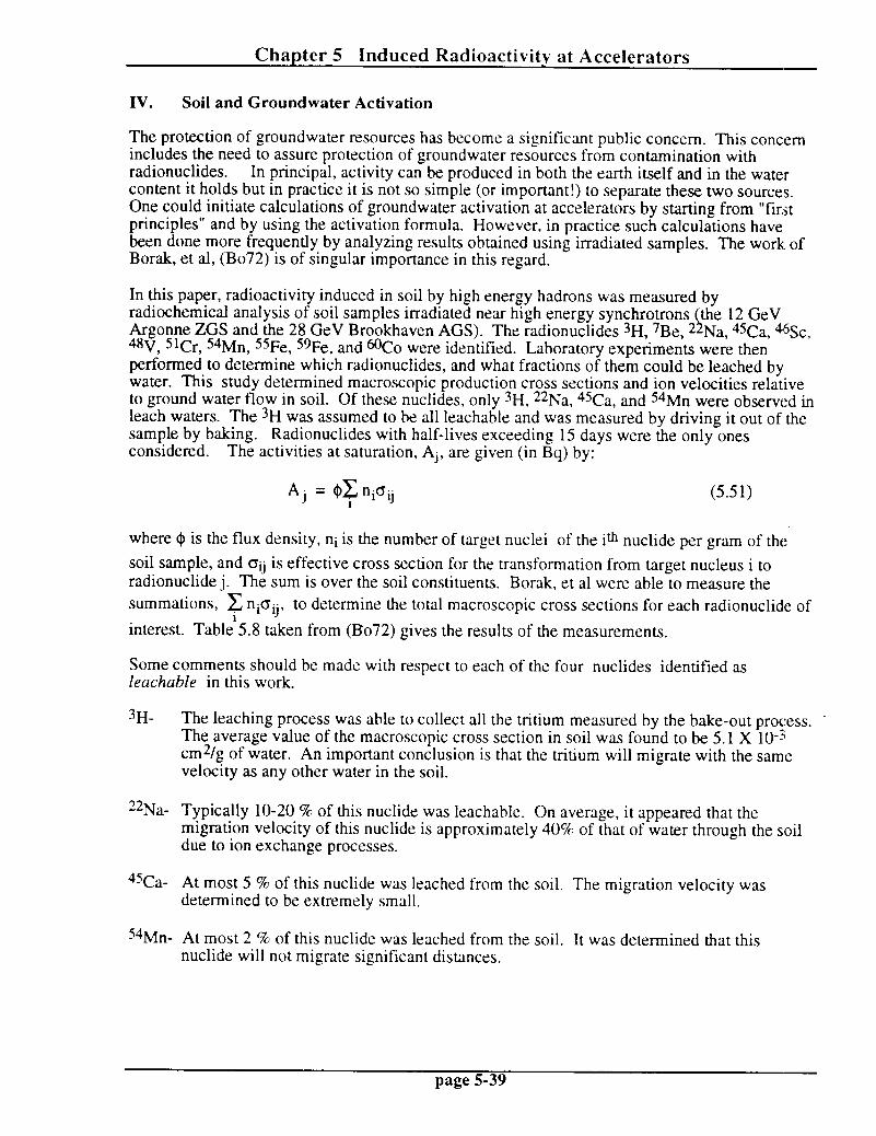
The protection of groundwater resources has become a significant public concern. This concern includes the need to assure protection of groundwater resources from contamination with radionuclides. In principal, activity can be produced in both the earth itself and in the water content it holds but in practice it is not so simple (or important!) to separate these two sources. One could initiate calculations of groundwater activation at accelerators by starting from “first principles” and by using the activation formula. However, in practice such calculations have been done more frequently by analyzing results obtained using irradiated samples. The work. of Borak, et al, (Bo72) is of singular importance in this regard.
In this paper, radioactivity induced in soil by high energy hadrons was measured by radiochemical analysis of soil samples irradiated near high energy synchrotrons the 12 GeV
1 Argonne ZGS and the 28 GeV Brookhaven AGS). The radionuclides 3H, 7Be, 2 48V, SlCr, 54Mn,
Na, ‘%a, ‘%c, 55Fe, 59Fe, and OCo were identified. Laboratory experiments were then
performed to determine which radionuclides, and what fractions of them could be leached by water. This study determined macroscopic production cross sections and ion velocities relative to ground water flow in soil. Of these nuclides, only “H, 22Na, 45Ca, and 54Mn were observed in leach waters. The 3H was assumed to be all leachable and was measured by driving it out of the sample by baking. considered.
Radionuclides with half-lives exceeding 15 days were the only ones The activities at saturation, Aj, are given (in Bq) by:
Aj = QF nidij (5.51)
where Q is the flux density, ni is the number of target nuclei of the i* nuclide per gram of the
soil sample, and Oij is effective cross section for the transformation from target nucleus i to radionuclide j. The sum is over the soil constituents. Borak, et al were able to measure the
summations, c nioij, to determine the total macroscopic cross sections for each radionuclide of
interest. Table’5.8 taken from (Bo72) gives the results of the measurements.
Some comments should be made with respect to each of the four nuclides identified as leachable in this work.
3H- The leaching process was able to collect all the tritium measured by the bake-out process. The average value of the macroscopic cross section in soil was found to be 5.1 X 10-j cm2/g of water. An important conclusion is that the tritium will migrate with the same velocity as any other water in the soil.
22Na- Typically lo-20 % of this nuclide was leachable. On average, it appeared that the migration velocity of this nuclide is approximately 40% of that of water through the soil due to ion exchange processes.
45Ca- At most 5 % of this nuclide was leached from the soil. The migration velocity was determined to be extremely small.
54Mn- At most 2 ‘9% of this nuclide was leached from the soil. It was determined that this nuclide will not migrate significant distances.
page 5-39

ChaDter 5 Induced Radioactivitv at Accelerators
TTT 000 “ttTtttt7 b 00000000 ----m-------
xxxxxxxxxxxx c‘r -. uq -* -* a -* ‘4 m w e4 w NCO.-m - b N - A 1 yj 4
y’y7‘TT”“Ty7 obboboobbooo -------c---m
xxxxxxxxxxxx ~“~o*~qqej~q~e4 ~co+-meJmam~-~
I* bb bl Abbbb
“TTY’“““” 0000 II----------
xxxxxxxxxxxx ~w~qm~q~o”-o”- meJeJmmwrQ---c4c4.2j
“b‘bLr,& I “7’97 T 02 d
ooooobb m--m------H-
xxxxxxxxxxxx ‘I F e? ‘T! c9 c9 6! ‘9 9 1 9 ‘: wl-lnmN--mmwln-
77 0~0.00000(D y I I
ooboobbb b b&B ---------m-e
xxxxxxxxxxxx
T”;“i” 000
&T,‘b”b”bT,‘,“bL
-dd-I----4--
xxxxxxxxxxxx
qqY:qTYqqfqF h~w-mNm*mm@4-
~7pT”bgy? T 7 000 11-m--------
xxxxxxxxxxxx cn~wcq~‘q~qacnw b+hi-w~Najwd&~
page S-40

Chapter 5 Induced Radioactivity at Accelerators
One can thus calculate the quantities of radionuclides that might pose a risk to groundwater in the environs of an accelerator. This can be done, as demonstrated by Gollon (Go78), by performing, for example, Monte-Carlo calculations in which the total stars (or nonelastic interactions above some threshold) produced in some volume of earth shielding are determined. The total number of atoms, Ki, of the i* nuclide that can be produced per star in that same volume would then be given by
Ki = 8
ne (5.52)
where Q is the macroscopic cross section (cm*/gram) for the i* radionuclide and &e is the total macroscopic nonelastic cross section (cm*/gram) for soil. lo-* cm*/gm for soil.
Gollon quotes a value of I& = 1.1 X Thus, a calculation of total stars in some soil volume per unit time can
be taken directly from the Monte-Carlo calculations. Gollon used the following values for 3H and **Na as selected from Borak’s paper for soils peculiar to Fermilab (glacial till):
K3 = 8.2 x lo4 1.1 x 10-2
= 0.075
K 22 = 2.1 x lOA = 0.02
1.1 x 10⁻² . (5.53.b)
One can then calculate the total number of atoms of radionuclides produced during some time interval in some volume by simply multiplying these factors by the number of stars (or nonelastic interactions) in the same volume. The number of atoms then can be converted to activity using the decay constant.
The quantity of ultimate concern, of course, is the resultant concentration in some drinking water supply. The United States Environmental Protection Agency (CFR76) limits such concentranons to those that would produce a dose equivalent of 4 mrem/year and specifically gives a limit of 20 pCi/ml for tritium as a legal limit. (An explicit limit for **Na is not specified by EPA.) The U.S. Department of Energy (DOE90) specifies limits using a more up-to-date methodology which results in a limit of 80 pCi/ml for 3H and 0.4 pCi/ml for **Na. At any rate, the concentration in the water must satisfy the following inequality:
ci c- ic 51.
maxi
The numerator in the summation is the concentration of some particular nuclide i while the denominator is the allowed limit. One needs to ultimately determine the concentration of the various radionuclides in the groundwater. The methods for calculating these concentrations will vary with the regulatory authority and the “conservatism” of the institution. The most conservative assumption is to assume that saturation values of production are reached (tantamount to assuming m movement of the radionuclides) and that the dilution in water is solely by the water contained in the soil in the immediate vicinity of the accelerator. This is almost absurdly conservative given the fact that there are no known methods for increasing the specific activity once the water departs the vicinity of the accelerator. This means that massive shielding is needed inside accelerator enclosures to reduce the neutron flux densities outside of the enclosures to very small values. Though certain types of soils (particularly clays) allow only very modest water movement (= a few centimeters or meters per year, dependent upon the details
page 5-41

ChaDter 5 Induced Radioactivitv at Accelerators
of the soil type), the “nonmovement” requirement is especially serious for 3H in that it implies the accumulation of the saturation value of the specific activity must be sufficiently diluted to meet the above criteria.
At Fermilab, a standard model allowing some movement and further dilution of water has been employed for many years (Go78). In this model, the vertical migration of water of about 2.2 meters per year is taken for water. The tritium vertical velocities are taken to be this value while the results obtained in (Bo72) are used to obtain a reduced value of about 1 m/year for **Na (the leachable fraction of the **Na according to (Bo72) is the only portion of that particular radionuclide included). The procedure that has been used at Fermilab is to allow decay during the downward migration of the radionuclides produced in one year to the highest aquifer (all Fermilab targets and beam dumps are above this level). At that point, it is assumed that the radionuclides are rapidly transported to a shallow well where it is assumed that the flow of water collecting the radionuclides is entirely used by a single, miserly user who consumes a very low value of 150 liters per day. Thus the annual production, as transported vertically, is diluted into the 5.5 X 107 cm?year that this represents. This simple model is generally conservative but does, in fact, neglect that fact that the water movement may m be uniform from year-to-year.
It is clear that better methods may be needed and a new model has been developed for use at Fermilab (Ma93). There currently is much research and development effort in this general area of hydrogeology given the need to carefully design sanitary landfills and other waste disposal sites to protect groundwater supplies from other contaminants as well as radioactivity. The new Fermilab model calculates the production of the radionuclides of concern in the same manner. However, instead of using the total production, the average concentration at saturation (i.e., with infinite irradiation time) in water near the vicinity of the beam absorber or target is calculated; The concentration after migration is, then, calculated by using up-to-date modeling techniques to calculate the reduction in the concentration due to dilution, diffusion, and radioactive decay. At the point of concern, usually the location of an aquifer suitable for consumption, the concentrations calculated are then substituted into Eq. (5.54) in order to determine if a shielding design is adequate. The new Fermilab model has some strong advantages over its predecessor. It calculates concentrations directly and also calculates them at saturation, rather than on the basis of annual production. In view of the fact that radionuclides migrate rather slowly in glacial till, the latter may be far more realistic.
A report by the Superconducting Super Collider Central Design Group (Ja87) attempts to estimate the dilution for a shallow uncased well in an aquifer a distance r from a beam loss point also in the aquifer. The loss point is assumed to be within the drawdown zone of the well. This model utilizes an elegant method developed by J. D. Jackson for a simple geology that involves a single uniform strata of earth above some level of impervious stratum. Fig. 5.14 taken from (Ja87) shows the situation described by this model. In this model, a given well is modeled by the profile of depth of water h(r) at distance r from the well. h(r) is determined by the depth of a test well at radius r from the well under consideration. The well is assumed to supply a volume Q of water per day. Conservation of water is the hallmark of this model. The flux of water is determined by the gradient relation,
s, &y (5.55)
where Sr is the inward flux at radius r and k is a constant with dimensions of volume per unil time per unit area and is characteristic of the soil.
page 5-42

Chapter 5 Induced Radioactivity at Accelerators
Conservation of water yields the steady-state equation:
Q = 2x:r h(r) S, = 2x kr h$ = rck-$$ . (5.56)
The quantity 2~ r h$ corresponds to the rate of change of volume of the cylindrical shell Iof
height h (“the head”) with respect to r.
This equation has the solution:
Q ln(r/r,) = x k[h2(r) - ht] (5.57)
where r, is the radius of the well and ho is the height of water above the impervious stratum at the well. If H is the depth of the impervious layer below the water table, the radius of influence R of the well can be defined by the relation:
In (R/r,) = x k[H’- ha
Q .
Ground surface
(5.58)
Water table
Fig. 5.14 Hydrological model of a shallow well in proximity to an accelerator tunnel where a beam loss occurs. The radioactive region is represented in cross section by the shaded rectangle on the right H, representes the elevation of the water table above the impervious stratum. [Reproduced from (Ja87j.l
page 5-43

Chapter 5 Induced Radioactivity at Accelerators
However, the detailed solution is not necessary.
Now, suppose that there is a well a distance r away from the region of deposition of radioactivity near an accelerator. We also assume that the activation zone lies below the water table and that the deposition region lies within the radius of inlluence of the well. This assumption leads to higher concentrations than would be obtained if the activation zone were totally, or partially, above the water table.
The amount of activity drawn into the well is determined by the rate of pumping Q and the necessary total flow through a cylinder of radius r and height h(r) as we have seen. Let AV be the volume of soil yielding Q gallons of water.
The cylindrical shell providing this amount of water will be of radial thickness Ar, where AV = 2xrh(r)Ar. The fraction F of the volume of activity included in this shell can be said to be given by:
F = F = THrr\y =et
(5.59)
provided that Ar < t.
If the activated region contains activity, A (either total activity or that of a particular radionuclide of interest), the corresponding specific activity, a, in water drawn from the well is thus given by:
a=FA=F A Q m = (2;:th)+(&)A = (2x:tD)iA
(5.60)
where f = D/h is the fraction of the total height of the cylindrical shell occupied by the activated region and p is the porosity of the soil. The pumping volume Q is implicit in f. Porosity values vary considerably but in general are in the range,
0.2 c p < 0.35. (5.61)
Thus, this formula may be used to obtained an estimate of the specific activity as a function of distance from the well, although it is perhaps not too useful for applications to beam losses far from the well. By definition, f 5 1 and the lower value of porosity can be used to obtain upper limit estimates of the concentration. It must be emphasized that this model depends upon uniformity of water conduction by the strata. The presence of “cracks”, of course, can provide much more rapid movement that is ~JJ well-described by this simple model.
page 5-44

Chapter 5 Induced Radioactivity at Accelerators -
References
(Ar69)
(Ar73)
(Ba69)
(Bo72)
(Bu89)
(Ce69)
(CFR76)
(CFR89)
(CFR93)
(Co78)
(DOE90)
(Go76)
(Go78)
(Ho69)
(Ja87)
(Ma93)
T. W. Armstrong and J. Barish, “Calculation of the residual photon dose rate due to the activation of concrete by neutrons from a 3-GeV photon beam in iron,” in Proceedings ‘of fhe Second International Conference on Accelerator Radiation Dosimetty and Experience, (Stanford, CA 1969).
T. W. Armstrong and R. G. Alsmiller, Jr, Nucl. Sci. Eng. 38 (1973) 53-62.
M. Bar-bier, induced Radioactivity, (North-Holand Publishing Company, Amsterdam and London, Wiley Interscience Division, John Wiley and Sons, Inc, New York, 1969).
T. B. Borak, M. Awschalom, W. Fairman, F. Iwami, and J. Sedlet, “The underground migration of radionuclides produced in soil near high energy proton accelerators”, Health Physics 23 (1972) 679-687.
S. W. Butala, S. I. Baker, and P. M. Yurista, ’ Measurements of radioactive gaseous releases to air from target halls at a high-energy proton accelerator”, Health Physics 57 (1989) 909-916.
H. Cember, Introduction to Health Physics, (Pergamon Press, New York, 1969).
United States Code of Federal Regulations, Title 40, Part 141.16, “National primary drinking water standard for beta- and gamma- emitting radionuclides”,l976.
United States Code of Federal Regulations, Title 40, Part 61, Subpart H, “National Emissions Standard for Hazardous Air Pollutants (NESHAP) for the emission of radionuclides other than radon from Department of Energy Facilities”,l989.
United States Code of Federal Regulations, Title 10 Part 835, “Occupational Radiation Protection at Department of Energy Facilities”, 1993.
B. L. Cohen, “Nuclear cross sections”, Handbook of Radiation Measurement and Protection, Section AT Volume I Physical Science and Engineering Data”, A. Brodsky, editor (CRC Press, Inc., West Palm Beach, Florida, 1978).
U. S. Department of Energy Order 5400.5, “Radiation Protection of the Public and the Environment” (1990).
P. J. Gollon, “Production of radioactivity by particle accelerators”, Fermilab Report TM- 609 and also IEEE Trans. Nucl. Sci. NS23 No. 4 (1976) 1395.
P. J. Gollon, “Soil activation calculations for the anti-proton target area”, Fermilab Report TM-81 6 (1978)
M. Hofert, “Radiation hazard of induced activity in air as produced by high energy accelerators”, in Proceedings of the Second lnternafional Conference on Accelerator Radiation Dosimetry and Experience, (Stanford, CA 1969).
J. D. Jackson, editor, G. D. Murdock, D. E. Groom, J. R. Sanford, G. R. Stevenson, W. S. Freeman, K. O’Brien, R. H. Thomas, “SSC Environmental Radiation Shielding”, SSC Central Design Group Report SSC-SR-1026 (1987).
A. J. Malensek, A. A. Wehmann, A. J. Elwyn, K. J. Moss, and P. M. Kesich, “Groundwater Migration of Radionuclides at Fermilab”, Fermilab Report TM-l 851 (August, 1993).
page 5-45 -

Chapter 5 Induced Radioactivity at Accelerators -
(NC96)
(Pa58)
(Pa73)
(Sl68)
(Su65)
(Sw90)
(Th88)
(Tu84)
(Va93)
(Va94)
R. H. Thomas (chair), W. R. Casey, N. Rohrig, J. D. Cossairt, L. A. Slaback, K. O’Brien, G. B. Stapleton, and W. P. Swanson, National Council on Radiation Protection and Measurements (NCRP), NCRP Report 51 (Revised)--in preparation.
H. W. Patterson and R. Wallace, ” A method of calibrating slow neutron detectors, Lawrence Radiation Laboratory Report UCRL-8359 (1958).
H. W. Patterson and R. H. Thomas, Accelerator He&h Physics, Academic Press, New York, 1973.
D. A. Slade, Editor, Meteorology and Atomic Energy (U. S. Atomic Energy Commission, Off ice of Information Services, July, 1968).
A. H. Sullivan and T. R. Over-ton, “Time variation of the dose-rate from radioactivity induced in high-energy particle accelerators”, Health Physics 11 (1965) 1101-l 105.
W. P. Swanson and R. H. Thomas, “Dosimetry for radiological protection at high energy Particle Accelerators”, Chapter 1 in The Dosimetry of ionizing Radiation, Volume III (Academic Press, 1990).
R. H. Thomas and G. R. Stevenson, “Radiological safety aspects of the operation of proton accelerators”, Technical Report No. 283, IAEA, Vienna, 1988.
J. W. N. Tuyn, R. Deltenre, C. Lamberet, and G. Roubaud, “Some radiation aspects of heavy ion acceleration”, Proc. 6th Int. Cong. IRPA, Berlin (1984) 673.
K. Vaziri, V. Cupps, D. Boehnlein, D. Cossairt, A. Elwyn, and T. Leveling, “APO stack monitor calibration”, Fermilab Radiation Physics Note 106, May 1993.
K. Vaziri, V. R. Cupps, D. Boehnlein, D. Cossairt, and A. Elwyn, “A detailed calibration of a stack Monitor used in the measurement of airborne radionuclides at a high energy proton accelerator”, Fermilab Report FERMILAB-Pub-96/037, 1996, submitted to Health Phjys.
page 5-46

Chapter 5 Induced Radioactivity at Accelerators-Problems -
1. A copper beam stop has been bombarded with high energy hadrons for 30 days and
exhibits a dose rate of 100 mrem/hr at 1 meter away 1 day after the beam is turned off.
Maintenance work needs to be scheduled in the vicinity within the next 6 months. Using
both Gollon’s Rule # 3 (as derived by Sullivan and Over-ton) and the Bar-bier Danger
parameter curves, predict the cooling curve and determine when the dose rate is less than
a 20 mrem/hr maintenance work criteria. Make a table of dose rate versus cooling time in
days for both methods. How well do the two methods agree? (Hint: Use initial value of
the dose rate to scale “0” values.)
2. A 100 GeV beam ( 1012 protons/second) strikes the center of a large solid iron cylinder 30
cm in radius for 30 days. Use the FLUKA star density curves from the Chapter 3 (Fig
3.15) and the “o” factors calculated by Gollon to estimate the residual dose rate after 1
day cooldown at contact with the side of the cylinder in the “hottest” spot. Using
Gollon’s third rule, how long must the repair crew wait to service this time in a contact
radiation field of absorbed dose rate < 10 rad/hr?
3. A copper target is bombarded with high energy protons such that 10 stars per incident
proton are produced. If the incident beam is 10’ 1 p/s, what is the specific activity
(average) of 54Mn that is produced after two years of operation? 54Mn has a high energy
spallation production cross section of about 20 mb in Cu. The target is a cylinder, 10 cm
radius by 15 cm long. The half-life of 54Mn is 3 12 days. Express the answer in both
Bq/cm3 and Wcm 3. (Hint: This problem is best if the calculation is done at saturation
and then corrected for the noninfinite irradiation time. Also, one needs to use the
inelastic cross section given, for example, in Chapter 3.)
4. A 20 m long air gap has a beam of 1Ol2 p/s of high energy protons passing through it.
First, calculate the production rate of * 1C in the gap at equilibrium if one approximates air
in the gap by nitrogen and assumes (3 (l lC> = 10 mb. Assume that there are no significant
losses of beam by interaction after checking to see that this assumption is, in fact, true.
Table 1.2 should contain helpful information.
page 5-47 -

Chapter 5 Induced Radioactivity at Accelerators-Problems -
a) If the air gap is in a 10 X 10 X 20 meter3 enclosure with no ventilation, calculate the
equilibrium concentration of 11C in the room (in units of pCi/m3) assuming extremely
rapid mixing (i.e., no time allowed for decay while mixing occurs) of the enclosed air.
Compare the concentration with the derived air concentration values in Table 5.5 and
calculate, using simple scaling, the dose equivalent to a worker who spends full time in
this room. (This is a purely hypothetical scenario due to the much larger hazards due to
such an intense direct beam!)
b) Calculate the concentration if two (2) air changes/hr are provided.
c) Assume the exhaust of the ventilation described in part “b” is through a 10 cm radius
stack 25 m tall. Calculate the air speed in the stock, and the the emission rate G/s. Then
using Cember’s version of Sutton’s equation for tall stacks to estimate the concentration
directly downwind at ground level, and hence the dose equivalent 1 km away with
moderately stable meteorological conditions and an average wind spreed of 10 km/l-n-.
d) Perform the same calculation requested in “cl’ using the more general version of Sutton’s
equation appropriate to short stacks and assume the stack height to be 3 meters. All oth’er
conditions of the problems are the same as in “c”.
5. In soil conditions similar to those at Fermilab, a volume of soil around a beam dump
approximately 10 m wide X 10 m high 20 m long is the scene of a star production rate
(averaged over the year) of 0.02 star/proton at a beam intensity of 1012 protons/set.
a) Calculate the annual production of 3H (tI/2 = 12.3 years), the saturated activity (in Bq (9
Ci), and the average saturated specific activity in the above volume’s water (assume 10%
water content by volume).
b) Use the older “Fermilab Model” to calculate the concentration at the nearest well.
Assume the activation region (beam loss point) is 50 m above the aquifer and the usual
migration velocities.
c) “Conservatively” apply the “Jackson Model” to estimate the concentration at a well 100
meters distant from the center of the activation region.
page 5-48

ChaDter 6 Tonics in Radiation Protection Instrumentation at Accelerators
I. Introduction
The purpose of this discussion is to summarize instruments and dosimeters currently used in the environment of particle accelerators to measure and characterize the radiation fields. In particular, the emphasis here is on instrumentation that addresses those aspects of accelerator radiation fields that pose special problems. Thomas and Stevenson (Th88) and Swanson and Thomas (Sw90) also discuss these matters. Cember (Ce69) is a comprehensive health physics textbook that covers the basics of radiation measurement instrumentation quite well. The book by Knoll (Kn79) is a well-written and reasonably up-to-date treatise on this subject. It should be noted here that virtually all particle detection techniques that have been devised by physicists have, to some degree, been employed in radiation measurements at accelerators. For example, the particle yields discussed previously are to a large degree a “product” of the basic scientific research program for which the accelerators have been built. The “burden” is on the radiation protection practitioner to be able to astutely determine which data, among the flood of results which pours out of the physics experiments, has immediate practical application to radiation protection!
Cember (Ce69) has given a good summarv of counting statistics which bears repeating here. Radioactive decays are randomly occurring events having a sampling distribution which is corrrectly described by the binomial distribution given by the expansion of the binomial:
n(n-1) (p + q)” = pn + npn-lq + Tpri-2q2 + n(n--Nn-2) n-3 3 3, p q +... (6.1)
where p is the mean probability for occurence of an event, q is the mean probability of non- occurrence of the event and thus p + q = 1, and n is the number of chances of occurrence. The probability of exactly n events occurring is given by the first term, the probability of n - 1 events is given by the second term, etc. For example, in the throwing of a die, the probability of throwing a “one” is l/6 and the probability of throwing a “one” 3 times in a row (n = 3) is:
P = (1/6)3 = l/216. (6.2)
In three throws, the probabilities of throwing 2 “ones”, 2nd, 3rd, and 4* terms of the expansion.
1 “one” and no “ones” are given by the
This distribution becomes equivalent to the normal distribution (or Gaussian distribution) given by the following, when n has an approximate value of at least 30:
p(n) = &exd<n - n)52o’], (6.3)
where p(n) is the probability of finding exactly n, fi is the mean value, and CY is the standard deviation.
For rare (highly improbable) events (typically radioactive decays or particle interactions fall into this category), the binomial distribution approaches the Poisson distribution. In this distribution, the probability of obtaining n events if the mean value is R, is given by:
-n -i
p(n) = n e 0 n! ’ (6.4)
page 6-1

Chapter 6 Topics in Radiation Protection Instrumentation at Accelerators
For example consider the decay of 0.001 l.rCi of activity. For this, ii = 37 decays/set. The probability of exactly observing this number of events in any one second is:
where one can apply Sterling’s approximation
n! = 2Tcn l’ E ( )-ii
n
(6.5)
(6.6)
to evaluate the factorial (and get considerable cancellation). Thus ~(37) = 0.066. As in the case of the normal distribution, 68 % of the events would lie within one standard deviation of the mean, 96 5% of the events would lie within 2 standard deviations of the mean. For the Poisson distribution.
CJ = Ai. (6.7)
The relative error, o/n, is thus 9.
Often, when dealing with instrumentation, counting w are involved. For these the following holds;
r-to =fi*a r t t (6.8)
where r is the counting rate per unit time, cur is its standard deviation, and t is the counting time during which the rate is measured. (The quantity t, for example, could even be the integration time constant of some instrument.)
It follows that
(-J=fi= r t
dn+. (6.9)
Usually, backgrounds are present and must be dealt with. The standard deviation of the m counting rate is given as
on= Jm-d-7 (6.10)
where the subscripts g refer to the measurement of the gross countinp rate while the subscripts bg refer to the measurement of the backrzround counting rate.
In general, the common statistical tests are valid for Poisson statistics.
page 6-2

Chapter 6 Topics in Radiation Protection Instrumentation at Accelerators
Another quantity that sometimes becomes important is the resolving time of an instrument. This is the time that the detector, following an event, is incapable of measuring a second event. It can be measured by exposure to two different sources of radiation [(the “two-source method” of (Ce69)]. A certain detector has a measured background rate of Rb and responds to first source alone with a rate Rt and to the second source alone with a rate R2 ?I both Rt and R2 include thle background). When exposed to the two sources simultaneously, the measured rate is R12. The resolving time, 7, is given by
T= Rt +RZ-Rt2-Rhg
R&-R;-R; . (6.11)
In many situations, it is often easier to determine T from the physical properties of the detection mechanism or from the electronic time constants related to the resolving time in the measurement circuitry. When the observed counting rate of a sample is Rc,, then the “true” counting rate, R, that would have been observed with a “perfect” instrument having a resolving time of zero is given by
K.-l R = l-R&
(Kn79) has a very detailed discussion of count rate considerations and the optimization of the counting statistics. He also presents a discussion of paralyzable versus non-paralyzable dead time corrections.

Chapter 6 Topics in Radiation Protection Instrumentation at Accelerators
II. Special Considerations for Accelerator Environments
There are a number of features of accelerator radiation fields which merit attention in choosing instrumentation or measurement techniques. The most important of these are briefly summarized here.
Laree RanPe of Flux Densities. Dose Equivalent Rates. etc,
The magnitudes of the quantities to be measured encountered at accelerators may range from fractional mrem/year (environmental monitoring and studies) to the very large (up to megarad) values of absorbed dose of concern in radiation damage situations. [It is customary to quantify radiation fields in terms of absorbed dose at levels above those encountered in personnel protection (= 1 rem).]
Possible Large Instantaneous Values of Flux Densities of Flux Densities. Dose Equivalent Rates, f&L
Certain accelerators (e.g., linacs, rapid cycle synchrotrons, and “single-turn” extracted beams from synchrotrons) can have very low average flux densities, etc. but have extremely high instantaneous rates. Such circumstances arise at accelerators at high intensities or in situations where the “duty factor” (the fraction of the time the beam is actually present because of accelerator characterisics) of a high intensity radiation field is small. Thus, the dead time considerations described above must be taken into account in special ways or the measured results can be found to be misleadingly low. Some instruments can be completely paralyzed by high instantanous rates. In those cases, the effect of deadtime on the instantaneous counting rate that is present is the relevant parameter.
Large Dvnamic Ranre of Neutron Radiation Fields
At any given accelerator capable of producing neutrons, the properties of nuclear interactions make it highly probable that neutions will be present at all energies from thermal (<E+ = 0.025 eV) up to the energy of the beam. As we will see below and in the references cited, the methods of detection of neutrons vary considerably over this energy domain. Thus the choice of instrumentation is crucial to the success of the measurement. For no other particle-type is the energy range so large and so diverse with respect to applicable detection techniques as it is for neutrons.
Presence of Mixed Radiation Fields
At accelerators, one has to consider that any given radiation field external to shielding is likely to be comprised of a mixture of photons, neutrons, and (at high energies and forward angles) muons. (Inside of shielding, these particles will often be accompanied by a multitude of others.) Also, virtually all neutron fields contain at least some photon component due, at least, to the capture of thermal neutrons in (n, y) processes. Also, muon fields, at least those near ion accelerators, contain some neutron component. Thus the choice of instrumentation is somewhat dependent upon what particles are present in addition to the one beinE measured. In certain situations, the radiation field component that is not of interest can actually mask the one of concern.
page 6-4

Chapter 6 Topics in Radiation Protection Instrumentation at Accelerators
Directional Sensitivity
Certain instruments intrinsically exhibit directional sensitivity. This feature can be either beneficial or harmful, depending upon the situation. In all instances, it must be understood. It can lead to underestimates in radiation fields where all particles are not monodirectional. Directional sensitivity can actually be useful in certain circumstances to “find” sources of unwanted radiation.
Sensitivitv to Features of the Accelerator Environment Other than Ionizing Radiation
While the focus of this discussion is on ionizing radiation, other features must be taken into account. The most prominent of these is the presence of radiofrequency radiation (RF) at some locations that can perturb instruments acting as “antennas”. Environmental features such as temperature and humidity can also be important.
page 6-5

Chapter 6 Topics in Radiation Protection Instrumentation at Accelerators -
III. Standard Instruments and Dosimeters
This section will review instruments and dosimeters that are generally available from commercial sources.
Ionization Chambers
A basic type of instrument used at accelerators to measure absorbed dose rates is the ion chamber. Such devices are used at high energy accelerators extensively. They rely on the collection of charge liberated by particles passing through a gas. Some advanced concept detectors now employ liquids for the ionization medium. A fortunate result of atomic physics is that the energy dissipation per ion pair, W, is nearly a constant over a number of gases as exhibited by Table 6.1 taken from (Kn79).
Table 6.1 Values of the energy deposition per ion pair (the W-value) for different gasesa. [Reproduced from (Kn79).]
w value in eV/Ion Pair
Gas Fast Electrons APb
A 27.0 25.9 He 32.5 31.7 H2 38.0 37.0 N2 35.8 36.0 Air 35.0 35.2 02 32.2 32.2
CH, 30.2 29.0
“Data from S. C. Curran, “Proportional Counter Spectromeq,” in Beta and Gamma-Ray Spcrros- copy, K. Siegbahn (d). Elswier-North Holland, Amsterdam (1955).
Thus, if a given charged particle liberates a certain amount of energy, E, in the chamber, an electrical charge, Q, will be released according to:
Q (Coulombs) =
1.6 X 10⁻¹³& (MeV) w (eV,ion pair) . (6.13)
Q can be collected by electrodes held at some voltage V. The collected charge generates a small change in V, AV (volts), in accord with the relation,
AV = AQ/C (6.14)
where C is the capacitance of the total circuit (including that of the chamber) in units of Farads. From (Kn79), for typical chambers, C is of the order of lo-lo Farads. Knoll (Kn79) gives many details of the processes that determine the size and form of the electrical signals that can be generated in a measurement. Such chambers can be operated either in a “DC” or “ratemeter” mode, or in a mode in which the charge is integrated over some time period with the total charge collected, then “digitized” into pulses that represent some increment of “dose”. In the “ion chamber” mode of operation, the applied voltage is sufficiently small so that gas multiplication (charge amplification) does not occur.
page 6-6 -

Chapter 6 Topics in Radiation Protection Instrumentation at Accelerators
In the most simple-minded approach, one might believe that for measurements in photon fields one could fill such a chamber with gases that “mimic” tissue (so called “tissue equivalent” gases, or even hydrocarbons, for most purposes) and, with suitable calibration, convert the charge collected into absorbed dose. However, since ion chamber gases are in general much less dense than tissue, one must also “capture” the energy of the secondary electrons which, in the region of a few MeV, have ranges of several meters. It is thus necessary to use “compensation” techniques in which the solid material of the walls is chosen because of properties that “match” those of the gas. This condition can be readily achieved by use of any material with atomic number close to that of the contained gas, to sufficient accuracy for most practical purposes. Thus, aluminum and especially plastics, for example, are reasonably “equivalent” to tissue and air. Such walls must be of thickness to establish “electronic equilibrium”. In this condition, the flux of secondary electrons leaving the inner surface of the wall is independent of the thickness. Table 6.2 taken from (Kn79) gives the wall thicknesses needed to establish electronic equilibrium for photons.
Table 6.2 Thicknesses of ionization chamber walls required for establishment of electronic equilibrium? [Reproduced from (Kn79).]
Photon Energy (MeV) -l7licknessb (g cm-q
0.02 0.0008 0.05 0.0042 0.1 0.014 0.2 0.044 0.5 0.17 1 0.43 2 0.96 5 2.5
10 4.9
OFrom International Commission on Radiation Units and Measurements Rc- port ICRU X20 (1971). *The thickncs.ses quoted are based on the range of electrons in water. The vahes will lx substantiaIly umcct for tissue-equivalent ionization chamber waih and al.w for air. Half of the above thickncsa will give an ionization current within a few percent of its equilibrium value.
Finally, the measurement of absorbed dose is accomplished by application of the Bragg-Gray principle, which states that the absorbed dose Dni in a given material can be deduced (with suitable unit conversions) from the ionization produced in a small gas-filled cavity within that material as follows:
D, = WS,P, (6.15)
where W is the average energy loss per ion pair, S, is the ratio of mass stopping power (energy loss per unit density, e.g., MeV/g cms2) of the material of interest relative to the chamber gas, and P is the the number of ion pairs formed. For Drn to be in grays (J/kg), W must be expressed in Joules per ion pair and P in ion pairs per kg.
page 6-7
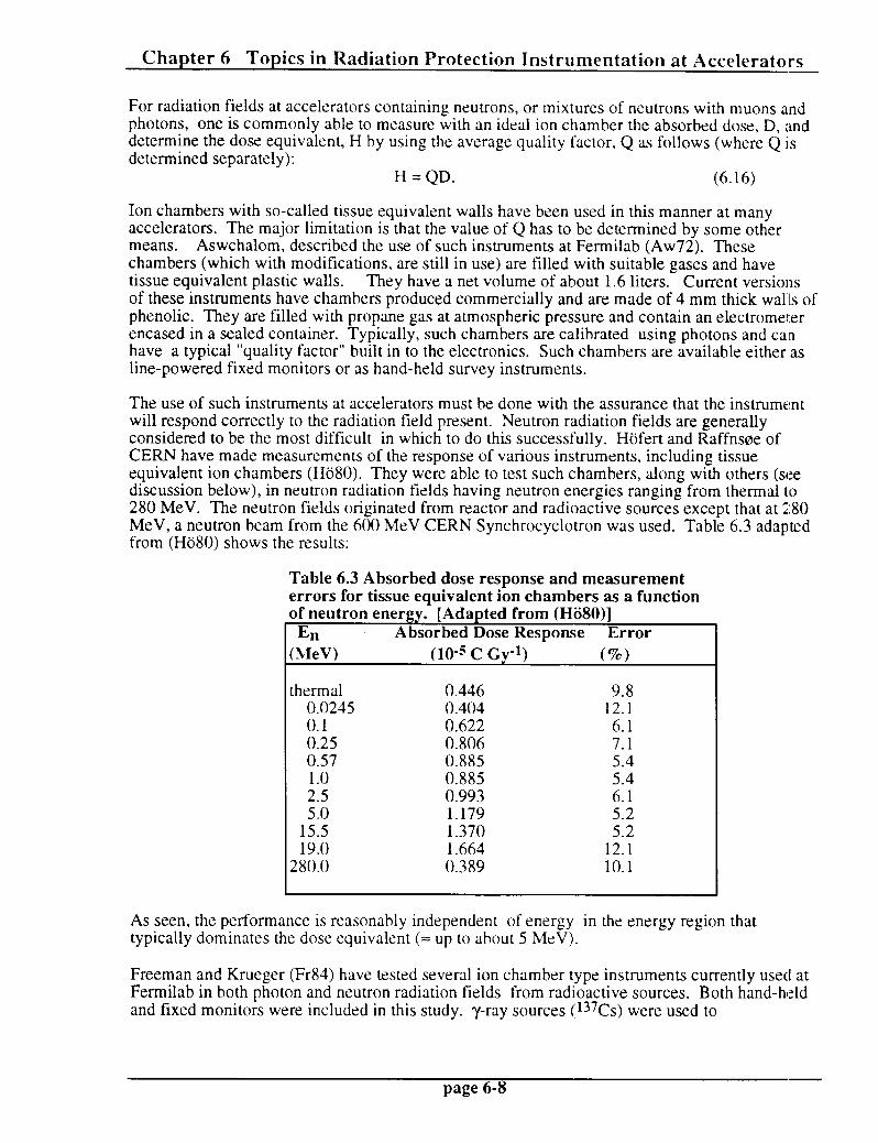
Chapter 6 Topics in Radiation Protection Instrumentation at Accelerators
For radiation fields at accelerators containing neutrons, or mixtures of neutrons with muons and photons, one is commonly able to measure with an ideal ion chamber the absorbed dose, D, and determine the dose equivalent, H by using the average quality factor, Q as follows (where Q is determined separately):
H=QD. (6.16)
Ion chambers with so-called tissue equivalent walls have been used in this manner at many accelerators. The major limitation is that the value of Q has to be determined by some other means. Aswchalom, described the use of such instruments at Fermilab (Aw72). These chambers (which with modifications, are still in use) are filled with suitable gases and have tissue equivalent plastic walls. They have a net volume of about 1.6 liters. Current versions of these instruments have chambers produced commercially and are made of 4 mm thick walls of phenolic. They are filled with propane gas at atmospheric pressure and contain an electrometer encased in a sealed container. Typically, such chambers are calibrated using photons and can have a typical “quality factor” built in to the electronics. Such chambers are available either as line-powered fixed monitors or as hand-held survey instruments.
The use of such instruments at accelerators must be done with the assurance that the instrument will respond correctly to the radiation lield present. Neutron radiation fields are generally considered to be the most difficult in which to do this successfully. Hiifert and Raffnsoe of CERN have made measurements of the response of various instruments, including tissue equivalent ion chambers (Hii80). They were able to test such chambers, along with others (see discussion below), in neutron radiation fields having neutron energies ranging from thermal to 280 MeV. The neutron fields originated from reactor and radioactive sources except that at 280 MeV, a neutron beam from the 600 MeV CERN Synchrocyclotron was used. Table 6.3 adapted from (Hii80) shows the results:
Table 6.3 Absorbed dose response and measurement errors for tissue equivalent ion chambers as a function of neutron energy.- [Adapted from (HSO)]
En Absorbed Dose Response Error
(MeV) (l@ C Gv-I) (%)
thermal 0.446 9.8 0.0245 0.404 12.1 0.1 0.622 6.1 0.25 0.806 7.1 0.57 0.885 5.4 1.0 0.885 5.4 2.5 0.993 6.1 5.0 1.179 5.2
15.5 1.370 5.2 19.0 1.664 12.1
280.0 0.389 10.1
As seen, the performance is reasonably independent of energy in the energy region that typically dominates the dose equivalent (= up to about 5 MeV).
Freeman and Krueger (Fr84) have tested several ion chamber type instruments currently used at Fermilab in both photon and neutron radiation fields from radioactive sources. Both hand-held and fixed monitors were included in this study. ‘y-ray sources (l37Cs) were used to
page 6-8

Chapter 6 Topics in Radiation Protection Instrumentation at Accelerators -
provide the photons while a 23*PuBe neutron source was used for the neutron measurements. [The PuBe source has neutrons spanning the region from E, < 0.25 MeV to E, = 11 MeV with an average energy of about 4.1 MeV.] Several different detectors were tested and are briefly described in Table 6.4 taken from (Fr84). The results of the measurement are given in Tables 6.5 and 6.6 taken from (Fr84). The measurements were made both indoors and outdoors to be able to understand the effects of room scattering
Simple tests that have been conducted at Fermilab indicate that absorbed dose measured in muon fields is adequately understood using the y-ray calibration of the instruments. These tests have involved comparison with direct measurements of the muon fluence using counter-telescope techniques, and typically are in agreement within about 10 per cent for the Fermilab-built instruments described previously. This is to be expected since muons at high energies behave as”minimum ionizing particles” whose loss of energy in matter proceeds, to first order, exactly as does that of electrons.
Practical problems encountered with such ion chambers are mostly those due to radiofrequency interference, pulsed radiation charged fields, and environmental factors such as temperature extremes and humidity. Cossairt and Elwyn (Co87) determined that air-filled pocket ion chambers of the type that are commonly issued to personnel to allow real-time monitoring of exposure to y-rays, performed very well in muon radiation fields (measuring absorbed doses to within about f 15 %). This is probably due to the fact that the ratio of muon stopping power in tissue to that m air for energies between 1 and 800 GeV is 1.07 f. 0.05 (St83).
Table 6.4 Descriptions of ionization chamber used at Fermilab. The instruments designated “new” were produced after 1980 while those designated “old” were produced earlier. [Reproduced from (F&4).]
Old Chipmunk -
New Chipmunk -
Old Scarecrow -
New Scarecrow -
TEIR -
HP1 1010 - . .
A high-pressure gas-filled ionization chamber designed by Fermllab and built by LND, Inc. with 4 mm thick walls of
tissue-equivalent plastic. The fill gas is 150 ?SiG of ethane. The chamber is enclosed in a protective box vhlah aontaina a ’ sensitive electrometer and associated electronics to measure the current output and convert it to dose-equivalent rate. Switch-selectable Quality Factors of 1, 2.5 or 5 are available.
.
Similar to Old Chipmunk except for use of a phenolic-lined ionization chamber, filled with propane gas at atmospheric pressure and an electrometer encased in a sealed container.
A high-pressure ionization chamber with bare (stainless steel) walls filled with 150 PSIG of ethane gas. Sfmllar to electrometer for Old Chipmunk but with a’flxed Quallty Factor of 4 and capability to measure dose rates 100 times higher (up to 10 Rem/hr).
Same electronics as Old Scarecrow, but with phenolic-lined chamber and electrometer enclosure identical to the ones in the New Chipmunk.
Tissue Equivalent Integrating Ratemeter. A commercially avallabie Tissue Equivalent ion chamber’like that supplied with the REM, Inc. model 112, but interfaced to Fermilab-designed electronics. The ioh;chamber is filled with 18 PSIG ethane gas and has a nearly parallel plate geometry. .
Commercially available survey meter consisting of a gas-filled multiplying ion chamber and associated electronics. The chamber is filled with 100 mm Hg of TE gas inside a TE pIe8tic chamber.
page 6-9

Chapter 6 Topics in Radiation Protection Instrumentation at Accelerators
Table 6.5 y-ray test results for ionization chambers used at Fermilab. The instruments designated “new” were produced after 1980 while those designated “old” were produced earlier. [Reproduced from (Fr84).]
Instrument Instrument Serial Serial No. No. r
Old Old Chipmunk Chipmunk 90 90 .122 .533 .411 .411 .126 .126 .544 .418 1.02
New New Chipmunk Chipmunk
Old Old Scarecrow Scarecrow
173 173 .148 .54Q .401 .167 .566 .399 1.00 .9i!8 .9i!8
28 25.47 25.88 .41 25.38 25.81 .43 1.05 .907 .907
NW NW Scarecrow Scarecrow
TEIR TEIR
HP1 1010
33 24.68 25.09 .41 24.71 25.11 .40 0.98 .907 .907
3 .035 .386 .351 .025 .394 .369 1.05 1.05
2 .0107 ,372 .361 -016 .402 ,386 1.07 1.03
Outdoor Outdoor
63 63 Bkg. Bkg. Gross Gross Net Net
Indoor Indoor
Bkg. Bkg. Gross Gross Net Net l-
Ratio Ratio Indoor Indoor Outdoor Outdoor
7
Table 6.6 Neutron test results for ionization chambers used at Fermilab. The instruments designated “new” were produced after 1980 while those designated “old” were produced earlier. [Reproduced from (Fr84).]
Outdoor Outdoor
Serial Serial No. No. Bkg. Bkg. - - Gross Gross Net*+ Net*+
Indoor Indoor mrad mrad k. k. ) ) hr hr t
Bkg. Bkg. Gross Net*' Net*' Instrument Instrument
Old Old Chipmunk Chipmunk
New New Chipmunk Chipmunk
Old Old Scarecrow Scarecrow
New New Scarecrow Scarecrow
TEIR TEIR
HP1 HP1 1010 1010
90 90
173
28
33
3
2
,122 ,122 .%7 .765 (.585)
,148 ,148 .868 ,668 (.488)
25.47 26.24 .70 (.52)
24.68 25.43 .68 (.50)
.035 .822 .834 (.654;
.0107 .501 .505 (.325)
,126 ,126 1.09 1.09
.167 .994 .994
25.38 26.33
24.71 25.56
.025 .915
.016 .498
.872 t.692)
.767 (.5871
.86 (,68)
.77 l.59)
.943 ( .763)
.496 (.316)
Calltration Calltration Correction Correction Factclr Factclr -- --
.905 .905
Ratio Ratio Indoor Indoor -- -- Outdoor Outdoor -- --
iNumbers iNumbers not not in in parentheses parentheses result result fran fran applying applying the the calibration calibration correction correction factors factors in in Table Table $,5 $,5 *Numbers *Numbers in in parentheses parentheses include include subtraction subtraction of of 0.18 0.18 mrad/hr mrad/hr y-contribution. y-contribution.
1.18
1.20
1.31
1.18
1.17
.97
page 6-10

Chapter 6 Topics in Radiation Protection Instrumentation at Accelerators
Geiger-Mueller Detectors
These instruments, among the oldest developed for the detection of radiation, are in conspicious use at particle accelerators primarily with respect to detection and measurement of induced activation and removable induced activity (contamination). In some instances such instruments can be used to identify prompt radiation fields. They are very rugged and remarkably insensitive to environmental effects such as temperature and humidity. However, the typical dead time of 100 psec renders them to be generally useless in fields having high instantaneous rates.
Thermoluminescent Dosimeters (TLDs) [Mostly from (560) and (Kn79)]
These dosimeters are an attractive alternative to photographic film particularly to monitor personnel exposures in p and y radiation fields. They have also been found to be useful in measuring neutron radiation fields when used as a pair of 6LiF and 7LiF TLDs “chips” in the same dosimeter. Such use exploits the fact that the 6Li(n,a)3H reaction has a large thermal neutron cross section of 940 barns while the 7Li(n, y)8Li reaction cross section is only 0.037 barns for thermal neutrons. Since both 6Li and and 7Li have comparable efficiencies for y or muon radiation, measurement of the response of the two detectors can, then, be used to determine the dose equivalent due to thermal neutrons in the presence of photons or muons (or of fast neutrons if moderation, see below, is supplied).
TLDs operate on the principal that some of the radiation liberated by the ionizing particle is “trapped” in band gaps in the crystal lattice. The process is well-described in (Kn79). In particular, ionization elevates electrons from the valence to the conduction band where they are then captured by a “trapping center”. At room temperatures, there is ony a small probability per unit time that such “trapped” electrons will escape back to the conduction band from the valence band. Thus exposure to radiation continuously populates the traps. (“Holes” are similarly trapped in the valence band.) When readout of the dose is desired, the crystal is heated and t:his thermally excites the electrons and holes out of the traps. This process is accompanied by the emission of light that can, then, be measured as a so-called “glow curve”. As discussed in (Kn79), a number of other materials can function as TLDs ; notably CaSOq:Mn, CaF2, and CaF2:Mn. These materials have properties that can be optimized for different appications. The latter is particularly useful for environmental monitoring purposes. The large numbers of trap lo- P
ed electrons and holes per unit of dose permits sensitivity to absorbed doses as small as 2 X rads. LiF “fades” less than most of the other materials at room temperature and its average
atomic number is very close to that of tissue, so it is particularly useful for personnel dosime,try.
TLDs can give valid results for fields as high as 100 rads. Higher doses can be measured under certain conditions if one takes care to use crystals calibrated in the high fields since linearity of the response breaks down in the high dose region. These devices become superlinear. Also, TLDs are not particularly susceptahle to dose rate problems.
Nuclear Track Emulsions [Mostly from (Sw90).]
For many years, thin (= 25 micron) emulsions (NTA) have been used for personal dosimetry in fast neutron fields. The technique is based upon detection of tracks left by proton recoils in the film. The energy range for which these dosimeters are effective is from roughly 0.5 to 25 MzV because below that range, the tracks are too short to be read out while above it there are too t’ew tracks because the (n,p) cross section (elastic scattering, mostly) decreases with energy. However, this energy range is the one that results in significant neutron dose equivalents at accelerators. The singular importint problem with NTA is that the latent image fades and leads to underestimates of the dose equivalent. (The fading time can be a short as 2 weeks!) “Heroic”
page 6- 11

Chapter 6 Topics in Radiation Protection Instrumentation at Accelerators
efforts to keep out the moisture, and experience in dry climates give some indication that his problem can be overcome.
M. Hofert (Hii84) has given a good summary of experience with this dosimeter at accelerators. The dose equivalent range from about 10 mrem to few hundred mrem is that for which this dosimeter can be expected to perform acceptably. Any technique based upon track formation should not be dependent upon dose rate effects.
Track Etch Dosimeters [Mostly from (Sw90).]
In these detectors, the passage of a charged particle through a dielectric material will result in a trail of damaged molecules in the material. These tracks can be made visible upon etching in a strong acid or base solution. The tracks will be etched at a faster rate than the undamaged portions of the material. As with nuclear emulsions, there is a mininum detectable track length that sets a threshold of about 0.5 MeV on the neutron detection. Such detectors have been reviewed extensively by Griffith and Tommasino (Ge83). Mica, Lexan, and other materials are suitable for this purpose and electronic methods of readout are becoming available.
CR-39 Dosimeters [Mostly from (Sw90).]
This material is a serious candidate for replacing NTA as a film dosimeter; it is also a “track detector” . It is a casting resin that is transparent (it was developed for use in eyeglass lenses) and is thermoset (rather than thermoplastic). It is the most sensitive of the track detectors and registers recoil protons up to 15 MeV and down to about 0.1 MeV. It is read out either chemically or electrochemically. The lower limit of detection appears to be improved over NTA and Track-Etch (Lexan). There are about 7 X 10³ tracks cm-* rem-l, which appears to be adequate. The sensitivity may be as much as a factor of two lower in high energy spectra. Fading appears to be insignificant. However, natural radon gas can contribute to background readings and the angle of incidence is important. Greenhouse, et al. have experimented with these dosimeters in an accelerator environment with “mixed” results (Gr87). However, the general conclusion of practitioners is that this material is promising.
Bubble Detectors [Mostly from (Sw90).]
The bubble damage polymer detector is a relatively new dosimeter that is similar to a bubble chamber in that a liquid whose normal boiling point is below room temperature is kept under pressure. When the pressure is released bubbles form along the path of a charged particle that has traversed it. To enhance the effect, superheated droplets of a volatile liquid are dispersed in a gelatinous medium. There are two types of these detectors that have been developed; one type by R. Apfel (Ap79) and the other type by H. Ing (In84). The polymer or gel is supplied in a clear vial. When a neutron interacts with it, a bubble is created that expands to optically visible dimensions and can thus be counted. There is no angular dependence but temperature effects may be a problem The Ing detector presently exhibits constant response over the range 15 l : T < 35 Oc. The material can be tailored to match a chosen neutron energy threshold which can be as low as 10 keV or less. Indeed, sets have been prepared with arbitrary thresholds of 0.010, 0.100,0.500, 1, 3, and 10 MeV. The sensitivity can be adjusted over the range of l-30 bubbles per mrem in a volume of 4 cm3 and the physical mechanism is not readily sensitive to dose rate effects. Disadvantages include a high unit cost, and the fact that once the vial is opened it is only good for a few weeks of dose integration. The materials are presently being tested at accelerator laboratories. These detectors could not be expected to give accurate results in high dose rates.
page 6- 12

Chapter 6 Topics in Radiation Protection Instrumentation at Accelerators
One can see that no single commercial instrument “solves all problems” simultaneously, especially for neutron fields. The practitioner is encouraged to utilize a variety of instruments, including some of the special techniques below to fully understand the radiation fields.
IV. Specialized Detectors
Thermal Neutron Detectors
Although thermal neutrons are not the major source of neutron dose equivalent at particle accelerators, they are of considerable importance in accelerator radiation protection because of the ability to moderate the fast neutrons (as we shall see below). Furthermore, because some of the most prominent thermal neutron detectors rely upon radioactivation (by neutron capture) as the detection mechanism, they have the advantage that the response is entirely independent of dose rate effects and hence free of deadtime effects. An excellent discussion, summarized he.re, on thermal neutron detectors is given in (Kn79).
At the outset, there are some general features concerning thermal neutrons that need to be recalled (Ce69). The kinetic energies of thermal neutrons have the familiar relationship as a function of temperature, given by the Maxwell-Boltzmann distribution:
f(E) = cTc ;;)3,2 E “*exdgE/kT)] (6.17)
where f(E) is the fraction of neutrons (or gas molecules) of energy E per unit energy interval, k = 1.38 X lo-16 erg/OK or 8.62 x 10⁻⁵ eV/nK (Boltzmann constant) and T is the absolute temperature of the gas (OK). The most probable energy, E,,, is given by
E ,,=kT (6.18)
while the average energy at any given temperature, <E>, is
<E> = (3/2)kT. (6.19)
At room temperature, T = 293 OK, so that the most probable energy is 0.025 eV. The average velocity, <v>, at T = 293 OK (since thermal neutrons are decidely nonrelativistic!) is given by
(1/2)m<v>* = kT, <v> = 2200 m/set. (6.20)
As the neutron energy increases above the thermal value (up to about 1 keV), unless there are “resonances” present in the cross section, the absorption cross section, CJ, has been found to be approximately described by,
(6.2 1)
which is know as the “l/v law”. Thus, one can scale from the tabulated “thermal” cross section, ob, as follows (within the range of validity of the l/v law):
NE) = oth J- % E. (6.22)
page 6-13

Chapter 6 Topics in Radiation Protection Instrumentation at Accelerators
Several different nuclear reactions which are initiated by thermal neutrons are used as the basis of detectors. They all involve particular target nuclei and thus the detector materials sometimes depend upon isotopically separated materials to enhance the effectiveness.
l(2 Boron-
The lOB(n, a)7L i reaction is exothermic (Qv = 2.792 MeV) and leads either to the ground state
of 7Li or its first excited state (0.482 MeV). The latter occurs about 94 % of the time when thermal neutrons are incident. Thus, the reaction imparts about 2.31 MeV (for the dominant transition to the excited state) to the reaction products. (This energy is much larger in energy than is that of the incoming thermal neutron!). Since energy and momenta must be conserved, for the dominant excited state branch, the energy of the alpha particle, E(a), is 1.47 MeV and E(7Li) = 0.84 MeV. This is because the following must hold:
E(7Li) + E(a) = 2.31 (6.23)
(energy conservation for the excited state branch, neglecting the kinetic energy of the thermal neutron), and
[2m(7Li)E(7Li)]1’2 = [2m(a)E(a)11/* . (6.24)
(momentum conservation: the two products are oppositely directed to conserve momentum, if one discounts the very small momentum of the thermal neutron and recalls that nonrelativistically, p2 = 2mE)
The excited state subsequently deca s by emission of a photon. For this reaction, 0th = 3837 barns and the natural abundance of OB is 20 % (the only other stable isotope is 1lB) (Se81). r The large natural abundance of the crucial isotope makes this reaction very favorable for thermal neutron detection. In addition, material enriched in loB is readily available at present, Also the reaction products (and their deposited energies), being of short range, are contained in “reasonable” detector geometries. Figure 6.1 taken from (Kn79) gives the cross sections as a function of neutron energy for several of the thermal capture reactions described here. Note %:hat the Boron-10 reaction has a rather featureless cross section and obeys the l/v law quite well even up to approximately 3 X 10⁵ eV.
The capture reaction on loB has been used principally in the form of BF3 gas in proportional tubes. Proportional counters are somewhat similar in concept to ionization chambers except that electric fields of sufficient strength to exceed the threshold for liberating secondarv electrons are applied. In typical gases at one atmosphere, this is of the order 106 volts/meter. Under proper conditions, the number of electrons generated in this process can be kept proportional to the energy loss but the number of electrons released (and hence the size of the signal) can be “amplified” by a “gain” of many thousands. In proportional chambers, the region in which these secondary electrons are released is kept small compared to the chamber volume. If the voltage is raised beyond these conditions, then proportionality is lost and the counter enters the Geiger- Mueller mode. (Kn79) contains a detailed exposition on proportional chambers and the gas multiplication process. BF3 is the best of the boron-containing gases as a proportional counter gas because of its “good” properties as a counter gas and also because of the high concentration of boron in the gas molecule.
page 6-14

Chapter 6 Topics in Radiation Protection Instrumentation at Accelerators
Typical BF3 tubes operate at 2000 to 3000 volts potential with gas gains of 100-500. An enriched (96%) BF3 tube can have an absolute detection efficiency of 91 % at 0.025 eV dropping to 3.8 % at 100 eV for neutrons incident upon it. Alternatives with somewhat better gas properties (and cleaner signals) have been achieved by using boron-lined chambers with other gases. gases.
page 6-15 6-15

Chanter 6 Tonics in Radiation Protection Instrumentation at Accelerators
Lithium-Q The reaction of interest is 6Li(n, a)3H. This reaction has a Q-value of 4.78 MeV and leads only to the ground state of 3H. As discussed in connection with the tOB(n, a)7Li reaction, conservation of energy and momentum can be shown to yield the result that
E(3H) = 2.73 MeV and E(a) = 2.05 MeV.
For incident thermal neutrons, 0th = 940 barns. The natural isotopic abundance of 6Li is about
7.5 %. Fig. 6.1 plots the cross section as function of neutron kinetic energy. The cross section exhibit a significant resonance at about 3 X 10⁵ eV. The apparent disadvantage of the “small” thermal cross section is offset by the higher Q-value and resultant larger signals.
Concerning gas counters, no equivalent to the convenience of BF3 gas has been found. Instead, 6Li has been successfully added to scintillators. With the addition of a small amount (< 0.1 SE of the total atoms) of europium to LiI [LiI(Eu)], the light output is as much as 35 % of NaI(T1). Such scintillators have a decay time of approximately 0.3 l-ts. Of course, 6LiF is also in prominent use as a TLD. (The TLD can be used in high dose rates, provided “instantaneous” readout is not required.)
Helium-3
This element, gaseous at room temperature, is used through the reaction 3He(n, P
)3H. The Q- value is 0.765 MeV so that, as for the other reactions, E(p) = 0.574 MeV and E( H) = 0.191 MeV for incident thermal neutrons. For this reaction, 0th = 5327 barns. Although this isotqpe of helium can be used directly as a detector gas, it has the disadvantages that the natural abundance is only 0.000138 % (rendering enriched 3He to be extremely costly), and that some of the energy can escape the sensitive volume of the detector because of the relatively long range of the proton. Again, the cross section as a function of energy is shown on the previous page. As seen, the cross section is quite “well-behaved”. 3He is a reasonable gas for proportional chambers; however no compounds are available since it is a noble gas. In sufficient purity it will work as an acceptable proportional gas. Because a proton is the reaction product instead of the short range a-particle, “wall effects” (i.e., effects in which some energy escapes the couning gas volume) may be somewhat more severe than for BF3. However, these tubes can be operated at much higher pressures than can BF3 and can thus have enhanced detection efIiciency compared to the former.
Cadmium- 113
The discussion would be incomplete without discussing cadmium. This element, averaged over
its naturally present isotopes, has a value of cru-, = 2450 barns. More spectacularly, the reaction llJCd(n, y)tl4Cd has a value of 0th = 19910 barns. Thus, even without using enriched material, the thermal neutron cross section is large. This element is not used directly in the detector medium, as a general rule. Rather, it is used to shield other detectors from thermal neutrons because in the enriched ( 1*3Cd is 12.2 % of natural abundance) form, its large cross section has the effect of essentially eliminating all neutrons < 0.4 eV. Hence, one can do measurements with and without the Cd inside of some moderator and have a m clear understanding of the thermal component.
page 6- 16

Chapter 6 Topics in Radiation Protection Instrumentation at Accelerator2
Silver
M. Awschalom was able to use thermal neutron capture on silver as a basis of a moderated detector (Aw72). As it occurs in nature, silver has two stable isotopes which both capture thermal neutrons via the (n, y) process; loTAg (51.8’%, 0th = 40 barns) and *mg (48.2 %, 0th = 93.5 barns). The average value of CT~, = 63.6 barns. While the cross sections are not as large as those of some of the other reactions discussed, the material is readily available and enrichment is not needed. The detector which utilized these capture reactions was a moderated one in which the output of a Geiger-Mueller tube wrapped with silver that sensed the capture yrays was compared with an identical tube wrapped with tin (average mass number = 118.7). Tin has an average value of 0th = 0.63 hams and is thus comparatively “dead” to thermal neutrons. The tin-wrapped tube was, then, used to subtract background due to muons, photons, etc.
Neutron-Induced Fission Reactions
*33U, 235U, and *39Pu all have relatively large fission cross sections at low neutron energies. The Q-values are very large (approximately 200 MeV) so that huge output pulses are possible. The cross sections are shown in Fig. 6.2 taken from (Kn79). The fission processes continue up into the MeV region and beyond. Since the spontaneous decay mode of these radionuclides is by a-particle emissions, a-particles will always contribute to the signal. Major disadvantages with the use of these materials is that, because of their “sensitivity” as nuclear weapons materials, stringent regulatory provisions apply to their procurement and use. Instruments based upon these capture reactions have not been extensively used at particle accelerators.
page 6-17

Chapter 6 Topics in Radiation Protection Instrumentation at Accelerators
20 20 1 1 1 1 11 11 ill, ill, I I 1 1 1 1 I I /III /III / / / / 1 1 I I ,,,I ,,,I 20 0.001 0.001 0.01 0.01 0.1 0.1 10 10
Energy Energy (eV) (eV)
(0) (0)
2 2 2 1.0 1.0 c c
c c 0 0 c c 41 41
w w
: :
; ; 0.1 0.1 VI VI Ii Ii
001 001 104 104 lo6 lo6
Energy Energy (ev) (ev)
Fig. 6.2 Fission cross sections of some common target nuclides used in fission chambers. Part (a) includes the slow neutron region where the cross sections shown are relatively large. The fast neutron region is shown in (b). Chambers with 237Np or 238U are sensitive only to fast neutrons. [Reproduced from (Kn79).]
page 6- 18

Chapter 6 Topics in Radiation Protection Instrumentation at Accelerators -
Moderated Neutron Detectors
As seen, many neutron reactions tend to have much smaller cross sections in the MeV region than they have in the “thermal” region. Historically, it was observed that surrounding a thermal neutron detector with hydrogenous materials enhance detection rates exhibited by a “bare” thermal neutron detector placed in the same radiation field. The reason this occurs with hydrogenous materials is because in nonrelativistic elastic scattering, the most likely interaction between fast neutrons and low-atomic-numbered absorbers, the fraction of the incident energy, E,, that can be transferred to the target nucleus after a collision in which the target nucleus recoils at angle 8, is determined by conservation of momentum and energy to be given by,
4M (1 +M)2
(3032 8, (6.25)
where M is the mass of the target nucleus in units where 1 is the mass of the neutron. The head-on collision case (f3 = 0) represents the maximum energy that can be transferred and has its maximum value (1) when M = 1 (hydrogen). Even for as light a nucleus as 12C, the quantity (AE&),, is only 0.28.
If this were the only factor present, one would expect detection efficiency to improve with the thickness of the moderator. However as the moderator thickness increases, the probability that a given neutron will actually ever reach the detector decreases. Fig. 6.3 taken from (Kn79) illustrates these tradeoffs. In general, the optimum thickness will, for moderators such as polyethylene, range from a few centimeters for keV neutrons to several tens of centimeters for MeV neutrons. Furthermore, for any given thickness, the overall counting efficiency as a function of energy will tend to show a peak at some energy determined by the thickness.
Snherical Moderators. Bonner Snheres. and Related Detectors
Bramblett, Ewing and Bonner employed spherical moderators to obtain low resolution neutron spectra (Br60). In this technique moderating spheres of different diameters surrounding a thermal neutron detector of some type are placed in a given radiation field. The normalized relative (or absolute) responses are, then, indicative of the neutron energy spectra. As one might expect, the determination of the efficiency of each sphere as a function of energy is a rather complicated matter, and such response functions have been calculated, using techniques like Monte-Carlo, by a number of authors over the years since this method, the Bonner sbhere techniaue, was invented. Recent calculations of the response function for spheres comprising the “standard” set have been made by Hertel and Davidson (He85). The response functions are dependent upon detector size as well as upon moderator thickness and density (typically 0.95 g/cm3 for polyethylene). Their results are given in Figs. 6.4 and 6.5 for cylindrical LiI(Eu) detectors of lengths equal to their diameters. The diameters are specified in the figure captions. Note that the largest sphere has a diameter of 45.72 cm (18 inches!) and weighs approximately 48 kg! Most of the efficiency calculations have been made for bLiI(Eu) scintillators, but also can be used for 6LiF TLD dosimeters. As one can see, the larger detector readily gives a higher efficiency response at the higher energies as intuitively expected from the enhanced detector volume. Awschalom and Sanna (Aw85) have obtained similar results. There are other sets of response functions extant. Experimental verifications of the details of these response functions are rather rare because of the difficulty of the measurements. Kosako, et. al. (Ko85) have successfully verified some of the important response functions using a neutron time-of-flight technique in the especially difficult keV energy region of neutron energy.
page 6-19 -

Chapter 6 Topics in Radiation Protection Instrumentation at Accelerators
Moderator Thermal neutron detector
Fig. 6.3 Schematic representation of neutron histories in moderated detectors. The small thermal neutron detector at the center is shown surrounded by two different thicknesses of moderator material. Histories labeled 1 represent incident fast neutrons which are successfully moderated and detected. Those labeled 2 are partially or fully moderated, but escape without reaching the detector. History 3 represents those neutrons that are parasitically captured by the moderator. Larger moderators will tend to enhance process 3 while reducing process 2. [Reproduced from
wn79).1
page 6-20

Chapter 6 Topics in Radiation Protection Instrumentation at Accelerators
i- ‘0
‘: 111111 I I 0
- c: 0
m b 7 0 7 0
d d d 4
3SNDdS3kl
‘J W
page 6-21
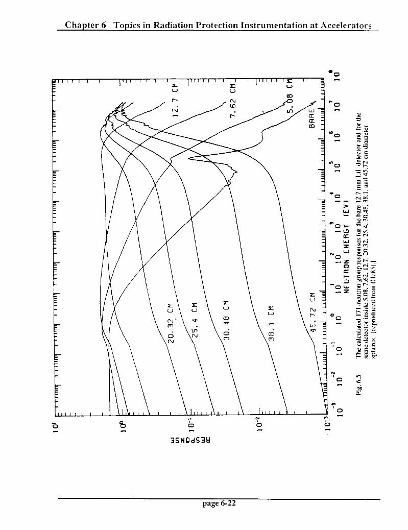
Chapter 6 Topics in Radiation Protection Instrumentation at Accelerators
3SNDdS3U
page 6-22

Chapter 6 Topics in Radiation Protection Instrumentation at Accelerators -
A Bonner sphere determination of the neutron specrtum is comprised of a set of measurements of the responses for the different spheres of radius r, Cr, where r has the discrete values based on the available set. Such responses will be given, ideally, by,
c, = s 0m g Ri.(E)dE, (6.26)
where dN/dE is the differential neutron flux density (the neutron spectrum) and R,(E) is the energy-dependent response function for the sphere of radius r. One measures C, and knows R,(E) with the objective of determining dN/dE by “unfolding” the spectrum. In practice, one works with a discrete approximation to the integral;
C, = F g RiEi)AEiv 1
(6.27)
where the index, i, labels each member of the set of “energy groups” used. The unfolding procedure is a difficult mathematical problem that, unfortunately, suffers from being underdetermined and ill-conditioned mathematically. (One has as many as 3 1 or more “unknowns” corresponding to 31 energy groups, with typically only 8 or 9 measurements to determine the response!) A variety of numerical techniques have been developed to do the unfolding.
Prominent codes in use at accelerators include BUNKI (Lo84), LOUHI (Ro80), and SWIFT (O’Br81). The first uses an interative recursion method and the second uses a least squares fitting procedure with user-controlled constraints. One essentially starts with an “educated guess” at the spectrum and interates to fit the responses. As we have seen, a l/E spectrum is a good starting point for an accelerator spectrum. SWIFT is different; it is a Monte-Carlo program that makes no a priori assumptions on the spectrum and can thus provide a “reality check” on results using the other two. It has the disadvantage in that it is known to sometimes produce nonphysical peaks in the unfolded spectrum. In general, the codes agree best with each other for those properties that are determined by integrating over the spectrum such as the average quality factor, total fluence, and total absorbed dose and dose equivalent. Typical spectra obtained from such unfolding procedures have been reported at a number of laboratories. Fermilab results have been summarized in (COSS) and are, in general, similar to those obtained at other laboratories. (See Chapter 4 for discussion of results of Fermilab neutron measurements.)
It is sometimes important to verify the “reasonableness” of the unfolded spectrum. Comparisons can be made with known spectra from radioactive sources such PuBe or AmBe and such comparisons have been made in, for example, (Co88). Sometimes, the normalized responses, Cr, themselves can be used to check the reasonableness of the unfolded spectrum. For example, in the labyrinth measurement [(Co85b) and (Co88)] and in the iron leakage measurements at Fermilab [(CoSS) and (E186)], such plots were made. These are shown in Fig. 6.6 taken from (Co85b) and Fig. 6.7 taken from (E186).
The labyrinth responses are compared with the sphere responses for a pure thermal neutron spectrum. The enhanced responses for the intermediate-sized spheres indicates the somewhat “harder” unfolded neutron spectrum than was observed. For the iron leakage spectrum, one can see evidence for the “softening” of the spectrum after the concrete was added. (See Chapter 4 for discussion of the dramatic spectral changes after the addition of concrete.) Other “verifications”, of course can be obtained using entirely independent measurement techniques.
page 6-23 -

Chapter 6 Topics in Radiation Protection Instrumentation at Accelerators -
c
I I I I I I
PI : / / I I 0
./
IX /
&
,:::-I
/ /
E / / i
8 k
0 m!
ii ,&
m /
,= //’ /’ /’
.’ .’ .. ..
\ 1
// ,/F%
/0= F
.M F u
\
‘7 \ \ \ \ \ . \ I I I I
‘\ \ 1 I I
z z 0.J 0.J 0
0 0 0 0
F \ .
3SNOdS38 03fllt’W8ON
lauuDq2 , SlUr-lO~ t
/
/’ 0
/ /
asuodsag p~ZllDUJlON
page 6-24

Chapter 6 Topics in Radiation Protection Instrumentation at Accelerators
In the use of hLiI(Eu) scintillators in such detectors in mixed fields, there are situations in which the signals from photons and/or muons can overwhelm the neutron signal. Awschalom and Coulson (Aw73) have developed a technique in which the eLiI is surrounded by plastic scintillator. A schematic diagram of the electronic readout circuitry, a schematic of the phoswich detector, and a typical pulse height spectrum obtained by use of this detector in a lc’ng exposure to environmental neutrons are given in Figs. 6.8, 6.9, and 6.10, respectively, all taken from (Aw73). The same detector was used to produce the pulse-height spectrum shown in the inset in Fig, 6.6.
In this technique, the fast discriminator is set to respond to the 2-3 nsec decay time of the plastic scintillation signal while the other discriminator is set to respond to the 1.4 psec decay time of the crystal. Selecting the slow counts not accompanied by fast counts clearly gives superior discrimination against non-neutron events from environmental radiation to which both the crystal and the plastic scintillator are sensitive.
In performing Bonner sphere measurements in neutron fields that are suspected of being nonuniform in space, it may be necessary to measure C, over the set of spheres individually because arranging them in an array may result not only in undesired “cross-talk” between the moderators but also in the need to make corrections for the non-uniformities of the radiation field.
Since accelerator neutron fields are often quite similar to each other, it was noticed that the choice of a single moderator size might well offer the opportunity to construct a “rem-meter” that would use a given sphere response function particularly well matched to energy depencence of the fluence-to-dose equivalent conversion factor. The standard implementation of this is in the development of the Andersson-Braun detector (An62) which uses a BF3 detector. The use of such counters is reviewed in (T’h88). At present, an ion chamber version of this instrument is used at CERN. Generally, the 25.4 cm (10 inch) diameter polyethylene sphere has been selected because its response curve provides the best match to the curve of fluence-to-dose equivalent. Hofert and Raffnsoe (Ho80) have measured the dose equivalent response of such an instrument as a function of neutron energy. Their results are displayed in Table 6.7.
Table 6.7 Dose equivalent response and measurement errors for 25.4 cm diameter sphere as a function of neutron energy . [Adapted from (HkW).]
En Dose Equivalent Response Error
(MW (10-S c sv-1) (%Io)
thermal 0.349 0.0245 3.209 0.1 1.335 0.25 1.082 0.57 0.923 1.0 0.845 2.5 0.784 5.0 0.653
15.5 0.348 19.0 0.445
280.0 0.157
10.0 12.1 6.8
s.; 5:2 6.1
z-z 12:2 10.1
page 6-25

Chapter 6 Topics in Radiation Protection Instrumentation at Accelerators
,,,!I / I I I”“” ’ ’ I”“” ’ 1 s
f -s E - :
;i “f
6
-s
/1111 I 1 I,,,,, I , , I,,,,,, , , Q -0
14hH aSI&,
. . 5 c:
c &’ ‘F Ex cc .ii x-3 E 3 E 3
7 c?zg ‘2 cj ez c -- .- z;r: y .‘J 1 _ 9. 5 p % r. c g
page 6-26

Chapter 6 Topics in Radiation Protection Instrumentation at Accelerators
These results are discussed further in (Th85). Generally, commercial versions of this instrument operate in the proportional counter mode. This renders them suspect in accelerator fields with high instantaneous dose rates that arise because of the small “duty factor” due to pulsed beams. A similar detector has been developed by Hankins and employed 6LiI(Eu) as the detector (Ha62). Hankins obtained the response shown in Fig. 6.11 compared with the “Inverse of the Radiation Protection Guide (RPG) curve”. [This figure is also found in (Kn79).] In the keV region, comparisons are difficult and there is some evidence that the detector overresponds considerably. However, the “match” was verified at thermal neutron energies. An alternative detector of this type has been developed by Leake (Le68). In this detector a 3He proportional counter is used in a 20.8 diameter sphere to reduce background due to photons along with a cadmium filter against thermal neutrons. It is claimed that this detector is effective in photon fields as high as 20 R/h. There are concerns that above 10 MeV this type of instrument serocsly underestimates neutron dose equivalent rates.
It is not necessary, for radiation protection purposes, that a “spherical” moderator be an exact sphere. Awschalom (Aw72) demonstrated that an octagon of revolution (a “pseudosphere”) having volume equivalent to that of a 25.4 cm diameter sphere had a response indistinguishable from that of the 25.4 cm sphere as a function of polar angle and that the response of a cylinder of equal volume was not far different This feature was investigated because cylinders and pseudospheres are cheaper to produce than spheres.
11’
10.
E
z 9’
Fi < 8,
c
‘g 7,
z
8 6,
5 8 m 5’
: 48
m > E 3,
z v
2
-
-
-
-
-
- .’ Inverse of RPG curve
l- 0.227 Thermal response
0.225 Inverse RPG
01 - h ” 1WkeV
Neutron energy
1 .O MeV 1OMeV
Fig. 6.11 Sensitivity of a 25.4 cm (10 in.) diameter moderating sphere surrounding a 4 mm X 4 mm Lil scintillator. Also shown is the relative dose per neutron labeled as “Inverse of RPG curve”. [Reproduced from (Kn79 as adapted from (Ha62j.l
page 6-27
Chapter 6 Topics in Radiation Protection Instrumentation at Accelerators
Lonp Counters
Another type of moderated neutron detector that has been used extensively is the 1onP countel; The idea is to adjust the configuration of moderators around some thermal neutron detector in such a manner as to assure that the detection efficiency plotted as a function of neutron energy is a straight line. It has has been found over the years that the best detector is a cylinder of moderating materials surrounding a thermal neutron detector (also cylindrical) on the axis. Snce a cylindrical detector is desired, the BF3 proportional counter is the most popular. One end of the cylinder “views” the neutron source for best results. Hanson and McKibben (Ha47) were the pioneers of the technique.
An improved version, which has rather widespread use, is that developed by J. DePangher and L. I. Nichols (De66). Figure 6.12 taken from (De66) shows the layout of this detector. The length and diameter are both approximately 41 cm and the mass is about 45 kg. The neutrons are to be incident on the “front” face.
Perhaps the best calibration data on this device is that of Slaughter and Rueppel (S177). They used filtered beams from a reactor (2 keV) as well as monoenergetic neutron beams from (p, n) and (d, n) reactions at accelerators to cover the energy range from 10 keV to 19 MeV. The sensitivity data resulted in an average of about 3.5 counts/(n cm-z) over this large dynamic range as indicated in Fig. 6.13 taken from (S177). [Fig. 6.13 also shows data from other workers as discussed in (S177)].
This detector has been used to conduct studies of skyshine at Fermilab [(Co85a) and (E186)]. The large peak in the pulse-height spectrum of the BF3 tube from thermal neutron capture (Q- value = 2.79 MeV) renders the detector essentially dead, with the application of a suitable discriminator, to all other radiations.
Knoll (Kn79) summarizes results with modified long counters that have achieved better uniformity and sensitivity over more restricted energy domains.
page 6-28

Chapter 6 Topics in Radiation Protection Instrumentation at Accelerators
Rlrr Cdkm
-? \
Brass EFjTube
I. I. I. I. ;. ;. :‘._ :‘._ ,,,_I ,,,_I .I., .I., ..,.‘; ..,.‘; Aluminus Liner ,, ‘.,z’:‘: ;: ‘. ,. . ..: ., .” I
- LA\ I
Aluninrm liner for SmJrct ttdu
\L sm... m ~~
outu P0lyBhykw
ShicM
Potptnytcnr -COM
\ front Cdmium
Shield
Fig. 6.12 Sketch of DePangher Long Counter. This version contained a built-in PuBe source. [Reproduced from Deli).]
“E 5 . s 5 s I ,x ..-- w c, .C * c L!?
6.0
5.0
4.0
3.0
2.0
1.0
- -
I I - -
l 0
0 0 l OA
+ $.Qe l o 8 �* 28
0 -cm 0 A
0 l This work A Ref. 4 ORef. 1 o Ref. 7 ORef. 3 +Ref. 8:
1o-2 10-l l
E�
- Mev
Fig. 6.13 Sensitivity [counts/(n cm-2)] as a function of neutron energy. [Adapted from (S177) and references cited therein.]
page 6-29

Chapter 6 Topics in Radiation Protection Instrumentation at Accelerators
Activation and Threshold Detectors
As we have seen, certain nuclear reactions have sharp thresholds which can be used to determine portions of a hadron spectrum that exceed it since the “leveling off’ of the cross sections is generally “well-behaved”. Of these, the production * ot “C is one of the best known and has t’he
cross sections shown in Fig. 6.14 taken from (Sw90). In addition to information on reaction thresholds provided in Chapter 4, where referral was made to threshold techniques, Table 6.8 taken from (Sw90) summarizes some of the useful reactions. [(Pa73) contains a large list of other reactions that might have useful thresholds.]
I -\ ,/ Proton
1c 1c 0 0 01 01 01 01 1 1 10 10 100 100
Kinetic energy (GeV)
Fig. 6.14 Excitation functions for the reactions ‘*C -> t ‘C induced by neutrons, pions, and protons. The arithmetic mean of the positive and negative pions cross-sections is shown as the pion curve. [Reproduced from (Sw90) as adapted (SW).]
Table 6.8 Types of activation threshold detectors. [Reproduced from Sw90).
TYPES OF ACTIVATION THRESHOLD DETECTORS
Rclftion Sample type Threshold (MeV)
,ZS-“P
"AI-'-Mg “.41-2’Na rA]-“Na
‘-hl- *F .PF-i8F
“c-xc
y--Be
Bi fission
Sulfur powder or pellets
Aluminum disks or pellets
Aluminum disks or pellets
Aluminum disks or pellets
Alummum disks or pellets
Teflon cylmders
Polyethylene cylinders or plastic cylinders
Polyethylene cylinders or plastic cylinders
Fission chamber
3 3 6
35
35 I?
‘0
35 50
page 6-30

Chapter 6 Topics in Radiation Protection Instrumentation at Accelerators
The 1% -> 11C producing reactions are of special interest because of the fact that plastic scintillators can themselves become activated by hadrons (especially neutrons and protons) exceeding 20 MeV. This technique was first developed at the Lawrence Radiation Laboratory by McCaslin (McC60). Stevenson (St84) has determined that a value of 28 fSv m* is an appropriate multiplicative factor for the conversion of the measured fluence of neutrons with E,, > 20 MeV (neutrons m-2) to the dose equivalent due to those energetic neutrons. This assumes a “typical” accelerator spectrum in side shields of earth or concrete where neutrons clearly dominate. Such measurements can be useful to determine the contribution of the high energy (E, > 20 MeV) neutrons to the total neutron dose equivalent.
Moritz (Mo89) has found that the use of hTE102A scintillators activated by the lq(n, 2n)llC can be included as an “additional detector” in a Bonner sphere measurement in order to extend the energy range. Moritz, following Stevenson, used an average cross section of 22 mb for the l2C(n, 2n)llC reaction. of 1.032 (Kn79).
NE102A has a carbon content of 4.92 X 1O22 atoms/gram and a density Moritz used a cylindrical detector 5 cm in diameter by 5 cm long and
achieved an efficiency of 93 % in detecting the 0.5 11 annihilation y-rays produced as a result of the l*C decay. In effect, the addition of this reaction reduced the degeneracy of the spectrum unfolding process using the code LOUHI (see Chapter 3).
Pertinent information, including some practical detector sizes for commonly used threshold reactions, are given in Table 6.9. Table 6.10 taken from (Sw90) gives a more extensive list of pssible threshold reactions. The Hg -> 149Tb reaction is a suitable monitor for very high energy particles and is sometimes used as a beam calibrator. However, it has been found by S. Baker [(Ba84) and (Ba91)] that there are three reactions involving copper targets which are more useful for this purpose becaue they have longer half-lives than the 4 hours of 149Tb. These cross sections have been measured for energies from 30 to 800 GeV and are included in Table 6.9.
page 6-31

Chapter 6 Topics in Radiation Protection Instrumentation at Acceleratoirs
Table 6.9 Important characteristics of various activation-detector techniques
Detector Reaction Energy Half-Life Typical Cross Sections Particle
bee Detector Size Peak High Energy Detected
(MeV) (mh) tmh) (mb)
sulfur 32S(n,p)32P >3 14.3 d 2.54 cm diam, 500a 1Oa P-
4 g disk
Aluminum 27Al(n,cL)24Na >6 15h 16.9 to 66OOg Ilb 9b Y
Aluminum 27Al(n,2p4n)22Na >25 2.6 y 16.9 g 3ob lob Y
Plastic l*C(n,*n) l lC >20 20.4 13 to27OOg 9ob 30b P+VY
scintillator min
Plastic 12C(n,spall)7Be >30 53 d 16.9 g (2.54 lgb
scintillator cm high)
Mercury 198Hg(n,spa11)149Tb Z&IO
Gold foils 197Au(n, ~pall)~~~Tb x%0 4.1 h 2.54 cm diam, 1.6b
aS wanson and Thomas (Sw90)
bBarbier (Ba69)
CBaker, et al (Ba91) and (Ba84).
page 6-32

Chapter 6 Topics in Radiation Protection Instrumentation at Accelerators
OD OD
s+ s+ g g 4 4 - -
n n 09 09 Q Q ~o*--na~aononnnof.4n ~o*--na~aononnnof.4n ormryci ormryci ri ri r; r; r;&rrri*;--rjtid r;&rrri*;--rjtid 2 2 ri ri ndr, ndr, s s
-- -- - - - - - - - - - - 0 0
page 6-33

Chapter 6 Topics in Radiation Protection Instrumentation at Accelerators
Fission Counters
The fission reactions described above have been exploited as neutron (or hadron) detectors at accelerators. In addition, other elements, not normally thought of as “fissionable”, exhibit significant fission cross sections. Figure 6.15 taken from (Pa73) shows the excitation functions of some of these materials. Fission of *mBi is expecially interesting since this reaction has a threshold of about 50 MeV and also exhibits strong evidence that the neutron and proton-induced fission cross sections are approximately equal. Bismuth has been employed in ionization chambers where the large ener y deposited by the fission fragments gives a clear “signature” of this process. Like the use of 1 C, it can provide further information about high energy neutrons B
and resolve ambiguities in the unfolding of spectra from Bonner sphere data. McCaslin, et.al. has summerized results obtained at the Lawrence Berkeley Laboratory (McC68).
Natural uranium
s-?\ Natural thorurn
I
1'
01 1 10
Energy (GeV)
100
Fig. 6.15 Fission cross sections of natumi uranium, natural thorium, bismuth, gold, and tantalum as a function of neutron or photon energy. [Reproduced from (Pa73).]
page 6-34

Chapter 6 Topics in Radiation Protection Instrumentation at Accelerators
Proton Recoil Counters
Knoll (Kn79) describes a variety of techniques for detecting neutrons based upon measuring the energy of recoil particles. The jHe(n,p)‘H reaction has a reasonable cross section even into the MeV region but suffers from competition with (n, d) processes and elastic scattering. Elastic scattering of neutrons in which the energy of the recoil particle is measured and correlated with the neutron energy has received a great deal of attention. The most obvious recoil particle to measure is the proton because hydrogenous detector materials (e.g., plastic scintillator) are readily available and also because the proton can receive the most energy in the recoil process. Detector designers have been able to exploit the fact that scattering from hydrom in the region En < 10 MeV is iso@epic in the center of mass frame. In (Kn79) it is shown that the probability, P&), of creating a recoil with energy & is also independent of angle in the laboratory frame within this energy domain. Thus the recoil energy is only a function of the incident neutron energy. However, complexities enter the picture because in scintillators, carbon is present along with the hydrogen and can contribute recoil protons. Furthermore, the magnitude of the cross sections is a function of neutron energy as is the efficiency of neutron detection in the scintillator. These effects, along with finite pulse height resolution, can lead to the need to resort to unfolding techniques, discussed in detail in (Kn79), in which the pulse height, indicative of the energy of the recoil proton, is correlated with the average neutron energy which could produce such a pulse. The technique has exhibited some promise in measuring the energy spectra of neutron radiation fields. The best recent summary is that of Griffith and Thorngate (Gr85) who were able to determine neutron energy spectra in the 2-20 MeV region.
TEPCs and LET Spectrometry
In mixed field dosimetry, a promising technique, now reaching commercial potential is that of the tissue-equivalent proportional chamber (TEPC) sometimes referred to as the “Rossi counter” after its inventor, H. Rossi (Ro55). These have been described by Brackenbush, et al in (Br78). In this chamber, tissue equivalent walls are employed to apply the Bragg-Gray principle. In such chambers, the pressure is maintained at low values, only a few torr (a few hundred pascals) so that the energy deposited is kept small. Thus, the energy so deposited will be equal to the linear energy transfer of the particle multiplied by the path length. At these low pressures, the gas- filled cavity has the same mass stopping power as a sphere of tissue of diameter about 1 pm- hence an “equivalent diameter of 1 l.tm”. In principle, determining the absorbed dose from events in such chambers is a straightforward unit conversion from a measured pulse height spectrum (calibrated in energy) to absorbed dose (in tissue) irrespective of the radiation field:
D(rad) = (1.602 X lo- *)C 2 (hN(h)]
PV h, (6.28)
where the summation is over channels corresponding to the radiation type of interest (see below), V is the sensitive volume (cm3), p is the density (g/cm3) and C converts the channel number to energy in MeV while h is the channel number and N(h) is the number of counts in channel number h.
In such chambers, the transition between photon and neutron induced events occurs at a pulse height of about 15 keV/pm. It is possible to determine the quality factor, Q, from a single TEPC measurement. Under the conditions stated above, one can unfold from the pulse height spectrum the distribution of absorbed dose as a function of LET, D(L), using a complicated formula derived by Rossi (Ro68). [The formula is complicated by the fact that one must average over mean chord lengths in the chamber.] Such a distribution is used to calculate quality factor, and
page 6-35

Chapter 6 Topics in Radiation Protection Instrumentation at Accelerators
hence the dose equivalent. The advent of microcomputers has now made such instruments feasible as portable instruments. Fig. 6.16 taken from (Br78) shows a typical pulse height spectrum for such an instrument. In higher energy fields, dose distributions due to other particles with the same characteristic shapes but larger pulse sizes appear as the 2H, 3H, 3He, 4He and even 7Li drop points. This obviously will add complexities to the unfolding procedures in the determination of LET spectra. A more recent discussion of the application of this technique is given by Vasilik et. al. (Va85). 1o6
1.4 MeV NEUTRONS
DOSE DISTRIBUTION. D(I)
EVENT DISTRI EmION. NIII
CHANNEL NUMBER
20 40 60 a0 im vo 140
Fig. 6.16 Pulse-height spe43ra from a tissue-equivalent proportional counter exposed to 1.4 MeV neutrons and 6oco y-rays. [Reproduced from (Br78j.l
Recombination Chambers
An adaptation of the ion chamber that has shown considerable potential for usefulness as a “mixed field” dose equivalent meter is based on the exploitation of recombination phenomena in such chambers. As charged particles interact in such a chamber the gas is ionized. The ions left behind in this process will be collected by the electrodes except to the extent that they recombine. Such “columnar recombination” will depend upon the distance between the ions as well as upon the applied voltage (which sets the speed at which the ions migrate to the electrodes). Thus, for a given voltage, a chamber should exhibit more severe recombination for the radiations having high LET (e.g. neutrons, heavy ions, etc.) than for those having low LET (electrons, photons, and muons). The initial work on this subject was done by Zielcyznski (Zi63). Later, Baarli and Sullivan (Ba65) further refined the topic. It turns out that the current, i (or charge if integrated over time), measured in a given radiation field, is related to the applied voltage V by the following approximate expression:
i = kV”. (6.29)

Chapter 6 Topics in Radiation Protection Instrumentation at Accelerators
The power, n, is approximarely proportional to the quality factor Q. The relationship is shown in Fig. 6.17 taken from (Sw90). Using a different chamber, workers at Fermilab were able to obtain very similar curves over a more limited range of Q (2 < Q < 7) using mixed fields of ‘y- rays and PuBe neutrons (Co84). The relationship between Q and n determined in (Co84) for a particular chamber used in this manner was
n = 0.00762 + 0.16Q. (6.30)
04 , / I I
03-
0.1 - Po-Be neutrons
14-MeV neutrons
: -&Ra gammas
0; l I I I I
0 4 a 12 16 20
Q
Fig. 6.17 Response of a.high-pressure pCarallel-plate recombination chamber as a function of quality factor Q. The curve shows the response predicted from theory. The experimental points were reported by Baarli and Sullivan (Ba65). [Reproduced from (StiO).]
At Fermilab, the normalized response (usually using some adjacent ion chamber) is measured as a function of time for the special chamber provided for the purpose over the voltage range 20 I V 2 1200 volts. The method of least squares is then applied to determine n by taking advantage of the fact that the above relarionship can be rewritten as
In (i) = In(k) + n In (V). (6.3 1)
In typical situations, this log-log fit is of moderately good quality. The quality factor, Q, then, can be determined directly from n using the above “calibration”. Data taken in the process of investigation of the iron leakage spectrum described by Elwyn and Cossairt (E186) where the spectrum was “softened” after the addition of concrete to the bare iron shield are shown in Fig. 6.18 taken from (E186). The spectra in which these measurements were made are Spectra E and F shown in Fig. 3.25. Fig. 6.19 taken from (Co87) shows the response measured in a field known to be dominated by muons (Q = 1).
These measurements have been used to check the quality factors obtained in the unfolding of Bonner sphere data. Table 6.12 taken from (Co88) illustrates the good agreement between these entirely different techniques.
page 6-37

Chapter 6 Topics in Radiation Protection Instrumentation at Accelerators
2 10
t
' . l * a.*. . - l � -+- - .
?
. . . . 9 . . l .
i
; 08
2 �i,.
(1992047) ⌧ lo-2
k
F
OF= 105 t 026
2 06
CHAMBER POTENTI AL ( VOLTS)
Fig. 6.19 Recombination chamber response as a function of chamber potential in a radiation field nearly purely due to muons. meproducded from (Co87).]
- 0.0 ii
j
5 1.0; IF7 i
ht3c . uz c
OF= 3.00 t 0.27
: 0.6+’ 1
5 - AFTER
=, 0.4c Y
0.2 k -1
t 1 I1 ,,,,I i 1 I111111
100 IO00
CHAMBER POTENTIAL
(VOLTS)
Table 6.11 Average Quality Factors. The spectra are those of Figs. 3.24,3.25, and 3.26. [Reproduced from (G&8).]
Spectmm Tecbaique
D 1.4 1.4 f 0.2+ 0.2+ 1.1 LO.3 l
E 5.4 5.4 & 0.2 0.2 6.0 6.0 f. 0.6 0.6
F 2.5 2.5 f 0.3 0.3 3.0& 3.0& 0.3 0.3
I 3.1 3.1 f 0.7 0.7 3.4 3.4 f 0.1
Fig. 6.18 Recombination chamber response functions measured both before (top) and after (bottom) the placement of additional shielding [see Spectra E and F of Fig. 3.251. Values of the quality factor Q are obtained from the fitted N-values according to Eq. (6.30). lReproduced from (E186).]
page 6-38

Chapter 6 Topics in Radiation Protection Instrumentation at Accelerators -
Early work was done by Zel’chinskij and Zharnovetskij (Ze67) in which they proposed using two chambers placed in the radiation field of interest, one operated at a low voltage and other at a high voltage. The differences in currents read out by the two chambers would then be proportional to the dose equivalent rate. It turns out that measuring differences in small ion chamber currents found in practical chambers is difficult due to the small currents and connector leakage problems.
Hofert and Raffnsoe (Ho80) have measured the dose equivalent response of such an instrument as a function of neutron energy and obtained the results in Table 6.12.
Table 6.12 Dose equivalent response and measurement errors for recombination chamber as a function of neutron energy [Adapted from (HSO).] En Dose Equivalent Response Error MeV) (10-S c sv-1) (%)
hermal 0.830 0.0245 2.579 0.1 1.451 0.25 1.585 0.57 1.215 1.0 1.215 2.5 1.112 5.0 0.840
15.5 0.728 19.0 0.998
!80.0 0.782
10.0 12.1 6.2 6.1 5.2
2:: 5.2 5.2
12.1 10.1
These responses turned out to have the smallest dependence on energy of any of tl tested by Hofert and Raffnsoe and the results for which were reported in (Ho80)
instruments
Counter Telescopes
Since the fluence-to-dose equivalent conversion factor for muons varies so little over a wide range [as discussed in Chapter 1 and determined by Stevenson, (St83)], scintillation telescopes provide an attractive method for assessing pure muon fields. At suitable distances and at forward angles, muons will dominate the radiation fields and the results is that little or no discrimination against other particles is necessary.
At Fermilab, a pair of 20.32 cm square by 0.635 cm thick plastic scintillators has been constructed (Co83). The separation distance between theses “paddles” provides moderate directional sensitivity when a coincidence is required between the two plates in a relatively parallel beam of muons. A 2.54 cm thick aluminum plate is employed in the gap between the plates to reduce false coincidences due to &rays (recoil electrons) from the collisions occurring in the first plate. These plates are mounted in a four-wheel drive vehicle (called the Mobile Environmental Radiation Laboratory-MERL) and are supported by an on-board gasoline- powered generator. A microwave telemetry system provides gating pulses and proton beam intensity information so that normalized beam-on and beam-off (background) measurements can be taken simultaneously. The paddles were chosen to provide sufficient sensitivity to obtain statistical errors at the 20 % level in remote locations receiving annual dose equivalents in the fractional mrem range in a scan lasting an hour or two. In such a scan, the detectors are moved across a region of elevated muon flux density. In these detectors, a muon beam perpendicular to
page 6-39 -

Chapter 6 Topics in Radiation Protection Instrumentation at Accelerators
the detectors yields 1.7 X IO-5 counts per minute per mrem/hour. The normal singles background due to cosmic rays is approximately 400 counts per minute.
Smaller, more portable systems can be useful in conducting muon surveys. Fermilab has such a system, called a “muon finder”, consisting of a pair of small plastic scintillators mounted in a compact package which is battery powered and can be carried by one (athletic!) person. It is read out by scalers and can record both singles and coincidence rates. The ratio of the two can be used to “find” unknown muon sources; hence the name of the detector. Also, the separation distance can be adjusted to enhance, or limit, the directional sensitivity.
The parameters of this system are given in Table 6.13.
Table 6.13 Parameters of “muon tinder” used at Fermilab
Scintillator diameter 2.1 cm Scintillator thickness 0.635 cm Scintillator area 3.6 cm2 Scintillator spacing 0.5 to 8.9 cm Half-angle cone of sensitivity 0.9 to 0.2 radians (51 to 11.5 deg. half-angle) Dose calibration factor (muons I detetectors) 90 muons/prem Dose rate cal. factor (muons I detectors) 25 muonsLsec per mrem/hour
Of course, the use of such scintillators, especially in the “singles” mode, in mixed fields of muons and neutrons requires that one must be aware of the fact that the plastic scintillators have nonzero detection efficiency for the neutrons. Vylet (Vy91) has used the values of total cross sections to calculate the neutron detection efficiency of the detectors described above for neutrons over a range of energies. The results are given in Fig. 6.20 taken from (Vy91). In this figure, effects due to successive collisions as well as those due to the first collisions (” 1st collision with H”) are given. The total efficiencies at the upper end of the energy region measured were an efficiency of 0.058 for the MERL paddles and 0.0235 for the muon finders.
0.8 0.8
)r )r 0.6 0.6 0 c Q) .- l z z 0.4 0.4 - -
iii iii
- MERLpadde-1staAisionwithH - - - - - MERL paddle - total
- Muon gun - 1st collision with H Muon gun - total
loo loo IO' IO' 10"
E WeVl
Fig. 6.20 Calculated neutron efficiencies as a function of neutron energy of scintillation counters used in the “singles” mode at Fermilab. [Reproducded from (Vy!Jl).]
page 6-40

Chapter 6 Topics in Radiation Protection Instrumentation at Accelerators -
References
(An62)
(APW
(Aw72)
(Aw73)
(Aw85)
(Ba65)
(Ba69)
(Ba84)
(Bag1 )
(Br60)
(Br78)
(Ce69)
(Co83)
(Co84)
(Co85a)
(Co85b)
(Co87)
page 6-41 -
I. 0. Andersson and J. Braun, “A neutron rem counter”, Nucleonik tj (1963) 237 and I. 0. Andersson and J. Braun, “A neutron rem counter with unifirom sensitivity from 0.025 MeV to 10 MeV”, Neutron dosimetry, (Proc. Symp. Harwell, 1962) vol. 2, p.87.
R. E. Apfel, “The superheated drop detector”, Nucl. Instr. and Meth. 162 (1979) 603-608.
M. Awschalom, “Bonner spheres and tissue equivalent chambers for extensive radiation area monitoring around a l/2 TeV proton synchrotron”, in Proceedings of IAEA Symposium on Neutron Monitoring for Radiation Protection Purposes (Vienna, 1972, vol 1, p. 297).
M. Awschalom and L. Coulson, “A new technique in environmental neutron spectroscopy”, in Proc. of the Third lntemational Conference of the lntemational Radiation Protection Association, Washington, DC, 1973 (U. S. Atomic Energy Commission, Technical Information Center, Oak Ridge Tennesses, CONF 730907-P2).
M. Awschalom and R. S. Sanna, “Applications of Bonner Sphere detectors in neutron field dosimetry”, Rad. Prot. and Dosimetry jj2 (1985) 89-l 01.
J. Baarli and A. H. Sullivan, Health Physics 11 (1965) 353.
M. Barbier, Induced Radioactivity, (North-Holand Publishing Company, Amsterdam and London, Wiley Interscience Division, John Wiley and Sons, Inc, New York, 1969).
S. I. Baker, C. R. Kerns, S. H. Pordes, J. B. Cumming, A. Soukas, V. Agoritsas, and G.
R. Stevenson, “Absolute cross section for the production of 24Na in Cu by 400 GeV protons”, Nucl. Instr. and Meth. A222 (1984)467-473
S. I. Baker, R. A. Allen, P. Yurista, V. Agoritsas, and J. 8. Cumming, “Cu(p,x)24Na cross section from 30 to 800 GeV”, Phys. Rev. C 43 (1991) 2862-2865.
R. L. Bramblett, R. I. Ewing, and T. W. Bonner, “A new type of neutron dosimeter”, Nucl. Instr. and Meth. 9 (1960) 1-12.
L. W. Brackenbush, G. W. R. Endres, and L. G. Faust, “Measuring neutron dose and quality factors with tissue-equivalent proportional counters”, in Advances in Radiation Monitoring, Proc. of a Symposium (IAEA, Stockholm, 1978).
H. Cember, lnrroducrion to Health Physics, (Pergamon Press, New York, 1969).
J. D. Cossairt, “Recent muon fluence measurements at Fermilab”, Health Phys. 45 (1983) 651-658.
J. D. Cossairt, D. W. Grobe, and M. A. Gerardi, Fermilab Report TM-1248 (1984).
J. D. Cossairt and L. V. Coulson, “Neutron skyshine measurements at Fermilab”, Health Physics 48 (1985) 171-181.
J. D. Cossairt, J. G. Couch, A. J. Elwyn, and W. S. Freeman, “Radiation measurements’ in a labyrinth penetration at a high-energy proton accelerator”, Health Phys. Q (1985) 907-917.
J. D. Cossairt and A. J. Elwyn, “Personal dosimetry in a mixed field of high-energy muons and neutrons”, Health Physics g (1987) 813-818.

Chapter 6 Topics in Radiation Protection Instrumentation at Accelerators -
(Co88)
(DeP66)
(E186)
(F@4)
(Ge83)
(G@5)
(Gt-87)
(Ha47)
(Ha62)
(He85)
(Ho80)
(H684)
(ln84)
(Kn79)
(Ko85)
(Le68)
J. D. Cossain, A. J. Elwyn, W. S. Freeman, W. C. Salsbury, and P. M. Yurista, “Measurement of neutrons in enclosures and outside of shielding at the Tevatron”,
Fermilab-Conf-881106 (1988) also in Proceedings of the 22nd Midyear Meeting of the Health Physics; Topical Meeting on Insrrumenrarion, San Antonio, TX, December, 198i3, pp. 190-l 99.
J. DePangher and L. L. Nichols, “A precision long counter for measuring fast neutron flux density”, Pacific Northwest Laboratory Report BNWL-260 (1966).
A. J. Elwyn and J. D. Cossairt, “A study of neutron leakage through an Fe shield at an accelerator”, Health Physics 51 (1986) 723-735.
W. S. Freeman and F. P. Krueger, “Neutron calibration tests of Fermilab radiation detectors”, Fermilab Radiation Physics Note No. 48 (1984).
R. V. Griffith and L. Tommasino, in “Dosimetry for Radiological Protection at High Energy Particle Accelerators”, Chapter 1 in The Dosimerry of ionizing Radiation, Volume IV (Academic Press, 1990). [Figure taken from W.R. Nelson, et. al., CERN Report CERN- TIS-RP/lOO/PP (1983).]
R. V. Griffith, and J. H. Thorngate, “Neutron spectrometers for radiation monitoring at Lawrence Livermore National Laboratory”, Rad. Prot. and DOS. 1Q (l-4) (1985) 125-l 35.
N. A. Greenhouse, T. M. De Castro, J. B. McCaslin, A. R. Smith, R.-K. Sun, and D. E. Hankins, “An evaluation of NTA film in an accelerator environment and comparisons”, Radiation Protection Dosimetty 2p (1987) 143-147.
A. 0. Hanson and M. L. McKibben, “A neutron detector having uniform sensitivity from ;O keV to 3 MeV”, Phys. Rev. 72(1947) 673.
D. E. Hankins, Los Alamos Scientific laboratory Report LA-2717 (1962).
N. E. Hertel and J. W. Davidson, “The response of Bonner spheres to neutrons from thermal energies to 17.3 MeV”, Nucl. Instr. and Meth. a (1985) 509-516.
M. Hofert and Ch. Raffnsee, “Measurement of absolute absorbed dose and dose equivalent response for instruments used around high-energy proton accelerators”, Nucl. Instr. and Meth. 176 (443-448) 1980.
M. Hofert, “The NTA emulsion: an ill-reputed but misjudged neutron detector”, in Pacific Northwest Laboratory Report PNL-SA 12352 (CONF-8308140, 1984); alternatively, CERN Report TIS-RP/l 1 O/CF (1984).
H. Ing and H. C. Birnboim, “A bubble-damage polymer detector for neutrons”, Nuclear Tracks Radiation Measurements”, 8 (l-4) (1984) 285-288.
G. F. Knoll, Radiation Defection and Measurement, (John Wiley and Sons, New York, 1979).
T. Kosako, T. Nakamura, and S. lwai, “Estimation of response functions of moderating type neutron detectors by the time-of-flight method combined with a large lead pile”, Nucl. Instr. and Meth. a (1985) 103-122.
J. W. Leake, “An improved spherical dose equivalent neutron detector”, Nucl. instr. and Meth. s3 (1968) 329.
page 6-42 -

Chapter 6 Topics in Radiation Protection Instrumentation at Accelerators -
(Lo84)
(MCCGO)
(McC68)
(Mo89)
(O’br81)
(Ro55)
(Ro68)
(Ro80)
(Se81)
(Sl77)
(St83)
(St84)
(Sw90)
(Th85)
(Th88)
(Va85)
NY91 1
K. A. Lowry and T. L. Johnson, “Modifications to interative recursion unfolding algorithms and computer codes to find more appropriate neutron spectra”, U. S. Naval Research Laboratory Report NRL-5430, Washington, DC (1984) and L. W. Brackenbush and R. I Scherpelz, “SPUNIT: a computer code for multisphere unfolding”, in Proc. of the HealfIi Physics Society Topical Meeting on Computer Applications in Healrh Physics (Columbia Chapter of the Health Physics Society, Richland, WA, 1984).
J. B. McCaslin, “A high-energy neutron-flux detector”, Health Physics 2 (1960)399-407.
J. B. McCaslin, H. W. Patterson, A. R. Smith, and L. D.Stephens, “Some recent developments in technique for monitoring high-energy accelerator radiation”, In Proc. of the First lnremarional Congress of Radiation Protection: International Radiation Protection Association, Pergamon Press, new York Part 2 (1968) 1131-l 137.
L. E. Moritz, “Measurement of neutron leakage spectra at a 500 MeV proton accelerator”, Health Phys. 56 (1989) 287-296.
K. O’Brien and R. Sanna, “Neutron spectral unfolding using the Monte-Carlo method”, Nucl. Instr. and Meth. 185 (1981) 277-286.
H. H. Rossi and W. Rosenzweig, “A device for the measurement of dose as a function of specific ionization”, Radiology @ (1955) 404-411.
H. H. Rossi, “Microscopic energy distribution in irradiated matter”, Radiation Dosimerry Vol 1, F. H. Attix and W. C. Roesch, Editors (Academic Press, New York, 1968).
J. T. Routi and J. V. Sandbert, “General purpose unfolding LOUHl78 with linear and nonlinear regularization”, Computer Phys. Commun. 21 (1980) 119-144.
W. Seelmann-Eggebert,G. Pfenning, H. Miinzek, H. Klewe-Nebenius, lnstitut fur Radiochemie, Nuklidkarte (Chart of the Nuclides) Kernforschungszentrum karlsruhe GmbH, Karlsruhe, Germany (1981) (5. Aufluge)
D. R. Slaughter and D. W. Rueppel, “Calibration of a DePangher long counter from 2 keV to 19 MeV”, Nucl. Instr. and Meth. 145 (1977) 315-320.
G. R. Stevenson, “Dose and dose equivalent from muons”, CERN TIS Divisional Report TIS-RP/099 (1983).
G. R. Stevenson, “The estimation of dose equivalent from the activation of plastic scintillators”, Health Phys. 47 (1984) 837-847.
W. P. Swanson and R. H. Thomas, “Dosimetry for Radiological Protection at High Energy Particle Accelerators”, Chapter 1 in The Dosimerry of lonizing Radiation, Volume III (Academic Press, 1990).
R. H. Thomas and G. R. Stevenson, “Radiation protection around high energy accelerators”, Rad. Prot. and DOS. lo (1985) 283-301.
R. H. Thomas and G. R. Stevenson, “Radiological Safety Aspects of the Operation of Proton Accelerators”, Technical Report No. 283, IAEA, Vienna, 1988.
D. G. Vasilik, G. H. Erkkila and D. A. Waechter, “A portable neutron spectrometer/dosemeter”, Rad. Prot. DOS. 1p (No. l-4) (1985) 121-124.
V. Vylet, “Estimated sensitivity of the ‘muon gun’ to neutrons”, Fermilab Radiation Physics Note. No. 92 (1991).
page 6-43 -

Chapter 6 Topics in Radiation Protection Instrumentation at Accelerators
(Ze67) M. M. Zel’chinskij and K. Zharnovetski, “Differential recombination chamber”, Badan
Jadrowych Nuclear Research institute Report INR No. 739/X1X/D (Translated at CERN) (1967).
(Zi63) M. Zielczynski, Neutron Dosimetry (IAEA, 1963)Vol II, p. 397.
page 6-44 6-44
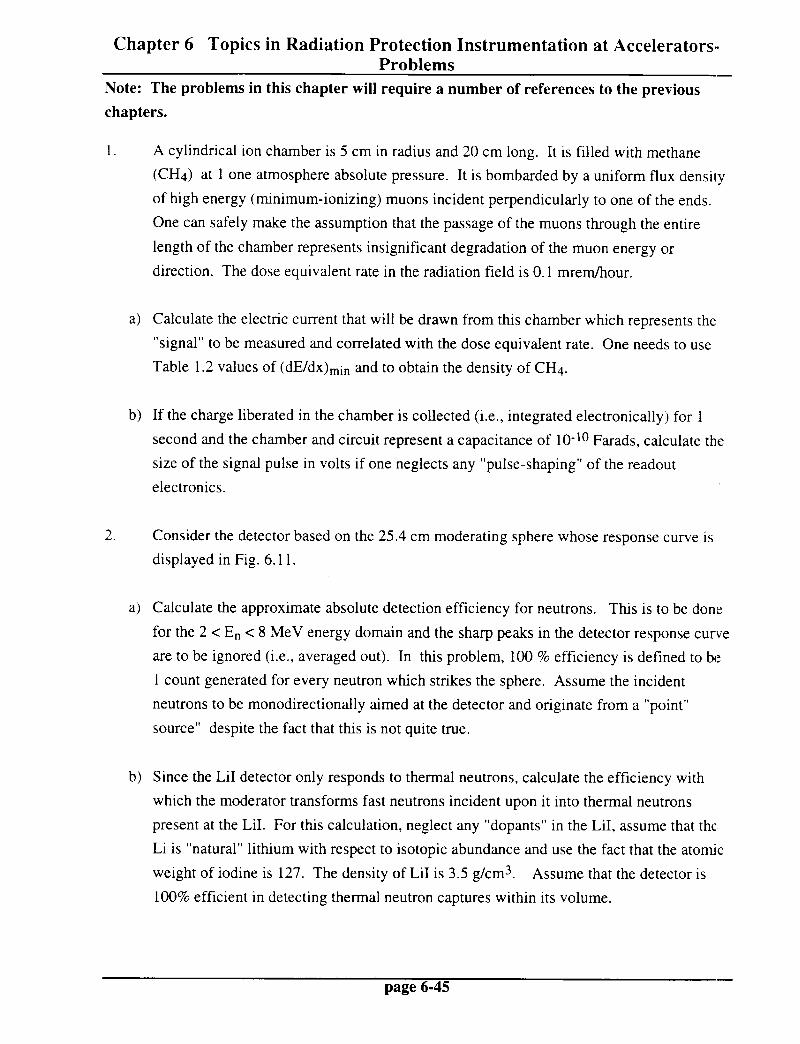
Chapter 6 Topics in Radiation Protection Instrumentation at Accelerators- Problems -
Note: The problems in this chapter will require a number of references to the previous
chapters.
1. A cylindrical ion chamber is 5 cm in radius and 20 cm long. It is filled with methane
(CH4) at 1 one atmosphere absolute pressure. It is bombarded by a uniform flux density
of high energy (minimum-ionizing) muons incident perpendicularly to one of the ends.
One can safely make the assumption that the passage of the muons through the entire
length of the chamber represents insignificant degradation of the muon energy or
direction. The dose equivalent rate in the radiation field is 0.1 mrem/hour.
a) Calculate the electric current that will be drawn from this chamber which represents the
“signal” to be measured and correlated with the dose equivalent rate. One needs to use
Table 1.2 values of (dE/dx),i, and to obtain the density of CH4.
b) If the charge liberated in the chamber is collected (i.e., integrated electronically) for 1
second and the chamber and circuit represent a capacitance of lo-lo Farads, calculate the
size of the signal pulse in volts if one neglects any “pulse-shaping” of the readout
electronics.
2. Consider the detector based on the 25.4 cm moderating sphere whose response curve is
displayed in Fig. 6.11.
a> Calculate the approximate absolute detection efficiency for neutrons. This is to be done
for the 2 < E, < 8 MeV energy domain and the sharp peaks in the detector response curve
are to be ignored (i.e., averaged out). In this problem, 100 % efficiency is defined to be
1 count generated for every neutron which strikes the sphere. Assume the incident
neutrons to be monodirectionally aimed at the detector and originate from a “point”
source” despite the fact that this is not quite true.
b) Since the LiI detector only responds to thermal neutrons, calculate the efficiency with
which the moderator transforms fast neutrons incident upon it into thermal neutrons
present at the LiI. For this calculation, neglect any “dopants” in the LiI, assume that the
Li is “natural” lithium with respect to isotopic abundance and use the fact that the atomic
weight of iodine is 127. The density of LiI is 3.5 g/cm3. Assume that the detector is
100% efficient in detecting thermal neutron captures within its volume.
page 6-45 -

Chapter 6 Topics in Radiation Protection Instrumentation at Accelerators- Problems
3. A BF3 proportional chamber is used in a DePangher long counter. This detector, when
placed in a certain neutron field known to he dominated by neutrons of approximately 5
MeV kinetic energy, generates counts due to neutrons at the rate of 1 count/minute.
The detector sensitivity is that represented in Fig. 6.13. The counter operates at one
atmosphere absolute pressure, the atomic weight of boron is 10.8 while the atomic weight
of fluorine is 19. At STP the density of BF3 is 2.99 grams/liter.
a) What is the dose equivalent rate of this radiation field?
b) If the radiation field persists full time, is this detector sufficiently sensitive to detect a
dose rate of 10 mrem/year?
c) In this radiation field, high energy minimum ionizing muons pass through this detector,
including the proportional counter. The largest muon signals in the proportional counter
will obviously result when the muons pass lengthwise through the tube. If the tube is 40
cm long, what will be the size of the largest muon-induced signal relative to the neutron-
induced signal ? Is it likely that a simple discriminator circuit can be used to eliminate the
muon-induced signals. It is quite permissable to “guess” the value of (dE/dx)min by
roughly interpolating among the values tabulated in Table 1.20.
4. One needs to understand the sensitivity of the technique of using the IzC(n, 2n)llC
reaction in plastic scintillator to measure dose equivalent rate external to thick concrete or
earth shielding near a high energy accelerator. The detector discussed in the text used by
Moritz has a sensitive volume of approximately 100 cm3 (a 5 cm diameter by 5 cm long
cylinder). The NE102A scintillator, from (Kn79), has a density of 1.032 g/cm3. This
detector is nearly 100 % efficient at sensing the 0.5 11 MeV annihilation photons
produced in the course of the 11C decay.
a) This detector is irradiated in a particular radiation field external to such accelerator
shielding. The irradiation, which is steady in time, is of sufficient length in time to result in
saturation of the production 01 ~ 1lC in the scintillator. After the beam is turned off, the
detector counts at a rate of 10 counts per minute (including appropriate decay-correc,tion to
the instant of beam shutdown). Calculate the flux density of neutrons with E, > 20 MeV
during the irradiation and use the result along with Stevenson’s conclusion concerning the
conversion from the flux density of neutrons with E, > 20 MeV to dose equivalent to
determine the dose equivalent rate.
page 6-46

Chapter 6 Topics in Radiation Protection Instrumentation at Accelerators- Problems
b) Assuming this count rate is the smallest that can be reliably detected, how much smaller in
volume can the detector be for it to barely be sensitive to a dose equivalent rate of 2
mrern/hour?
page 6-47 -

This page is intentionally left blank.