Chapter 5 Fuel Systems Part 1 - D. Abataabata.sdsmt.edu/pdf_files/ME419/Presentations/Chap 5 Fuel...
33
Chapter 5 Fuel Systems – Part 1 ME419 Thermal Systems Design D. Abata
Transcript of Chapter 5 Fuel Systems Part 1 - D. Abataabata.sdsmt.edu/pdf_files/ME419/Presentations/Chap 5 Fuel...

Chapter 5 Fuel Systems – Part 1 ME419 Thermal Systems Design
D. Abata

Air Flow
from compressible flow theory

Fuel Flow


Diesel: What and Why
1. Utilizes heavy fuel blends, less expensive(?)
2. Fuel has higher heating value on a volumetric basis
3. More efficient at part load
4. Higher compression ratio
5. Sturdier construction, more expensive
6. Lower speed
7. Higher torque, lower horsepower ratings
8. No spark system, rugged operation (?)
9. Problematic starting, particularly in cold weather
10. Characteristic odor

MAN Diesel SE (formerly MAN B&W Diesel AG) Cummins
Caterpillar

Classifications and Considerations 1. Size (bore, stroke, number of cylinders, torque, speed,
horsepower output, etc.)
2. Combustion chamber type (DI or IDI)
3. Two stroke, four stroke
4. Naturally aspirated, turbocharged
5. Fuel delivery system (low pressure and high pressure fuel metering)
6. Injector type (electronic, mechanical)
7. Spray pattern, spray penetration, droplet distribution
8. Rate of fuel delivery
9. Heat release of fuel
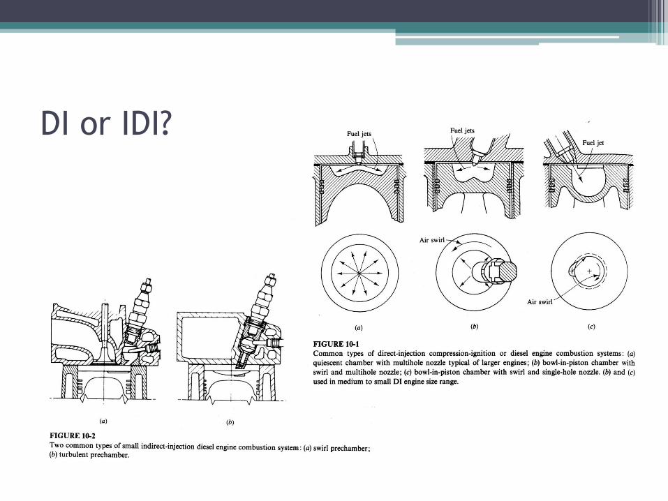
DI or IDI?


DI and IDI Comparisons
DI Engines
• larger bore
• turbocharged
• 2 or 4 stroke
• low speed
• lower compression ratio
• multi-hole injectors
• high pressure injection
IDI Engines
• smaller bore
• turbocharged
• 4 stroke
• high speed
• high compression ratio
• single hole injectors
• lower pressure injection

CI and SI Comparison

Fuel Delivery Types
• low pressure fuel metering
▫ jerk pump
in line
rotary (distributive)
• high pressure fuel metering
▫ common rail

Common Rail

Individual In-Line note: This is a jerk pump with
individual plungers. One plunger could also accomplish the task with some sort of fuel
distribution system (a fuel distributor)

Individual Unit

Individual Unit – mechanical fuel metering

Pintle Nozzle

Injection Pressures and Fuel Lines
15000 psi
22000 psi
Fig 6-31 (left) CR – common rail, EUI – electronic unit injector, PLI – pump –line - injector system

Effect of Compressibility

Heat Release

Fuel Delivery and Pressure
Development

Fuel Delivery and Pressure
Development • Ignition delay
• Premixed combustion phase
• Mixing controlled phase
• Late combustion phase
• Max cylinder pressure – about 1000 psia
(7MPa = 7000 kPa = 70 atm)
• Fuel injection timing 20 deg BTDC
• Injection duration 20 deg
• Note vaporization before premixed combustion phase

Fuel Delivery and Heat Release

Fuel Delivery and Heat Release
• Ignition delay
▫ Physical
▫ Chemical
• Engine Speed
• Engine Load
• Engine Temperature (cold start)
• Knocking in the CI engine

Heat Release

Heat Release
• Fuel injection across chamber with substantial momentum (a)
• Fuel deposition on chamber walls, limited evaporation at the onset of injection, rate controlled by diffusion of gasses at wall during combustion (b,c)

Ignition Delay 1. Injection timing – earlier injection causes increased ignition delay
2. Injection Quantity – higher load causes shorter injection delay
3. Intake air temp and pressure – increased temp and pressure shortens ignition delay
4. Engine speed – slight decrease in ignition delay
5. Wall effects – more fuel on walls increases ignition delay
6. Swirl - little effect
7. Oxygen concentration – increased oxygen levels, shorter ignition delay
8. Fuel properties – compact molecules increase ignition delay

Fuel Quality • Percentage of good fuel blended by a fuel with low ignition quality – Cetane
number
• Higher Cetane number fuels are less likely to knock (have short ignition delays)
• CN = % of n-cetane + 0.15 x % HMN
• Cetane = n- hexadecane
• HMN = heptamethylnonane
• Cetane number, like Octane number, higher the better, but for the opposite reason

Spray Characteristics

Spray Characteristics
1. Spray penetration
2. Spray angle
3. Droplet frequency distribution
4. Sauter mean diameter

Diesel Engine Emissions
• CO – not an issue (generally)
• CHx –sac volume, wall wetting, and incomplete combustion at high loads
▫ controlled through better injector design, load limiting strategies, and exhaust treatment with catalysis
• NOx –bulk gases due to high temperature combustion of premixed fuel and droplet combustion
▫ controlled through limited use of EGR and exhaust treatment with catalysis (SCR)
• particulate – agglomerated carbon particles from ‘improper’ combustion kinetics
▫ controlled through injection timing, injection pressure, and exhaust treatment (filtration and regeneration).

NOx and Particulate
NOx formation in the premixed phase
NOx formation in the droplet phase
oxygen
vaporizing fuel
flame
NOx – particulate tradeoff

End