Chapter 5 Enhanced Direct Memory Access (EDMA) DSK 1-day Workshop Student Guide DSK 1-day Workshop...
107
Chapter 5 Chapter 5 Enhanced Direct Memory Access Enhanced Direct Memory Access (EDMA) (EDMA) DSK 1-day Workshop Student Guide DSK 1-day Workshop Student Guide TMS320C6000 Peripherals (207- 289)
-
Upload
barnard-lang -
Category
Documents
-
view
232 -
download
8
Transcript of Chapter 5 Enhanced Direct Memory Access (EDMA) DSK 1-day Workshop Student Guide DSK 1-day Workshop...
Chapter 5Chapter 5
Enhanced Direct Memory Access Enhanced Direct Memory Access (EDMA)(EDMA)
DSK 1-day Workshop Student GuideDSK 1-day Workshop Student Guide
TMS320C6000 Peripherals (207-289)
Chapter 5, Slide 2
Learning ObjectivesLearning Objectives
The need for a DMA (EDMA).The need for a DMA (EDMA). Terms and definitions (with examples).Terms and definitions (with examples). EDMA functionality, including:EDMA functionality, including:
Transfer modes and synchronisation.Transfer modes and synchronisation. EDMA interrupt.EDMA interrupt. Quick DMA (QDMA).Quick DMA (QDMA).
Programming the EDMA, including:Programming the EDMA, including: Using the Chip Support Library (CSL).Using the Chip Support Library (CSL). Example “inout” program using Ping-Pong Example “inout” program using Ping-Pong
EDMA.EDMA.

Chapter 5, Slide 3
The Need for a DMAThe Need for a DMA There are two methods for transferring data from one part of the memory to another, these are using:There are two methods for transferring data from one part of the memory to another, these are using:
(1)(1) CPU.CPU.
(2)(2) DMA.DMA.
If a DMA is used then the CPU only needs to configure the DMA. Whilst the transfer is taking place the CPU is then free to perform other operations.If a DMA is used then the CPU only needs to configure the DMA. Whilst the transfer is taking place the CPU is then free to perform other operations.
Chapter 5, Slide 4
DSKDSK
HWIHWICPUCPU
DACDAC
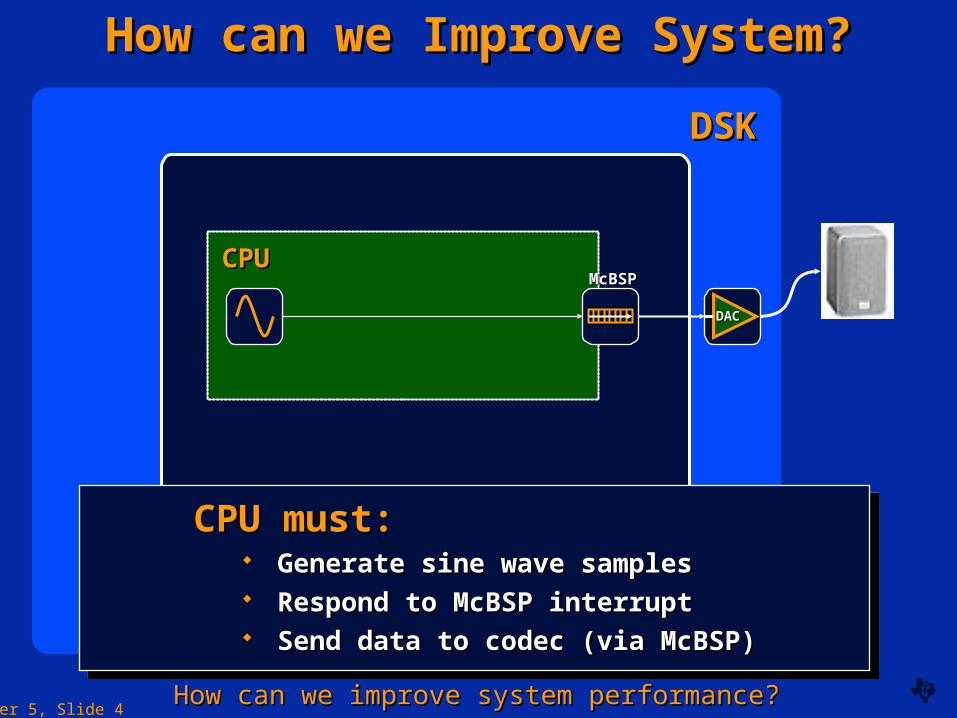
How can we Improve System?How can we Improve System?
McBSPMcBSP
CPU must:CPU must: Generate sine wave samplesGenerate sine wave samples Respond to McBSP interruptRespond to McBSP interrupt Send data to codec (via McBSP)Send data to codec (via McBSP)
CPU must:CPU must: Generate sine wave samplesGenerate sine wave samples Respond to McBSP interruptRespond to McBSP interrupt Send data to codec (via McBSP)Send data to codec (via McBSP)
How can we improve system performance?How can we improve system performance?
Chapter 5, Slide 5
DSKDSK
CPUCPU
DACDAC
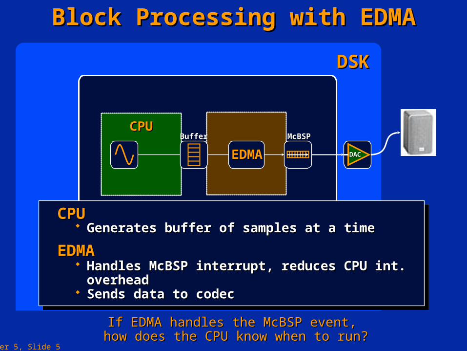
Block Processing with EDMABlock Processing with EDMA
McBSPMcBSPBufferBuffer
EDMAEDMA
CPUCPU Generates buffer of samples at a timeGenerates buffer of samples at a time
EDMAEDMA Handles McBSP interrupt, reduces CPU int. overheadHandles McBSP interrupt, reduces CPU int. overhead Sends data to codecSends data to codec
CPUCPU Generates buffer of samples at a timeGenerates buffer of samples at a time
EDMAEDMA Handles McBSP interrupt, reduces CPU int. overheadHandles McBSP interrupt, reduces CPU int. overhead Sends data to codecSends data to codec
If EDMA handles the McBSP event, If EDMA handles the McBSP event, how does the CPU know when to run?how does the CPU know when to run?
Chapter 5, Slide 6
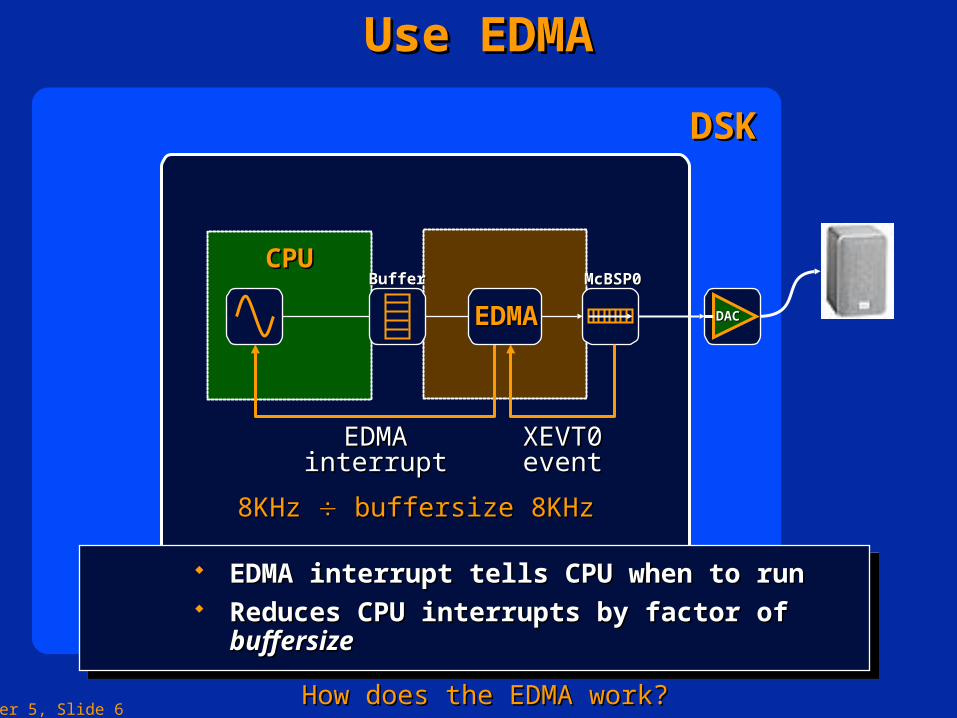
Use EDMAUse EDMA
DSKDSK
CPUCPU
DACDAC
McBSP0McBSP0BufferBuffer
XEVT0XEVT0eventevent
8KHz8KHz
EDMAEDMAinterruptinterrupt
8KHz 8KHz buffersize buffersize
EDMAEDMA
EDMA interrupt tells CPU when to runEDMA interrupt tells CPU when to run Reduces CPU interrupts by factor of Reduces CPU interrupts by factor of buffersizebuffersize
EDMA interrupt tells CPU when to runEDMA interrupt tells CPU when to run Reduces CPU interrupts by factor of Reduces CPU interrupts by factor of buffersizebuffersize
How does the EDMA work?How does the EDMA work?
Chapter 5, Slide 7
Introduction to the EDMAIntroduction to the EDMA
The ‘C6416 on-chip EDMA controller allows The ‘C6416 on-chip EDMA controller allows data transfers between the level two (L2) data transfers between the level two (L2) cache memory controller and the device cache memory controller and the device peripherals.peripherals.
These transfers include:These transfers include: Cache servicing.Cache servicing. Non-cacheable memory accesses.Non-cacheable memory accesses. User programmed data transfers.User programmed data transfers. Host accesses.Host accesses.
Chapter 5, Slide 8
EDMA InterfaceEDMA Interface The C621x/C671x/C641x Block diagram.The C621x/C671x/C641x Block diagram.
The EDMA allows data transfer to/from any addressable memory spaces.The EDMA allows data transfer to/from any addressable memory spaces.
Chapter 5, Slide 9
EDMA FunctionalityEDMA Functionality
The data transfer is performed with zero The data transfer is performed with zero overhead.overhead.
It is transparent to the CPU which means that It is transparent to the CPU which means that the EDMA and CPU operations can be the EDMA and CPU operations can be independent.independent.
However, if the EDMA and CPU both try to However, if the EDMA and CPU both try to access the same memory location arbitration access the same memory location arbitration will be performed by the program memory will be performed by the program memory controller.controller.
Chapter 5, Slide 10
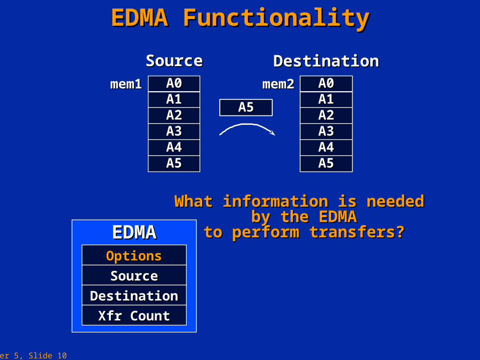
EDMA FunctionalityEDMA Functionality
What information is needed What information is needed by the EDMAby the EDMA
to perform transfers?to perform transfers?EDMAEDMA
SourceSource
DestinationDestination
Xfr CountXfr Count
OptionsOptions
mem1mem1 A0A0A1A1A2A2A3A3A4A4A5A5
mem2mem2 A0A0A1A1A2A2A3A3A4A4A5A5
A0A0A1A1A2A2A3A3A4A4A5A5
SourceSource DestinationDestination
Chapter 5, Slide 11
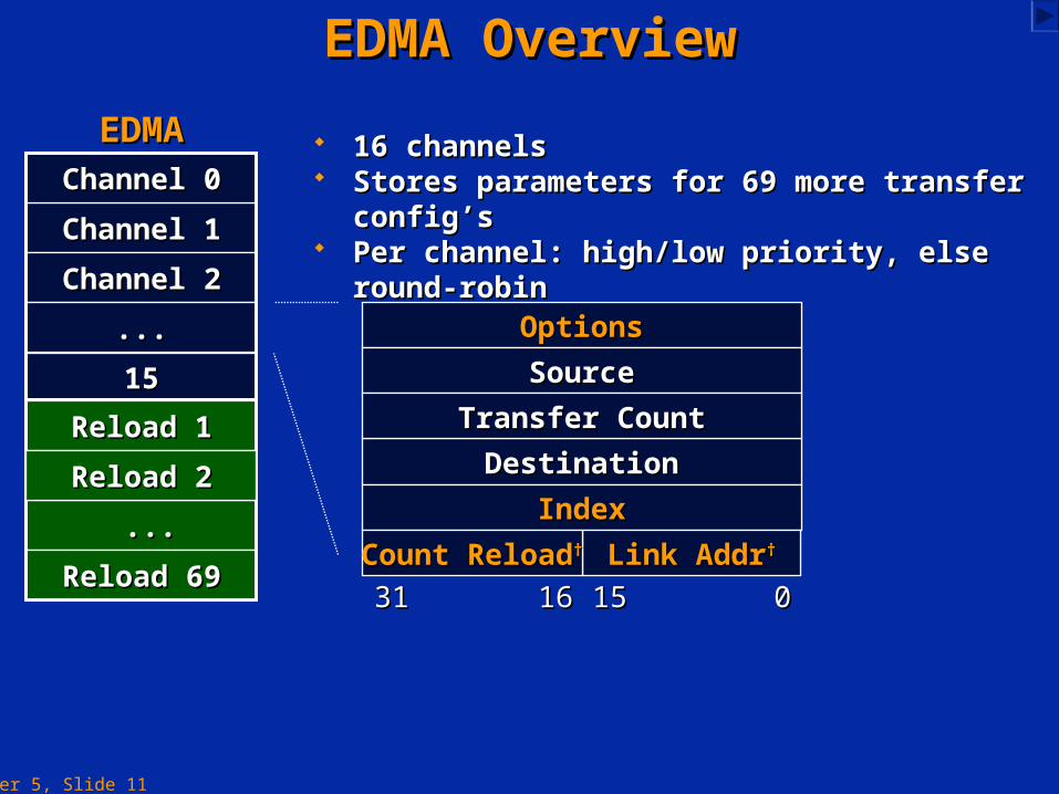
EDMA OverviewEDMA Overview
OptionsOptions
SourceSource
DestinationDestination
IndexIndex
Link AddrLink Addr††Count ReloadCount Reload††
3131 1616 1515 00
Transfer CountTransfer Count
16 channels16 channels Stores parameters for 69 more transfer config’sStores parameters for 69 more transfer config’s Per channel: high/low priority, else round-robinPer channel: high/low priority, else round-robin
1515
Channel 1Channel 1
Channel 2Channel 2
......
Reload 1Reload 1
......
Reload 69Reload 69
Channel 0Channel 0
EDMAEDMA
Reload 2Reload 2
Chapter 5, Slide 12
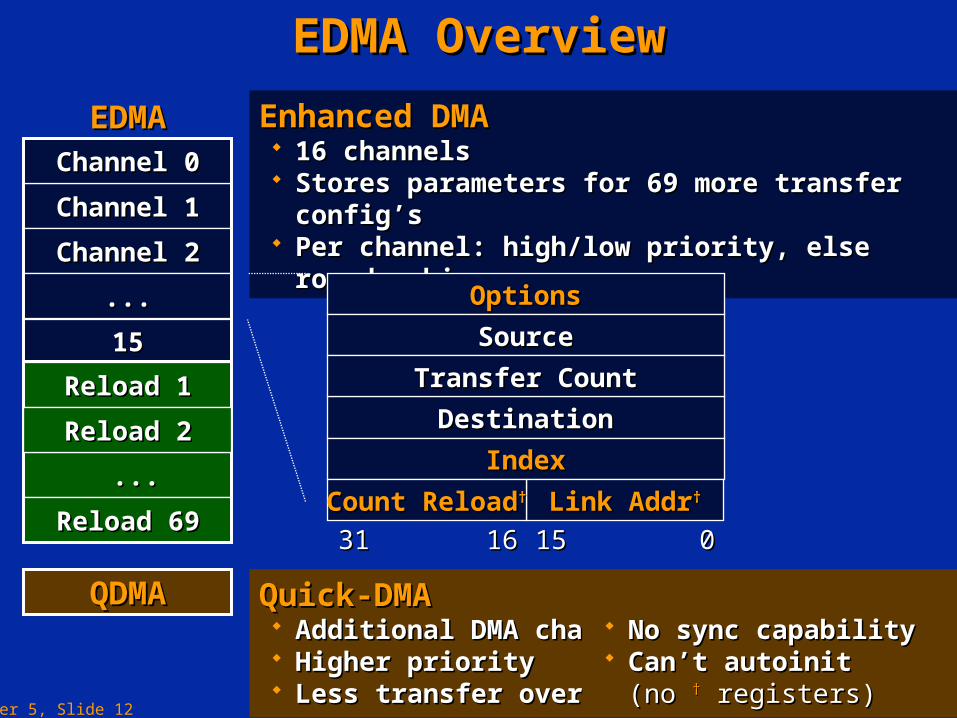
Enhanced DMAEnhanced DMA 16 channels16 channels Stores parameters for 69 more transfer config’sStores parameters for 69 more transfer config’s Per channel: high/low priority, else round-robinPer channel: high/low priority, else round-robin
EDMA OverviewEDMA Overview
OptionsOptions
SourceSource
DestinationDestination
IndexIndex
Link AddrLink Addr††Count ReloadCount Reload††
3131 1616 1515 00
Transfer CountTransfer Count1515
Channel 1Channel 1
Channel 2Channel 2
......
Reload 1Reload 1
......
Reload 69Reload 69
Channel 0Channel 0
EDMAEDMA
Reload 2Reload 2
QDMAQDMA Quick-DMAQuick-DMA Additional DMA channelAdditional DMA channel Higher priority Higher priority Less transfer overheadLess transfer overhead
No sync capabilityNo sync capability Can’t autoinit Can’t autoinit
(no (no †† registers) registers)
Chapter 5, Slide 13
EDMA FeaturesEDMA Features
The ‘C6416 on-chip EDMA controller has the The ‘C6416 on-chip EDMA controller has the following features:following features:
16 channels.16 channels. 1 auxiliary channel dedicated for the HPI (not 1 auxiliary channel dedicated for the HPI (not
accessible to the user).accessible to the user). 1 Quick DMA (QDMA).1 Quick DMA (QDMA).
Chapter 5, Slide 14
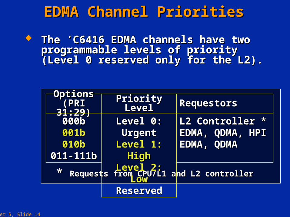
EDMA Channel PrioritiesEDMA Channel Priorities
The ‘C6416 EDMA channels have two The ‘C6416 EDMA channels have two programmable levels of priority (Level 0 programmable levels of priority (Level 0 reserved only for the L2).reserved only for the L2).
* * Requests from CPU/L1 and L2 controllerRequests from CPU/L1 and L2 controller
Options Options (PRI 31:29)(PRI 31:29) Priority LevelPriority Level RequestorsRequestors
000b000b001b001b010b010b
011-111b011-111b
Level 0: UrgentLevel 0: UrgentLevel 1: HighLevel 1: HighLevel 2: LowLevel 2: Low
ReservedReserved
L2 Controller *L2 Controller *EDMA, QDMA, HPIEDMA, QDMA, HPIEDMA, QDMAEDMA, QDMA

Chapter 5, Slide 15
EDMA PerformanceEDMA Performance
The ‘C6211/C6711 EDMA can perform The ‘C6211/C6711 EDMA can perform element transfers with element transfers with single-cyclesingle-cycle throughput throughput provided there is no conflict.provided there is no conflict.
The following conditions can limit the The following conditions can limit the performance:performance: EDMA stalls when there are multiple transfer EDMA stalls when there are multiple transfer
requests on the same priority level.requests on the same priority level. EDMA accesses to L2 SRAM with lower priority EDMA accesses to L2 SRAM with lower priority
than the CPU.than the CPU.
Chapter 5, Slide 16
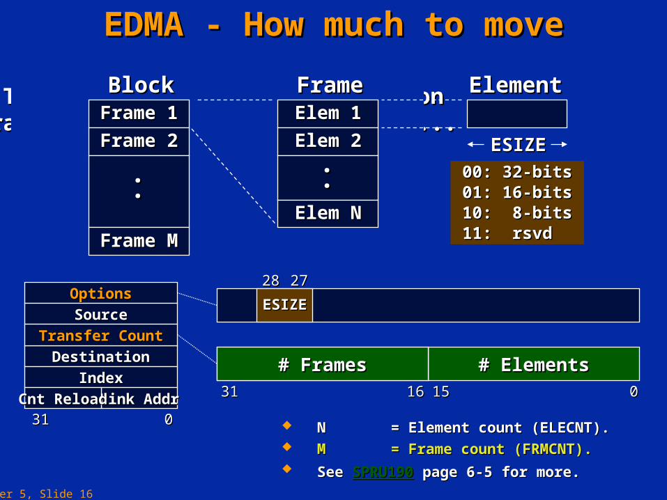
The smallest piece of informationThe smallest piece of informationtransferred by the EDMA is called... transferred by the EDMA is called...
EDMA - How much to moveEDMA - How much to move
ElementElement
ESIZEESIZE
00: 32-bits00: 32-bits01: 16-bits01: 16-bits10: 8-bits10: 8-bits11: rsvd11: rsvd
ESIZEESIZE
2828 2727
Elem 1Elem 1
Elem 2Elem 2
Elem NElem N
FrameFrame
..
..
Frame 1Frame 1
Frame 2Frame 2
Frame MFrame M
BlockBlock
..
..
# Elements# Elements
00151516163131
# Frames# Frames
OptionsOptions
SourceSource
DestinationDestination
IndexIndex
Link AddrLink AddrCnt ReloadCnt Reload
3131 00
Transfer CountTransfer Count
N N = Element count (ELECNT).= Element count (ELECNT). M M = Frame count (FRMCNT).= Frame count (FRMCNT). See See SPRU190SPRU190 page 6-5 for more.page 6-5 for more.
Chapter 5, Slide 17
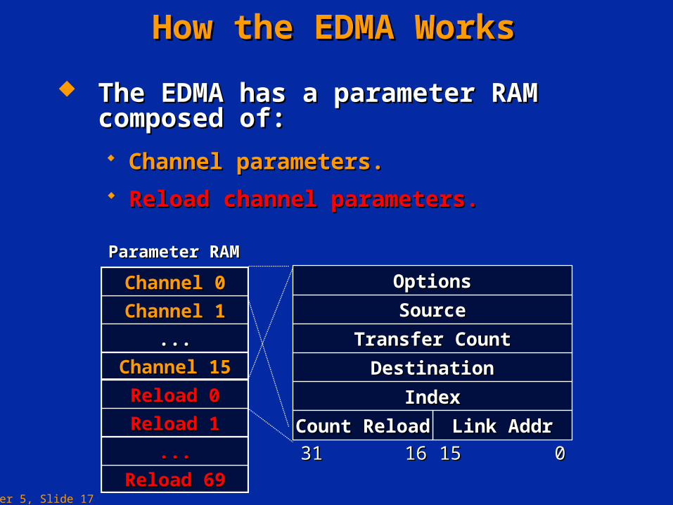
How the EDMA WorksHow the EDMA Works
Reload channel parameters.Reload channel parameters.
OptionsOptions
SourceSource
DestinationDestination
IndexIndex
Link AddrLink AddrCount ReloadCount Reload
3131 1616 1515 00
Transfer CountTransfer Count
Channel 15Channel 15
Channel 1Channel 1
......
Channel 0Channel 0
Reload 69Reload 69
Reload 1Reload 1
......
Reload 0Reload 0
The EDMA has a parameter RAM composed The EDMA has a parameter RAM composed of:of:
Parameter RAMParameter RAM
Channel parameters.Channel parameters.
Chapter 5, Slide 18
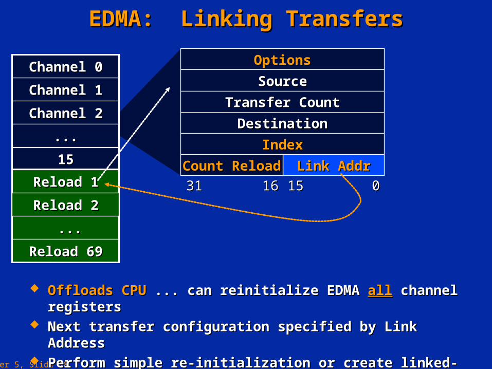
EDMA: Linking TransfersEDMA: Linking Transfers
Offloads CPUOffloads CPU ... can reinitialize EDMA ... can reinitialize EDMA allall channel registers channel registers Next transfer configuration specified by Link Address Next transfer configuration specified by Link Address Perform simple re-initialization or create linked-list of eventsPerform simple re-initialization or create linked-list of events Useful for Useful for ping-pong buffersping-pong buffers, data sorting, circular buffers, etc., data sorting, circular buffers, etc.
OptionsOptions
SourceSource
DestinationDestination
IndexIndex
Link AddrLink AddrCount ReloadCount Reload
3131 1616 1515 00
Transfer CountTransfer Count
1515
Channel 1Channel 1
Channel 2Channel 2
......
Reload 1Reload 1
......
Reload 69Reload 69
Channel 0Channel 0
Reload 2Reload 2
Chapter 5, Slide 19
How the EDMA WorksHow the EDMA Works
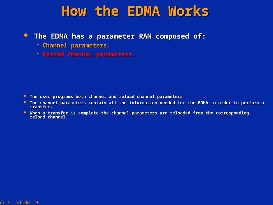
The EDMA has a parameter RAM composed of:The EDMA has a parameter RAM composed of: Channel parameters.Channel parameters. Reload channel parameters.Reload channel parameters.
The user programs both channel and reload channel parameters.The user programs both channel and reload channel parameters. The channel parameters contain all the information needed for the EDMA in order to perform a transfer.The channel parameters contain all the information needed for the EDMA in order to perform a transfer. When a transfer is complete the channel parameters are reloaded from the corresponding reload channel.When a transfer is complete the channel parameters are reloaded from the corresponding reload channel.
Chapter 5, Slide 20
EDMA ParametersEDMA Parameters
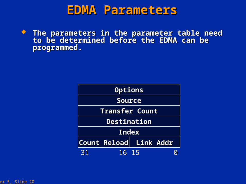
The parameters in the parameter table need to be The parameters in the parameter table need to be determined before the EDMA can be programmed.determined before the EDMA can be programmed.
OptionsOptions
SourceSource
DestinationDestination
IndexIndex
Link AddrLink AddrCount ReloadCount Reload
3131 1616 1515 00
Transfer CountTransfer Count
Chapter 5, Slide 21
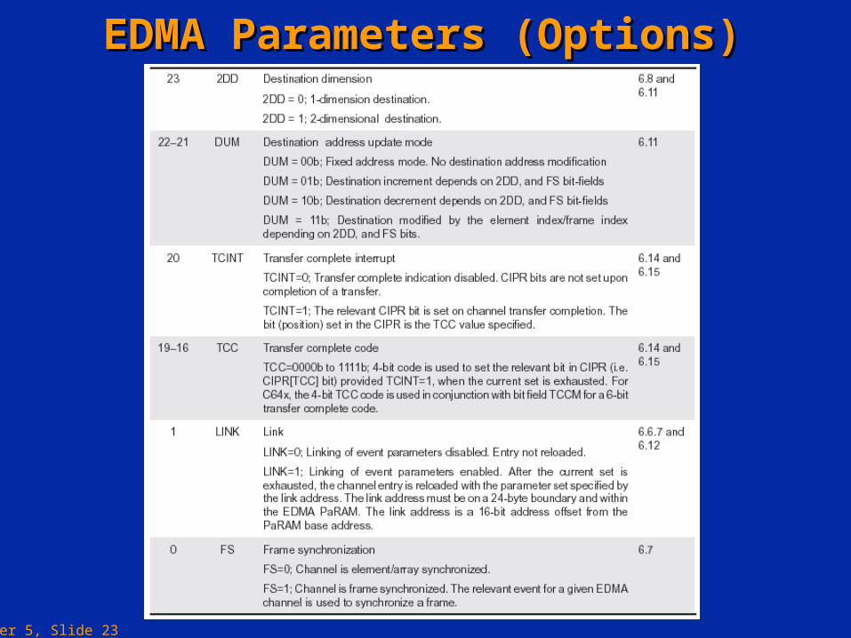
EDMA Parameters (Options)EDMA Parameters (Options)
EDMA Channel Options RegisterEDMA Channel Options Register
ESIZEESIZE 2DS2DS TCCTCCTCINTTCINTSUMSUMPRIPRI31 2931 29
2DD2DD DUMDUM LINKLINK FSFS28 2728 27 2626 25 2425 24 2323 22 2122 21 2020 19 1619 16 11 00
RSVDRSVD15 215 2
Bit FieldBit Field
31:2931:29
28:2728:27
2626
25:2425:24
2323
22:2122:21
2020
19:1619:16
11
00
LabelLabel
PRIPRI
ESIZEESIZE
2DS2DS
SUMSUM
2DD2DD
DUMDUM
TCINTTCINT
TCCTCC
LINKLINK
FSFS
DescriptionDescription
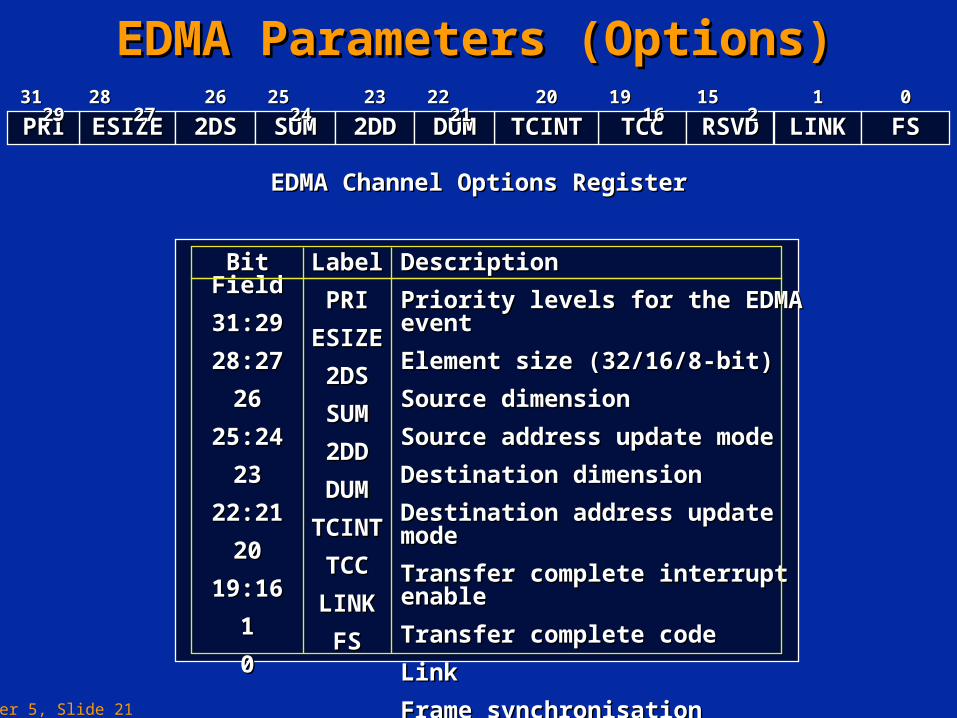
Priority levels for the EDMA eventPriority levels for the EDMA event
Element size (32/16/8-bit)Element size (32/16/8-bit)
Source dimensionSource dimension
Source address update modeSource address update mode
Destination dimensionDestination dimension
Destination address update modeDestination address update mode
Transfer complete interrupt enableTransfer complete interrupt enable
Transfer complete codeTransfer complete code
LinkLink
Frame synchronisationFrame synchronisation
Chapter 5, Slide 22
EDMA Parameters (Options)EDMA Parameters (Options)
Chapter 5, Slide 23
EDMA Parameters (Options)EDMA Parameters (Options)
Chapter 5, Slide 24
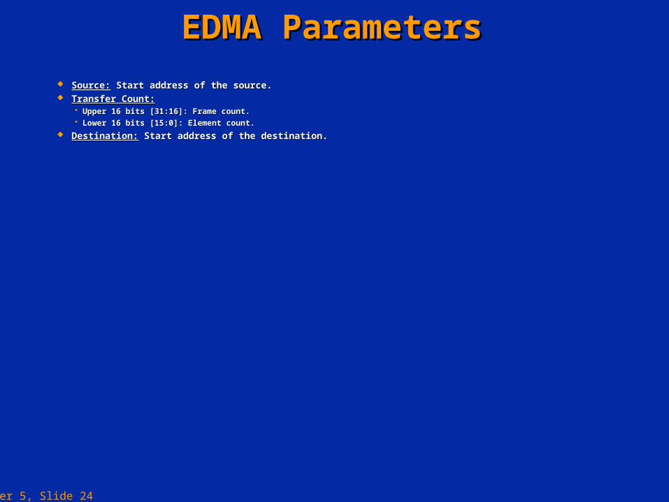
EDMA ParametersEDMA Parameters
Source:Source: Start address of the source. Start address of the source. Transfer Count:Transfer Count:
Upper 16 bits [31:16]: Frame count.Upper 16 bits [31:16]: Frame count. Lower 16 bits [15:0]: Element count.Lower 16 bits [15:0]: Element count.
Destination:Destination: Start address of the destination. Start address of the destination.
Chapter 5, Slide 25
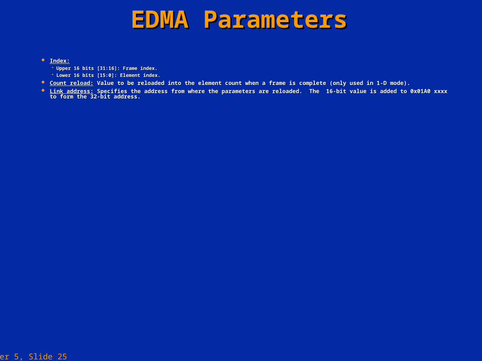
EDMA ParametersEDMA Parameters
Index:Index: Upper 16 bits [31:16]: Frame index.Upper 16 bits [31:16]: Frame index. Lower 16 bits [15:0]: Element index.Lower 16 bits [15:0]: Element index.
Count reload:Count reload: Value to be reloaded into the element count when a frame is complete (only used in 1-D mode). Value to be reloaded into the element count when a frame is complete (only used in 1-D mode). Link address:Link address: Specifies the address from where the parameters are reloaded. The 16-bit value is added to 0x01A0 xxxx to form the 32-bit address. Specifies the address from where the parameters are reloaded. The 16-bit value is added to 0x01A0 xxxx to form the 32-bit address.

Chapter 5, Slide 26
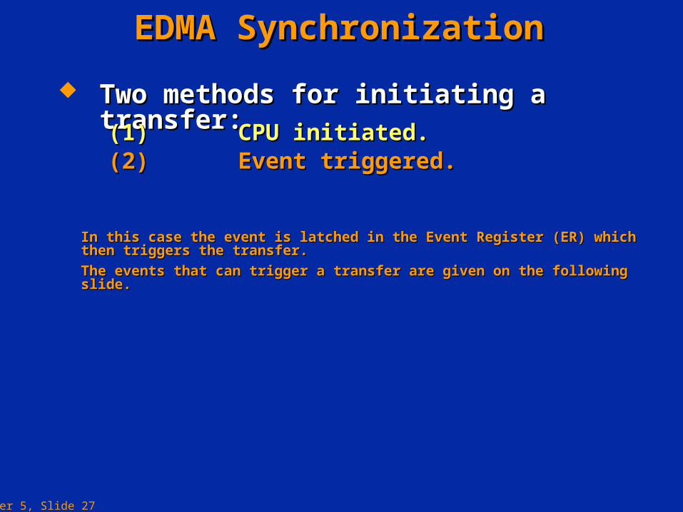
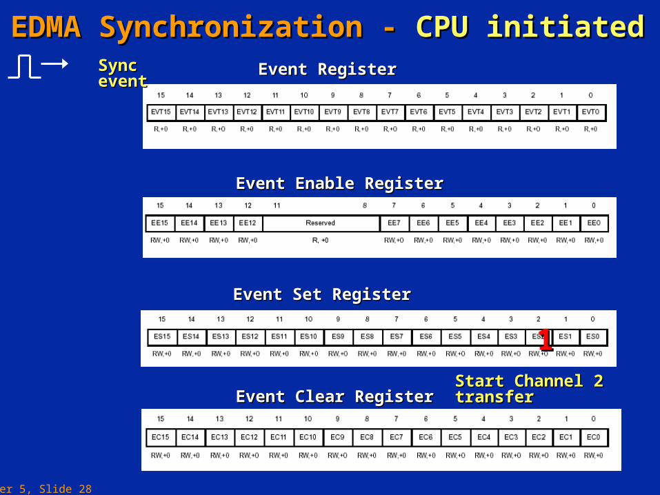
EDMA SynchronizationEDMA Synchronization
Two methods for initiating a transfer:Two methods for initiating a transfer:
This is known as unsynchronized EDMA. With This is known as unsynchronized EDMA. With this method the CPU writes to the Event Register this method the CPU writes to the Event Register (ER) through the Event Set Register (ESR) in (ER) through the Event Set Register (ESR) in order to start the EDMA transfer (this can be order to start the EDMA transfer (this can be used to simulate an event).used to simulate an event).
(1)(1) CPU initiated.CPU initiated.
Chapter 5, Slide 27
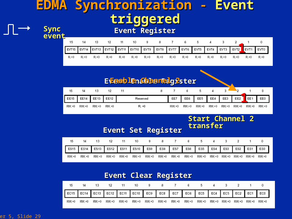
In this case the event is latched in the Event Register (ER) which then In this case the event is latched in the Event Register (ER) which then triggers the transfer.triggers the transfer.
The events that can trigger a transfer are given on the following slide.The events that can trigger a transfer are given on the following slide.
EDMA SynchronizationEDMA Synchronization
Two methods for initiating a transfer:Two methods for initiating a transfer:
(2)(2) Event triggered.Event triggered.(1)(1) CPU initiated.CPU initiated.
Chapter 5, Slide 28
EDMA Synchronization - EDMA Synchronization - CPU initiatedCPU initiated
Event Enable RegisterEvent Enable Register
Event Set RegisterEvent Set Register
Event Clear RegisterEvent Clear Register
Event RegisterEvent RegisterSync eventSync event
11Start Channel 2 transferStart Channel 2 transfer
Chapter 5, Slide 29
EDMA Synchronization - EDMA Synchronization - Event triggeredEvent triggered
Event Enable RegisterEvent Enable Register
Event Set RegisterEvent Set Register
Event Clear RegisterEvent Clear Register
Event RegisterEvent RegisterSync eventSync event
11
Enable Channel 2Enable Channel 2
11
Start Channel 2 transferStart Channel 2 transfer
Chapter 5, Slide 30
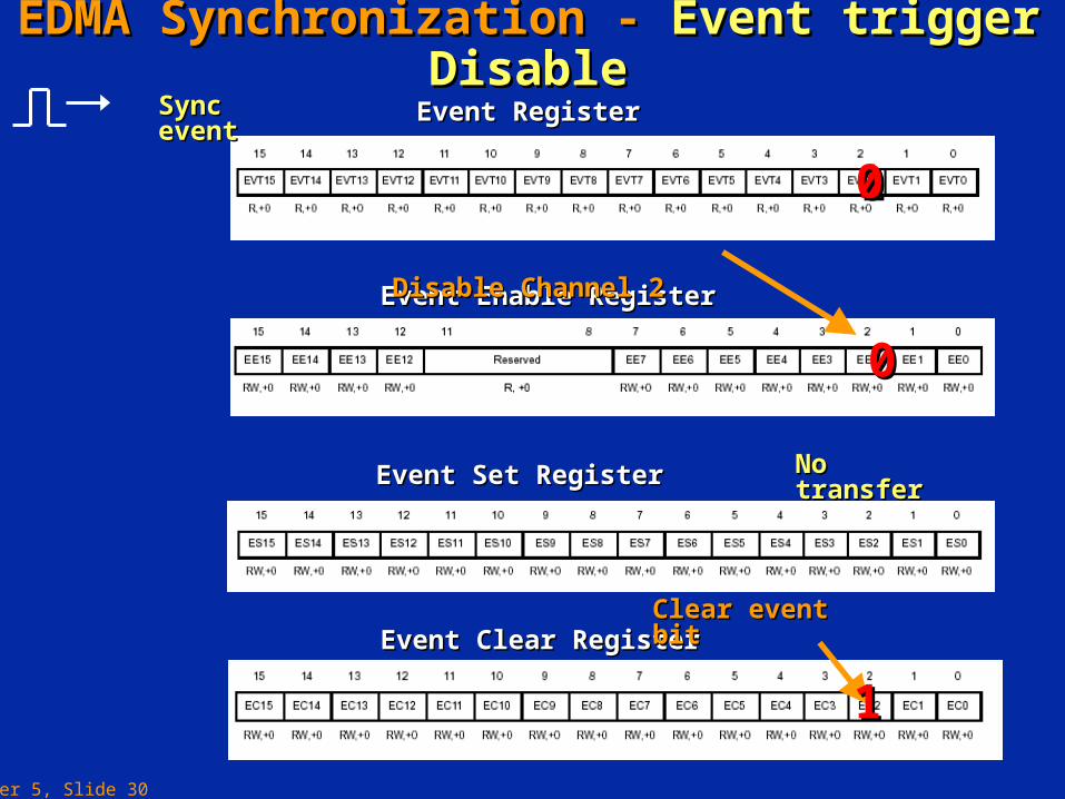
EDMA Synchronization - EDMA Synchronization - Event trigger DisableEvent trigger Disable
Event Enable RegisterEvent Enable Register
Event Set RegisterEvent Set Register
Event Clear RegisterEvent Clear Register
Event RegisterEvent RegisterSync eventSync event
1100
Disable Channel 2Disable Channel 2
00
No transferNo transfer
Clear event bitClear event bit
11
Chapter 5, Slide 31
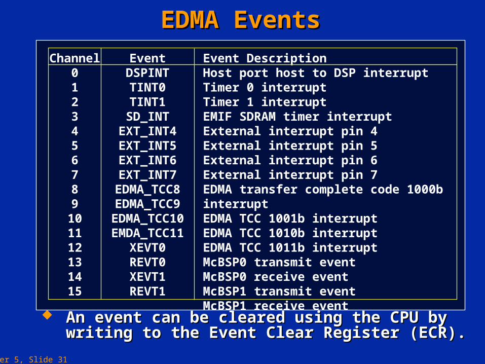
EDMA EventsEDMA Events
An event can be cleared using the CPU by writing An event can be cleared using the CPU by writing to the Event Clear Register (ECR).to the Event Clear Register (ECR).
Channel0123456789
101112131415
EventDSPINTTINT0TINT1
SD_INTEXT_INT4EXT_INT5EXT_INT6EXT_INT7
EDMA_TCC8EDMA_TCC9EDMA_TCC10EMDA_TCC11
XEVT0REVT0XEVT1REVT1
Event DescriptionHost port host to DSP interruptTimer 0 interruptTimer 1 interruptEMIF SDRAM timer interruptExternal interrupt pin 4External interrupt pin 5External interrupt pin 6External interrupt pin 7EDMA transfer complete code 1000b interruptEDMA TCC 1001b interruptEDMA TCC 1010b interruptEDMA TCC 1011b interruptMcBSP0 transmit eventMcBSP0 receive eventMcBSP1 transmit eventMcBSP1 receive event
Chapter 5, Slide 32
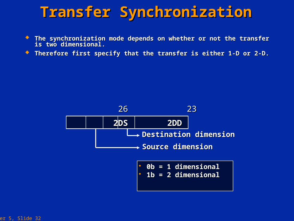
Transfer SynchronizationTransfer Synchronization
The synchronization mode depends on whether or not the transfer is The synchronization mode depends on whether or not the transfer is two dimensional.two dimensional.
Therefore first specify that the transfer is either 1-D or 2-D.Therefore first specify that the transfer is either 1-D or 2-D.
0b = 1 dimensional0b = 1 dimensional 1b = 2 dimensional1b = 2 dimensional
2DS 2DD Options Register2DS 2DD Options Register
26 2326 23
Destination dimensionDestination dimension
Source dimensionSource dimension

Chapter 5, Slide 33
1-D Synchronisation1-D Synchronisation
There are two modes of synchronisation in the 1-D transfer mode.There are two modes of synchronisation in the 1-D transfer mode. These are:These are:
Element synchronized: each event causes one element to be transferred.Element synchronized: each event causes one element to be transferred. Frame synchronized: each event causes a whole frame to be transferred.Frame synchronized: each event causes a whole frame to be transferred.
The FS bit is used to specify the synchronization mode.The FS bit is used to specify the synchronization mode.
Chapter 5, Slide 34
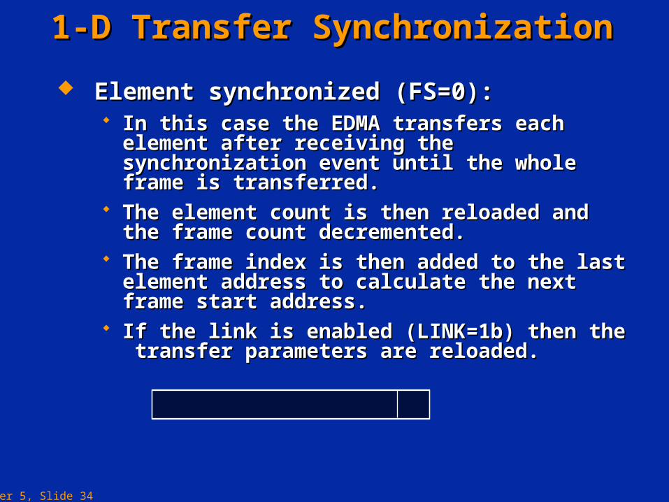
1-D Transfer Synchronization1-D Transfer Synchronization
Element synchronized (FS=0):Element synchronized (FS=0): In this case the EDMA transfers each element after In this case the EDMA transfers each element after
receiving the synchronization event until the whole receiving the synchronization event until the whole frame is transferred.frame is transferred.
The element count is then reloaded and the frame The element count is then reloaded and the frame count decremented.count decremented.
The frame index is then added to the last element The frame index is then added to the last element address to calculate the next frame start address.address to calculate the next frame start address.
If the link is enabled (LINK=1b) then the transfer If the link is enabled (LINK=1b) then the transfer parameters are reloaded.parameters are reloaded.
FS Options RegisterFS Options Register
00
Chapter 5, Slide 35
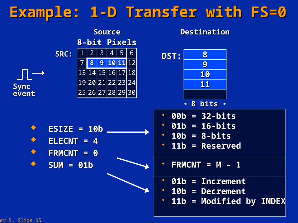
Example: 1-D Transfer with FS=0Example: 1-D Transfer with FS=0
ESIZE = 10bESIZE = 10b ELECNT = 4ELECNT = 4 FRMCNT = 0FRMCNT = 0 SUM = 01bSUM = 01b
DST:DST:
8 bits8 bits
889910101111
8-bit Pixels8-bit Pixels11 22 33 44 55 66
77 1212
1313 1414 1515 1616 1717 1818
1919 2020 2121 2222 2323 2424
2525 2626 2727 2828 2929 3030
88 99 1010 1111889910101111
88 99 1010 1111SRC:SRC:
SourceSource DestinationDestination
Sync eventSync event
00b = 32-bits00b = 32-bits 01b = 16-bits01b = 16-bits 10b = 8-bits10b = 8-bits 11b = Reserved11b = Reserved
00b = Fixed00b = Fixed 01b = Increment01b = Increment 10b = Decrement10b = Decrement 11b = Modified by INDEX11b = Modified by INDEX
FRMCNT = M - 1FRMCNT = M - 1
Chapter 5, Slide 36
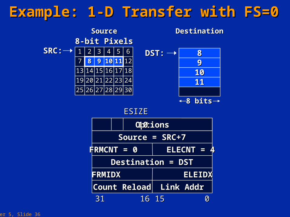
Example: 1-D Transfer with FS=0Example: 1-D Transfer with FS=0
DST:DST:
8 bits8 bits
889910101111
8-bit Pixels8-bit Pixels11 22 33 44 55 66
77 1212
1313 1414 1515 1616 1717 1818
1919 2020 2121 2222 2323 2424
2525 2626 2727 2828 2929 3030
88 99 1010 1111889910101111
88 99 1010 1111
Source = SRC+7Source = SRC+7
Destination = DSTDestination = DST
FRMIDX ELEIDXFRMIDX ELEIDX
Link AddrLink AddrCount ReloadCount Reload
3131 1616 1515 00
FRMCNT = 0 ELECNT = 4FRMCNT = 0 ELECNT = 4
ESIZEESIZE
OptionsOptions 1010
SRC:SRC:
SourceSource DestinationDestination

Chapter 5, Slide 37
DST:DST:
8 bits8 bits
661010141418182222
Example: 1-D Transfer with FS=0Example: 1-D Transfer with FS=0
ESIZE = 10b (8-bits)ESIZE = 10b (8-bits) ELECNT = 5, FRMCNT = 0ELECNT = 5, FRMCNT = 0 SUM = 11bSUM = 11b ELEIDX = 4ELEIDX = 4
8-bit Pixels8-bit Pixels11 22 33 44
55
99 1010 1111 1212
1313 1414 1515 1616
1717 1818 1919 2020
66 77 88
2121 2222 2323 2424
2525 2626 2727 2828
66
1010
1414
1818
2222
661010141418182222
SourceSource DestinationDestination
SRC:SRC:
In this mode:In this mode:Next frame addr = Next frame addr = LastLast element addr + FRMIDX element addr + FRMIDX
Sync eventSync event
Chapter 5, Slide 38
1-D Transfer Synchronisation1-D Transfer Synchronisation
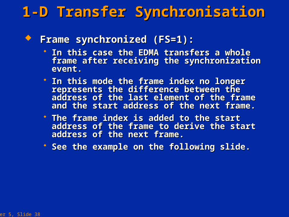
Frame synchronized (FS=1):Frame synchronized (FS=1): In this case the EDMA transfers a whole frame In this case the EDMA transfers a whole frame
after receiving the synchronization event.after receiving the synchronization event. In this mode the frame index no longer represents In this mode the frame index no longer represents
the difference between the address of the last the difference between the address of the last element of the frame and the start address of the element of the frame and the start address of the next frame.next frame.
The frame index is added to the start address of the The frame index is added to the start address of the frame to derive the start address of the next frame.frame to derive the start address of the next frame.
See the example on the following slide.See the example on the following slide.
Chapter 5, Slide 39
16 bits16 bits
88101012121616
3636......
404042424444......
16-bit Data16-bit Data11 22 33 44 55 66 77
1212 1313 1414
1515 1616 1717 1818 1919 2020 2121
2222 2323 2424 2525 2626 2727 2828
88 99 1010 1111
2929 3030 3131 3232 3333 3434 3535
3636 3737 3838 3939 4040 4141 4242
4343 4444 4545 4646 4747 4848 4949
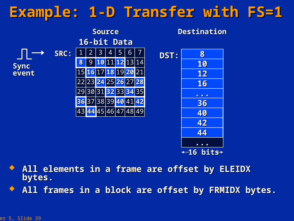
Example: 1-D Transfer with FS=1Example: 1-D Transfer with FS=1
All elements in a frame are offset by ELEIDX bytes.All elements in a frame are offset by ELEIDX bytes. All frames in a block are offset by FRMIDX bytes.All frames in a block are offset by FRMIDX bytes.
DST:DST: 8810101212
121288 1010SRC:SRC:
SourceSource DestinationDestination
20201616 1818
28282424 2626
3232 3434
3636
1616......3636404042424444
4040 4242
4444
Sync eventSync event
Chapter 5, Slide 40
16 bits16 bits
88101012121616
3636......
404042424444
16-bit Data16-bit Data11 22 33 44 55 66 77
1212 1313 1414
1515 1616 1717 1818 1919 2020 2121
2222 2323 2424 2525 2626 2727 2828
88 99 1010 1111
2929 3030 3131 3232 3333 3434 3535
3636 3737 3838 3939 4040 4141 4242
4343 4444 4545 4646 4747 4848 4949
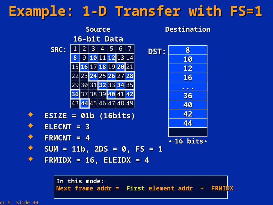
Example: 1-D Transfer with FS=1Example: 1-D Transfer with FS=1
ESIZE = 01b (16bits)ESIZE = 01b (16bits) ELECNT = 3ELECNT = 3 FRMCNT = 4FRMCNT = 4 SUM = 11b, 2DS = 0, FS = 1SUM = 11b, 2DS = 0, FS = 1 FRMIDX = 16, ELEIDX = 4FRMIDX = 16, ELEIDX = 4
DST:DST: 8810101212
121288 1010SRC:SRC:
SourceSource DestinationDestination
20201616 1818
28282424 2626
3636
3232 34341616......3636404042424444
4040 4242
4444
In this mode:In this mode:Next frame addr = Next frame addr = FirstFirst element addr + FRMIDX element addr + FRMIDX
Chapter 5, Slide 41
DST:DST:
8 bits8 bits
8-bit Pixels8-bit Pixels11 22 33 44 55 66
77 1212
1313 1414 1515 1616 1717 1818
1919 2020 2121 2222 2323 2424
2525 2626 2727 2828 2929 3030
88 99 1010 1111SRC:SRC:
SourceSource DestinationDestination
22441414161626262828
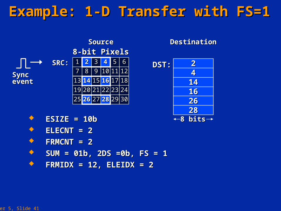
Example: 1-D Transfer with FS=1Example: 1-D Transfer with FS=1
22 44
1414 1616
2626 2828
ESIZE = 10bESIZE = 10b ELECNT = 2ELECNT = 2 FRMCNT = 2FRMCNT = 2 SUM = 01b, 2DS =0b, FS = 1SUM = 01b, 2DS =0b, FS = 1 FRMIDX = 12, ELEIDX = 2FRMIDX = 12, ELEIDX = 2
22441414161626262828
Sync eventSync event
Chapter 5, Slide 42
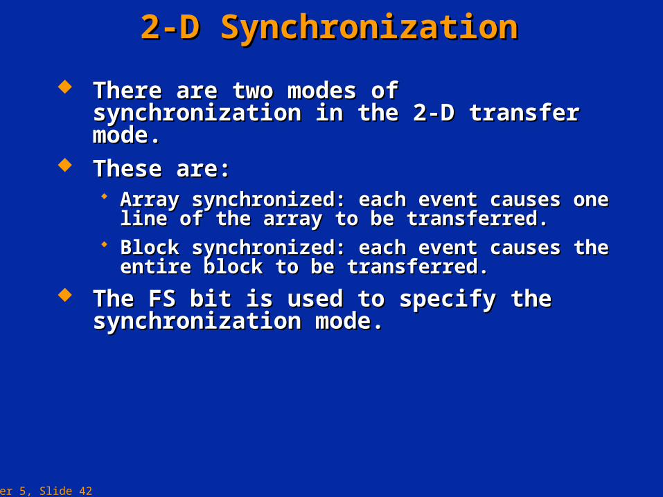
2-D Synchronization2-D Synchronization
There are two modes of synchronization in the There are two modes of synchronization in the 2-D transfer mode.2-D transfer mode.
These are:These are: Array synchronized: each event causes one line of Array synchronized: each event causes one line of
the array to be transferred.the array to be transferred. Block synchronized: each event causes the entire Block synchronized: each event causes the entire
block to be transferred.block to be transferred.
The FS bit is used to specify the The FS bit is used to specify the synchronization mode.synchronization mode.
Chapter 5, Slide 43
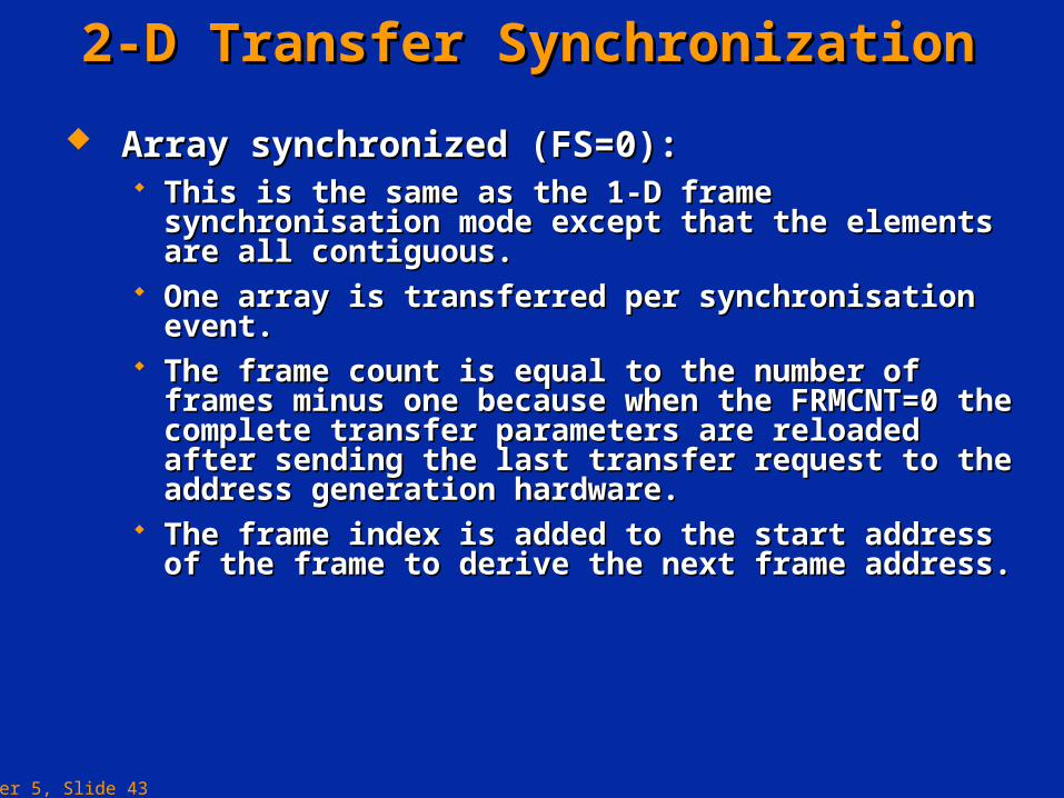
2-D Transfer Synchronization2-D Transfer Synchronization
Array synchronized (FS=0):Array synchronized (FS=0): This is the same as the 1-D frame synchronisation mode This is the same as the 1-D frame synchronisation mode
except that the elements are all contiguous.except that the elements are all contiguous. One array is transferred per synchronisation event.One array is transferred per synchronisation event. The frame count is equal to the number of frames The frame count is equal to the number of frames
minus one because when the FRMCNT=0 the complete minus one because when the FRMCNT=0 the complete transfer parameters are reloaded after sending the last transfer parameters are reloaded after sending the last transfer request to the address generation hardware.transfer request to the address generation hardware.
The frame index is added to the start address of the The frame index is added to the start address of the frame to derive the next frame address.frame to derive the next frame address.
Chapter 5, Slide 44
16-bit Data16-bit Data11 22 33 44 55 66 77
1212 1313 1414
1515 1616 1717 1818 1919 2020 2121
2222 2323 2424 2525 2626 2727 2828
88 99 1010 1111
2929 3030 3131 3232 3333 3434 3535
3636 3737 3838 3939 4040 4141 4242
4343 4444 4545 4646 4747 4848 4949
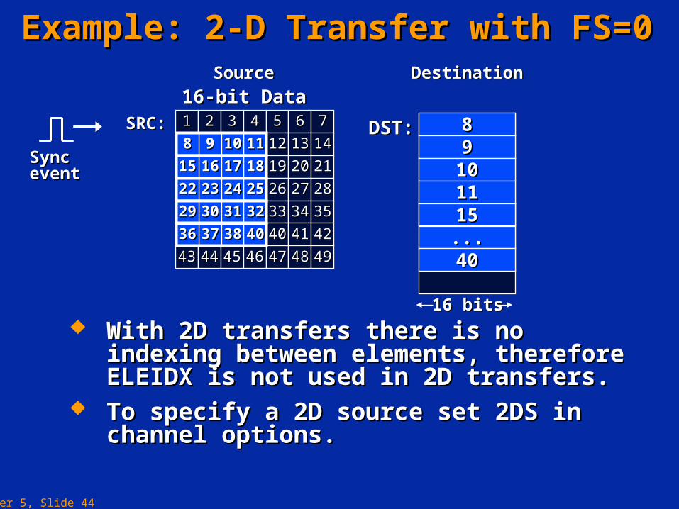
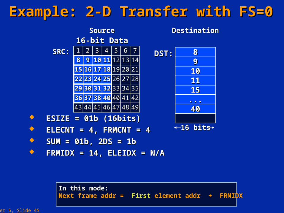
Example: 2-D Transfer with FS=0Example: 2-D Transfer with FS=0
With 2D transfers there is no indexing With 2D transfers there is no indexing between elements, therefore ELEIDX is not between elements, therefore ELEIDX is not used in 2D transfers.used in 2D transfers.
To specify a 2D source set 2DS in channel To specify a 2D source set 2DS in channel options.options.
16 bits16 bits
889910101111
......1515
4040
DST:DST:99 111188 1010
SRC:SRC:
SourceSource DestinationDestination
889910101111
1616 18181515 1717
2323 25252222 2424
3030 32322929 3131
3737 40403636 38381515......4040
Sync eventSync event
Chapter 5, Slide 45
16-bit Data16-bit Data11 22 33 44 55 66 77
1212 1313 1414
1515 1616 1717 1818 1919 2020 2121
2222 2323 2424 2525 2626 2727 2828
88 99 1010 1111
2929 3030 3131 3232 3333 3434 3535
3636 3737 3838 3939 4040 4141 4242
4343 4444 4545 4646 4747 4848 4949
Example: 2-D Transfer with FS=0Example: 2-D Transfer with FS=0
16 bits16 bits
889910101111
......1515
4040
DST:DST:99 111188 1010
SRC:SRC:
SourceSource DestinationDestination
889910101111
1616 18181515 1717
2323 25252222 2424
3030 32322929 3131
3737 40403636 38381515......4040
ESIZE = 01b (16bits)ESIZE = 01b (16bits) ELECNT = 4, FRMCNT = 4ELECNT = 4, FRMCNT = 4 SUM = 01b, 2DS = 1bSUM = 01b, 2DS = 1b FRMIDX = 14, ELEIDX = N/AFRMIDX = 14, ELEIDX = N/A
In this mode:In this mode:Next frame addr = Next frame addr = FirstFirst element addr + FRMIDX element addr + FRMIDX
Chapter 5, Slide 46
2-D Transfer Synchronization2-D Transfer Synchronization
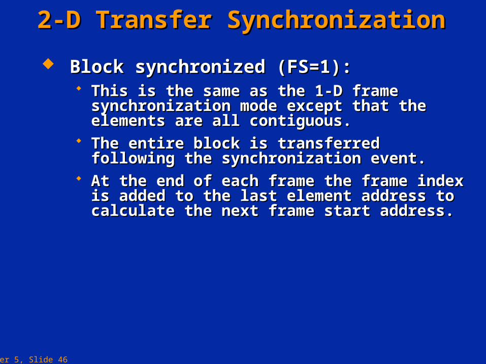
Block synchronized (FS=1):Block synchronized (FS=1): This is the same as the 1-D frame synchronization This is the same as the 1-D frame synchronization
mode except that the elements are all contiguous.mode except that the elements are all contiguous. The entire block is transferred following the The entire block is transferred following the
synchronization event.synchronization event. At the end of each frame the frame index is added to At the end of each frame the frame index is added to
the last element address to calculate the next frame the last element address to calculate the next frame start address.start address.
Chapter 5, Slide 47
Example: 2-D Transfer with FS=1Example: 2-D Transfer with FS=1
16-bit Data16-bit Data11 22 33 44 55 66 77
1212 1313 1414
1515 1616 1717 1818 1919 2020 2121
2222 2323 2424 2525 2626 2727 2828
88 99 1010 1111
2929 3030 3131 3232 3333 3434 3535
3636 3737 3838 3939 4040 4141 4242
4343 4444 4545 4646 4747 4848 4949
16 bits16 bits
889910101111
......1515
4040
DST:DST:99 111188 1010
SRC:SRC: 889910101111
1616 18181515 1717
2323 25252222 2424
3030 32322929 3131
3737 40403636 38381515......4040
SourceSource DestinationDestination
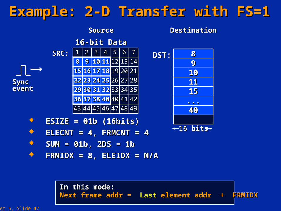
ESIZE = 01b (16bits)ESIZE = 01b (16bits) ELECNT = 4, FRMCNT = 4ELECNT = 4, FRMCNT = 4 SUM = 01b, 2DS = 1bSUM = 01b, 2DS = 1b FRMIDX = 8, ELEIDX = N/AFRMIDX = 8, ELEIDX = N/A
In this mode:In this mode:Next frame addr = Next frame addr = LastLast element addr + FRMIDX element addr + FRMIDX
Sync eventSync event
Chapter 5, Slide 48
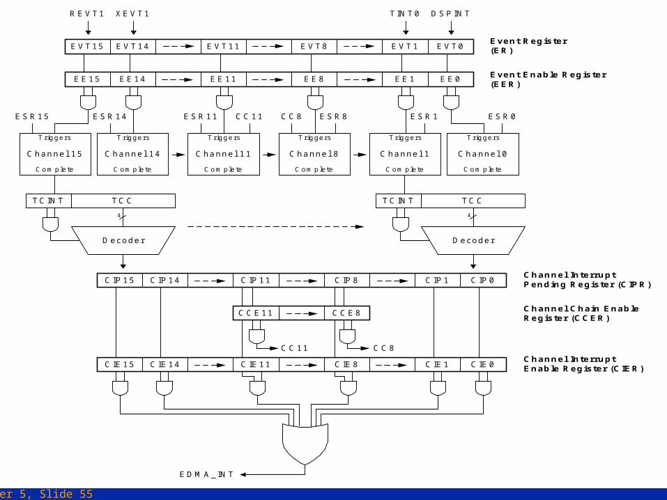
EDMA Interrupt GenerationEDMA Interrupt Generation
The EDMA controller is responsible for generating transfer completion interrupts to the CPU.The EDMA controller is responsible for generating transfer completion interrupts to the CPU. The EDMA generates a single interrupt (EDMA_INT) to the CPU on behalf of all 16 channels.The EDMA generates a single interrupt (EDMA_INT) to the CPU on behalf of all 16 channels. The programmer has to read the CIPR register to determine which channel caused the interrupt or The programmer has to read the CIPR register to determine which channel caused the interrupt or
which interrupts are pending while the ISR is being serviced.which interrupts are pending while the ISR is being serviced.
Chapter 5, Slide 49
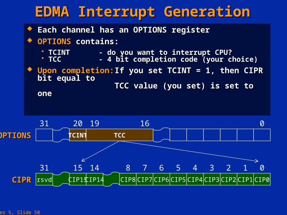
EDMA Interrupt GenerationEDMA Interrupt Generation
TCINT TCC
31 20 19 16 0
OPTIONSOPTIONS
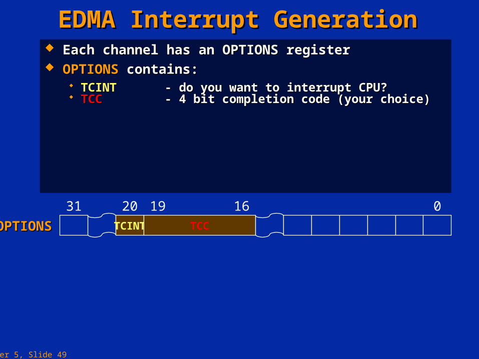
Each channel has an Each channel has an OPTIONSOPTIONS register register OPTIONSOPTIONS contains: contains:
TCINTTCINT - do you want to interrupt CPU?- do you want to interrupt CPU? TCC TCC - 4 bit completion code (your choice)- 4 bit completion code (your choice)
Chapter 5, Slide 50
EDMA Interrupt GenerationEDMA Interrupt Generation
TCINT TCC
31 20 19 16 0
OPTIONSOPTIONS
Each channel has an Each channel has an OPTIONSOPTIONS register register OPTIONSOPTIONS contains: contains:
TCINTTCINT - do you want to interrupt CPU?- do you want to interrupt CPU? TCC TCC - 4 bit completion code (your choice)- 4 bit completion code (your choice)
Upon completion:Upon completion: If you set TCINT = 1, then CIPR bit equal toIf you set TCINT = 1, then CIPR bit equal to TCC value (you set) is set to oneTCC value (you set) is set to one
rsvd CIP15 CIP14 CIP8 CIP7 CIP6 CIP5 CIP4 CIP3 CIP2 CIP1 CIP0
31 15 14 8 7 6 5 4 3 2 1 0
CIPRCIPR
Chapter 5, Slide 51
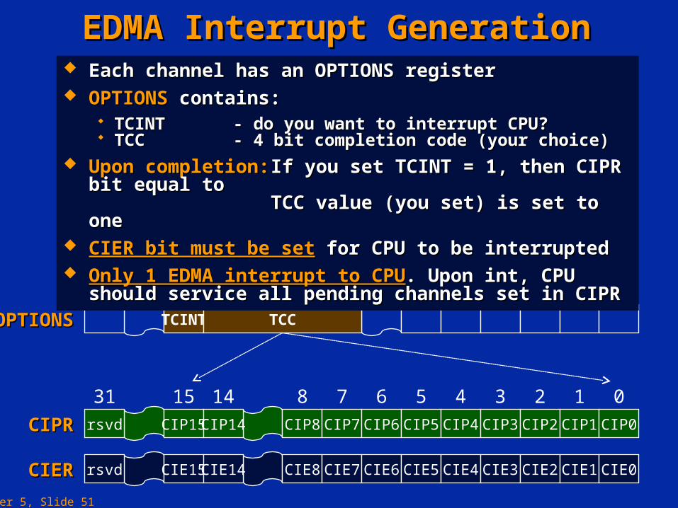
EDMA Interrupt GenerationEDMA Interrupt Generation
TCINT TCC
31 20 19 16 0
OPTIONSOPTIONS
Each channel has an Each channel has an OPTIONSOPTIONS register register OPTIONSOPTIONS contains: contains:
TCINTTCINT - do you want to interrupt CPU?- do you want to interrupt CPU? TCC TCC - 4 bit completion code (your choice)- 4 bit completion code (your choice)
Upon completion:Upon completion: If you set TCINT = 1, then CIPR bit equal toIf you set TCINT = 1, then CIPR bit equal to TCC value (you set) is set to oneTCC value (you set) is set to one
CIER bit must be setCIER bit must be set for CPU to be interrupted for CPU to be interrupted Only 1 EDMA interrupt to CPUOnly 1 EDMA interrupt to CPU. Upon int, CPU should service all . Upon int, CPU should service all
pending channels set in CIPRpending channels set in CIPR
rsvd CIP15 CIP14 CIP8 CIP7 CIP6 CIP5 CIP4 CIP3 CIP2 CIP1 CIP0
31 15 14 8 7 6 5 4 3 2 1 0
CIPRCIPR
CIERCIER rsvd CIE15 CIE14 CIE8 CIE7 CIE6 CIE5 CIE4 CIE3 CIE2 CIE1 CIE0
Chapter 5, Slide 52
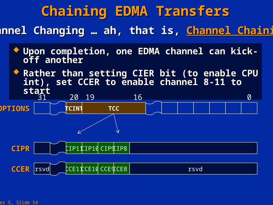
Chaining EDMA TransfersChaining EDMA Transfers
After completion of an EDMA channel transfer another EDMA channel transfer can be triggered.After completion of an EDMA channel transfer another EDMA channel transfer can be triggered. This triggering mechanism is similar to event triggering.This triggering mechanism is similar to event triggering. However this method can only be used to trigger EDMA channels 8 to 11.However this method can only be used to trigger EDMA channels 8 to 11.
Chapter 5, Slide 53
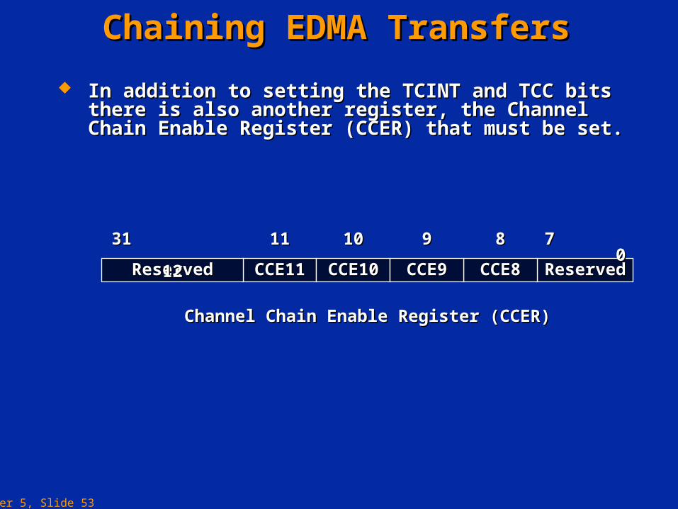
Chaining EDMA TransfersChaining EDMA Transfers
In addition to setting the TCINT and TCC bits there is also In addition to setting the TCINT and TCC bits there is also another register, the Channel Chain Enable Register another register, the Channel Chain Enable Register (CCER) that must be set.(CCER) that must be set.
CCE11CCE11 CCE10CCE10 ReservedReservedCCE8CCE8CCE9CCE9ReservedReserved
1111 1010 7 07 0889931 31 1212
Channel Chain Enable Register (CCER)Channel Chain Enable Register (CCER)
Chapter 5, Slide 54
Chaining EDMA TransfersChaining EDMA TransfersChannel Changing … ah, that is, Channel Changing … ah, that is, Channel ChainingChannel Chaining
CCERCCER rsvd CCE11CCE10 CCE8 rsvd CCE9
Upon completion, one EDMA channel can kick-off anotherUpon completion, one EDMA channel can kick-off another Rather than setting CIER bit (to enable CPU int), set CCER Rather than setting CIER bit (to enable CPU int), set CCER
to enable channel 8-11 to startto enable channel 8-11 to start
TCINT TCC
31 20 19 16 0
OPTIONSOPTIONS
CIPRCIPR CIP11 CIP10 CIP8 CIP9
Chapter 5, Slide 55
EDMA Interrupt GenerationEDMA Interrupt GenerationE V T15 E V T14 E V T0E V T1
R E V T1 XE V T1 T IN T0 D S P IN T
E E 15 E E 14 E E 0E E 1
T riggers
C om plete
C hanne l 15
T riggers
C om plete
C hanne l 14
T riggers
C om plete
C hanne l 1
T riggers
C om plete
C hanne l 0
TC IN T TC C
D ecoder
4
E D M A _IN T
E S R 14E S R 15 E S R 1 E S R 0
TC IN T TC C
D ecoder
4
E V T11
E E 11
T riggers
C om plete
C hanne l 11
E V T8
E E 8
T riggers
C om plete
C hanne l 8
E S R 11 E S R 8C C 11 C C 8
C IP 15 C IP 14 C IP 0C IP 1C IP 11
C C E 11
C IP 8
C C E 8
C IE 15 C IE 14 C IE 0C IE 1C IE 11 C IE 8
C C 11 C C 8
Event Register(ER)
Event Enable Register(EER)
Channel InterruptPending Register (CIPR)
Channel Chain EnableRegister (CCER)
Channel InterruptEnable Register (CIER)
Chapter 5, Slide 56
OptionsOptions
SourceSource
DestinationDestination
IndexIndex
Link AddrLink AddrCount ReloadCount Reload
3131 1616 1515 00
Transfer CountTransfer Count
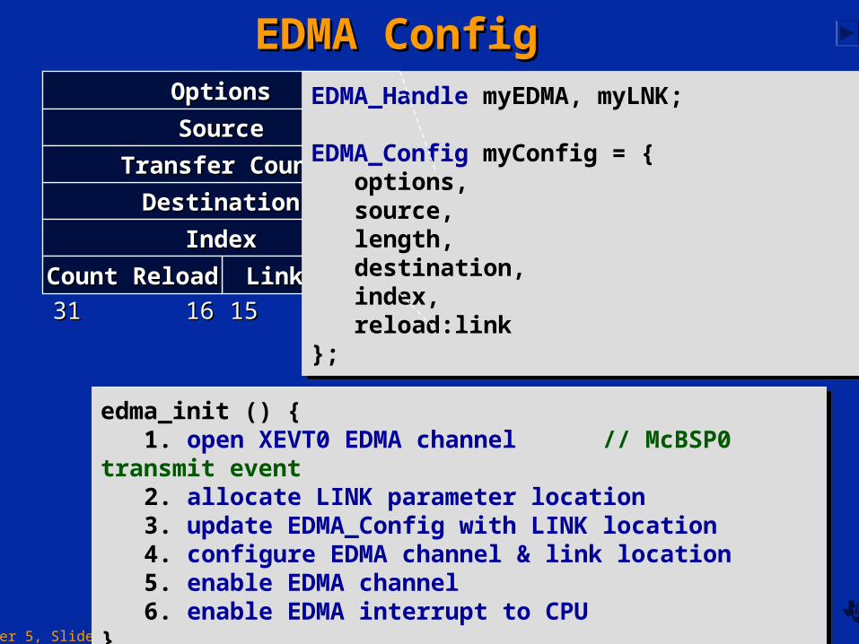
EDMA_Handle myEDMA, myLNK;
EDMA_Config myConfig = {options, source, length, destination,index, reload:link
};
EDMA_Handle myEDMA, myLNK;
EDMA_Config myConfig = {options, source, length, destination,index, reload:link
};
edma_init () {1. open XEVT0 EDMA channel // McBSP0 transmit event
2. allocate LINK parameter location 3. update EDMA_Config with LINK location4. configure EDMA channel & link location 5. enable EDMA channel6. enable EDMA interrupt to CPU
}
edma_init () {1. open XEVT0 EDMA channel // McBSP0 transmit event
2. allocate LINK parameter location 3. update EDMA_Config with LINK location4. configure EDMA channel & link location 5. enable EDMA channel6. enable EDMA interrupt to CPU
}
EDMA ConfigEDMA Config
Chapter 5, Slide 57
OptionsOptions
SourceSource
DestinationDestination
IndexIndex
Link AddrLink AddrCount ReloadCount Reload
3131 1616 1515 00
Transfer CountTransfer Count
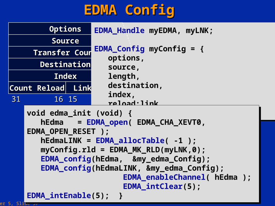
EDMA_Handle myEDMA, myLNK;
EDMA_Config myConfig = {options, source, length, destination,index, reload:link
};
EDMA_Handle myEDMA, myLNK;
EDMA_Config myConfig = {options, source, length, destination,index, reload:link
};
EDMA ConfigEDMA Config
void edma_init (void) {hEdma = EDMA_open( EDMA_CHA_XEVT0, EDMA_OPEN_RESET );hEdmaLINK = EDMA_allocTable( -1 ); myConfig.rld = EDMA_MK_RLD(myLNK,0);EDMA_config(hEdma, &my_edma_Config);EDMA_config(hEdmaLINK, &my_edma_Config);
EDMA_enableChannel( hEdma ); EDMA_intClear(5); EDMA_intEnable(5); }
void edma_init (void) {hEdma = EDMA_open( EDMA_CHA_XEVT0, EDMA_OPEN_RESET );hEdmaLINK = EDMA_allocTable( -1 ); myConfig.rld = EDMA_MK_RLD(myLNK,0);EDMA_config(hEdma, &my_edma_Config);EDMA_config(hEdmaLINK, &my_edma_Config);
EDMA_enableChannel( hEdma ); EDMA_intClear(5); EDMA_intEnable(5); }
Chapter 5, Slide 58
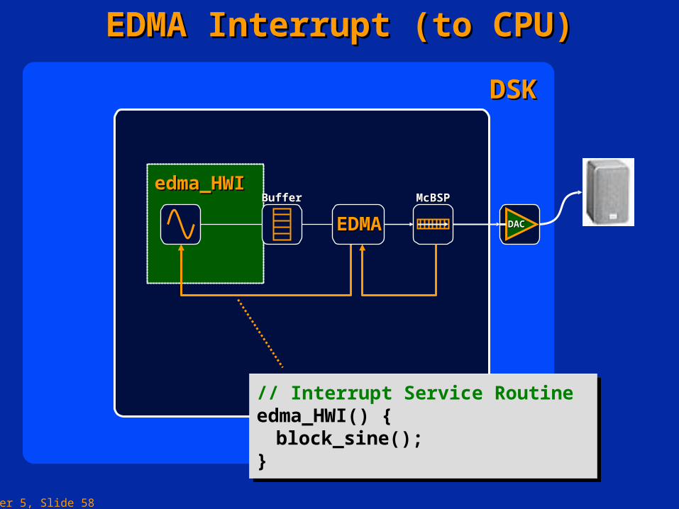
DSKDSK
edma_HWI edma_HWI
DACDAC
McBSPMcBSP
EDMA Interrupt (to CPU)EDMA Interrupt (to CPU)
// Interrupt Service Routineedma_HWI() { block_sine();}
// Interrupt Service Routineedma_HWI() { block_sine();}
BufferBuffer
EDMAEDMA
Chapter 5, Slide 59
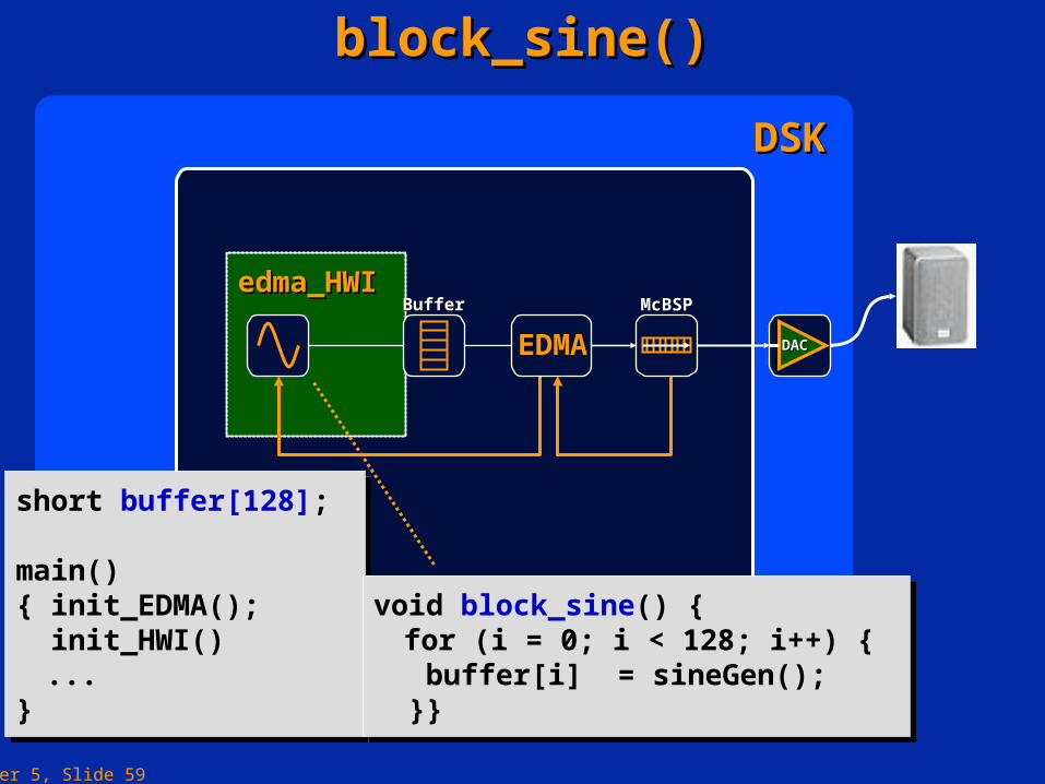
DSKDSK
edma_HWI edma_HWI
DACDAC
McBSPMcBSP
block_sine()block_sine()
BufferBuffer
EDMAEDMA
short buffer[128];
main(){ init_EDMA(); init_HWI() ...}
short buffer[128];
main(){ init_EDMA(); init_HWI() ...}
void block_sine() { for (i = 0; i < 128; i++) { buffer[i] = sineGen(); }}
void block_sine() { for (i = 0; i < 128; i++) { buffer[i] = sineGen(); }}
Chapter 5, Slide 60
Introduction to the Quick DMA (QDMA)Introduction to the Quick DMA (QDMA)
The QDMA provides a very efficient way of moving data.The QDMA provides a very efficient way of moving data. It supports nearly all the same modes as the EDMA however transfer requests are submitted faster.It supports nearly all the same modes as the EDMA however transfer requests are submitted faster. However it does not support reload of a count or link.However it does not support reload of a count or link. Therefore the QDMA is suited to one-off moves of blocks of data internally whereas the EDMA is suited to moving data between Therefore the QDMA is suited to one-off moves of blocks of data internally whereas the EDMA is suited to moving data between
peripherals and the memory.peripherals and the memory.
Chapter 5, Slide 61
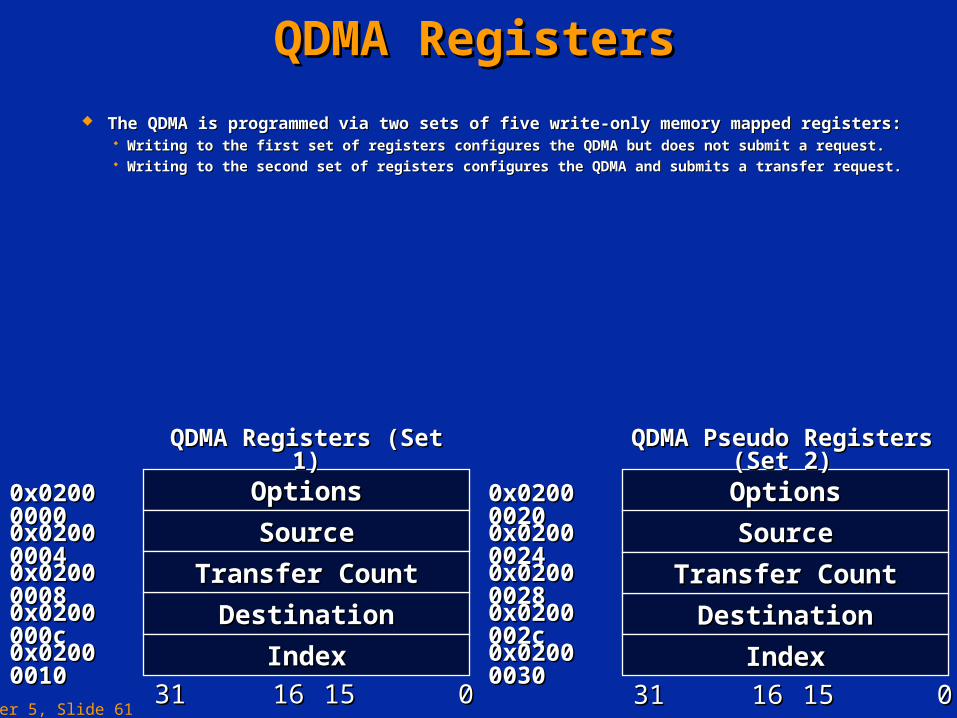
QDMA RegistersQDMA Registers
The QDMA is programmed via two sets of five write-only memory mapped registers:The QDMA is programmed via two sets of five write-only memory mapped registers: Writing to the first set of registers configures the QDMA but does not submit a request.Writing to the first set of registers configures the QDMA but does not submit a request. Writing to the second set of registers configures the QDMA and submits a transfer request.Writing to the second set of registers configures the QDMA and submits a transfer request.
OptionsOptions
SourceSource
DestinationDestination
IndexIndex
3131 1616 1515 00
Transfer CountTransfer Count
OptionsOptions
SourceSource
DestinationDestination
IndexIndex
3131 1616 1515 00
Transfer CountTransfer Count
0x0200 00000x0200 0000
0x0200 00040x0200 0004
0x0200 00080x0200 0008
0x0200 000c0x0200 000c
0x0200 00100x0200 0010
0x0200 00200x0200 0020
0x0200 00240x0200 0024
0x0200 00280x0200 0028
0x0200 002c0x0200 002c
0x0200 00300x0200 0030
QDMA Registers (Set 1)QDMA Registers (Set 1) QDMA Pseudo Registers (Set 2)QDMA Pseudo Registers (Set 2)
Chapter 5, Slide 62
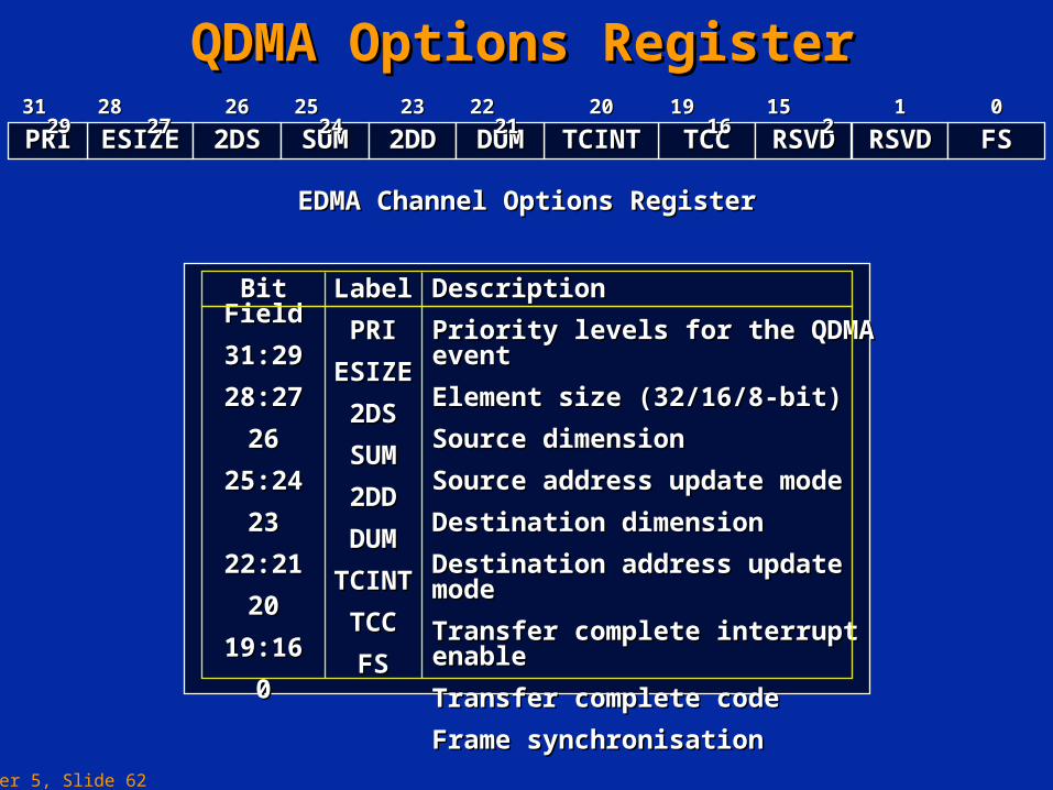
QDMA Options RegisterQDMA Options Register
EDMA Channel Options RegisterEDMA Channel Options Register
ESIZEESIZE 2DS2DS TCCTCCTCINTTCINTSUMSUMPRIPRI31 2931 29
2DD2DD DUMDUM RSVDRSVD FSFS28 2728 27 2626 25 2425 24 2323 22 2122 21 2020 19 1619 16 11 00
RSVDRSVD15 215 2
Bit FieldBit Field
31:2931:29
28:2728:27
2626
25:2425:24
2323
22:2122:21
2020
19:1619:16
00
LabelLabel
PRIPRI
ESIZEESIZE
2DS2DS
SUMSUM
2DD2DD
DUMDUM
TCINTTCINT
TCCTCC
FSFS
DescriptionDescription
Priority levels for the QDMA eventPriority levels for the QDMA event
Element size (32/16/8-bit)Element size (32/16/8-bit)
Source dimensionSource dimension
Source address update modeSource address update mode
Destination dimensionDestination dimension
Destination address update modeDestination address update mode
Transfer complete interrupt enableTransfer complete interrupt enable
Transfer complete codeTransfer complete code
Frame synchronisationFrame synchronisation
Chapter 5, Slide 63
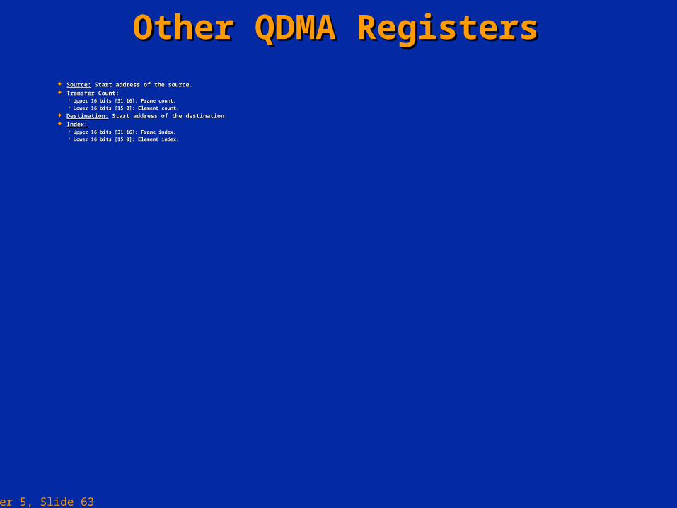
Other QDMA RegistersOther QDMA Registers Source:Source: Start address of the source. Start address of the source. Transfer Count:Transfer Count:
Upper 16 bits [31:16]: Frame count.Upper 16 bits [31:16]: Frame count. Lower 16 bits [15:0]: Element count.Lower 16 bits [15:0]: Element count.
Destination:Destination: Start address of the destination. Start address of the destination. Index:Index:
Upper 16 bits [31:16]: Frame index.Upper 16 bits [31:16]: Frame index. Lower 16 bits [15:0]: Element index.Lower 16 bits [15:0]: Element index.
Chapter 5, Slide 64
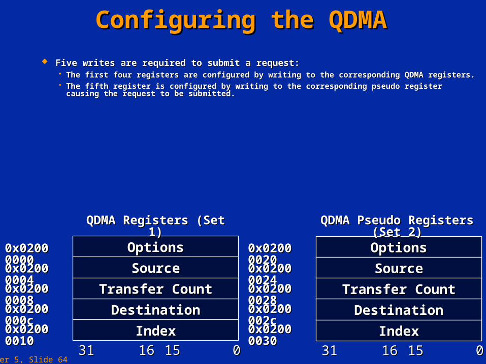
Configuring the QDMAConfiguring the QDMA
Five writes are required to submit a request:Five writes are required to submit a request: The first four registers are configured by writing to the corresponding QDMA registers.The first four registers are configured by writing to the corresponding QDMA registers. The fifth register is configured by writing to the corresponding pseudo register causing the request to be The fifth register is configured by writing to the corresponding pseudo register causing the request to be
submitted.submitted.
OptionsOptions
SourceSource
DestinationDestination
IndexIndex
3131 1616 1515 00
Transfer CountTransfer Count
OptionsOptions
SourceSource
DestinationDestination
IndexIndex
3131 1616 1515 00
Transfer CountTransfer Count
0x0200 00000x0200 0000
0x0200 00040x0200 0004
0x0200 00080x0200 0008
0x0200 000c0x0200 000c
0x0200 00100x0200 0010
0x0200 00200x0200 0020
0x0200 00240x0200 0024
0x0200 00280x0200 0028
0x0200 002c0x0200 002c
0x0200 00300x0200 0030
QDMA Registers (Set 1)QDMA Registers (Set 1) QDMA Pseudo Registers (Set 2)QDMA Pseudo Registers (Set 2)
Chapter 5, Slide 65
Features of the QDMAFeatures of the QDMA
All transfers are frame synchronised.All transfers are frame synchronised. Although linking is not supported, completion interrupts and channel chaining are supported.Although linking is not supported, completion interrupts and channel chaining are supported. The values held in the registers are not changed by the hardware hence the same transfer can be repeated The values held in the registers are not changed by the hardware hence the same transfer can be repeated
by a single write to one of the pseudo registers.by a single write to one of the pseudo registers.
Chapter 5, Slide 66
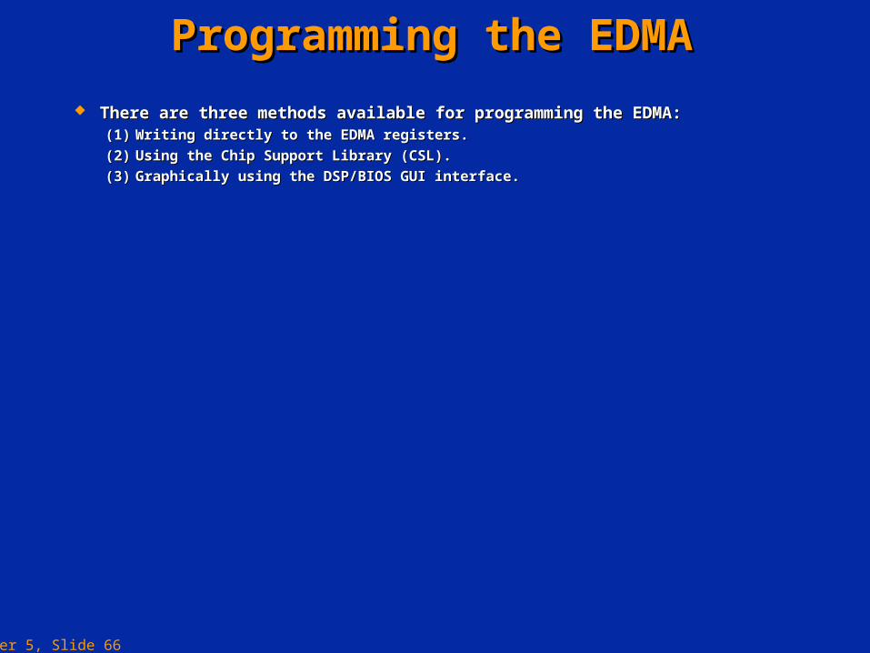
Programming the EDMAProgramming the EDMA
There are three methods available for programming the EDMA:There are three methods available for programming the EDMA:(1)(1) Writing directly to the EDMA registers.Writing directly to the EDMA registers.
(2)(2) Using the Chip Support Library (CSL).Using the Chip Support Library (CSL).
(3)(3) Graphically using the DSP/BIOS GUI interface.Graphically using the DSP/BIOS GUI interface.
Chapter 5, Slide 67
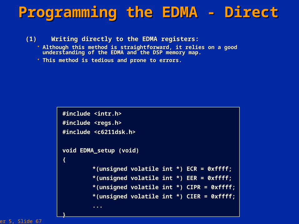
Programming the EDMA - DirectProgramming the EDMA - Direct
(1)(1) Writing directly to the EDMA registers:Writing directly to the EDMA registers: Although this method is straightforward, it relies on a good understanding of the EDMA and the Although this method is straightforward, it relies on a good understanding of the EDMA and the
DSP memory map.DSP memory map. This method is tedious and prone to errors.This method is tedious and prone to errors.
#include <intr.h>#include <intr.h>
#include <regs.h>#include <regs.h>
#include <c6211dsk.h>#include <c6211dsk.h>
void EDMA_setup (void)void EDMA_setup (void)
{{
*(unsigned volatile int *) ECR = 0xffff;*(unsigned volatile int *) ECR = 0xffff;
*(unsigned volatile int *) EER = 0xffff;*(unsigned volatile int *) EER = 0xffff;
*(unsigned volatile int *) CIPR = 0xffff;*(unsigned volatile int *) CIPR = 0xffff;
*(unsigned volatile int *) CIER = 0xffff;*(unsigned volatile int *) CIER = 0xffff;
......
}}
Chapter 5, Slide 68
Programming the EDMA - CSLProgramming the EDMA - CSL
(2)(2) Using the Chip Support Library:Using the Chip Support Library: The CSL provides a C language interface for configuring and controlling the on-chip peripherals, in this case the EDMA.The CSL provides a C language interface for configuring and controlling the on-chip peripherals, in this case the EDMA. The library is modular with each module corresponding to a specific peripheral. This has the advantage of reducing the code size.The library is modular with each module corresponding to a specific peripheral. This has the advantage of reducing the code size. Some modules rely on other modules also being included, for example the IRQ module is required when using the EDMA module.Some modules rely on other modules also being included, for example the IRQ module is required when using the EDMA module.
Chapter 5, Slide 69
Programming the EDMA - CSLProgramming the EDMA - CSL
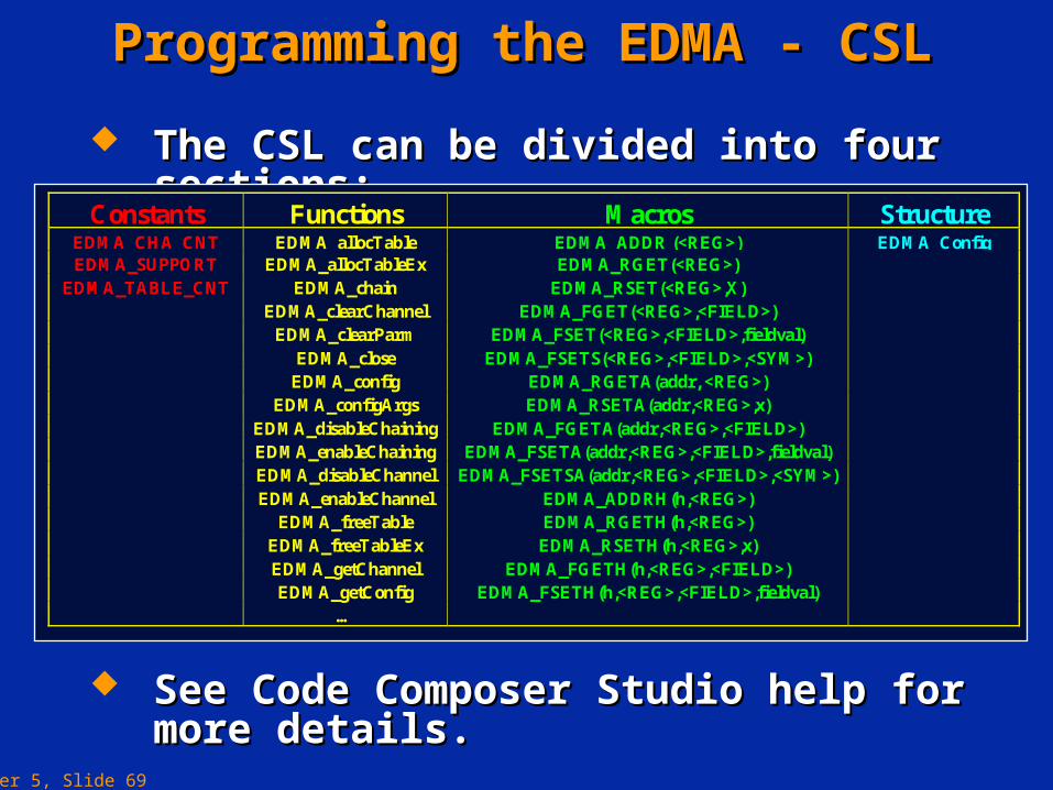
The CSL can be divided into four sections:The CSL can be divided into four sections:
Constants Functions Macros StructureEDMA_CHA_CNT EDMA_allocTable EDMA_ADDR (<REG>) EDMA_ConfigEDMA_SUPPORT EDMA_allocTableEx EDMA_RGET(<REG>)
EDMA_TABLE_CNT EDMA_chain EDMA_RSET(<REG>,X)EDMA_clearChannel EDMA_FGET(<REG>,<FIELD>)
EDMA_clearParm EDMA_FSET(<REG>,<FIELD>,fieldval)EDMA_close EDMA_FSETS(<REG>,<FIELD>,<SYM>)
EDMA_config EDMA_RGETA(addr, <REG>)EDMA_configArgs EDMA_RSETA(addr,<REG>,x)
EDMA_disableChaining EDMA_FGETA(addr,<REG>,<FIELD>)EDMA_enableChaining EDMA_FSETA(addr,<REG>,<FIELD>,fieldval)EDMA_disableChannel EDMA_FSETSA(addr,<REG>,<FIELD>,<SYM>)EDMA_enableChannel EDMA_ADDRH(h,<REG>)
EDMA_freeTable EDMA_RGETH(h,<REG>)EDMA_freeTableEx EDMA_RSETH(h,<REG>,x)EDMA_getChannel EDMA_FGETH(h,<REG>,<FIELD>)EDMA_getConfig EDMA_FSETH(h,<REG>,<FIELD>,fieldval)
…
See Code Composer Studio help for more details.See Code Composer Studio help for more details.
Chapter 5, Slide 70
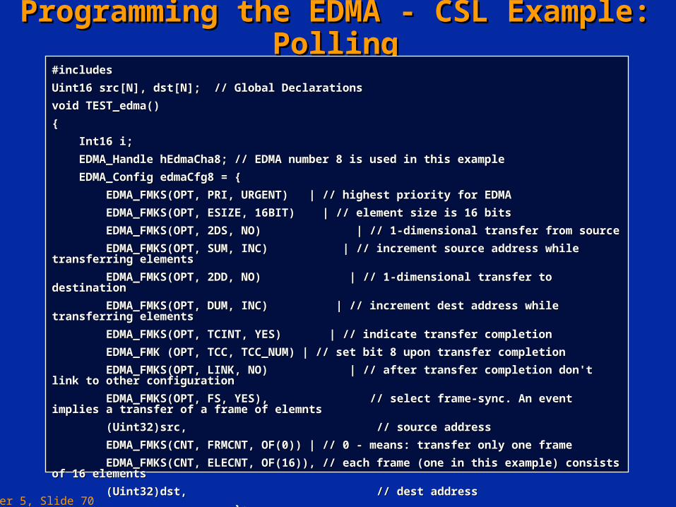
Programming the EDMA - CSL Example: PollingProgramming the EDMA - CSL Example: Polling#includes#includes
Uint16 src[N], dst[N]; // Global DeclarationsUint16 src[N], dst[N]; // Global Declarations
void TEST_edma()void TEST_edma()
{{
Int16 i;Int16 i;
EDMA_Handle hEdmaCha8; // EDMA number 8 is used in this exampleEDMA_Handle hEdmaCha8; // EDMA number 8 is used in this example
EDMA_Config edmaCfg8 = {EDMA_Config edmaCfg8 = {
EDMA_FMKS(OPT, PRI, URGENT) | // highest priority for EDMAEDMA_FMKS(OPT, PRI, URGENT) | // highest priority for EDMA
EDMA_FMKS(OPT, ESIZE, 16BIT) | // element size is 16 bitsEDMA_FMKS(OPT, ESIZE, 16BIT) | // element size is 16 bits
EDMA_FMKS(OPT, 2DS, NO) | // 1-dimensional transfer from sourceEDMA_FMKS(OPT, 2DS, NO) | // 1-dimensional transfer from source
EDMA_FMKS(OPT, SUM, INC) | // increment source address while transferring elementsEDMA_FMKS(OPT, SUM, INC) | // increment source address while transferring elements
EDMA_FMKS(OPT, 2DD, NO) | // 1-dimensional transfer to destinationEDMA_FMKS(OPT, 2DD, NO) | // 1-dimensional transfer to destination
EDMA_FMKS(OPT, DUM, INC) | // increment dest address while transferring elementsEDMA_FMKS(OPT, DUM, INC) | // increment dest address while transferring elements
EDMA_FMKS(OPT, TCINT, YES) | // indicate transfer completionEDMA_FMKS(OPT, TCINT, YES) | // indicate transfer completion
EDMA_FMK (OPT, TCC, TCC_NUM) | // set bit 8 upon transfer completionEDMA_FMK (OPT, TCC, TCC_NUM) | // set bit 8 upon transfer completion
EDMA_FMKS(OPT, LINK, NO) | // after transfer completion don't link to other configurationEDMA_FMKS(OPT, LINK, NO) | // after transfer completion don't link to other configuration
EDMA_FMKS(OPT, FS, YES),EDMA_FMKS(OPT, FS, YES), // select frame-sync. An event implies a transfer of a frame of elemnts // select frame-sync. An event implies a transfer of a frame of elemnts
(Uint32)src,(Uint32)src, // source address // source address
EDMA_FMKS(CNT, FRMCNT, OF(0)) | // 0 - means: transfer only one frameEDMA_FMKS(CNT, FRMCNT, OF(0)) | // 0 - means: transfer only one frame
EDMA_FMKS(CNT, ELECNT, OF(16)), // each frame (one in this example) consists of 16 elementsEDMA_FMKS(CNT, ELECNT, OF(16)), // each frame (one in this example) consists of 16 elements
(Uint32)dst,(Uint32)dst, // dest address // dest address
};};
… … // to be continued// to be continued

Chapter 5, Slide 71
Programming the EDMA - CSL Example : PollingProgramming the EDMA - CSL Example : Polling/* Set src values and clear destination *//* Set src values and clear destination */
for (i = 0; i < N; i++) {for (i = 0; i < N; i++) {
src[i] = i; src[i] = i;
dst[i] = 0;dst[i] = 0;
}}
/* Configure EDMA *//* Configure EDMA */
hEdmaCha8 = EDMA_open(8, EDMA_OPEN_RESET);hEdmaCha8 = EDMA_open(8, EDMA_OPEN_RESET);
EDMA_config(hEdmaCha8, &edmaCfg8);EDMA_config(hEdmaCha8, &edmaCfg8);
/* Start CPU initiated EDMA transfer by setting bit 24 in ESR *//* Start CPU initiated EDMA transfer by setting bit 24 in ESR */
EDMA_setChannel(hEdmaCha8);EDMA_setChannel(hEdmaCha8);
/* Poll EDMA interrupt to see if its done *//* Poll EDMA interrupt to see if its done */
while (!EDMA_intTest(TCC_NUM));while (!EDMA_intTest(TCC_NUM));
{{
;;
}}
/* We are done, so close EDMA channel *//* We are done, so close EDMA channel */
EDMA_close(hEdmaCha8);EDMA_close(hEdmaCha8);
/* Check data *//* Check data */
for (i = 0; i < N; i++)for (i = 0; i < N; i++)
if (dst[i] != src[i]){if (dst[i] != src[i]){
printf("failed\n"); }printf("failed\n"); }
/* Test passed *//* Test passed */
printf("success\n");printf("success\n");
}}
Chapter 5, Slide 72
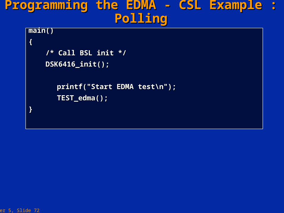
Programming the EDMA - CSL Example : PollingProgramming the EDMA - CSL Example : Pollingmain()main()
{{
/* Call BSL init *//* Call BSL init */
DSK6416_init();DSK6416_init();
printf("Start EDMA test\n");printf("Start EDMA test\n");
TEST_edma();TEST_edma();
}}

Chapter 5, Slide 73
Programming the EDMA - CSL Example : IntProgramming the EDMA - CSL Example : Int#includes#includes
Uint16 src[N], dst[N]; // Global DeclarationsUint16 src[N], dst[N]; // Global Declarations
void TEST_edma()void TEST_edma()
{{
Int16 i;Int16 i;
EDMA_Handle hEdmaCha8; // EDMA number 8 is used in this exampleEDMA_Handle hEdmaCha8; // EDMA number 8 is used in this example
EDMA_Config edmaCfg8 = {EDMA_Config edmaCfg8 = {
EDMA_FMKS(OPT, PRI, URGENT) | // highest priority for EDMAEDMA_FMKS(OPT, PRI, URGENT) | // highest priority for EDMA
EDMA_FMKS(OPT, ESIZE, 16BIT) | // element size is 16 bitsEDMA_FMKS(OPT, ESIZE, 16BIT) | // element size is 16 bits
EDMA_FMKS(OPT, 2DS, NO) | // 1-dimensional transfer from sourceEDMA_FMKS(OPT, 2DS, NO) | // 1-dimensional transfer from source
EDMA_FMKS(OPT, SUM, INC) | // increment source address while transferring elementsEDMA_FMKS(OPT, SUM, INC) | // increment source address while transferring elements
EDMA_FMKS(OPT, 2DD, NO) | // 1-dimensional transfer to destinationEDMA_FMKS(OPT, 2DD, NO) | // 1-dimensional transfer to destination
EDMA_FMKS(OPT, DUM, INC) | // increment dest address while transferring elementsEDMA_FMKS(OPT, DUM, INC) | // increment dest address while transferring elements
EDMA_FMKS(OPT, TCINT, YES) | // indicate transfer completionEDMA_FMKS(OPT, TCINT, YES) | // indicate transfer completion
EDMA_FMK (OPT, TCC, TCC_NUM) | // set bit 8 upon transfer completionEDMA_FMK (OPT, TCC, TCC_NUM) | // set bit 8 upon transfer completion
EDMA_FMKS(OPT, LINK, NO) | // after transfer completion don't link to other configurationEDMA_FMKS(OPT, LINK, NO) | // after transfer completion don't link to other configuration
EDMA_FMKS(OPT, FS, YES),EDMA_FMKS(OPT, FS, YES), // select frame-sync. An event implies a transfer of a frame of elemnts // select frame-sync. An event implies a transfer of a frame of elemnts
(Uint32)src,(Uint32)src, // source address// source address
EDMA_FMKS(CNT, FRMCNT, OF(0)) | // 0 - means: transfer only one frameEDMA_FMKS(CNT, FRMCNT, OF(0)) | // 0 - means: transfer only one frame
EDMA_FMKS(CNT, ELECNT, OF(16)), // each frame (one in this example) consists of 16 elementsEDMA_FMKS(CNT, ELECNT, OF(16)), // each frame (one in this example) consists of 16 elements
(Uint32)dst,(Uint32)dst, // dest address// dest address
};};
… … //to be continued//to be continued

Chapter 5, Slide 74
Programming the EDMA - CSL Example : IntProgramming the EDMA - CSL Example : Int /* Set src values and clear destination *//* Set src values and clear destination */
for (i = 0; i < N; i++) {for (i = 0; i < N; i++) {
src[i] = i; src[i] = i;
dst[i] = 0;dst[i] = 0;
}}
/* Configure EDMA *//* Configure EDMA */
hEdmaCha8 = EDMA_open (8, EDMA_OPEN_RESET);hEdmaCha8 = EDMA_open (8, EDMA_OPEN_RESET);
EDMA_config (hEdmaCha8, &edmaCfg8);EDMA_config (hEdmaCha8, &edmaCfg8);
EDMA_intEnable (TCC_NUM); // enable CIER bit 8 to cause a interrupt to CPUEDMA_intEnable (TCC_NUM); // enable CIER bit 8 to cause a interrupt to CPU
IRQ_clear (IRQ_EVT_EDMAINT); // clear any possible pending interruptsIRQ_clear (IRQ_EVT_EDMAINT); // clear any possible pending interrupts
IRQ_enable (IRQ_EVT_EDMAINT); // enable EDMA interrupt enterring CPUIRQ_enable (IRQ_EVT_EDMAINT); // enable EDMA interrupt enterring CPU
IRQ_globalEnable (); // actually, not necessary, since this is done by DSP/BIOSIRQ_globalEnable (); // actually, not necessary, since this is done by DSP/BIOS
/* Start CPU initiated EDMA transfer by setting bit 24 in ESR *//* Start CPU initiated EDMA transfer by setting bit 24 in ESR */
EDMA_setChannel (hEdmaCha8);EDMA_setChannel (hEdmaCha8);
}}
Chapter 5, Slide 75
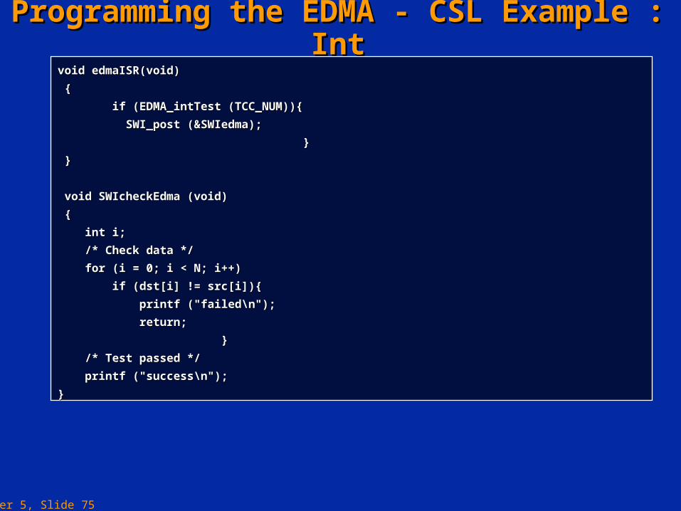
Programming the EDMA - CSL Example : IntProgramming the EDMA - CSL Example : Intvoid edmaISR(void)void edmaISR(void)
{{
if (EDMA_intTest (TCC_NUM)){if (EDMA_intTest (TCC_NUM)){
SWI_post (&SWIedma);SWI_post (&SWIedma);
}}
}}
void SWIcheckEdma (void)void SWIcheckEdma (void)
{{
int i;int i;
/* Check data *//* Check data */
for (i = 0; i < N; i++)for (i = 0; i < N; i++)
if (dst[i] != src[i]){if (dst[i] != src[i]){
printf ("failed\n");printf ("failed\n");
return;return;
}}
/* Test passed *//* Test passed */
printf ("success\n");printf ("success\n");
}}
Chapter 5, Slide 76
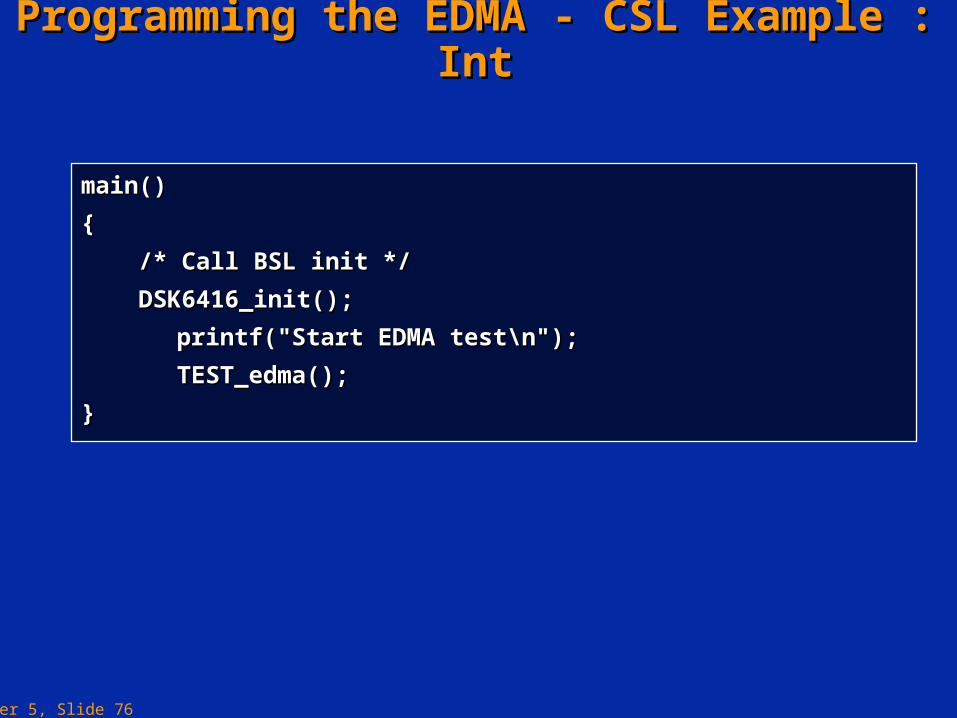
Programming the EDMA - CSL Example : IntProgramming the EDMA - CSL Example : Int
main()main()
{{
/* Call BSL init *//* Call BSL init */
DSK6416_init();DSK6416_init();
printf("Start EDMA test\n");printf("Start EDMA test\n");
TEST_edma();TEST_edma();
}}
Chapter 5, Slide 77
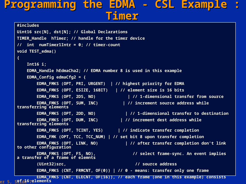
Programming the EDMA - CSL Example : TimerProgramming the EDMA - CSL Example : Timer#includes#includes
Uint16 src[N], dst[N]; // Global DeclarationsUint16 src[N], dst[N]; // Global Declarations
TIMER_Handle hTimer; // handle for the timer deviceTIMER_Handle hTimer; // handle for the timer device
// int numTimer1Intr = 0; // timer-count// int numTimer1Intr = 0; // timer-count
void TEST_edma()void TEST_edma()
{{
Int16 i;Int16 i;
EDMA_Handle hEdmaCha2; // EDMA number 8 is used in this exampleEDMA_Handle hEdmaCha2; // EDMA number 8 is used in this example
EDMA_Config edmaCfg2 = {EDMA_Config edmaCfg2 = {
EDMA_FMKS (OPT, PRI, URGENT) | // highest priority for EDMAEDMA_FMKS (OPT, PRI, URGENT) | // highest priority for EDMA
EDMA_FMKS (OPT, ESIZE, 16BIT) | // element size is 16 bitsEDMA_FMKS (OPT, ESIZE, 16BIT) | // element size is 16 bits
EDMA_FMKS (OPT, 2DS, NO) | // 1-dimensional transfer from sourceEDMA_FMKS (OPT, 2DS, NO) | // 1-dimensional transfer from source
EDMA_FMKS (OPT, SUM, INC) | // increment source address while transferring elementsEDMA_FMKS (OPT, SUM, INC) | // increment source address while transferring elements
EDMA_FMKS (OPT, 2DD, NO) | // 1-dimensional transfer to destinationEDMA_FMKS (OPT, 2DD, NO) | // 1-dimensional transfer to destination
EDMA_FMKS (OPT, DUM, INC) | // increment dest address while transferring elementsEDMA_FMKS (OPT, DUM, INC) | // increment dest address while transferring elements
EDMA_FMKS (OPT, TCINT, YES) | // indicate transfer completionEDMA_FMKS (OPT, TCINT, YES) | // indicate transfer completion
EDMA_FMK (OPT, TCC, TCC_NUM) | // set bit 8 upon transfer completionEDMA_FMK (OPT, TCC, TCC_NUM) | // set bit 8 upon transfer completion
EDMA_FMKS (OPT, LINK, NO) | // after transfer completion don't link to other configurationEDMA_FMKS (OPT, LINK, NO) | // after transfer completion don't link to other configuration
EDMA_FMKS (OPT, FS, NO),EDMA_FMKS (OPT, FS, NO), // select frame-sync. An event implies a transfer of a frame of elemnts // select frame-sync. An event implies a transfer of a frame of elemnts
(Uint32)src,(Uint32)src, // source address // source address
EDMA_FMKS (CNT, FRMCNT, OF(0)) | // 0 - means: transfer only one frameEDMA_FMKS (CNT, FRMCNT, OF(0)) | // 0 - means: transfer only one frame
EDMA_FMKS (CNT, ELECNT, OF(16)), // each frame (one in this example) consists of 16 elementsEDMA_FMKS (CNT, ELECNT, OF(16)), // each frame (one in this example) consists of 16 elements
(Uint32)dst,(Uint32)dst, // dest address // dest address
};};
Chapter 5, Slide 78
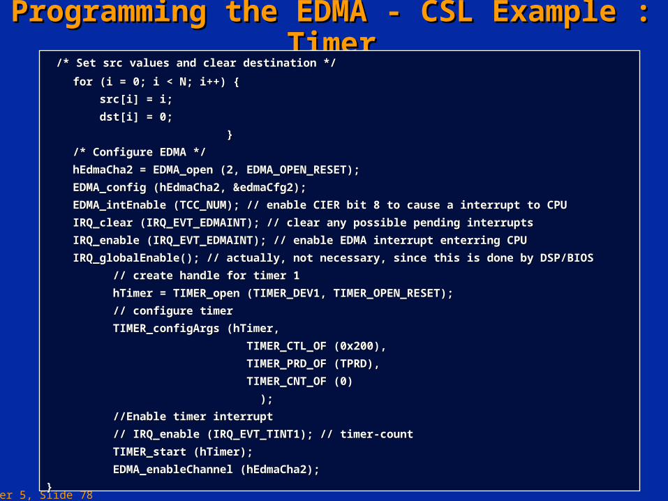
Programming the EDMA - CSL Example : TimerProgramming the EDMA - CSL Example : Timer /* Set src values and clear destination *//* Set src values and clear destination */
for (i = 0; i < N; i++) {for (i = 0; i < N; i++) {
src[i] = i; src[i] = i;
dst[i] = 0;dst[i] = 0;
}}
/* Configure EDMA *//* Configure EDMA */
hEdmaCha2 = EDMA_open (2, EDMA_OPEN_RESET);hEdmaCha2 = EDMA_open (2, EDMA_OPEN_RESET);
EDMA_config (hEdmaCha2, &edmaCfg2);EDMA_config (hEdmaCha2, &edmaCfg2);
EDMA_intEnable (TCC_NUM); // enable CIER bit 8 to cause a interrupt to CPUEDMA_intEnable (TCC_NUM); // enable CIER bit 8 to cause a interrupt to CPU
IRQ_clear (IRQ_EVT_EDMAINT); // clear any possible pending interruptsIRQ_clear (IRQ_EVT_EDMAINT); // clear any possible pending interrupts
IRQ_enable (IRQ_EVT_EDMAINT); // enable EDMA interrupt enterring CPUIRQ_enable (IRQ_EVT_EDMAINT); // enable EDMA interrupt enterring CPU
IRQ_globalEnable(); // actually, not necessary, since this is done by DSP/BIOSIRQ_globalEnable(); // actually, not necessary, since this is done by DSP/BIOS
// create handle for timer 1// create handle for timer 1
hTimer = TIMER_open (TIMER_DEV1, TIMER_OPEN_RESET);hTimer = TIMER_open (TIMER_DEV1, TIMER_OPEN_RESET);
// configure timer// configure timer
TIMER_configArgs (hTimer,TIMER_configArgs (hTimer,
TIMER_CTL_OF (0x200),TIMER_CTL_OF (0x200),
TIMER_PRD_OF (TPRD),TIMER_PRD_OF (TPRD),
TIMER_CNT_OF (0)TIMER_CNT_OF (0)
););
//Enable timer interrupt//Enable timer interrupt
// IRQ_enable (IRQ_EVT_TINT1); // timer-count// IRQ_enable (IRQ_EVT_TINT1); // timer-count
TIMER_start (hTimer);TIMER_start (hTimer);
EDMA_enableChannel (hEdmaCha2);EDMA_enableChannel (hEdmaCha2);
}}
Chapter 5, Slide 79
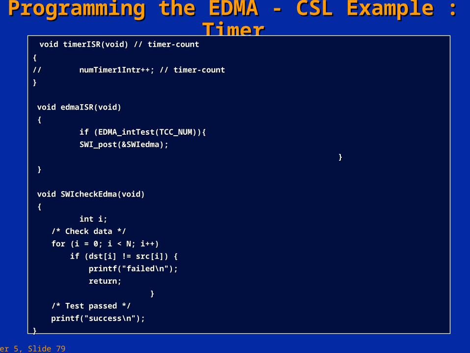
Programming the EDMA - CSL Example : TimerProgramming the EDMA - CSL Example : Timer void timerISR(void) // timer-countvoid timerISR(void) // timer-count
{{
// // numTimer1Intr++; // timer-countnumTimer1Intr++; // timer-count
}}
void edmaISR(void)void edmaISR(void)
{{
if (EDMA_intTest(TCC_NUM)){if (EDMA_intTest(TCC_NUM)){
SWI_post(&SWIedma);SWI_post(&SWIedma);
}}
}}
void SWIcheckEdma(void)void SWIcheckEdma(void)
{{
int i;int i;
/* Check data *//* Check data */
for (i = 0; i < N; i++)for (i = 0; i < N; i++)
if (dst[i] != src[i]) {if (dst[i] != src[i]) {
printf("failed\n");printf("failed\n");
return;return;
}}
/* Test passed *//* Test passed */
printf("success\n");printf("success\n");
}}
Chapter 5, Slide 80
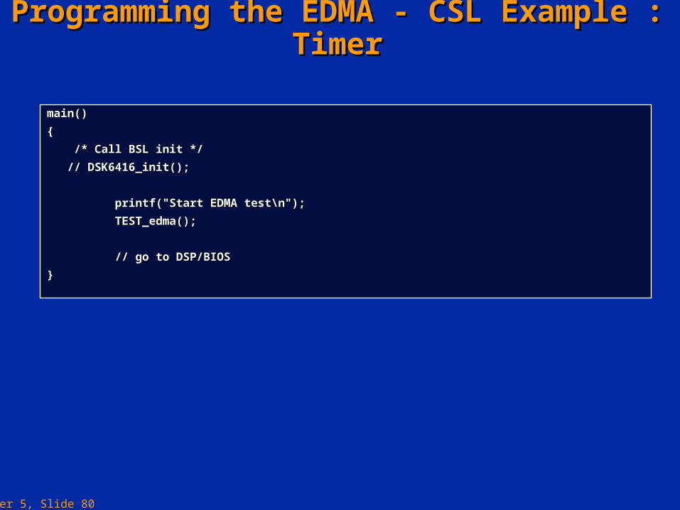
Programming the EDMA - CSL Example : TimerProgramming the EDMA - CSL Example : Timer
main()main()
{{
/* Call BSL init *//* Call BSL init */
// DSK6416_init();// DSK6416_init();
printf("Start EDMA test\n");printf("Start EDMA test\n");
TEST_edma();TEST_edma();
// go to DSP/BIOS// go to DSP/BIOS
}}
Chapter 5, Slide 81
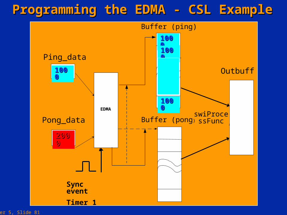
Programming the EDMA - CSL ExampleProgramming the EDMA - CSL Example
Ping_data
EDMA
Outbuff
swiProcessFunc
Buffer (ping)
Buffer (pong)Pong_data
Sync event
Timer 1
10001000
10001000
10001000
10001000
20002000

Chapter 5, Slide 82
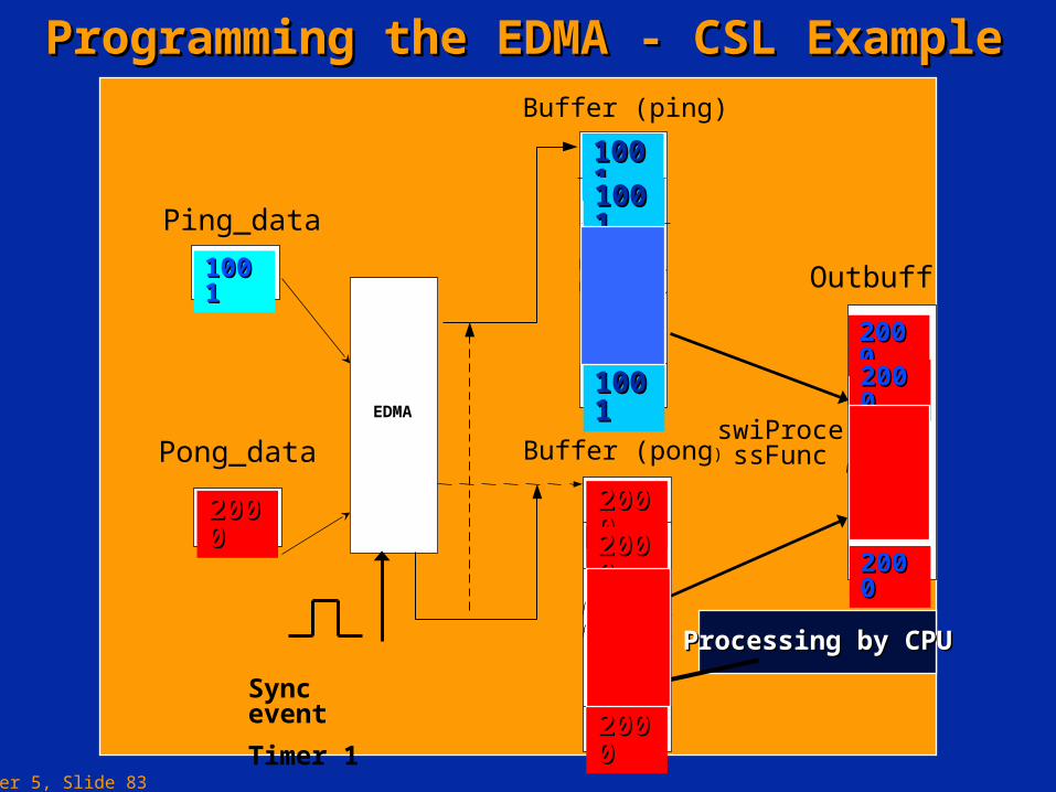
Programming the EDMA - CSL ExampleProgramming the EDMA - CSL Example
Ping_data
EDMA
Outbuff
swiProcessFunc
Buffer (ping)
Buffer (pong)Pong_data
Sync event
Timer 1
10001000
10001000
10001000
10001000
20002000 20002000
20002000
20002000
10001000
10001000
10001000
Processing by CPUProcessing by CPU
Chapter 5, Slide 83
Programming the EDMA - CSL ExampleProgramming the EDMA - CSL Example
Ping_data
EDMA
Outbuff
swiProcessFunc
Buffer (ping)
Buffer (pong)Pong_data
Sync event
Timer 1
10011001
10001000
10001000
10001000
20002000
10011001
10011001
10011001
20002000
20002000
20002000
Processing by CPUProcessing by CPU
20002000
20002000
20002000
Chapter 5, Slide 84
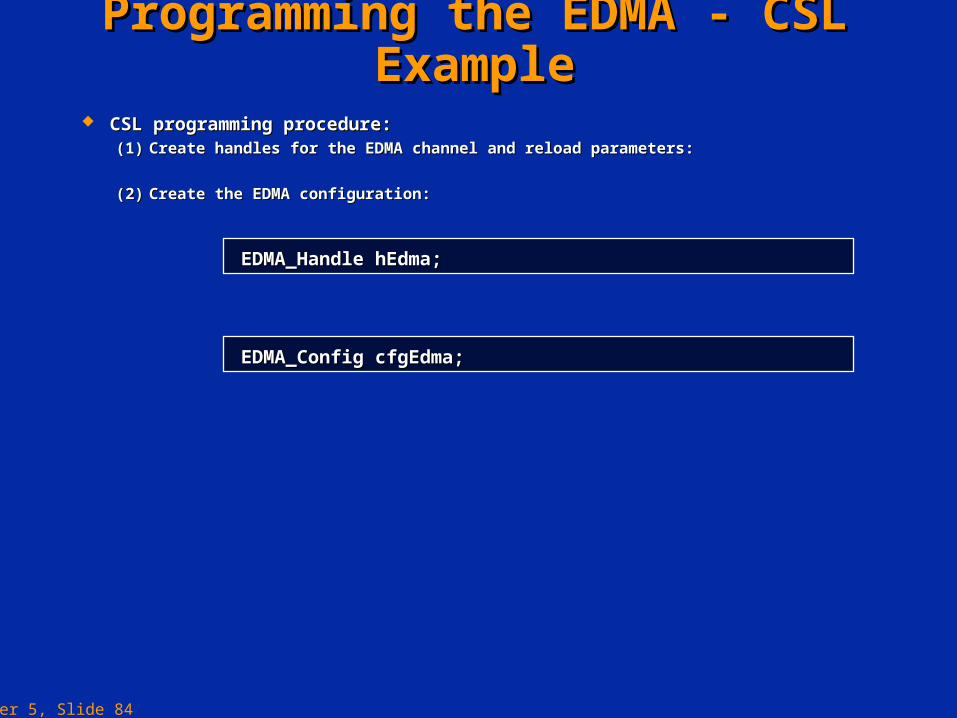
CSL programming procedure:CSL programming procedure:(1)(1) Create handles for the EDMA channel and reload parameters:Create handles for the EDMA channel and reload parameters:
(2)(2) Create the EDMA configuration:Create the EDMA configuration:
Programming the EDMA - CSL ExampleProgramming the EDMA - CSL Example
EDMA_Handle hEdma;EDMA_Handle hEdma;
EDMA_Config cfgEdma;EDMA_Config cfgEdma;
Chapter 5, Slide 85
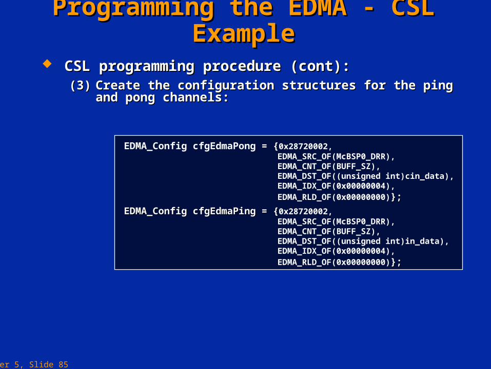
CSL programming procedure (cont):CSL programming procedure (cont):(3)(3) Create the configuration structures for the ping and pong Create the configuration structures for the ping and pong
channels:channels:
Programming the EDMA - CSL ExampleProgramming the EDMA - CSL Example
EDMA_Config cfgEdmaPong = {0x28720002, EDMA_SRC_OF(McBSP0_DRR), EDMA_CNT_OF(BUFF_SZ),
EDMA_DST_OF((unsigned int)cin_data),EDMA_IDX_OF(0x00000004),EDMA_RLD_OF(0x00000000)};};
EDMA_Config cfgEdmaPing = {EDMA_Config cfgEdmaPing = {0x28720002, EDMA_SRC_OF(McBSP0_DRR), EDMA_CNT_OF(BUFF_SZ),
EDMA_DST_OF((unsigned int)in_data),EDMA_IDX_OF(0x00000004),EDMA_RLD_OF(0x00000000)};};
Chapter 5, Slide 86
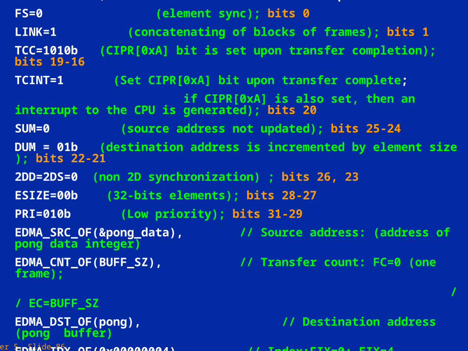
Pong Configuration : 0x403A0002, //Options
FS=0 (element sync); bits 0
LINK=1 (concatenating of blocks of frames); bits 1
TCC=1010b (CIPR[0xA] bit is set upon transfer completion); bits 19-16
TCINT=1 (Set CIPR[0xA] bit upon transfer complete;
if CIPR[0xA] is also set, then an interrupt to the CPU is generated); bits 20
SUM=0 (source address not updated); bits 25-24
DUM = 01b (destination address is incremented by element size ); bits 22-21
2DD=2DS=0 (non 2D synchronization) ; bits 26, 23
ESIZE=00b (32-bits elements); bits 28-27
PRI=010b (Low priority); bits 31-29
EDMA_SRC_OF(&pong_data), // Source address: (address of pong data integer)
EDMA_CNT_OF(BUFF_SZ), // Transfer count: FC=0 (one frame);
// EC=BUFF_SZ
EDMA_DST_OF(pong), // Destination address (pong buffer)
EDMA_IDX_OF(0x00000004), // Index:FIX=0; EIX=4
EDMA_RLD_OF(0x00000000) // Element count reload and link address
Chapter 5, Slide 87
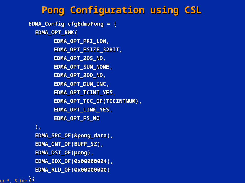
Pong Configuration using CSLPong Configuration using CSLEDMA_Config cfgEdmaPong = {EDMA_Config cfgEdmaPong = {
EDMA_OPT_RMK(EDMA_OPT_RMK(
EDMA_OPT_PRI_LOW,EDMA_OPT_PRI_LOW,
EDMA_OPT_ESIZE_32BIT,EDMA_OPT_ESIZE_32BIT,
EDMA_OPT_2DS_NO,EDMA_OPT_2DS_NO,
EDMA_OPT_SUM_NONE,EDMA_OPT_SUM_NONE,
EDMA_OPT_2DD_NO,EDMA_OPT_2DD_NO,
EDMA_OPT_DUM_INC,EDMA_OPT_DUM_INC,
EDMA_OPT_TCINT_YES,EDMA_OPT_TCINT_YES,
EDMA_OPT_TCC_OF(TCCINTNUM),EDMA_OPT_TCC_OF(TCCINTNUM),
EDMA_OPT_LINK_YES,EDMA_OPT_LINK_YES,
EDMA_OPT_FS_NOEDMA_OPT_FS_NO
),),
EDMA_SRC_OF(&pong_data),EDMA_SRC_OF(&pong_data),
EDMA_CNT_OF(BUFF_SZ),EDMA_CNT_OF(BUFF_SZ),
EDMA_DST_OF(pong),EDMA_DST_OF(pong),
EDMA_IDX_OF(0x00000004),EDMA_IDX_OF(0x00000004),
EDMA_RLD_OF(0x00000000)EDMA_RLD_OF(0x00000000)
}; };
Chapter 5, Slide 88
Programming the EDMA - CSL ExampleProgramming the EDMA - CSL Example
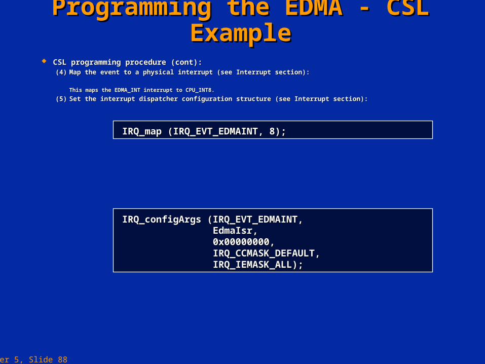
CSL programming procedure (cont):CSL programming procedure (cont):(4)(4) Map the event to a physical interrupt (see Interrupt section):Map the event to a physical interrupt (see Interrupt section):
This maps the EDMA_INT interrupt to CPU_INT8.This maps the EDMA_INT interrupt to CPU_INT8.
(5)(5) Set the interrupt dispatcher configuration structure (see Interrupt section):Set the interrupt dispatcher configuration structure (see Interrupt section):
IRQ_map (IRQ_EVT_EDMAINT, 8);IRQ_map (IRQ_EVT_EDMAINT, 8);
IRQ_configArgs (IRQ_EVT_EDMAINT,IRQ_configArgs (IRQ_EVT_EDMAINT, EdmaIsr,EdmaIsr, 0x00000000,0x00000000, IRQ_CCMASK_DEFAULT,IRQ_CCMASK_DEFAULT, IRQ_IEMASK_ALL);IRQ_IEMASK_ALL);
Chapter 5, Slide 89
Programming the EDMA - CSL ExampleProgramming the EDMA - CSL Example
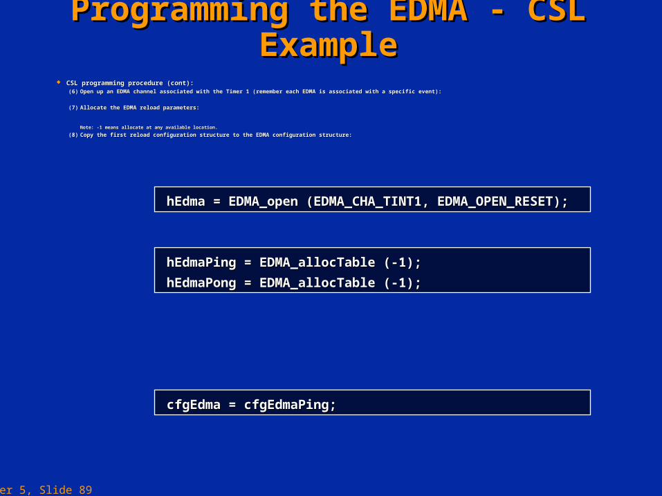
CSL programming procedure (cont):CSL programming procedure (cont):(6)(6) Open up an EDMA channel associated with the Timer 1 (remember each EDMA is associated with a specific event):Open up an EDMA channel associated with the Timer 1 (remember each EDMA is associated with a specific event):
(7)(7) Allocate the EDMA reload parameters:Allocate the EDMA reload parameters:
Note: -1 means allocate at any available location.Note: -1 means allocate at any available location.
(8)(8) Copy the first reload configuration structure to the EDMA configuration structure:Copy the first reload configuration structure to the EDMA configuration structure:
hEdmaPing = EDMA_allocTable (-1);hEdmaPing = EDMA_allocTable (-1);
hEdmaPong = EDMA_allocTable (-1);hEdmaPong = EDMA_allocTable (-1);
cfgEdma = cfgEdmaPing;cfgEdma = cfgEdmaPing;
hEdma = EDMA_open (EDMA_CHA_TINT1, EDMA_OPEN_RESET);hEdma = EDMA_open (EDMA_CHA_TINT1, EDMA_OPEN_RESET);
Chapter 5, Slide 90
Programming the EDMA - CSL ExampleProgramming the EDMA - CSL Example
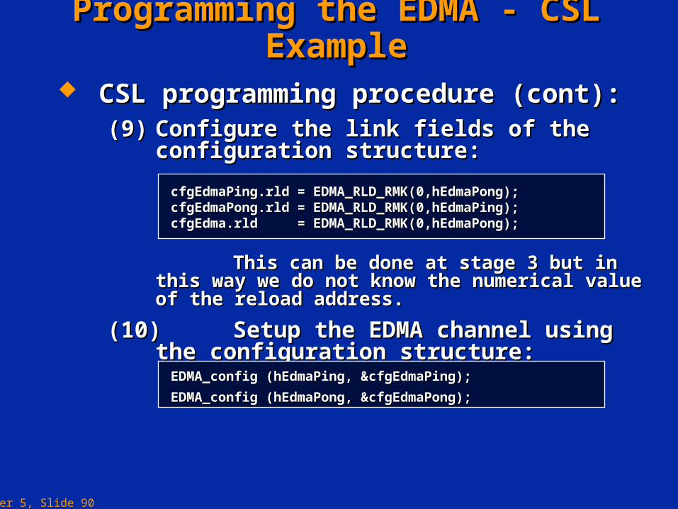
CSL programming procedure (cont):CSL programming procedure (cont):(9)(9) Configure the link fields of the configuration Configure the link fields of the configuration
structure:structure:
This can be done at stage 3 but in this way we do This can be done at stage 3 but in this way we do not know the numerical value of the reload address.not know the numerical value of the reload address.
(10)(10) Setup the EDMA channel using the configuration Setup the EDMA channel using the configuration structure:structure:
cfgEdmaPing.rld = EDMA_RLD_RMK(0,hEdmaPong);cfgEdmaPing.rld = EDMA_RLD_RMK(0,hEdmaPong);cfgEdmaPong.rld = EDMA_RLD_RMK(0,hEdmaPing);cfgEdmaPong.rld = EDMA_RLD_RMK(0,hEdmaPing);cfgEdma.rld = EDMA_RLD_RMK(0,hEdmaPong);cfgEdma.rld = EDMA_RLD_RMK(0,hEdmaPong);
EDMA_config (hEdmaPing, &cfgEdmaPing); EDMA_config (hEdmaPing, &cfgEdmaPing);
EDMA_config (hEdmaPong, &cfgEdmaPong);EDMA_config (hEdmaPong, &cfgEdmaPong);
Chapter 5, Slide 91
Programming the EDMA - CSL ExampleProgramming the EDMA - CSL Example
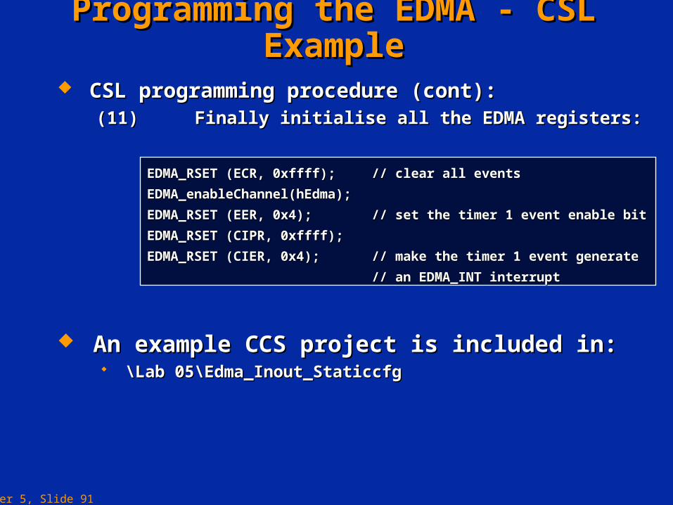
CSL programming procedure (cont):CSL programming procedure (cont):(11)(11) Finally initialise all the EDMA registers:Finally initialise all the EDMA registers:
EDMA_RSET (ECR, 0xffff);EDMA_RSET (ECR, 0xffff); // clear all events// clear all events
EDMA_enableChannel(hEdma);EDMA_enableChannel(hEdma);
EDMA_RSET (EER, 0x4);EDMA_RSET (EER, 0x4); // set the timer 1 event enable bit// set the timer 1 event enable bit
EDMA_RSET (CIPR, 0xffff);EDMA_RSET (CIPR, 0xffff);
EDMA_RSET (CIER, 0x4);EDMA_RSET (CIER, 0x4); // make the timer 1 event generate // make the timer 1 event generate
// an EDMA_INT interrupt// an EDMA_INT interrupt
An example CCS project is included in:An example CCS project is included in: \Lab 05\Edma_Inout_Staticcfg\Lab 05\Edma_Inout_Staticcfg
Chapter 5, Slide 92
Programming the EDMA - DSP/BIOS GUIProgramming the EDMA - DSP/BIOS GUI
(3)(3) DSP/BIOS GUI InterfaceDSP/BIOS GUI Interface With this method the configuration structure is created graphically With this method the configuration structure is created graphically
and the setup code is generated automatically.and the setup code is generated automatically.
Chapter 5, Slide 93
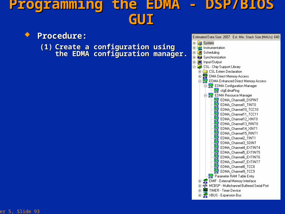
Procedure:Procedure:(1)(1) Create a configuration using the EDMA Create a configuration using the EDMA
configuration manager.configuration manager.
Programming the EDMA - DSP/BIOS GUIProgramming the EDMA - DSP/BIOS GUI
Chapter 5, Slide 94
Programming the EDMA - DSP/BIOS GUIProgramming the EDMA - DSP/BIOS GUI
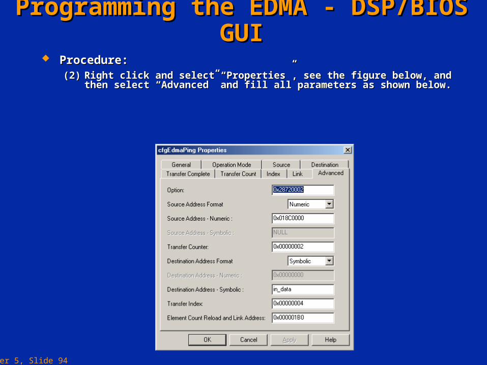
Procedure:Procedure:(2)(2) Right click and select “Properties”, see the figure below, and then Right click and select “Properties”, see the figure below, and then
select “Advanced” and fill all parameters as shown below.select “Advanced” and fill all parameters as shown below.
Chapter 5, Slide 95
Programming the EDMA - DSP/BIOS GUIProgramming the EDMA - DSP/BIOS GUI
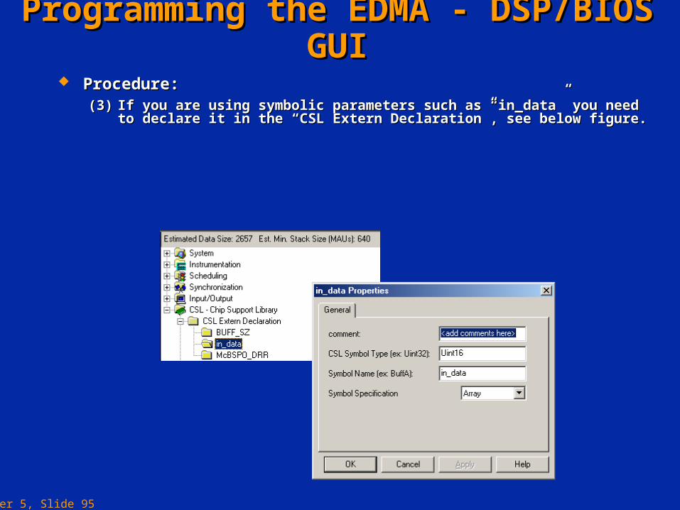
Procedure:Procedure:(3)(3) If you are using symbolic parameters such as “in_data” you need to If you are using symbolic parameters such as “in_data” you need to
declare it in the “CSL Extern Declaration”, see below figure.declare it in the “CSL Extern Declaration”, see below figure.
Chapter 5, Slide 96
Programming the EDMA - DSP/BIOS GUIProgramming the EDMA - DSP/BIOS GUI
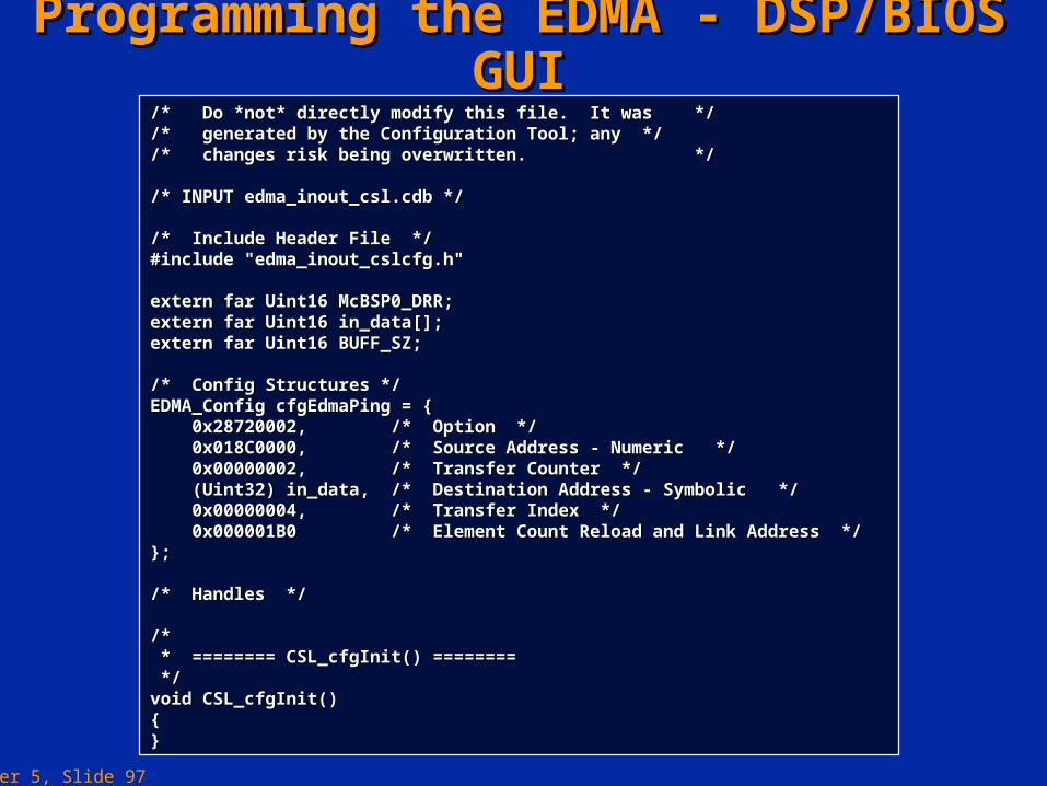
Procedure:Procedure:(4)(4) A file is then generated that contains the configuration code. The A file is then generated that contains the configuration code. The
file generated for this example is shown on the next slide.file generated for this example is shown on the next slide.
Chapter 5, Slide 97
Programming the EDMA - DSP/BIOS GUIProgramming the EDMA - DSP/BIOS GUI/* Do *not* directly modify this file. It was *//* Do *not* directly modify this file. It was *//* generated by the Configuration Tool; any *//* generated by the Configuration Tool; any *//* changes risk being overwritten. *//* changes risk being overwritten. */
/* INPUT edma_inout_csl.cdb *//* INPUT edma_inout_csl.cdb */
/* Include Header File *//* Include Header File */#include "edma_inout_cslcfg.h"#include "edma_inout_cslcfg.h"
extern far Uint16 McBSP0_DRR;extern far Uint16 McBSP0_DRR;extern far Uint16 in_data[];extern far Uint16 in_data[];extern far Uint16 BUFF_SZ;extern far Uint16 BUFF_SZ;
/* Config Structures *//* Config Structures */EDMA_Config cfgEdmaPing = {EDMA_Config cfgEdmaPing = { 0x28720002, /* Option */0x28720002, /* Option */ 0x018C0000, /* Source Address - Numeric */0x018C0000, /* Source Address - Numeric */ 0x00000002, /* Transfer Counter */0x00000002, /* Transfer Counter */ (Uint32) in_data, /* Destination Address - Symbolic */(Uint32) in_data, /* Destination Address - Symbolic */ 0x00000004, /* Transfer Index */0x00000004, /* Transfer Index */ 0x000001B0 /* Element Count Reload and Link Address */0x000001B0 /* Element Count Reload and Link Address */};};
/* Handles *//* Handles */
/*/* * ======== CSL_cfgInit() ======== * ======== CSL_cfgInit() ======== */*/void CSL_cfgInit()void CSL_cfgInit(){{}}
Chapter 5, Slide 98
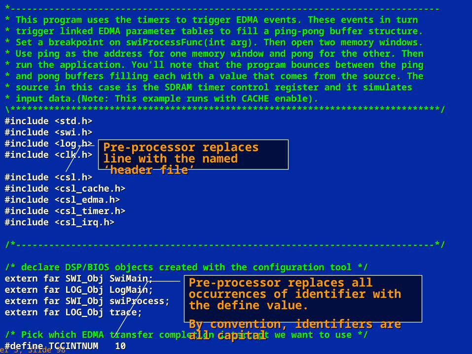
*------------------------------------------------------------------------------*------------------------------------------------------------------------------* This program uses the timers to trigger EDMA events. These events in turn * This program uses the timers to trigger EDMA events. These events in turn * trigger linked EDMA parameter tables to fill a ping-pong buffer structure. * trigger linked EDMA parameter tables to fill a ping-pong buffer structure. * Set a breakpoint on swiProcessFunc(int arg). Then open two memory windows. * Set a breakpoint on swiProcessFunc(int arg). Then open two memory windows. * Use ping as the address for one memory window and pong for the other. Then * Use ping as the address for one memory window and pong for the other. Then * run the application. You'll note that the program bounces between the ping * run the application. You'll note that the program bounces between the ping * and pong buffers filling each with a value that comes from the source. The * and pong buffers filling each with a value that comes from the source. The * source in this case is the SDRAM timer control register and it simulates * source in this case is the SDRAM timer control register and it simulates * input data.(Note: This example runs with CACHE enable). * input data.(Note: This example runs with CACHE enable). \******************************************************************************/\******************************************************************************/#include <std.h>#include <std.h>#include <swi.h>#include <swi.h>#include <log.h>#include <log.h>#include <clk.h>#include <clk.h>
#include <csl.h>#include <csl.h>#include <csl_cache.h>#include <csl_cache.h>#include <csl_edma.h>#include <csl_edma.h>#include <csl_timer.h>#include <csl_timer.h>#include <csl_irq.h>#include <csl_irq.h>
/*----------------------------------------------------------------------------*//*----------------------------------------------------------------------------*/
/* declare DSP/BIOS objects created with the configuration tool *//* declare DSP/BIOS objects created with the configuration tool */extern far SWI_Obj SwiMain;extern far SWI_Obj SwiMain;extern far LOG_Obj LogMain;extern far LOG_Obj LogMain;extern far SWI_Obj swiProcess;extern far SWI_Obj swiProcess;extern far LOG_Obj trace;extern far LOG_Obj trace;
/* Pick which EDMA transfer completion interrupt we want to use *//* Pick which EDMA transfer completion interrupt we want to use */#define TCCINTNUM 10#define TCCINTNUM 10
Pre-processor replaces all occurrences of Pre-processor replaces all occurrences of identifier with the define value.identifier with the define value.
By convention, identifiers are all capitalBy convention, identifiers are all capital
Pre-processor replaces line with the Pre-processor replaces line with the named ‘header file’named ‘header file’

Chapter 5, Slide 99
/* define some constants *//* define some constants */#define BUFF_SZ 256 /* ping-pong buffer sizes in # of ints */#define BUFF_SZ 256 /* ping-pong buffer sizes in # of ints */#define FCPU 150000000 /* CPU clock frequency */#define FCPU 150000000 /* CPU clock frequency */#define SRATE 8000 /* data sample rate (simulated w/timer */#define SRATE 8000 /* data sample rate (simulated w/timer */#define TPRD (FCPU/(4*SRATE)) /* timer period */#define TPRD (FCPU/(4*SRATE)) /* timer period */
/* Create the buffers. We want to align the buffers to be cache friendly *//* Create the buffers. We want to align the buffers to be cache friendly *//* by aligning them on an L2 cache line boundary. *//* by aligning them on an L2 cache line boundary. */#pragma DATA_ALIGN(ping,128);#pragma DATA_ALIGN(ping,128);#pragma DATA_ALIGN(pong,128);#pragma DATA_ALIGN(pong,128);#pragma DATA_ALIGN(outbuff,128);#pragma DATA_ALIGN(outbuff,128);int ping[BUFF_SZ];int ping[BUFF_SZ];int pong[BUFF_SZ];int pong[BUFF_SZ];int outbuff[BUFF_SZ];int outbuff[BUFF_SZ];
/* These two variables serve as the data sources for this example. *//* These two variables serve as the data sources for this example. *//* Also want to align these on a cache line boundary since they *//* Also want to align these on a cache line boundary since they *//* sources of EDMA transfers. *//* sources of EDMA transfers. */#pragma DATA_ALIGN(ping_data,128);#pragma DATA_ALIGN(ping_data,128);#pragma DATA_ALIGN(pong_data,128);#pragma DATA_ALIGN(pong_data,128);static int ping_data;static int ping_data;static int pong_data;static int pong_data;
/* global variable used to track the ping-pong'ing *//* global variable used to track the ping-pong'ing */static int pingpong = 0;static int pingpong = 0;
Assign an initial value to the variableAssign an initial value to the variable
An array of BUFF_SZ integers.An array of BUFF_SZ integers.
Indexed as pong[0], pong[1], …Indexed as pong[0], pong[1], …
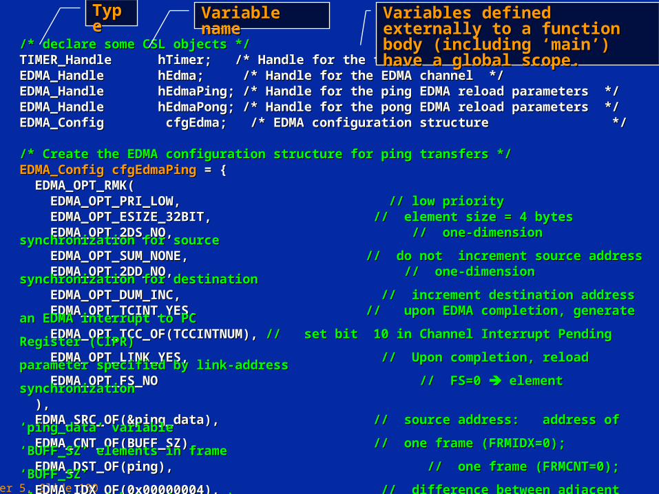
Chapter 5, Slide 100
/* declare some CSL objects *//* declare some CSL objects */TIMER_Handle hTimer; /* Handle for the timer device */TIMER_Handle hTimer; /* Handle for the timer device */EDMA_Handle hEdma; /* Handle for the EDMA channel */EDMA_Handle hEdma; /* Handle for the EDMA channel */EDMA_Handle hEdmaPing; /* Handle for the ping EDMA reload parameters */EDMA_Handle hEdmaPing; /* Handle for the ping EDMA reload parameters */EDMA_Handle hEdmaPong; /* Handle for the pong EDMA reload parameters */EDMA_Handle hEdmaPong; /* Handle for the pong EDMA reload parameters */EDMA_Config cfgEdma; /* EDMA configuration structure */EDMA_Config cfgEdma; /* EDMA configuration structure */
/* Create the EDMA configuration structure for ping transfers *//* Create the EDMA configuration structure for ping transfers */EDMA_Config cfgEdmaPingEDMA_Config cfgEdmaPing = { = { EDMA_OPT_RMK(EDMA_OPT_RMK( EDMA_OPT_PRI_LOW, EDMA_OPT_PRI_LOW, // low priority// low priority EDMA_OPT_ESIZE_32BIT, EDMA_OPT_ESIZE_32BIT, // element size = 4 bytes// element size = 4 bytes EDMA_OPT_2DS_NO, EDMA_OPT_2DS_NO, // one-dimension synchronization for source// one-dimension synchronization for source EDMA_OPT_SUM_NONE, EDMA_OPT_SUM_NONE, // do not increment source address// do not increment source address EDMA_OPT_2DD_NO, EDMA_OPT_2DD_NO, // one-dimension synchronization for destination// one-dimension synchronization for destination EDMA_OPT_DUM_INC, EDMA_OPT_DUM_INC, // increment destination address// increment destination address EDMA_OPT_TCINT_YES, EDMA_OPT_TCINT_YES, // upon EDMA completion, generate an EDMA interrupt to PC// upon EDMA completion, generate an EDMA interrupt to PC EDMA_OPT_TCC_OF(TCCINTNUM), EDMA_OPT_TCC_OF(TCCINTNUM), // set bit 10 in Channel Interrupt Pending Register (CIPR)// set bit 10 in Channel Interrupt Pending Register (CIPR) EDMA_OPT_LINK_YES, EDMA_OPT_LINK_YES, // Upon completion, reload parameter specified by link-address// Upon completion, reload parameter specified by link-address EDMA_OPT_FS_NO EDMA_OPT_FS_NO // FS=0 // FS=0 element synchronization element synchronization ),), EDMA_SRC_OF(&ping_data), EDMA_SRC_OF(&ping_data), // source address: address of ‘ping_data’ variable// source address: address of ‘ping_data’ variable EDMA_CNT_OF(BUFF_SZ), EDMA_CNT_OF(BUFF_SZ), // one frame (FRMIDX=0); ‘BUFF_SZ’ elements in frame// one frame (FRMIDX=0); ‘BUFF_SZ’ elements in frame EDMA_DST_OF(ping), EDMA_DST_OF(ping), // one frame (FRMCNT=0); ‘BUFF_SZ’// one frame (FRMCNT=0); ‘BUFF_SZ’ EDMA_IDX_OF(0x00000004), EDMA_IDX_OF(0x00000004), // difference between adjacent elements = 4 bytes (no gaps)// difference between adjacent elements = 4 bytes (no gaps) EDMA_RLD_OF(0x00000000) EDMA_RLD_OF(0x00000000) // to be defined later// to be defined later}; };
TypeType Variable nameVariable name Variables defined externally to a Variables defined externally to a function body (including ‘main’) have function body (including ‘main’) have a global scope.a global scope.
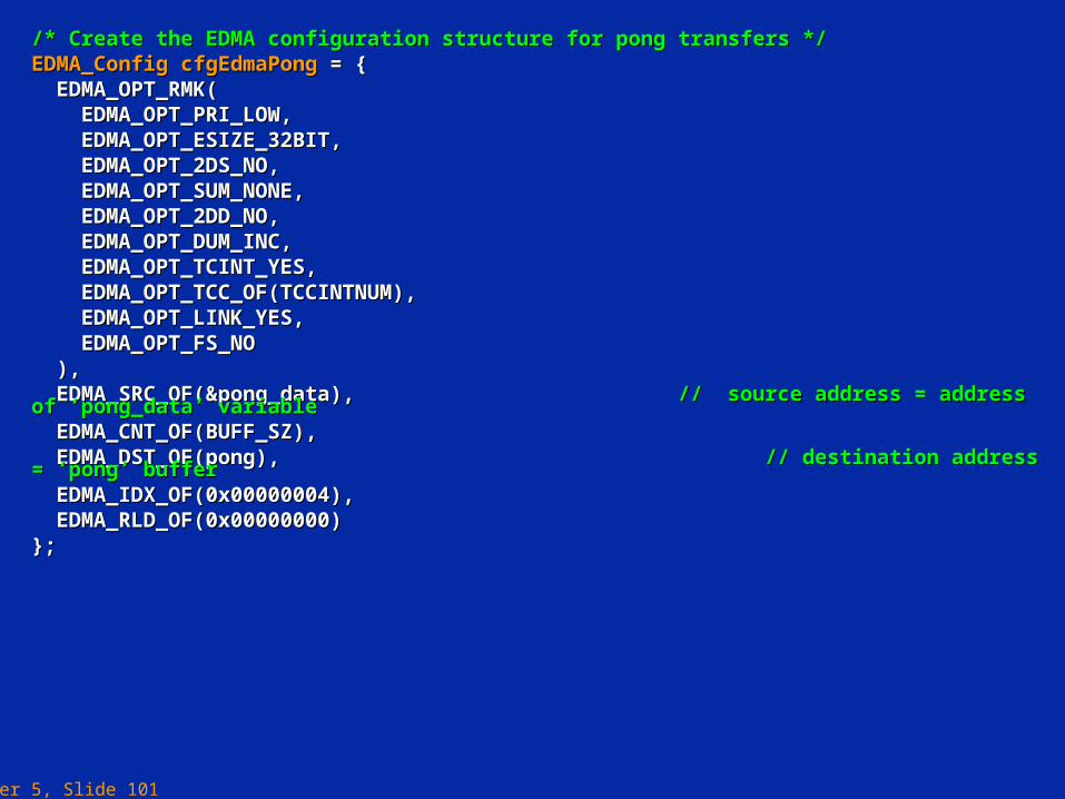
Chapter 5, Slide 101
/* Create the EDMA configuration structure for pong transfers *//* Create the EDMA configuration structure for pong transfers */EDMA_Config cfgEdmaPongEDMA_Config cfgEdmaPong = { = { EDMA_OPT_RMK(EDMA_OPT_RMK( EDMA_OPT_PRI_LOW,EDMA_OPT_PRI_LOW, EDMA_OPT_ESIZE_32BIT,EDMA_OPT_ESIZE_32BIT, EDMA_OPT_2DS_NO,EDMA_OPT_2DS_NO, EDMA_OPT_SUM_NONE,EDMA_OPT_SUM_NONE, EDMA_OPT_2DD_NO,EDMA_OPT_2DD_NO, EDMA_OPT_DUM_INC,EDMA_OPT_DUM_INC, EDMA_OPT_TCINT_YES,EDMA_OPT_TCINT_YES, EDMA_OPT_TCC_OF(TCCINTNUM),EDMA_OPT_TCC_OF(TCCINTNUM), EDMA_OPT_LINK_YES,EDMA_OPT_LINK_YES, EDMA_OPT_FS_NOEDMA_OPT_FS_NO ),), EDMA_SRC_OF(&pong_data), EDMA_SRC_OF(&pong_data), // source address = address of ‘pong_data’ variable// source address = address of ‘pong_data’ variable EDMA_CNT_OF(BUFF_SZ),EDMA_CNT_OF(BUFF_SZ), EDMA_DST_OF(pong), EDMA_DST_OF(pong), // destination address = ‘pong’ buffer// destination address = ‘pong’ buffer EDMA_IDX_OF(0x00000004),EDMA_IDX_OF(0x00000004), EDMA_RLD_OF(0x00000000)EDMA_RLD_OF(0x00000000)}; };
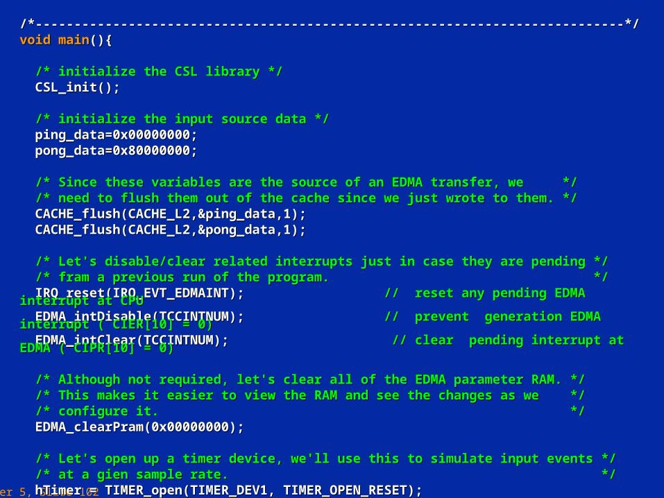
Chapter 5, Slide 102
/*----------------------------------------------------------------------------*//*----------------------------------------------------------------------------*/void mainvoid main(){(){
/* initialize the CSL library *//* initialize the CSL library */ CSL_init();CSL_init();
/* initialize the input source data *//* initialize the input source data */ ping_data=0x00000000;ping_data=0x00000000; pong_data=0x80000000;pong_data=0x80000000; /* Since these variables are the source of an EDMA transfer, we *//* Since these variables are the source of an EDMA transfer, we */ /* need to flush them out of the cache since we just wrote to them. *//* need to flush them out of the cache since we just wrote to them. */ CACHE_flush(CACHE_L2,&ping_data,1);CACHE_flush(CACHE_L2,&ping_data,1); CACHE_flush(CACHE_L2,&pong_data,1);CACHE_flush(CACHE_L2,&pong_data,1);
/* Let's disable/clear related interrupts just in case they are pending *//* Let's disable/clear related interrupts just in case they are pending */ /* fram a previous run of the program. */ /* fram a previous run of the program. */ IRQ_reset(IRQ_EVT_EDMAINT); IRQ_reset(IRQ_EVT_EDMAINT); // reset any pending EDMA interrupt at CPU// reset any pending EDMA interrupt at CPU EDMA_intDisable(TCCINTNUM); EDMA_intDisable(TCCINTNUM); // prevent generation EDMA interrupt ( CIER[10] = 0)// prevent generation EDMA interrupt ( CIER[10] = 0) EDMA_intClear(TCCINTNUM); EDMA_intClear(TCCINTNUM); // clear pending interrupt at EDMA ( CIPR[10] = 0)// clear pending interrupt at EDMA ( CIPR[10] = 0) /* Although not required, let's clear all of the EDMA parameter RAM. *//* Although not required, let's clear all of the EDMA parameter RAM. */ /* This makes it easier to view the RAM and see the changes as we *//* This makes it easier to view the RAM and see the changes as we */ /* configure it. *//* configure it. */ EDMA_clearPram(0x00000000);EDMA_clearPram(0x00000000); /* Let's open up a timer device, we'll use this to simulate input events *//* Let's open up a timer device, we'll use this to simulate input events */ /* at a gien sample rate. *//* at a gien sample rate. */ hTimer = TIMER_open(TIMER_DEV1, TIMER_OPEN_RESET);hTimer = TIMER_open(TIMER_DEV1, TIMER_OPEN_RESET);
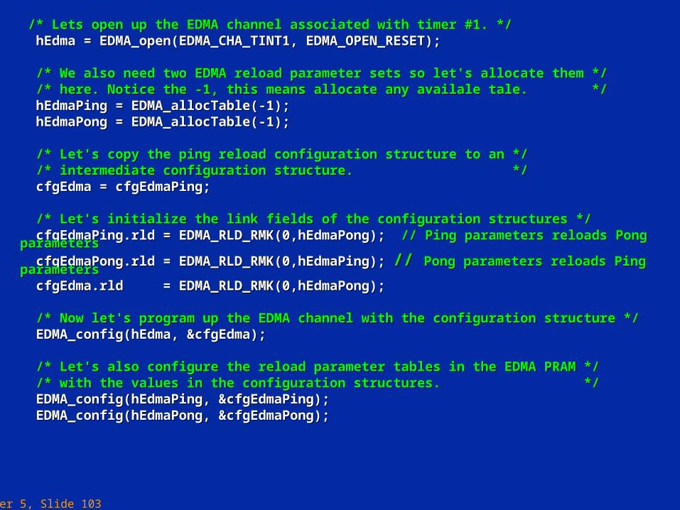
Chapter 5, Slide 103
/* Lets open up the EDMA channel associated with timer #1. *//* Lets open up the EDMA channel associated with timer #1. */ hEdma = EDMA_open(EDMA_CHA_TINT1, EDMA_OPEN_RESET);hEdma = EDMA_open(EDMA_CHA_TINT1, EDMA_OPEN_RESET);
/* We also need two EDMA reload parameter sets so let's allocate them *//* We also need two EDMA reload parameter sets so let's allocate them */ /* here. Notice the -1, this means allocate any availale tale. *//* here. Notice the -1, this means allocate any availale tale. */ hEdmaPing = EDMA_allocTable(-1);hEdmaPing = EDMA_allocTable(-1); hEdmaPong = EDMA_allocTable(-1);hEdmaPong = EDMA_allocTable(-1);
/* Let's copy the ping reload configuration structure to an *//* Let's copy the ping reload configuration structure to an */ /* intermediate configuration structure. *//* intermediate configuration structure. */ cfgEdma = cfgEdmaPing;cfgEdma = cfgEdmaPing; /* Let's initialize the link fields of the configuration structures *//* Let's initialize the link fields of the configuration structures */ cfgEdmaPing.rld = EDMA_RLD_RMK(0,hEdmaPong); cfgEdmaPing.rld = EDMA_RLD_RMK(0,hEdmaPong); // Ping parameters reloads Pong parameters// Ping parameters reloads Pong parameters
cfgEdmaPong.rld = EDMA_RLD_RMK(0,hEdmaPing); cfgEdmaPong.rld = EDMA_RLD_RMK(0,hEdmaPing); // // Pong parameters reloads Ping parametersPong parameters reloads Ping parameters cfgEdma.rld = EDMA_RLD_RMK(0,hEdmaPong);cfgEdma.rld = EDMA_RLD_RMK(0,hEdmaPong);
/* Now let's program up the EDMA channel with the configuration structure *//* Now let's program up the EDMA channel with the configuration structure */ EDMA_config(hEdma, &cfgEdma); EDMA_config(hEdma, &cfgEdma); /* Let's also configure the reload parameter tables in the EDMA PRAM *//* Let's also configure the reload parameter tables in the EDMA PRAM */ /* with the values in the configuration structures. *//* with the values in the configuration structures. */ EDMA_config(hEdmaPing, &cfgEdmaPing);EDMA_config(hEdmaPing, &cfgEdmaPing); EDMA_config(hEdmaPong, &cfgEdmaPong); EDMA_config(hEdmaPong, &cfgEdmaPong);

Chapter 5, Slide 104
/* Configure up the timer. *//* Configure up the timer. */ TIMER_configArgs(hTimer, TIMER_configArgs(hTimer, TIMER_CTL_OF(0x00000200), TIMER_CTL_OF(0x00000200), TIMER_PRD_OF(TPRD), TIMER_PRD_OF(TPRD), TIMER_CNT_OF(0)TIMER_CNT_OF(0) ); );
/* Enable the related interrupts *//* Enable the related interrupts */ IRQ_enable(IRQ_EVT_EDMAINT); IRQ_enable(IRQ_EVT_EDMAINT); // enable EDMA interrupt at CPU// enable EDMA interrupt at CPU EDMA_intEnable(TCCINTNUM); EDMA_intEnable(TCCINTNUM); // enable generating interrupt at EDMA (CEIR[10] = 1)// enable generating interrupt at EDMA (CEIR[10] = 1) /* Enable the EDMA channel *//* Enable the EDMA channel */ EDMA_enableChannel(hEdma); EDMA_enableChannel(hEdma); // enable EDMA channel 2 (associated with Timer 1) EER[2] =1// enable EDMA channel 2 (associated with Timer 1) EER[2] =1 /* Finally, enable the timer which will drive everything. *//* Finally, enable the timer which will drive everything. */ TIMER_start(hTimer);TIMER_start(hTimer);}}
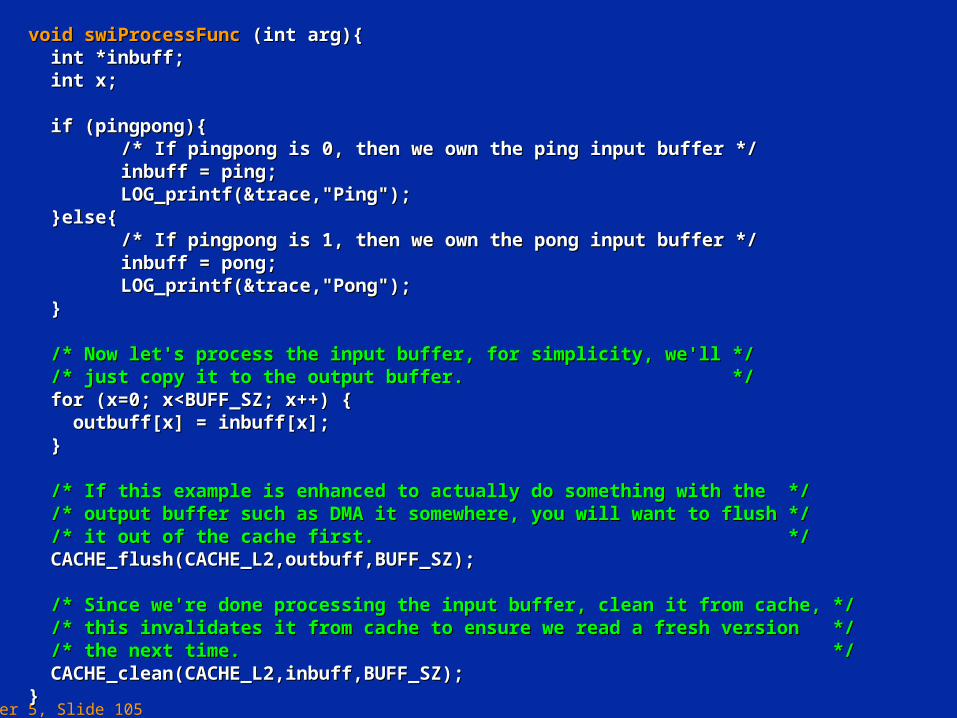
Chapter 5, Slide 105
void swiProcessFunc void swiProcessFunc (int arg){(int arg){ int *inbuff;int *inbuff; int x;int x;
if (pingpong){if (pingpong){ /* If pingpong is 0, then we own the ping input buffer *//* If pingpong is 0, then we own the ping input buffer */ inbuff = ping;inbuff = ping; LOG_printf(&trace,"Ping"); LOG_printf(&trace,"Ping");
}else{}else{ /* If pingpong is 1, then we own the pong input buffer *//* If pingpong is 1, then we own the pong input buffer */ inbuff = pong;inbuff = pong; LOG_printf(&trace,"Pong");LOG_printf(&trace,"Pong");
} }
/* Now let's process the input buffer, for simplicity, we'll *//* Now let's process the input buffer, for simplicity, we'll */ /* just copy it to the output buffer. *//* just copy it to the output buffer. */ for (x=0; x<BUFF_SZ; x++) {for (x=0; x<BUFF_SZ; x++) { outbuff[x] = inbuff[x];outbuff[x] = inbuff[x]; }}
/* If this example is enhanced to actually do something with the *//* If this example is enhanced to actually do something with the */ /* output buffer such as DMA it somewhere, you will want to flush *//* output buffer such as DMA it somewhere, you will want to flush */ /* it out of the cache first. *//* it out of the cache first. */ CACHE_flush(CACHE_L2,outbuff,BUFF_SZ);CACHE_flush(CACHE_L2,outbuff,BUFF_SZ); /* Since we're done processing the input buffer, clean it from cache, *//* Since we're done processing the input buffer, clean it from cache, */ /* this invalidates it from cache to ensure we read a fresh version *//* this invalidates it from cache to ensure we read a fresh version */ /* the next time. *//* the next time. */ CACHE_clean(CACHE_L2,inbuff,BUFF_SZ);CACHE_clean(CACHE_L2,inbuff,BUFF_SZ);}}
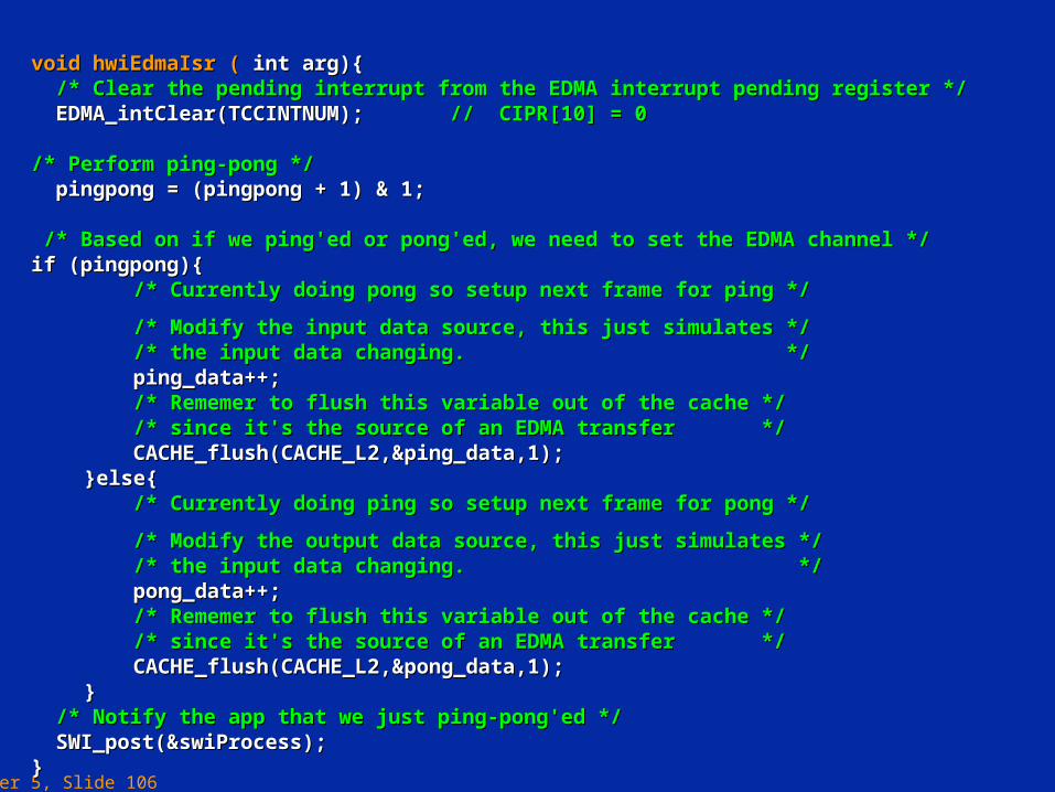
Chapter 5, Slide 106
voidvoid hwiEdmaIsr ( hwiEdmaIsr ( int arg){ int arg){ /* Clear the pending interrupt from the EDMA interrupt pending register *//* Clear the pending interrupt from the EDMA interrupt pending register */ EDMA_intClear(TCCINTNUM); EDMA_intClear(TCCINTNUM); // CIPR[10] = 0// CIPR[10] = 0 /* Perform ping-pong *//* Perform ping-pong */ pingpong = (pingpong + 1) & 1;pingpong = (pingpong + 1) & 1; /* Based on if we ping'ed or pong'ed, we need to set the EDMA channel *//* Based on if we ping'ed or pong'ed, we need to set the EDMA channel */if (pingpong){if (pingpong){
/* Currently doing pong so setup next frame for ping */ /* Currently doing pong so setup next frame for ping */ /* Modify the input data source, this just simulates *//* Modify the input data source, this just simulates */ /* the input data changing. *//* the input data changing. */ ping_data++;ping_data++; /* Rememer to flush this variable out of the cache *//* Rememer to flush this variable out of the cache */ /* since it's the source of an EDMA transfer *//* since it's the source of an EDMA transfer */ CACHE_flush(CACHE_L2,&ping_data,1); CACHE_flush(CACHE_L2,&ping_data,1); }else{}else{ /* Currently doing ping so setup next frame for pong */ /* Currently doing ping so setup next frame for pong */ /* Modify the output data source, this just simulates *//* Modify the output data source, this just simulates */ /* the input data changing. *//* the input data changing. */ pong_data++;pong_data++; /* Rememer to flush this variable out of the cache *//* Rememer to flush this variable out of the cache */ /* since it's the source of an EDMA transfer *//* since it's the source of an EDMA transfer */ CACHE_flush(CACHE_L2,&pong_data,1);CACHE_flush(CACHE_L2,&pong_data,1);} }
/* Notify the app that we just ping-pong'ed *//* Notify the app that we just ping-pong'ed */ SWI_post(&swiProcess);SWI_post(&swiProcess);}}
Chapter 5Chapter 5
Enhanced Direct Memory Access Enhanced Direct Memory Access (EDMA)(EDMA)
- End -- End -