Chapter 5 - Dr. Javier Ortegaortagaja-utpa.weebly.com/uploads/2/6/0/1/26013343/chapter_5_dr... ·...
45
Chapter 5 The Second Law of Thermodynamics
Transcript of Chapter 5 - Dr. Javier Ortegaortagaja-utpa.weebly.com/uploads/2/6/0/1/26013343/chapter_5_dr... ·...

Chapter 5
The Second Law of
Thermodynamics
Learning Outcomes
►Demonstrate understanding of key concepts
related to the second law of thermodynamics,
including
►alternative statements of the second law,
►the internally reversible process, and
►the Kelvin temperature scale.
►List several important irreversibilities.

Learning Outcomes, cont.
►Assess the performance of power cycles
and refrigeration and heat pump cycles
►Describe the Carnot cycle.
►Interpret the Clausius inequality as
expressed by Eq. 5.13.

Aspects of the
Second Law of Thermodynamics
►From conservation of mass and energy
principles, mass and energy cannot be
created or destroyed.
►For a process, conservation of mass and
energy principles indicate the disposition of
mass and energy but do not infer whether the
process can actually occur.
►The second law of thermodynamics
provides the guiding principle for whether a
process can occur.
Aspects of the
Second Law of Thermodynamics
►predicting the direction of processes.
►establishing conditions for equilibrium.
►determining the best theoretical performance of cycles, engines, and other devices.
►evaluating quantitatively the factors that preclude attainment of the best theoretical performance level.
The second law of thermodynamics has many
aspects, which at first may appear different in kind
from those of conservation of mass and energy
principles. Among these aspects are:

Aspects of the
Second Law of Thermodynamics
►defining a temperature scale independent of the
properties of any thermometric substance.
►developing means for evaluating properties
such as u and h in terms of properties that are
more readily obtained experimentally.
Other aspects of the second law include:

Second Law of Thermodynamics
Alternative Statements
►Clausius Statement
►Kelvin-Planck Statement
►Entropy Statement
There is no simple statement that captures all
aspects of the second law. Several
alternative formulations of the second law are
found in the technical literature. Three
prominent ones are:
Second Law of Thermodynamics
Alternative Statements
►The focus of Chapter 5 is on the Clausius and
Kelvin-Planck statements.
►The Entropy statement is developed and applied
in Chapter 6.
►Like every physical law, the basis of the second
law of thermodynamics is experimental
evidence.

Clausius Statement
of the Second Law
It is impossible for any system to operate in such
a way that the sole result would be an energy
transfer by heat from a cooler to a hotter body.
Rudolf Clausius
(1822 –1888)

Thermal Reservoir
►A thermal reservoir is a system that
always remains at constant temperature
even though energy is added or removed
by heat transfer.
►Such a system is approximated by the
earth’s atmosphere, lakes and oceans, and
a large block of a solid such as copper.

Kelvin-Planck Statement
of the Second Law
It is impossible for any system to operate in a
thermodynamic cycle and deliver a net amount
of energy by work to its surroundings while
receiving energy by heat transfer from a single
thermal reservoir.
Max Planck
(1858 –1947)
Lord Kelvin
([K] = [°C] + 273.15)

Entropy Statement
of the Second Law
►Mass and energy are familiar examples of
extensive properties used in thermodynamics.
►Entropy is another important extensive property.
How entropy is evaluated and applied is detailed
in Chapter 6.
►Unlike mass and energy, which are conserved,
entropy is produced within systems whenever
non-idealities such as friction are present.
►The Entropy Statement is:
It is impossible for any system to operate in
a way that entropy is destroyed.

What is Entropy?? • The thermodynamic definition was developed in the early 1850s
by Rudolf Clausius and essentially describes how to measure the
entropy of an isolated system in thermodynamic equilibrium.
• Clausius created the term entropy in 1865 as an extensive
thermodynamic variable was shown to be useful in characterizing
the Carnot cycle.
• Heat transfer along the isotherm steps of the Carnot cycle was
found to be proportional to the temperature of a system (known as
its absolute temperature).
• This relationship was expressed in increments of entropy equal to
the ratio of incremental heat transfer divided by temperature, which
was found to vary in the thermodynamic cycle but eventually return
to the same value at the end of every cycle.
• Clausius wrote that he "intentionally formed the word Entropy as
similar as possible to the word Energy", basing the term on the
Greek ἡ τροπή [tropé],transformation.

Irreversibilities
►One of the important uses of the second law of
thermodynamics in engineering is to determine
the best theoretical performance of systems.
►By comparing actual performance with best
theoretical performance, insights often can be had
about the potential for improved performance.
►Best theoretical performance is evaluated in terms
of idealized processes.
►Actual processes are distinguishable from such
idealized processes by the presence of non-
idealities – called irreversibilities.

Irreversibilities Commonly
Encountered in Engineering Practice
►Heat transfer through a finite temperature
difference
►Unrestrained expansion of a gas or liquid to a lower
pressure
►Spontaneous chemical reaction
►Spontaneous mixing of matter at different
compositions or states
►Friction – sliding friction as well as friction in the
flow of fluids

Irreversibilities Commonly
Encountered in Engineering Practice
►Electric current flow through a resistance
►Magnetization or polarization with hysteresis
►Inelastic deformation
All actual processes involve effects such as
those listed, including naturally occurring
processes and ones involving devices we
construct – from the simplest mechanisms to
the largest industrial plants.

Irreversible and Reversible
Processes
►within the system, or
►within its surroundings (usually the
immediate surroundings), or
►within both the system and its
surroundings.
During a process of a system,
irreversibilities may be present:

Irreversible and Reversible
Processes
►A process is irreversible when
irreversibilities are present within the system
and/or its surroundings.
All actual processes are irreversible.
►A process is reversible when no
irreversibilities are present within the system
and its surroundings.
This type of process is fully idealized.
Irreversible and Reversible
Processes
►A process is internally reversible when no
irreversibilities are present within the
system. Irreversibilities may be present
within the surroundings, however.

Example: Internally Reversible Process
Water contained within a piston-cylinder evaporates
from saturated liquid to saturated vapor at 100oC. As
the water evaporates, it passes through a sequence of
equilibrium states while there is heat transfer to the
water from hot gases at 500oC.
►Such spontaneous
heat transfer is an
irreversibility in its
surroundings: an
external irreversibility.
►For a system enclosing the water there are no
internal irreversibilities, but

Analytical Form of the
Kelvin-Planck Statement
For any system undergoing a
thermodynamic cycle while
exchanging energy by heat
transfer with a single thermal
reservoir, the net work, Wcycle,
can be only negative or zero –
never positive:
Wcycle ≤ 0 < 0: Internal irreversibilities present
= 0: No internal irreversibilities single
reservoir
(Eq. 5.3)
NO!

Applications to Power Cycles Interacting
with Two Thermal Reservoirs
For a system undergoing a power cycle while
communicating thermally with two thermal
reservoirs, a hot reservoir and a cold reservoir,
(Eq. 5.4)
H
C
H
cycle1
Q
Q
Q
W
the thermal efficiency of any such cycle is

Applications to Power Cycles Interacting
with Two Thermal Reservoirs
By applying the Kelvin-Planck statement of the
second law, Eq. 5.3, three conclusions can be drawn:
1. The value of the thermal efficiency must be less
than 100%. Only a portion of the heat transfer QH
can be obtained as work and the remainder QC is
discharged by heat transfer to the cold reservoir.
Two other conclusions, called the Carnot corollaries,
are:
Carnot Corollaries
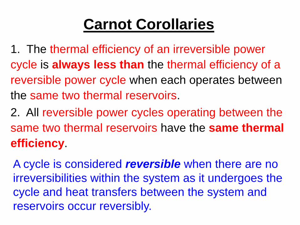
1. The thermal efficiency of an irreversible power
cycle is always less than the thermal efficiency of a
reversible power cycle when each operates between
the same two thermal reservoirs.
A cycle is considered reversible when there are no
irreversibilities within the system as it undergoes the
cycle and heat transfers between the system and
reservoirs occur reversibly.
2. All reversible power cycles operating between the
same two thermal reservoirs have the same thermal
efficiency.
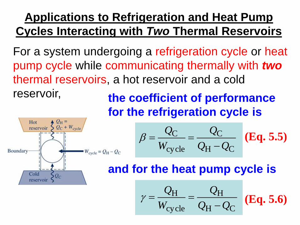
Applications to Refrigeration and Heat Pump
Cycles Interacting with Two Thermal Reservoirs
For a system undergoing a refrigeration cycle or heat
pump cycle while communicating thermally with two
thermal reservoirs, a hot reservoir and a cold
reservoir,
(Eq. 5.5) CH
C
cycle
C
Q
W
Q
the coefficient of performance
for the refrigeration cycle is
(Eq. 5.6) CH
H
cycle
H
Q
W
Q
and for the heat pump cycle is

Applications to Refrigeration and Heat Pump Cycles
Interacting with Two Thermal Reservoirs
By applying the Kelvin-Planck statement of the
second law, Eq. 5.3, three conclusions can be drawn:
1. For a refrigeration effect to occur a net work input
Wcycle is required. Accordingly, the coefficient of
performance must be finite in value.
Two other conclusions are:

Applications to Refrigeration and Heat Pump Cycles
Interacting with Two Thermal Reservoirs
1. The coefficient of performance of an irreversible
refrigeration cycle is always less than the coefficient
of performance of a reversible refrigeration cycle
when each operates between the same two thermal
reservoirs.
All three conclusions also apply to a system
undergoing a heat pump cycle between hot and cold
reservoirs.
2. All reversible refrigeration cycles operating
between the same two thermal reservoirs have the
same coefficient of performance.
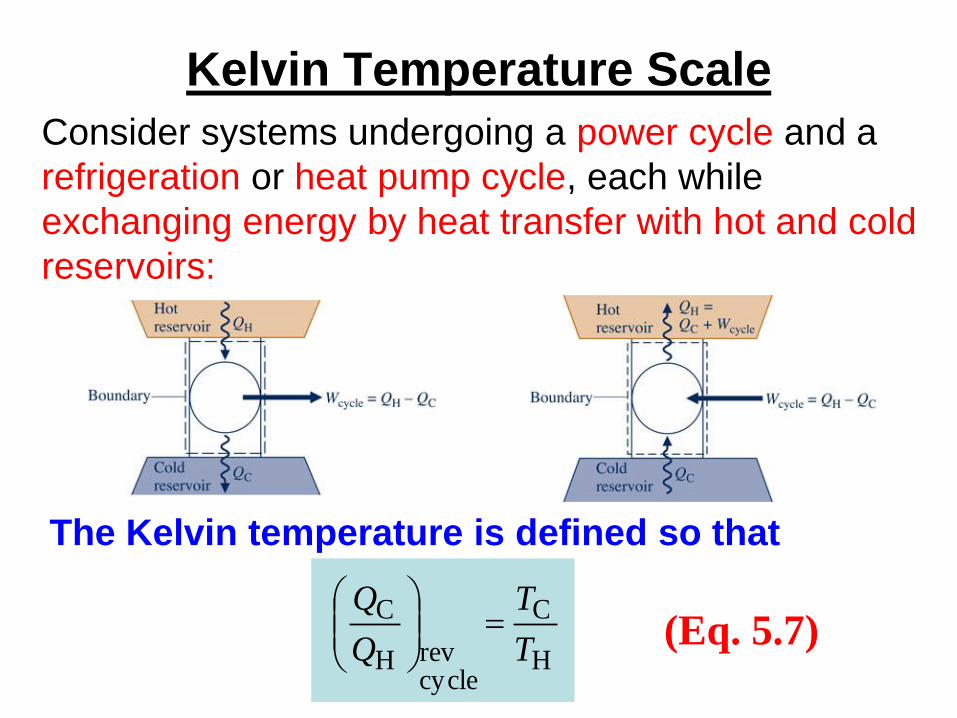
Kelvin Temperature Scale
Consider systems undergoing a power cycle and a
refrigeration or heat pump cycle, each while
exchanging energy by heat transfer with hot and cold
reservoirs:
(Eq. 5.7) H
C
cyclerevH
C
T
T
Q
Q
The Kelvin temperature is defined so that


Kelvin Temperature Scale
►In words, Eq. 5.7 states: When cycles are reversible, and only then, the ratio of the heat transfers equals a ratio of temperatures on the Kelvin scale, where TH is the temperature of the hot reservoir and TC is the temperature of the hot reservoir.
►As temperatures on the Rankine scale differ from
Kelvin temperatures only by the factor 1.8:
T(oR)=1.8T(K), the T’s in Eq. 5.7 may be on either
scale of temperature. Equation 5.7 is not valid for
temperatures in oC or oF, for these do not differ from
Kelvin temperatures by only a factor:
T(oC) = T(K) – 273.15
T(oF) = T(R) – 459.67

Maximum Performance Measures for Cycles
Operating between Two Thermal Reservoirs
1. The thermal efficiency of an irreversible power cycle is
always less than the thermal efficiency of a reversible power
cycle when each operates between the same two thermal
reservoirs.
Previous deductions from the Kelvin-Planck statement of the
second law include:
2. The coefficient of performance of an irreversible
refrigeration cycle is always less than the coefficient of
performance of a reversible refrigeration cycle when each
operates between the same two thermal reservoirs.
3. The coefficient of performance of an irreversible heat pump
cycle is always less than the coefficient of performance of a
reversible heat pump cycle when each operates between the
same two thermal reservoirs.

Maximum Performance Measures for Cycles
Operating between Two Thermal Reservoirs
It follows that the maximum theoretical thermal efficiency and
coefficients of performance in these cases are achieved only
by reversible cycles. Using Eq. 5.7 in Eqs. 5.4, 5.5, and 5.6,
we get respectively:
(Eq. 5.9) H
Cmax 1
T
TPower Cycle:
(Eq. 5.10) CH
Cmax
TT
T
Refrigeration Cycle:
(Eq. 5.11) CH
Hmax
TT
T
Heat Pump Cycle:
where TH and TC must be on the Kelvin or Rankine scale.

Example: Power Cycle Analysis
A system undergoes a power cycle while
receiving 1000 kJ by heat transfer from a
thermal reservoir at a temperature of 500 K
and discharging 600 kJ by heat transfer to a
thermal reservoir at (a) 200 K, (b) 300 K, (c)
400 K. For each case, determine whether
the cycle operates irreversibly, operates
reversibly, or is impossible.
Solution: To determine the nature of the cycle, compare
actual cycle performance () to maximum theoretical cycle
performance (max) calculated from Eq. 5.9
Power
Cycle
Wcycle
Hot Reservoir
TH = 500 K
Cold Reservoir
TC = (a) 200 K,
(b) 300 K,
(c) 400 K
QC = 600 kJ
QH = 1000 kJ
Power
Cycle
Wcycle
Hot Reservoir
TH = 500 K
Cold Reservoir
TC = (a) 200 K,
(b) 300 K,
(c) 400 K
QC = 600 kJ
QH = 1000 kJ

Example: Power Cycle Analysis
4.0kJ 1000
kJ 60011
H
C Q
Q
Actual Performance: Calculate using the heat
transfers:
Maximum Theoretical Performance: Calculate
max from Eq. 5.9 and compare to :
(a) 6.0K 500
K 20011
H
Cmax
T
T
(b) 4.0K 500
K 30011
H
Cmax
T
T
(c) 2.0K 500
K 40011
H
Cmax
T
T
Reversibly 0.4 = 0.4
Impossible 0.4 > 0.2
Irreversibly 0.4 < 0.6
max
Carnot Cycle
►The Carnot cycle provides a specific example of a reversible cycle that operates between two thermal reservoirs. Other examples are provided in Chapter 9: the Ericsson and Stirling cycles.
►In a Carnot cycle, the system executing the cycle undergoes a series of four internally reversible processes: two adiabatic processes alternated with two isothermal processes.

Carnot Power Cycles
The p-v diagram and schematic of a gas in a piston-cylinder
assembly executing a Carnot cycle are shown below:

Carnot Power Cycles The p-v diagram and schematic of water executing a Carnot
cycle through four interconnected components are shown
below:
In each of these cases the thermal efficiency is given by
(Eq. 5.9) H
Cmax 1
T
T

Carnot Refrigeration and Heat Pump Cycles
►If a Carnot power cycle is operated in the opposite
direction, the magnitudes of all energy transfers
remain the same but the energy transfers are
oppositely directed.
►Such a cycle may be regarded as a Carnot
refrigeration or heat pump cycle for which the
coefficient of performance is given, respectively, by
(Eq. 5.10) CH
Cmax
TT
T
Carnot Refrigeration Cycle:
(Eq. 5.11) CH
Hmax
TT
T
Carnot Heat Pump Cycle:

Clausius Inequality
►The Clausius inequality considered next provides the basis for developing the entropy concept in Chapter 6.
►The Clausius inequality is applicable to any cycle without regard for the body, or bodies, from which the system undergoing a cycle receives energy by heat transfer or to which the system rejects energy by heat transfer. Such bodies need not be thermal reservoirs.

Clausius Inequality
►The Clausius inequality is developed from
the Kelvin-Planck statement of the second
law and can be expressed as:
cycleb
T
Q(Eq. 5.13)
where
indicates integral is to be performed over all parts of the
boundary and over the entire cycle.
subscript indicates integrand is evaluated at the boundary
of the system executing the cycle.
b

Clausius Inequality
►The Clausius inequality is developed from
the Kelvin-Planck statement of the second
law and can be expressed as:
cycleb
T
Q(Eq. 5.13)
The nature of the cycle executed is indicated by the value
of cycle:
cycle = 0 no irreversibilities present within the system
cycle > 0 irreversibilities present within the system
cycle < 0 impossible
Eq.
5.14

Example: Use of Clausius Inequality
A system undergoes a cycle while receiving
1000 kJ by heat transfer at a temperature of 500 K
and discharging 600 kJ by heat transfer at (a) 200
K, (b) 300 K, (c) 400 K. Using Eqs. 5.13 and 5.14,
what is the nature of the cycle in each of these
cases?
Solution: To determine the nature of the cycle,
perform the cyclic integral of Eq. 5.13 to each case
and apply Eq. 5.14 to draw a conclusion about the
nature of each cycle.

Example: Use of Clausius Inequality
Applying Eq. 5.13 to each cycle: cycleC
out
H
in T
Q
T
Q
b
T
Q
(b) kJ/K 0K 300
kJ 600
K 500
kJ 1000cycle cycle = 0 kJ/K = 0
(a) kJ/K 1K 200
kJ 600
K 500
kJ 1000cycle cycle = +1 kJ/K > 0
Irreversibilities present within system
No irreversibilities present within system
(c) kJ/K 5.0K 400
kJ 600
K 500
kJ 1000cycle cycle = –0.5 kJ/K < 0
Impossible