Chapter 4 Spacecraft Interfaces Table of Contents€¦ · Chapter 4 Spacecraft Interfaces Table of...
32
Rockot User's Guide, EHB0003, Issue 5, Revision 0, August 2011 4-i Chapter 4 Spacecraft Interfaces Table of Contents 4 Spacecraft Interfaces.....................................................................................................4-1 4.1 Mechanical Interfaces ..........................................................................................4-1 4.1.1 Payload Accommodation ..........................................................................4-1 4.1.2 Usable Volume for Payload ......................................................................4-3 4.1.3 Spacecraft Accessibility ............................................................................4-3 4.1.4 Separation Systems..................................................................................4-3 4.1.4.1 Clamp Band Separation Systems.............................................4-5 4.1.4.2 Mechanical Lock Systems ........................................................4-9 4.1.4.3 Minisatellite Separation System .............................................4-10 4.1.5 Payload Adapters ...................................................................................4-12 4.1.5.1 Clamp Band Separation System Adapters .............................4-12 4.1.5.2 Mechanical Lock System Payload Adapters ..........................4-17 4.2 Electrical Interfaces ............................................................................................4-20 4.2.1 On-board Interfaces ................................................................................4-20 4.2.1.1 Umbilical Connectors..............................................................4-20 4.2.1.2 Separation Verification ...........................................................4-20 4.2.1.3 Interface Electrical Constraints ...............................................4-20 4.2.1.4 Umbilical Harness Configuration and Specifications ..............4-22 4.2.1.5 Matchmate / Electrical Checkout ............................................4-24 4.2.1.6 Spacecraft Electrical Interface Input Data Requirements .......4-24 4.2.2 Ground Electrical Interface .....................................................................4-24 4.2.3 Payload Grounding and Bonding ............................................................4-26 4.2.4 Payload Auxiliary Power Supply .............................................................4-28 4.2.4.1 Ground Auxiliary Power Supply ..............................................4-28 4.2.4.2 In-flight Power Supply.............................................................4-28 4.2.4.3 Optional Services ...................................................................4-28 4.2.5 Separation Ignition Command ................................................................4-28 4.2.6 Payload Telemetry Support ....................................................................4-28
Transcript of Chapter 4 Spacecraft Interfaces Table of Contents€¦ · Chapter 4 Spacecraft Interfaces Table of...
Rockot User's Guide, EHB0003, Issue 5, Revision 0, August 2011 4-i
Chapter 4 Spacecraft Interfaces
Table of Contents
4 Spacecraft Interfaces.....................................................................................................4-1
4.1 Mechanical Interfaces ..........................................................................................4-1 4.1.1 Payload Accommodation ..........................................................................4-1 4.1.2 Usable Volume for Payload ......................................................................4-3 4.1.3 Spacecraft Accessibility ............................................................................4-3 4.1.4 Separation Systems..................................................................................4-3
4.1.4.1 Clamp Band Separation Systems.............................................4-5 4.1.4.2 Mechanical Lock Systems ........................................................4-9 4.1.4.3 Minisatellite Separation System .............................................4-10
4.1.5 Payload Adapters ...................................................................................4-12 4.1.5.1 Clamp Band Separation System Adapters .............................4-12 4.1.5.2 Mechanical Lock System Payload Adapters ..........................4-17
4.2 Electrical Interfaces ............................................................................................4-20 4.2.1 On-board Interfaces................................................................................4-20
4.2.1.1 Umbilical Connectors..............................................................4-20 4.2.1.2 Separation Verification ...........................................................4-20 4.2.1.3 Interface Electrical Constraints...............................................4-20 4.2.1.4 Umbilical Harness Configuration and Specifications ..............4-22 4.2.1.5 Matchmate / Electrical Checkout ............................................4-24 4.2.1.6 Spacecraft Electrical Interface Input Data Requirements.......4-24
4.2.2 Ground Electrical Interface .....................................................................4-24 4.2.3 Payload Grounding and Bonding............................................................4-26 4.2.4 Payload Auxiliary Power Supply .............................................................4-28
4.2.4.1 Ground Auxiliary Power Supply..............................................4-28 4.2.4.2 In-flight Power Supply.............................................................4-28 4.2.4.3 Optional Services ...................................................................4-28
4.2.5 Separation Ignition Command ................................................................4-28 4.2.6 Payload Telemetry Support ....................................................................4-28
Rockot User's Guide, EHB0003, Issue 5, Revision 0, August 2011 4-ii
List of Figures
Figure 4-1 Multiple payload accommodation for MOM without main payload. ...............4-2 Figure 4-2 Integrated MOM payload with main payload simulator. ................................4-2 Figure 4-3 Rockot maximum usable payload envelope, all dimensions given in mm.....4-4 Figure 4-4 CASA CRSS Clamp Ring Separation System installation with KSRC
pyrolock. ........................................................................................................4-6 Figure 4-5 Stay-out zones (hatched) for the standard interface diameter of 937
mm. ...............................................................................................................4-7 Figure 4-6 Stay-out zones (hatched) for the standard interface diameter of 1194
mm. ...............................................................................................................4-8 Figure 4-7 Optional CASA LPSS Launcher Payload Separation System,
(a) general view, (b) stay-out zones (hatched) for the standard interface diameter of 1194 mm. ...................................................................................4-9
Figure 4-8 Cut-away detail of the Mechanical Lock System.........................................4-10 Figure 4-9 Minisatellite separation system. ..................................................................4-11 Figure 4-10 CASA 937 SRF clamp band cylindrical payload adapter. (a) Side view.
(b) Launch vehicle interface ring detail........................................................4-14 Figure 4-11 CASA CRSS 1194 SRF clamp band conical payload adapter system
(Kompsat-2). (a) Side view. (b) Launch vehicle interface ring, detail. .........4-15 Figure 4-12 Elongated conical payload adapter for the CASA CRSS 937 SRF clamp
band. ...........................................................................................................4-16 Figure 4-13 Example of base-mounted multiple satellite dispenser system for two
spacecraft (SMOS/Proba-2). .......................................................................4-16 Figure 4-14 Example of an MLS adapter system for single satellite accommodation. ...4-18 Figure 4-15 Example of side-mounted multiple satellite dispenser system for two
spacecraft (GRACE), only one spacecraft attached....................................4-19 Figure 4-16 Example of side-mounted multiple satellite dispenser system for three
spacecraft (SWARM)...................................................................................4-19 Figure 4-17 Typical example of an umbilical connector bracket used in combination
with a 1194 mm clamp band. ......................................................................4-21 Figure 4-18 Umbilical connector OSRS50BATV. ...........................................................4-21 Figure 4-19 Rockot umbilical harness diagram. .............................................................4-23 Figure 4-20 Launch site ground wiring diagram. ............................................................4-25
List of Tables
Table 4-1 Pin allocation of umbilical connectors. ........................................................4-23 Table 4-2 Ground wiring capacities. ............................................................................4-24 Table 4-3 Bonding / grounding schematic drawing; example of a dispenser
configuration................................................................................................4-27 Table 4-4 Operational parameters of the telemetry system TA1.................................4-29 Table 4-5 Operational parameters of the telemetry system TA2.................................4-29
Rockot User's Guide, EHB0003, Issue 5, Revision 0, August 2011 4-1
4 Spacecraft Interfaces
4.1 Mechanical Interfaces
4.1.1 Payload Accommodation
The main mechanical interfaces of the Rockot launch vehicle to the Customer's spacecraft are described in this section. Examples and illustrations are provided for the mounting of single or multiple space-craft to the launch vehicle adapter or dis-penser assembly equipped with a suitable separation system. Additionally, the allow-able envelope within the Rockot payload fairing is described.
The following terminology is used within this chapter and defined below to avoid confusion:
• (Payload) adapter: the mechanical structure mounted on the launch vehi-cle which supports the mated space-craft via the spacecraft interface ring
• (Payload) adapter system: the adapter plus the appropriate hardware to inter-face to the spacecraft interface ring or interface points, i. e. separation sys-tem, spring pushers, umbilical connec-tors and separation monitoring switches
• Separation system: the complete sepa-ration system including the pyrotechni-cal devices and their electrical initiation system, e. g. a CASA CRSS clamp band system or the Mechanical Lock System
• Dispenser (system): adapters that are built for multiple satellite accommoda-tion or side mounted accommodation
• Launch vehicle interface ring: the top part of the payload adapter made of aluminium alloy, part of the adapter in-terfaces to the spacecraft interface ring and connected to it via a clamp band separation system
• Spacecraft interface ring: the ring at-tached to the normally lower part of the satellite that interfaces with the adapter or dispenser system of the launch ve-hicle, used with clamp band systems
• Spacecraft interface points: the inter-face points that are attached to the satellite to interface with the adapter or dispenser system of the launch vehicle, used with the Mechanical Lock System for point attachment
It should be noted that it is standard prac-tice for EUROCKOT to provide the appro-priate qualified adapter or dispenser sys-tem including all the associated equipment necessary such as a separation system, spring pushers, umbilicals and separation monitoring switches to the customer as part of the launch services contract. Hence, the interface of the adapter or dis-penser to the Breeze-KM upper stage is entirely the responsibility of EUROCKOT and, therefore, not covered here.
To accommodate individual Customers' different needs and satellite designs, EUROCKOT offers a wide variety of op-tions for interfacing their spacecraft to the launcher. The adapter or dispenser sys-tems offered include Russian point attach-ment separation systems as well as classi-
Rockot User's Guide, EHB0003, Issue 5, Revision 0, August 2011 4-2
cal clamp band separation systems using well established western suppliers.
As well as dedicated single payload launches, EUROCKOT also provides di-verse accommodation schemes for multi-ple payloads in order to make maximum use of available resources such as volume and performance.
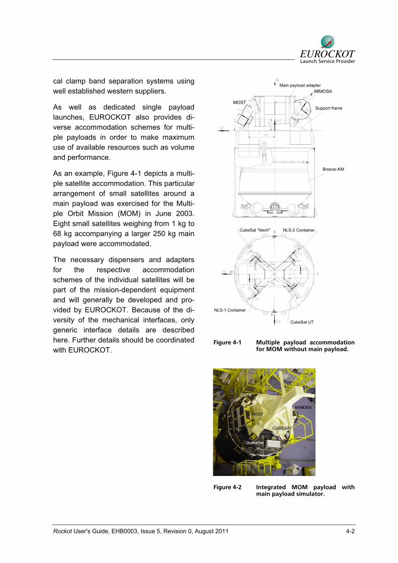
As an example, Figure 4-1 depicts a multi-ple satellite accommodation. This particular arrangement of small satellites around a main payload was exercised for the Multi-ple Orbit Mission (MOM) in June 2003. Eight small satellites weighing from 1 kg to 68 kg accompanying a larger 250 kg main payload were accommodated.
The necessary dispensers and adapters for the respective accommodation schemes of the individual satellites will be part of the mission-dependent equipment and will generally be developed and pro-vided by EUROCKOT. Because of the di-versity of the mechanical interfaces, only generic interface details are described here. Further details should be coordinated with EUROCKOT.
Main Payload Adapter
Support Frame
MIMOSA
MOST
Breeze KM
CubeSat "litech"
NLS-1 Container
NLS-2 Container
CubeSat UT
Breeze-KM
Support frame
Main payload adapter
Figure 4-1 Multiple payload accommodation for MOM without main payload.
Figure 4-2 Integrated MOM payload with main payload simulator.
Rockot User's Guide, EHB0003, Issue 5, Revision 0, August 2011 4-3
4.1.2 Usable Volume for Payload
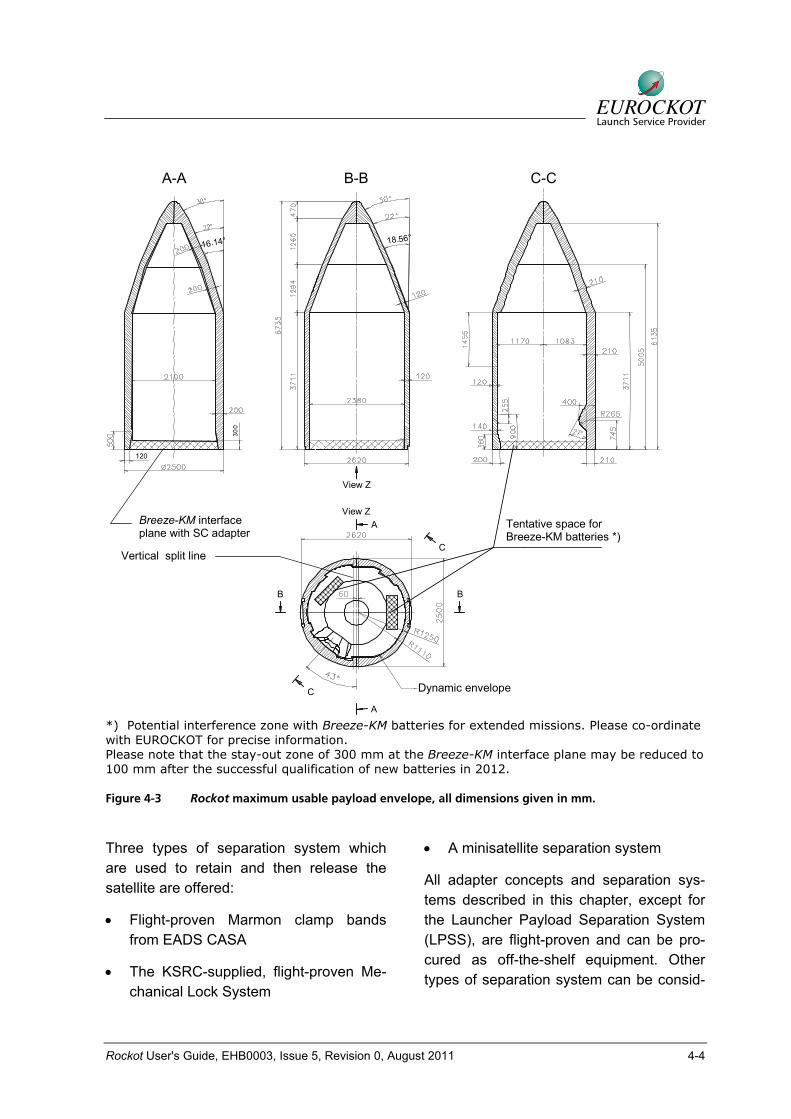
The layout of the payload-usable volume, which is the maximum dynamic envelope above the Breeze-KM interface plane, is shown in Figure 4-3.
This figure reflects the maturity of the com-mercial payload fairing design which per-formed its maiden flight in May 2000. The usable volume has been defined conserva-tively taking into account the following items:
• Maximum dynamic movement of fairing
• Maximum manufacturing tolerances of the fully integrated fairing
• Maximum mounting error of the fairing
• A minimum guaranteed clearance be-tween the spacecraft and the fairing
• Estimated maximum spacecraft dy-namic movement for a typical base- mounted configuration. For a side-mounted spacecraft located on a verti-cal payload dispenser, this value will be the subject of a dedicated dynamic analysis.
• Estimated maximum spacecraft mount-ing error and manufacturing tolerance of a typical base-mounted adapter sys-tem
EUROCKOT can also provide a three-dimensional -IGES- file for a preliminary spacecraft accommodation investigation by the Customer.
Customers may in certain cases to exceed the maximum dynamic envelope shown above. However, the acceptance of such a case is subject to a detailed clearance
analysis following a coupled loads analysis and will involve the assessment of all available margins within the envelope. It should be noted that EUROCKOT recom-mends to all Customers with payload ele-ments that are predicted to have less than 40 mm clearance from the maximum us-able envelope, e.g. antenna, solar arrays etc., should contact EUROCKOT directly for precise determination of actual clear-ances.
4.1.3 Spacecraft Accessibility
Mechanical access to the payload after encapsulation is not foreseen as a stan-dard service. Principally, fairing access hatches are possible provided that an ac-ceptable cleanliness scenario at the Launch Pad can be agreed. However, ac-cess via umbilical connectors will be pro-vided during any operation phase after encapsulation, e. g. for battery trickle charging, communication, etc. Should a late intervention at the spacecraft be nec-essary, the upper composite will be de-stacked from the booster unit and trans-ported back to the payload integration facil-ity.
4.1.4 Separation Systems
This section describes potential options for providing high quality attachment and separation between the Customer’s space-craft and the Breeze-KM upper stage. The selection of one of these interface solutions is driven by constraints such as spacecraft geometry, mass and related properties, stiffness and so on. However, cost aspects and maximum acceptable mechanical loads during spacecraft separation are design drivers, as well.
Rockot User's Guide, EHB0003, Issue 5, Revision 0, August 2011 4-4
SECTION A-ASECTION B-BSECTION C-C
Dynamic Envelope
16.14° 18.56°
120
300
Tentative Space forLV Batteries *)
Breeze InterfacePlane S/C Adapter
A-A B-B C-C
Vertical split line
Breeze-KM interface plane with SC adapter
Tentative space for Breeze-KM batteries *)
View Z
View Z
C
C
B B
A
A
Dynamic envelope
*) Potential interference zone with Breeze-KM batteries for extended missions. Please co-ordinate with EUROCKOT for precise information. Please note that the stay-out zone of 300 mm at the Breeze-KM interface plane may be reduced to 100 mm after the successful qualification of new batteries in 2012.
Figure 4-3 Rockot maximum usable payload envelope, all dimensions given in mm.
Three types of separation system which are used to retain and then release the satellite are offered:
• Flight-proven Marmon clamp bands from EADS CASA
• The KSRC-supplied, flight-proven Me-chanical Lock System
• A minisatellite separation system
All adapter concepts and separation sys-tems described in this chapter, except for the Launcher Payload Separation System (LPSS), are flight-proven and can be pro-cured as off-the-shelf equipment. Other types of separation system can be consid-
Rockot User's Guide, EHB0003, Issue 5, Revision 0, August 2011 4-5
ered and developed upon Customer's re-quest. The Customer can also provide his own separation system. In this case the choice of the adapter has to be agreed with EUROCKOT.
The separation system also comprises spring loaded pushers, separation monitor-ing switches and umbilical connectors at-tached to suitable brackets which are items to be accommodated in the payload adapter. The pushers can be selected for separation velocities between 0.1 and 0.8 m/s upon Customer's request. The spring pushers are so aligned that the resultant force will act along the spacecraft’s centre of mass in the desired separation direction, thereby reducing the spacecraft tip-off rate.
4.1.4.1 Clamp Band Separation Systems
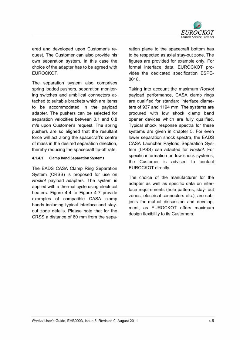
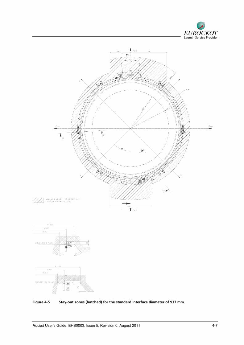
The EADS CASA Clamp Ring Separation System (CRSS) is proposed for use on Rockot payload adapters. The system is applied with a thermal cycle using electrical heaters. Figure 4-4 to Figure 4-7 provide examples of compatible CASA clamp bands including typical interface and stay-out zone details. Please note that for the CRSS a distance of 60 mm from the sepa-
ration plane to the spacecraft bottom has to be respected as axial stay-out zone. The figures are provided for example only. For formal interface data, EUROCKOT pro-vides the dedicated specification ESPE-0018.
Taking into account the maximum Rockot payload performance, CASA clamp rings are qualified for standard interface diame-ters of 937 and 1194 mm. The systems are procured with low shock clamp band opener devices which are fully qualified. Typical shock response spectra for these systems are given in chapter 5. For even lower separation shock spectra, the EADS CASA Launcher Payload Separation Sys-tem (LPSS) can adapted for Rockot. For specific information on low shock systems, the Customer is advised to contact EUROCKOT directly.
The choice of the manufacturer for the adapter as well as specific data on inter-face requirements (hole patterns, stay- out zones, electrical connectors etc.), are sub-jects for mutual discussion and develop-ment, as EUROCKOT offers maximum design flexibility to its Customers.
Rockot User's Guide, EHB0003, Issue 5, Revision 0, August 2011 4-6
LV Interface Ring
SC Interface Ring
CRSS Clamp Ring (open)Pyrolock
Umbilical Connector Bracket (2 Brackets)
Adapter
Catcher
SC interface ring Umbilical connector bracket (2 pieces)
LV interface ring
CRSS clamp ring (open)Pyrolock
Adapter
Figure 4-4 CASA CRSS Clamp Ring Separation System installation with KSRC pyrolock.
Rockot User's Guide, EHB0003, Issue 5, Revision 0, August 2011 4-7
Figure 4-5 Stay-out zones (hatched) for the standard interface diameter of 937 mm.
Rockot User's Guide, EHB0003, Issue 5, Revision 0, August 2011 4-8
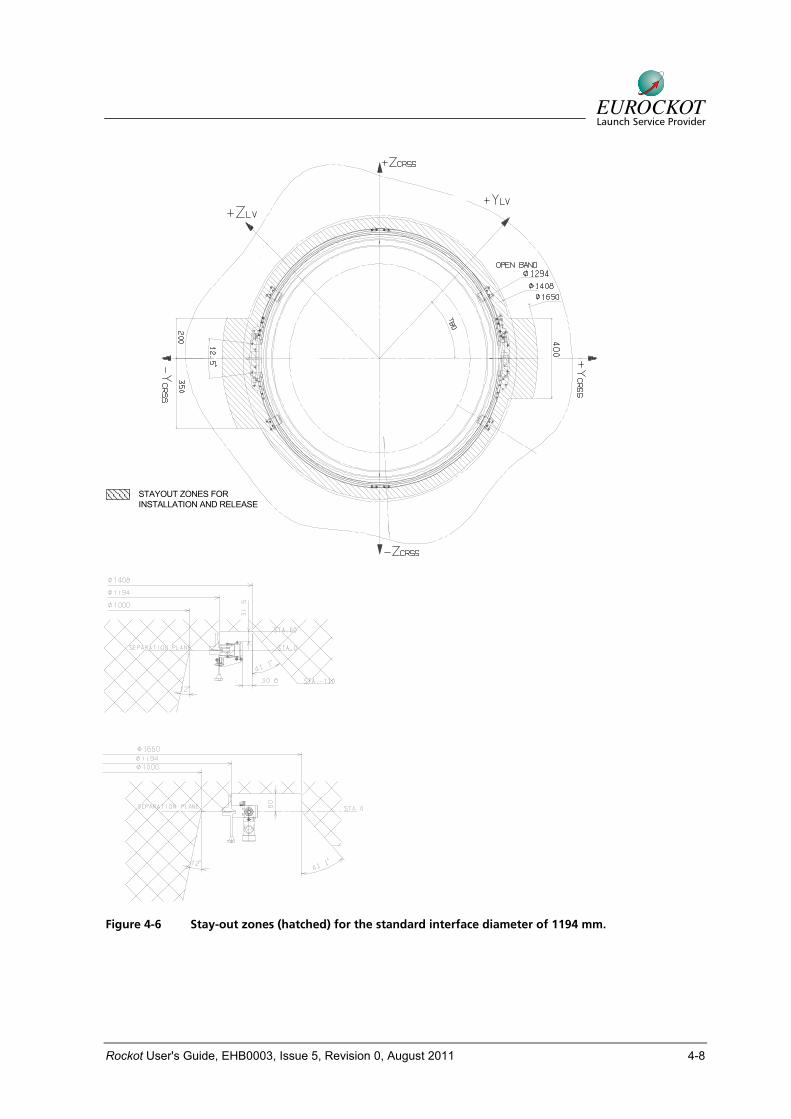
STAYOUT ZONES FORINSTALLATION AND RELEASE
Figure 4-6 Stay-out zones (hatched) for the standard interface diameter of 1194 mm.
Rockot User's Guide, EHB0003, Issue 5, Revision 0, August 2011 4-9
Pyro-nut
Pyro-nut support Connector support
Main beam Bushing
(a)
(b)
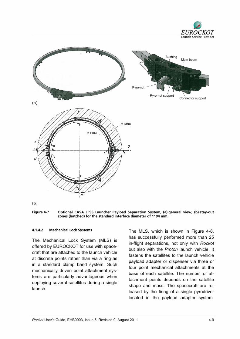
Figure 4-7 Optional CASA LPSS Launcher Payload Separation System, (a) general view, (b) stay-out zones (hatched) for the standard interface diameter of 1194 mm.
4.1.4.2 Mechanical Lock Systems
The Mechanical Lock System (MLS) is offered by EUROCKOT for use with space-craft that are attached to the launch vehicle at discrete points rather than via a ring as in a standard clamp band system. Such mechanically driven point attachment sys-tems are particularly advantageous when deploying several satellites during a single launch.
The MLS, which is shown in Figure 4-8, has successfully performed more than 25 in-flight separations, not only with Rockot but also with the Proton launch vehicle. It fastens the satellites to the launch vehicle payload adapter or dispenser via three or four point mechanical attachments at the base of each satellite. The number of at-tachment points depends on the satellite shape and mass. The spacecraft are re-leased by the firing of a single pyrodriver located in the payload adapter system.
Rockot User's Guide, EHB0003, Issue 5, Revision 0, August 2011 4-10
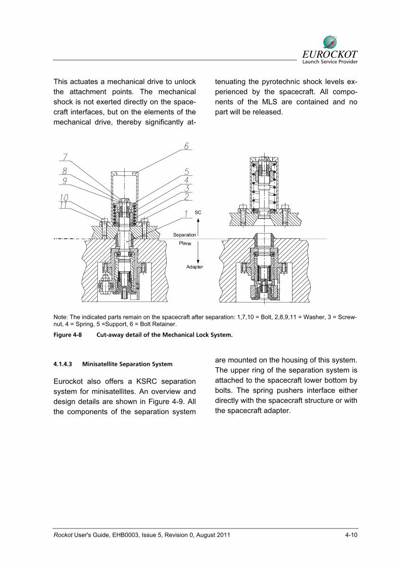
This actuates a mechanical drive to unlock the attachment points. The mechanical shock is not exerted directly on the space-craft interfaces, but on the elements of the mechanical drive, thereby significantly at-
tenuating the pyrotechnic shock levels ex-perienced by the spacecraft. All compo-nents of the MLS are contained and no part will be released.
Plane
SC
Adapter
Separation
Note: The indicated parts remain on the spacecraft after separation: 1,7,10 = Bolt, 2,8,9,11 = Washer, 3 = Screw-nut, 4 = Spring, 5 =Support, 6 = Bolt Retainer.
Figure 4-8 Cut-away detail of the Mechanical Lock System.
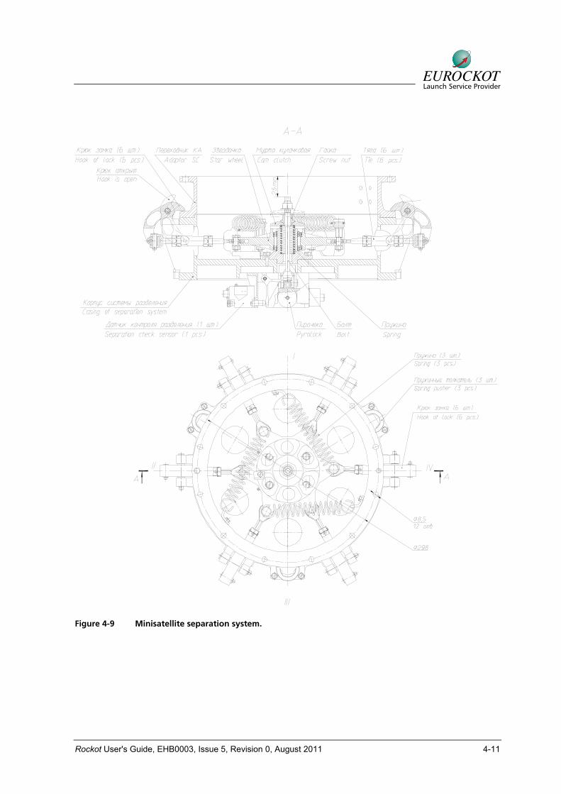
4.1.4.3 Minisatellite Separation System
Eurockot also offers a KSRC separation system for minisatellites. An overview and design details are shown in Figure 4-9. All the components of the separation system
are mounted on the housing of this system. The upper ring of the separation system is attached to the spacecraft lower bottom by bolts. The spring pushers interface either directly with the spacecraft structure or with the spacecraft adapter.
Rockot User's Guide, EHB0003, Issue 5, Revision 0, August 2011 4-11
Figure 4-9 Minisatellite separation system.
Rockot User's Guide, EHB0003, Issue 5, Revision 0, August 2011 4-12
4.1.5 Payload Adapters
Payload adapter and dispenser systems, which are the structures supporting the chosen separation system, are described in this section.
The payload adapter also accommodates the spring loaded pushers, separation monitoring switches, and umbilical connec-tors which are components of the separa-tion system (section 4.1.4).
4.1.5.1 Clamp Band Separation System Adapters
Adapter systems compatible with classical Marmon-type V-shaped clamp band sepa-ration systems are offered by EUROCKOT. Such payload adapter types are flight-proven and can be offered in two sizes, 937 mm and 1194 mm. As an option, also other clamp band sizes can be adapted for Rockot/Breeze-KM if required.
The payload adapters have the shape of either a cone or a cylinder and are offered as either aluminium or carbon fibre struc-tures or a combination of both. The pay-load adapter is bolted to the top of the equipment bay of the Breeze-KM upper stage. The forward face of the payload adapter is machined into a ring with pre-defined dimensions according to the re-quirements of the clamp band separation system chosen. The payload adapter may also be split into a lower part which inter-faces to the upper stage and the LV inter-face ring that interfaces the clamp band and the spacecraft. The spacecraft inter-face ring is pressed on top of this surface against to the adapter by adequate ten-sioning of the clamp band.
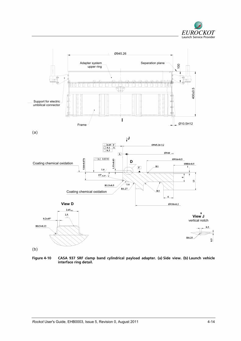
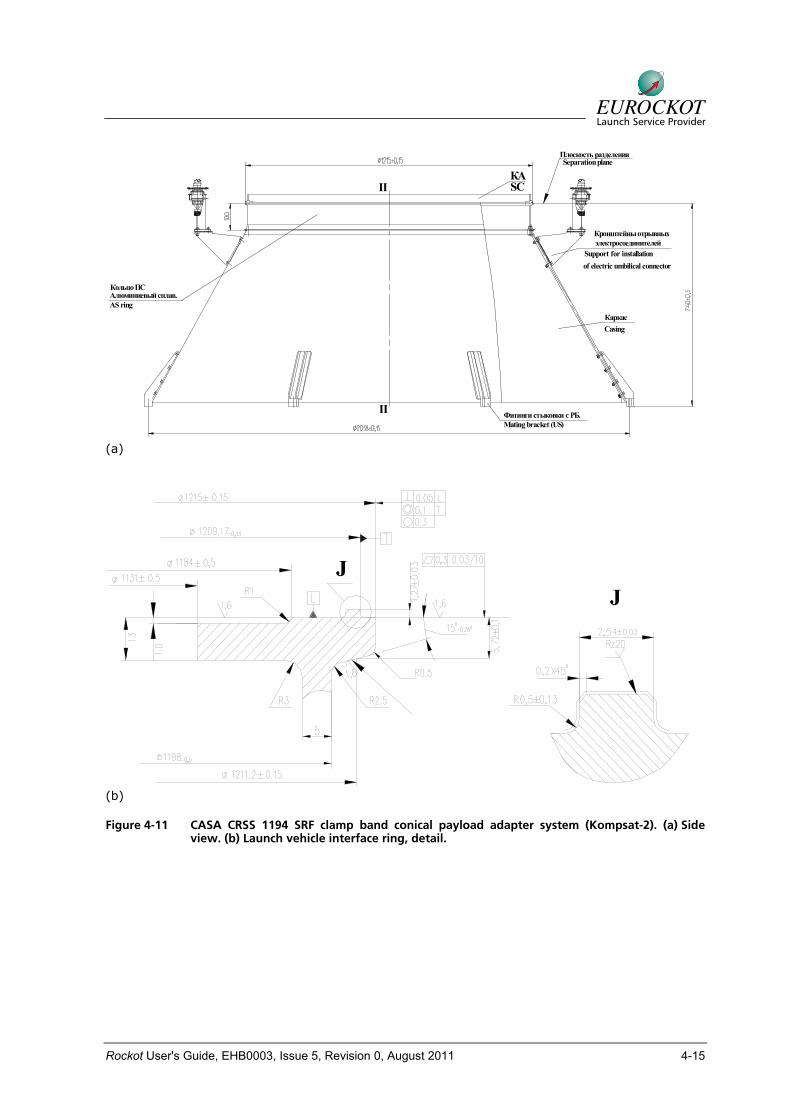
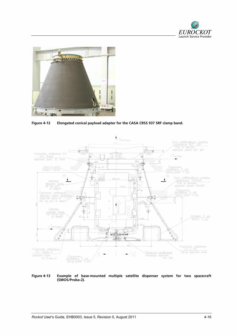
The upper part of the adapter allows for the accommodation of electrical connectors to the spacecraft via support brackets. The bracket position can be varied on a case-by-case basis, each bracket also allows ± 4 mm horizontal and ± 2 mm vertical ad-justment for fine tuning. The lower part of the adapter allows for positioning of sepa-ration system components and sensors. Figure 4-10 depicts a flight qualified cylindrical aluminium payload adapter with 400 mm height together with interface de-tails. This cylindrical adapter type is cur-rently in modification for the 1194 mm clamp band. Figure 4-11 shows a conical shaped adapter with an 1194 mm interface ring diameter specially developed for the Kompsat-2 spacecraft interface. In the ma-jority of cases the payload adapter consists of two parts, namely an upper part and a lower part bolted together. The upper part provides the launch vehicle interface ring and is manufactured from aluminium alloy. The lower part of the adapter which inter-faces to the launch vehicle can be made from a carbon fibre or aluminium structure. A distinctive feature of these adapter de-signs is that, while the height of the lower part may vary for different payloads, the payload adapter interface remains un-changed. Finally, Figure 4-12 shows a conical payload adapter with an extended length for the CRSS 937 SRF clamp band.
Two spacecraft on top of each other can be launched on Rockot/Breeze-KM using Multi-Satellite Dispenser systems (MSD). An example of two base mounted satellites with clamp band separation systems de-signed for the SMOS/Proba-2 mission (2009) is shown in Figure 4-13. The smaller spacecraft is transported under-neath the conical payload adapter of the
Rockot User's Guide, EHB0003, Issue 5, Revision 0, August 2011 4-13
larger spacecraft and attached with the minisatellite separation system (Figure 4-9).
The spacecraft ring interfacing with the clamp band and adapter on the launch vehicle side is generally designed by the Customer. While the spacecraft ring inter-face dimensions are fix, the cross section is selected by the Customer, who is re-sponsible for the structural integrity of the spacecraft ring. EUROCKOT will check together with KSRC and EADS CASA
Espacio that the cross section of the ring is still enough to ensure the correct function of the interface. Therefore, the Customer shall provide the spacecraft design concept to EUROCKOT for veri-fication before releasing the design to manufacturing. Details for the EADS CASA CRSS 937 and 1194 SRF clamp band separation system, the launch vehicle adapter and the spacecraft in-terface ring are given in the latest issue of EUROCKOT specification ESPE-0018.
Rockot User's Guide, EHB0003, Issue 5, Revision 0, August 2011 4-14
∅10,5H12
Плоскость разделения
100
ановки
теля
400±
0,5
10
∅945.26
Каркас I
Верхнее кольцо ПС Separation plane Upper ring of the AS
Frame
alataion of l
Ø945.26
Separation planeAdapter systemupper ring
Frame
Support for electric umbilical connector
Ø10.5H12
400±
0.5
100
(a)
Coating: chemical oxidation (
5.84±0.076
15°
2,65
0,2x45°
R0,5±0,13
2,5
-0,1
D
Coating: chemical oxidation (
R3R1.27
13
0.5
R0.25 0.5
6
O930±0.2
Vertical notch
J
O884±0,5
O916±0,5
O945.26
0.3O940
1
6
R1
1.53±0.03
1.6
1.6
-0,25°
R1,5±0,5
D
Å
F
-0.2
JFÅ
0.050.1
-0.00+0.15
J
View D
D Coating chemical oxidation
Coating chemical oxidation
View Jvertical notch
Ø945.26
Ø916±0.5
Ø884±0.5
R1.5±0.5
2.65-0.1
2.50.2x45°
R0.5±0.13
15°-0.25°
5.84
±0.0
76
1.53
±0.0
3
0.5
6
13
(b)
Figure 4-10 CASA 937 SRF clamp band cylindrical payload adapter. (a) Side view. (b) Launch vehicle interface ring detail.
Rockot User's Guide, EHB0003, Issue 5, Revision 0, August 2011 4-15
AS ring
Кольцо ПС
II
II
Casing Каркас
Фитинги стыковки с РБ.
электросоединителей
of electric umbilical connector
Кронштейны отрывных
Separation planeПлоскость разделения
Support for installation
SСКА
Mating bracket (US)
Алюминиевый сплав.
(a)
JJ
(b)
Figure 4-11 CASA CRSS 1194 SRF clamp band conical payload adapter system (Kompsat-2). (a) Side view. (b) Launch vehicle interface ring, detail.
Rockot User's Guide, EHB0003, Issue 5, Revision 0, August 2011 4-16
Figure 4-12 Elongated conical payload adapter for the CASA CRSS 937 SRF clamp band.
Figure 4-13 Example of base-mounted multiple satellite dispenser system for two spacecraft (SMOS/Proba-2).
Rockot User's Guide, EHB0003, Issue 5, Revision 0, August 2011 4-17
4.1.5.2 Mechanical Lock System Payload Adapters
Payload adapters designed for use with the MLS separation system are individually configured to suit the particular spacecraft design. This customisation allows ex-tremely lightweight and low height adapters to be realized. EUROCKOT and KSRC have designed, manufactured and suc-cessfully flown over two dozen systems of this kind for commercial Customers. These adapters are also well suited for multiple satellite accommodation.
The mass and height of the adapter de-pend on the final arrangement, i.e. dimen-sions of the spacecraft and number of at-tachment points. Spacecraft interface brackets that stay on the spacecraft after separation will have a mass of approxi-mately 2 to 10 kg depending on mass and geometry of the spacecraft (Figure 4-8). Adapter heights as low as 100 mm can be realized.
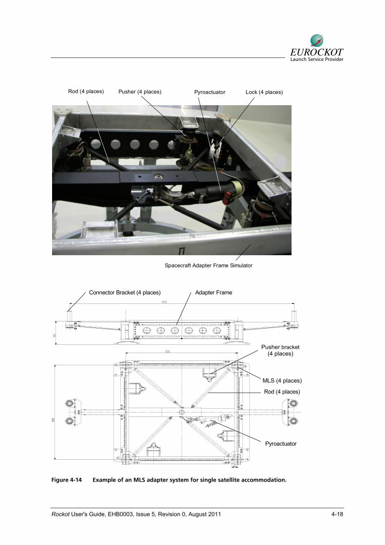
An example of a single satellite adapter using the mechanical lock system is shown in Figure 4-14. It incorporates the me-chanical lock separation components in-cluding pyro-actuator, rods, spring push-ers, connectors and bonding provisions. The satellite is fastened to the launch vehi-cle payload adapter via four or three me-
chanical locks using four or three brackets at the base of each satellite. The number of attachment points depends on the satel-lite shape and mass. Separation is achieved by igniting the pyro-actuator which in turn rotates the mechanical locks via the mechanism rods releasing the spacecraft adapter frame. The spacecraft is then pushed away by spring pushers. Shock is not exerted directly on the space-craft interfaces but on the parts of the me-chanical drive, thus significantly attenuat-ing the pyrotechnic shock levels at the spacecraft.
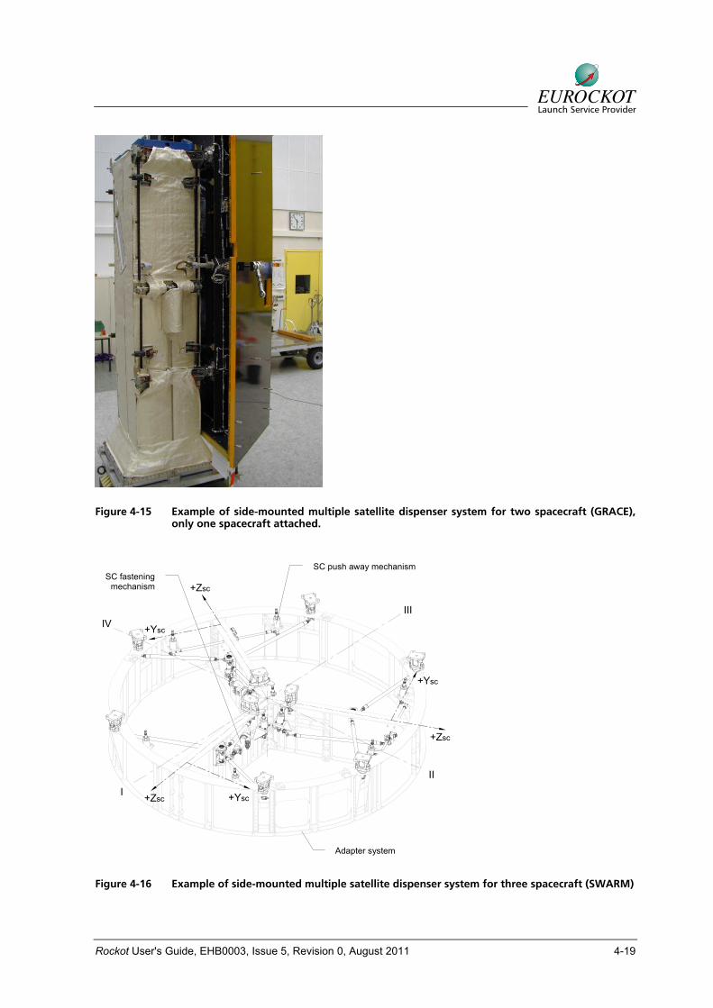
EUROCKOT is able to provide customised payload adapter and dispenser systems for multi satellite deployment upon Customer request. EUROCKOT and its parent com-pany KSRC have significant experience in the design, manufacture and qualification of these systems. Figure 4-15 shows an example of a side-mounted multiple satel-lite dispenser. This particular system was designed and qualified for the NASA-DLR GRACE mission. The riveted aluminium structure incorporates the mechanical lock system described and allows two space-craft to be accommodated side-mounted. Figure 4-16 depicts the multiple satellite dispenser developed for the ESA SWARM mission with the capability to attach and release three base-mounted spacecraft.
Rockot User's Guide, EHB0003, Issue 5, Revision 0, August 2011 4-18
Pusher (4 places) Lock (4 places)Rod (4 places) Pyroactuator
Spacecraft Adapter Frame Simulator
Connector Bracket (4 places)
Lock (4 places)
Pusher Bracket(4 places)
Pyroactuator
Adapter Frame
Rod (4 places)
Pusher bracket (4 places)
MLS (4 places)
Figure 4-14 Example of an MLS adapter system for single satellite accommodation.
Rockot User's Guide, EHB0003, Issue 5, Revision 0, August 2011 4-19
Figure 4-15 Example of side-mounted multiple satellite dispenser system for two spacecraft (GRACE), only one spacecraft attached.
I
III
II
IV
+Zsc
+Zsc
+Zsc
+Ysc
+Ysc
+Ysc
SC push away mechanism
Adapter system
SC fastening mechanism
Figure 4-16 Example of side-mounted multiple satellite dispenser system for three spacecraft (SWARM)
Rockot User's Guide, EHB0003, Issue 5, Revision 0, August 2011 4-20
4.2 Electrical Interfaces
This section describes the interfaces em-ployed to provide electrical links between the spacecraft’s umbilical connectors and the Customer’s EGSE for spacecraft use. The electrical interfaces include the launch vehicle to spacecraft on-board electrical interfaces, EGSE interfaces, and teleme-try/command links.
4.2.1 On-board Interfaces
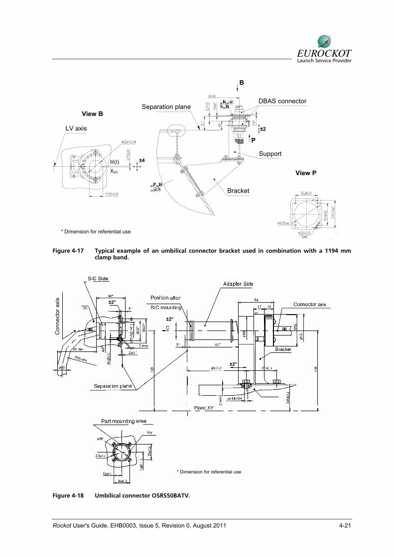
The on-board electrical interfaces provide links from the spacecraft’s umbilical con-nectors via the ground cable network to the spacecraft EGSE, including power circuits, checkout and control circuits, and teleme-try and command links. Examples of the umbilical connector brackets that can usu-ally be accommodated on the payload adapter are illustrated in Figure 4-17 and Figure 4-18. The brackets may vary in de-sign depending on their location on the spacecraft and electrical connector types.
4.2.1.1 Umbilical Connectors
As a baseline EUROCKOT proposes the use of four 50-pin Russian connectors type OS RS50BATV. The connectors are mounted on the payload adapter by means of suitable brackets. Wires up to AWG 22 size with a cross section of 0.35 mm2 can be accommodated by the OS RS50BATV connectors. The maximum permissible cross section area of the accommodated wire is 0.5 mm2 on the condition that it is used via a pin and not more than 20 pins are used on the contact region connector perimeter. The number of connectors and number of pins per connector can be se-lected according to the Customer's needs. Hence, the spacecraft connector configura-tion shown in is only an example. Because of the potential impacts on the separation
dynamics, alternative connector types have to be mutually agreed with EUROCKOT.
4.2.1.2 Separation Verification
The spacecraft manufacturer has to pro-vide spacecraft separation monitoring cir-cuits as jumpers in each of the spacecraft umbilical connectors for use by the launch vehicle telemetry. Separation monitoring circuits as jumpers on Launch Vehicle side are provided to be used by Spacecraft te-lemetry.
4.2.1.3 Interface Electrical Constraints
The following restrictions on the spacecraft to launch vehicle electrical interfaces will apply:
• The maximum voltage on the space-craft umbilical connectors must not ex-ceed 100 V. At lift-off, the transit cable must be de-energised both on the spacecraft and EGSE side, except for the separation jumpers.
• The EGSE provided by the spacecraft contractor must be designed to inhibit voltages above 100 V.
• GSE power through the spacecraft umbilical connectors must be switched off automatically if the nominal operat-ing current is exceeded by 50% over a 0.2 s period. The EGSE supplied by the Customer must be designed so that it will cause automatic switch-off if the nominal operating current of the space-craft lines exceeds 100% over a 0.1 s period.
• Not later than 20 s before spacecraft separation the current at spacecraft to launch vehicle interface should be lim-ited to 100 mA, except for the separa-tion jumpers.
Rockot User's Guide, EHB0003, Issue 5, Revision 0, August 2011 4-21
Separation plane
LV axis
„@S„P„R
Support
Bracket
„K„@S„R
+Xsc(-Xsc)
III(I)
C-C
B
B
*Dimension for referential use
DBAS Connector
P
P±4„}„}
±4„}„}
±2„}„}LV axis
View B
B
DBAS connector
Support
Separation plane
Bracket
P
View P
±4 III(I)
XSC
±2
* Dimension for referential use
Figure 4-17 Typical example of an umbilical connector bracket used in combination with a 1194 mm clamp band.
Con
nect
or a
xis
* Dimension for referential use
±2*
±2*
±2*
Figure 4-18 Umbilical connector OSRS50BATV.
Rockot User's Guide, EHB0003, Issue 5, Revision 0, August 2011 4-22
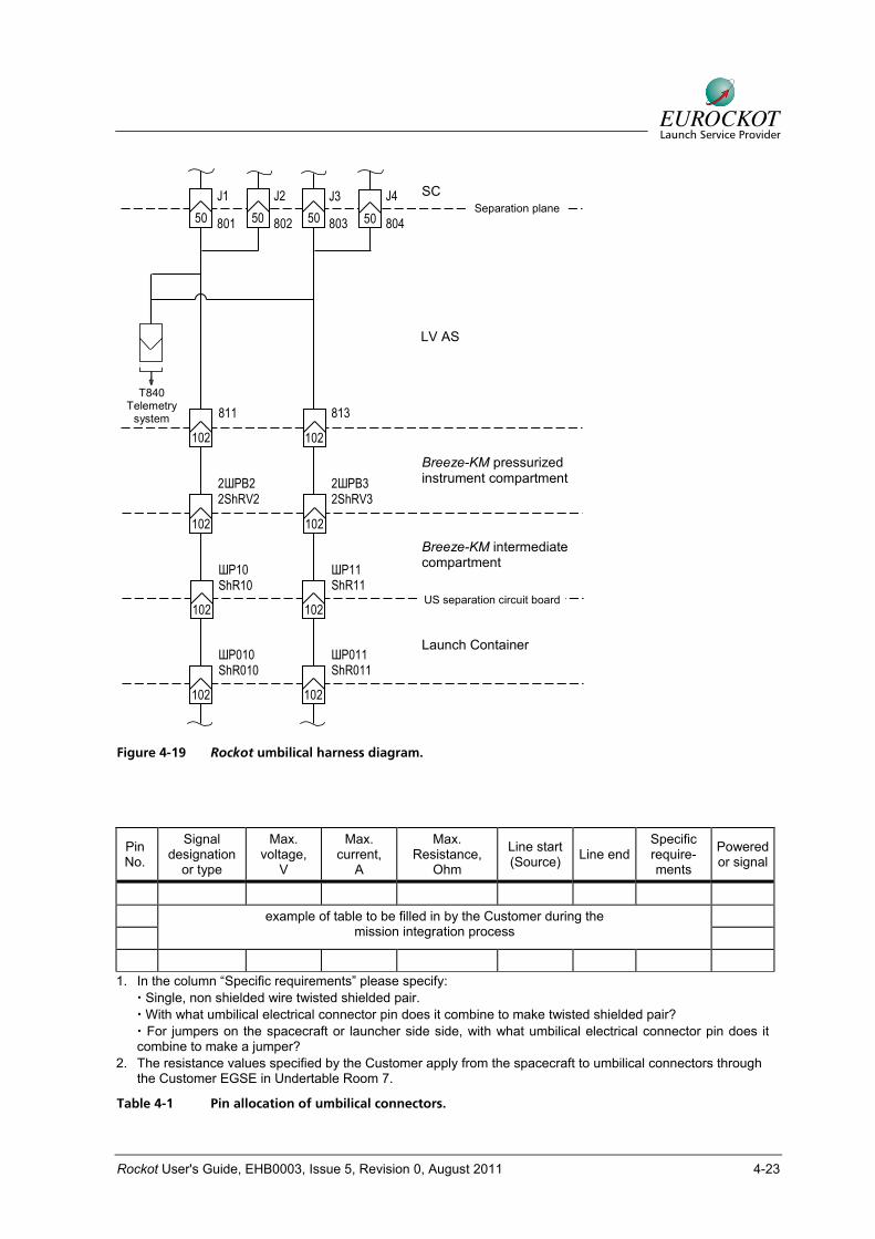
4.2.1.4 Umbilical Harness Configuration and Specifications
The standard Rockot umbilical harnesses is schematically shown in Figure 4-19. Four spacecraft umbilical connectors 801 to 804 may accommodate up to 200 transit lines. Any telemetry channel for the moni-toring of the spacecraft interface environ-ment will share this budget of lines with the spacecraft. These lines lead to the connec-tors 811 and 813 of type OS 9R102 (OC 9P102) with 102 pins each. These connectors are mounted on the payload adapter / Breeze-KM interface. Telemetry circuits from the umbilical connectors 801 through 804 are routed into connector 840 and from there to the upper stage teleme-try. From connectors 811 and 813 the cir-cuits are routed into connectors ShR10 and ShR11 with 102 pins each on the Breeze-KM umbilical plate to the ground interface. The launch container plate ac-commodates electrical connectors of type OS RRM47 with 102 pins each.
The circuitry of the payload adapter har-ness from the spacecraft umbilical connec-tors 801 through 804 to connectors 811 and 813 is developed on the basis of the Customer’s input data and is payload-specific. Table 4-1 shows the pin allocation requirements. It is however limited by the capacities of the harness of the Breeze-KM that is specified in Table 4-2. The harness length from the spacecraft umbilical con-nectors 801 to 804 to connectors 811 and 813 depends on the payload adapter de-sign.
The harness beyond the connectors 811 and 813 down to the spacecraft EGSE in Undertable Room 7 is standardised transit wiring via the upper stage and the station-
ary column. The wires are symmetrically distributed between the two umbilical ca-bles. Wires of type MC-15-11-0.35 are used. The maximum operating voltage is 100 V on the spacecraft umbilical connec-tors, the maximum operating current is 1.5 A per transit wire. All transit wires have a 0.35 mm2 cross-section. The total length of the on-board transit lines from connectors 811 and 813 on the Breeze-KM pressur-ised equipment bay to connectors ShR010 and ShR011 on the container plate is less than 18 m.
Neglecting the resistance of the payload harness, the resistance of the on-board cable network from spacecraft connectors 801 through 804 to the connectors on the plate of the launch container ShR010 and ShR011 is not more than 1 Ohm. The shields of the twisted pairs and single shielded wires are isolated from the cable jackets and launch vehicle connector shells and terminated at the appropriate electrical connector pins.
The insulation resistance of the transit lines should be at least 10 MOhm.
A high reliability is ensured by:
• Highly reliable components operated in a derated mode
• Verified service life margins as to oper-ating time, storage time and number of actuations
• Verified robustness and environmental resistance margins
Rockot User's Guide, EHB0003, Issue 5, Revision 0, August 2011 4-23
Breeze-KM pressurized instrument compartment
LV AS
SC
813811T840
Telemetry system
Breeze-KM intermediate compartment
102 102
102 102
Separation plane50 50 50 50 801 802 803 804
J1 J2 J3 J4
US separation circuit board102 102
Launch Container
102 102
2ШРВ2 2ShRV2
2ШРВ3 2ShRV3
ШР10 ShR10
ШР11 ShR11
ШР010 ShR010
ШР011 ShR011
Figure 4-19 Rockot umbilical harness diagram.
Pin No.
Signal designation
or type
Max. voltage,
V
Max. current,
А
Max. Resistance,
Ohm
Line start(Source) Line end
Specific require-ments
Powered or signal
example of table to be filled in by the Customer during the mission integration process
1. In the column “Specific requirements” please specify:
Single, non shielded wire twisted shielded pair. With what umbilical electrical connector pin does it combine to make twisted shielded pair? For jumpers on the spacecraft or launcher side side, with what umbilical electrical connector pin does it
combine to make a jumper? 2. The resistance values specified by the Customer apply from the spacecraft to umbilical connectors through
the Customer EGSE in Undertable Room 7.
Table 4-1 Pin allocation of umbilical connectors.
Rockot User's Guide, EHB0003, Issue 5, Revision 0, August 2011 4-24
Wire cross section, mm2 Transit wire type Quantity Total transit wires Flight harness Ground harness
Note
Single, no shield 100 100 0.35 2.5
Single shielded 30 30 0.35 1.5
Twisted shielded pairs 34 68 0.35 2.5
Shield 2 2 0.35 >1.5
Total: 200
Table 4-2 Ground wiring capacities.
4.2.1.5 Matchmate / Electrical Checkout
The Matchmate and electrical checkout between the spacecraft interface and the payload adapter is strongly recommended and should preferably be conducted at the spacecraft manufacturer's facility.
4.2.1.6 Spacecraft Electrical Interface Input Data Requirements
For the purpose of Rockot mission adapta-tion, the Customer shall provide input data containing specifications for each transit wire line per umbilical connector, as shown in Table 4-1.
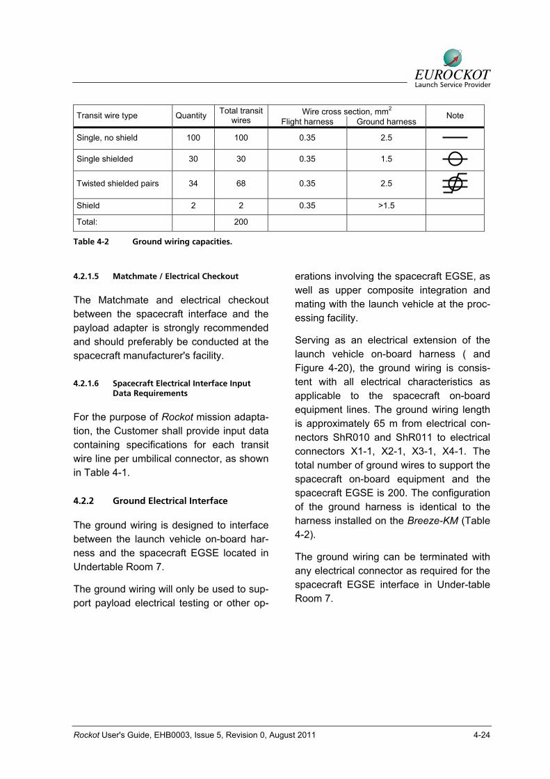
4.2.2 Ground Electrical Interface
The ground wiring is designed to interface between the launch vehicle on-board har-ness and the spacecraft EGSE located in Undertable Room 7.
The ground wiring will only be used to sup-port payload electrical testing or other op-
erations involving the spacecraft EGSE, as well as upper composite integration and mating with the launch vehicle at the proc-essing facility.
Serving as an electrical extension of the launch vehicle on-board harness ( and Figure 4-20), the ground wiring is consis-tent with all electrical characteristics as applicable to the spacecraft on-board equipment lines. The ground wiring length is approximately 65 m from electrical con-nectors ShR010 and ShR011 to electrical connectors X1-1, X2-1, X3-1, X4-1. The total number of ground wires to support the spacecraft on-board equipment and the spacecraft EGSE is 200. The configuration of the ground harness is identical to the harness installed on the Breeze-KM (Table 4-2).
The ground wiring can be terminated with any electrical connector as required for the spacecraft EGSE interface in Under-table Room 7.
Rockot User's Guide, EHB0003, Issue 5, Revision 0, August 2011 4-25
Fairing
Transport andLaunch ContainerExtension
UpperStage
S/C
Transport and LaunchContainer
LV
X1- ST X4- STX2- ST
X3- ST
50 50 50 50
X1-1 X2-1 X3-1X4-1UndertableRoom
Plate
X1-3 X2-3 X3-3 X4-3
Plate
Blockhouse(Optional)
ShR011
ShR010 C1
C2 Stationary Mast
S1
S2ШР011 ShR011
ШР010 ShR010
SC
Transport and launch container extension
Transport and launch container
Upper stage
Stationary mast
Figure 4-20 Launch site ground wiring diagram.
Rockot User's Guide, EHB0003, Issue 5, Revision 0, August 2011 4-26
4.2.3 Payload Grounding and Bonding
A passive approach is employed to protect the upper composite from hazardous static build-up. This approach includes bonding, creation of conductive surfaces, and grounding of the upper composite. The goal of the three techniques is
• to reduce the voltage potential between any two structural elements to a safe level,
• to ensure more effective cable shield-ing in order to eliminate any electro-static discharge (ESD) risk for the per-sonnel, and
• to reduce the voltage difference be-tween the upper composite or any of its components and the ground to zero.
The upper composite is designed
• to have no outer surface areas with voltage drops equal to the threshold beyond which a hazardous electrostatic discharge becomes possible,
• to ensure reliable electrical bonding of all metal elements of the structure so that a common reference, or a common electrical mass will be created,
• to ensure that any charge that may build up on an outer conductive surface of a dielectric component will leak a way to the common reference, and
• to enable grounding of the upper com-posite during integration, testing, fuel-ling, and transportation.
The usage of conductive coatings on the mating surfaces of the spacecraft and the
adapter system should be as defined be-low:
• Alodine 1200 conductive coating on the spacecraft side
• SECO electro conductive oxidizing on the adapter system side
• The transient resistance should not exceed 10 mOhm.
The upper composite ESD control is im-plemented by:
• the use of external surface materials with a volume resistivity of less than 105 Ohm · m,
• coating non-conductive materials with conductive layers to be bonded to the metal structure,
• the use of a conductive film, foil, grid or fabric to create a conductive outer sur-face in a dielectric,
• bonding each spacecraft to the dis-penser/adapter by means of two um-bilical straps,
• bonding any upper composite compo-nent with at least two points separated by the maximum possible distance, and
• electrically interconnecting all layers of each multi layer insulation blanket by bonding each blanket to the metal structure.
To prevent ESD, shield braiding and transit cable connector bodies should be con-nected to the launch vehicle.
On the pad, the upper composite is grounded via the launch vehicle metal structure. For this purpose, the spacecraft
Rockot User's Guide, EHB0003, Issue 5, Revision 0, August 2011 4-27
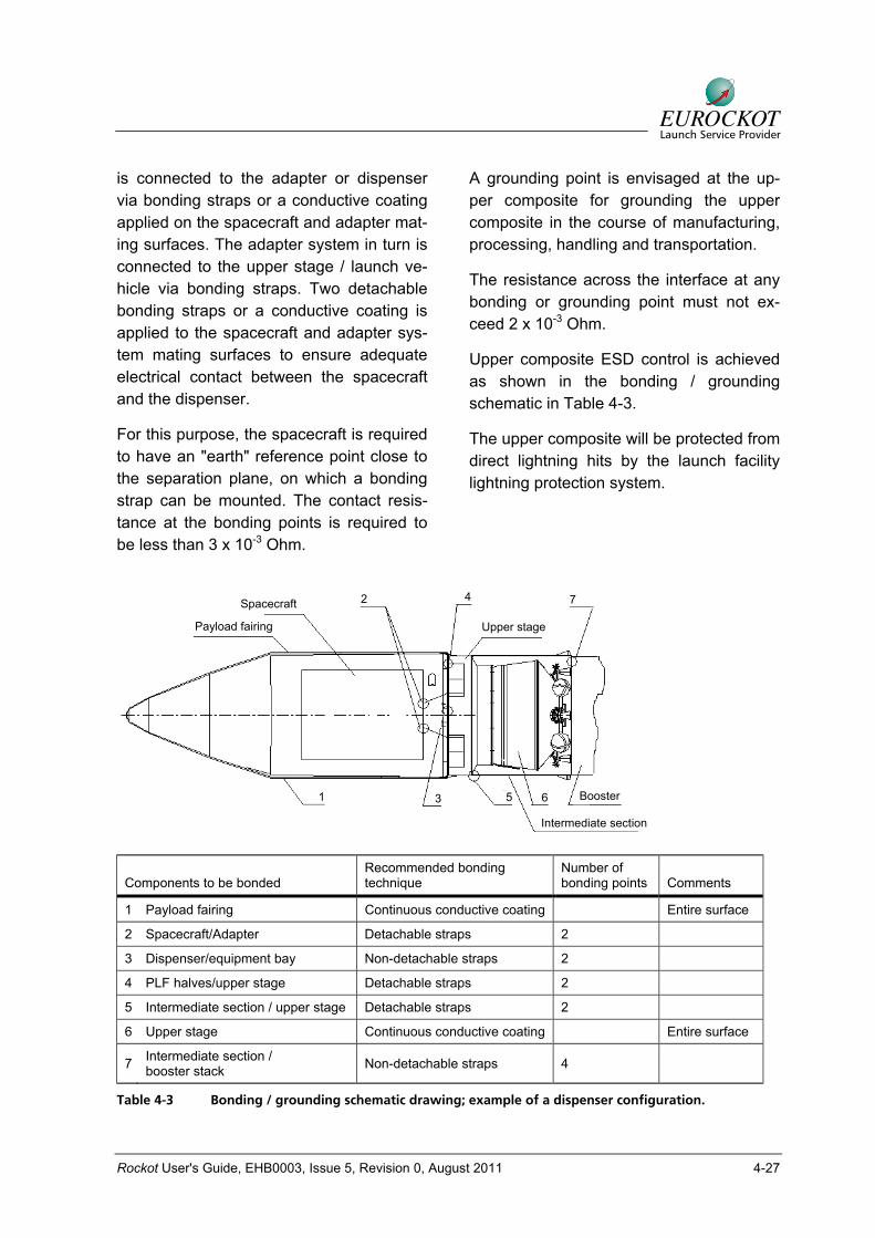
is connected to the adapter or dispenser via bonding straps or a conductive coating applied on the spacecraft and adapter mat-ing surfaces. The adapter system in turn is connected to the upper stage / launch ve-hicle via bonding straps. Two detachable bonding straps or a conductive coating is applied to the spacecraft and adapter sys-tem mating surfaces to ensure adequate electrical contact between the spacecraft and the dispenser.
For this purpose, the spacecraft is required to have an "earth" reference point close to the separation plane, on which a bonding strap can be mounted. The contact resis-tance at the bonding points is required to be less than 3 x 10⁻³ Ohm.
A grounding point is envisaged at the up-per composite for grounding the upper composite in the course of manufacturing, processing, handling and transportation.
The resistance across the interface at any bonding or grounding point must not ex-ceed 2 x 10⁻³ Ohm.
Upper composite ESD control is achieved as shown in the bonding / grounding schematic in Table 4-3.
The upper composite will be protected from direct lightning hits by the launch facility lightning protection system.
SATELLITESpacecraft
Payload fairing Upper stage
Booster
Intermediate section
1 3 5 6
742
Components to be bonded Recommended bonding technique
Number of bonding points Comments
1 Payload fairing Continuous conductive coating Entire surface
2 Spacecraft/Adapter Detachable straps 2
3 Dispenser/equipment bay Non-detachable straps 2
4 PLF halves/upper stage Detachable straps 2
5 Intermediate section / upper stage Detachable straps 2
6 Upper stage Continuous conductive coating Entire surface
7 Intermediate section / booster stack Non-detachable straps 4
Table 4-3 Bonding / grounding schematic drawing; example of a dispenser configuration.

Rockot User's Guide, EHB0003, Issue 5, Revision 0, August 2011 4-28
4.2.4 Payload Auxiliary Power Supply
4.2.4.1 Ground Auxiliary Power Supply
An uninterruptible power supply (UPS) is provided for the spacecraft EGSE. Please refer to Chapter 10 for further details.
4.2.4.2 In-flight Power Supply
At launch and in flight up to payload de-ployment, the payload can be supplied with power from the batteries of the upper stage as an optional service. The payload can be supplied with:
• Power (non-stabilised) with 24 to 30 VDC (voltage spikes of +/- 3 V might be encountered within this range), in dura-tion of up to 50 ms
• Maximum power supply 15 Ah for 7 hours with not more than 5 A
4.2.4.3 Optional Services
For a customer-supplied separation system power supply can be provided as an op-tion, with the following characteristics:
• Voltage: 28 VDC
• Current: pulse of 10 A and 30 ms dura-tion for up to 10 pulses
4.2.5 Separation Ignition Command
Discrete sequencing commands, gener-ated by the Rockot on-board computer, are available to the payload during the payload injection phase.
The number of command lines provided for the payload, as well as the signal charac-teristics, will be defined in detail in the In-terface Control Document. Discrete lines are provided through the same type of in-
terface connector as used for the payload auxiliary power lines.
The pyrotechnic command for spacecraft separation is a standard provision.
4.2.6 Payload Telemetry Support
The Rockot on-board telemetry system comprises a low rate telemetry device TA1 and a high rate telemetry device TA2. TA1 can operate up to end of Breeze-KM op-eration in three modes:
• DT: Direct transmission
• REC: Data record
• REP: Data replay
REC is used for the flight phases without visibility to downlink the data in the subse-quent visibility phase in the REP mode. The total storage capacity of TA1 is 64 Mbit.
The following channels in the TA1 system are assigned to the payload:
• 24 event channels with 1 bit
• 20 analogue channels with 8 bit resolu-tion
• 10 temperature channels with 8 bit re-solution
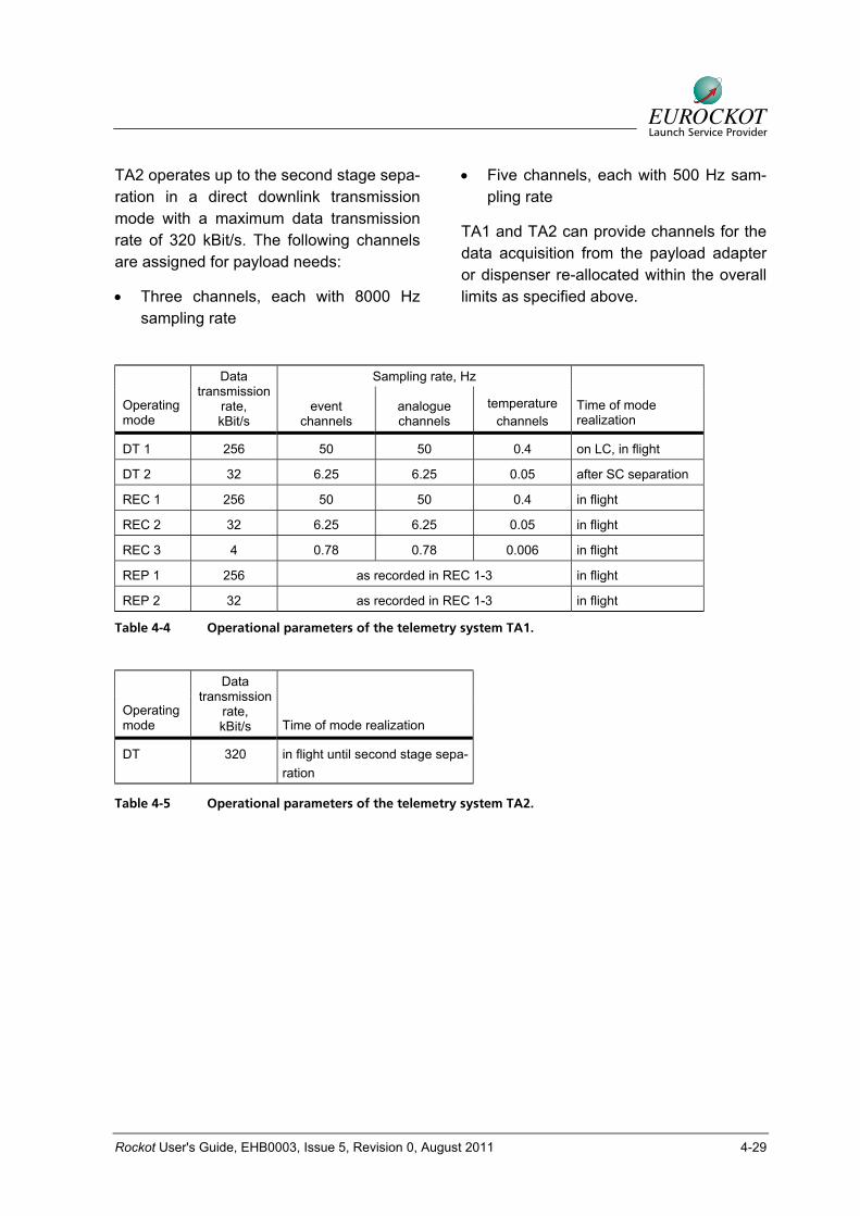
The maximum data sampling and downlink data rates depend on each other and on the operating mode as listed in Table 4-4 and Table 4-5.
TA1 also registers and transmits the status signals of the payload separation. The separation signals are generated by the LV separation detection devices.
Rockot User's Guide, EHB0003, Issue 5, Revision 0, August 2011 4-29
TA2 operates up to the second stage sepa-ration in a direct downlink transmission mode with a maximum data transmission rate of 320 kBit/s. The following channels are assigned for payload needs:
• Three channels, each with 8000 Hz sampling rate
• Five channels, each with 500 Hz sam-pling rate
TA1 and TA2 can provide channels for the data acquisition from the payload adapter or dispenser re-allocated within the overall limits as specified above.
Sampling rate, Hz
Operating mode
Data transmission
rate, kBit/s
event channels
analogue channels
temperature channels
Time of mode realization
DT 1 256 50 50 0.4 on LC, in flight
DT 2 32 6.25 6.25 0.05 after SC separation
REC 1 256 50 50 0.4 in flight
REC 2 32 6.25 6.25 0.05 in flight
REC 3 4 0.78 0.78 0.006 in flight
REP 1 256 as recorded in REC 1-3 in flight
REP 2 32 as recorded in REC 1-3 in flight
Table 4-4 Operational parameters of the telemetry system TA1.
Operating mode
Data transmission
rate, kBit/s Time of mode realization
DT 320 in flight until second stage sepa-ration
Table 4-5 Operational parameters of the telemetry system TA2.

Rockot User's Guide, EHB0003, Issue 5, Revision 0, August 2011 4-30