Chapter 4 Orthographic Projection and Multiview Constructions
Engineering Graphics and AutoCAD 4-1
Chapter 4
Orthographic Projection and Multiview Constructions
♦ Understand the Basic Orthographic projection principles.
♦ Be able to perform 1st and 3rd Angle projections.
♦ Using the CONSTRUCTION LINE command in AutoCAD to draw.
♦ Using the AutoCAD Running Object Snaps options.
♦ Use AutoCAD’s AutoSnap and AutoTrack features.
♦ Using the Miter line method.
4-2 Engineering Graphics and AutoCAD
Introduction
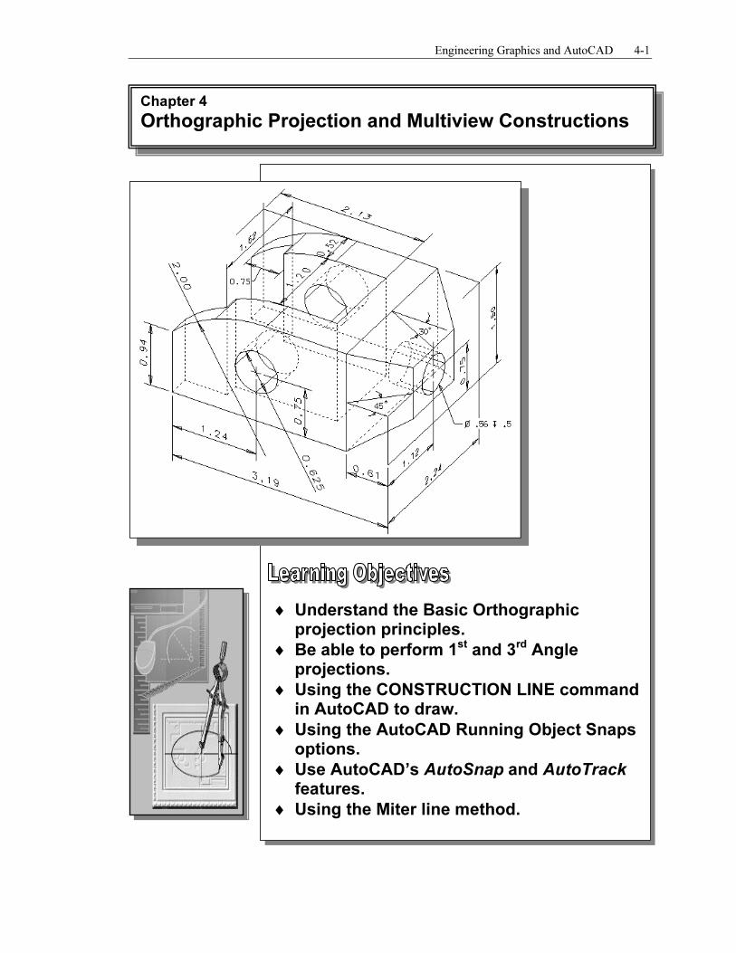
Most drawings produced and used in industry are multiview drawings. Multiview drawings are used to provide accurate three-dimensional object information on two-
dimensional media, a means of communicating all of the information necessary to transform an idea or concept into reality. The standards and conventions of multiview drawings have been developed over many years, which equip us with a universally understood method of communication.
Multiview drawings usually require several orthographic projections to define the shape of a three-dimensional object. Each orthographic view is a two-dimensional drawing showing only two of the three dimensions of the three-dimensional object. Consequently,
no individual view contains sufficient information to completely define the shape of the three-dimensional object. All orthographic views must be looked at together to comprehend the shape of the three-dimensional object. The arrangement and relationship between the views are therefore very important in multiview drawings. Before taking a more in-depth look into the multiview drawings, we will first look at the concepts and
principles of projections.
3D Object
Multiview drawing
(2D Views)
Orthographic Views and Multiview Constructions 4-3
Basic Principle of Projection
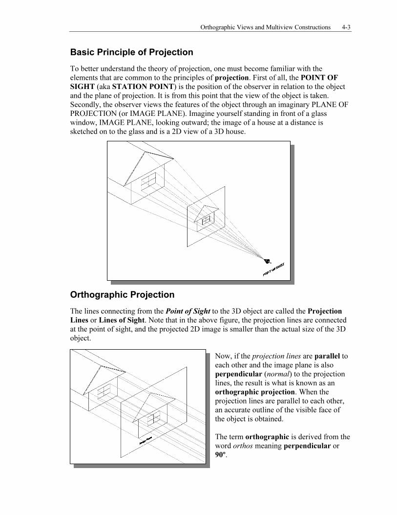
To better understand the theory of projection, one must become familiar with the elements that are common to the principles of projection. First of all, the POINT OF
SIGHT (aka STATION POINT) is the position of the observer in relation to the object and the plane of projection. It is from this point that the view of the object is taken. Secondly, the observer views the features of the object through an imaginary PLANE OF PROJECTION (or IMAGE PLANE). Imagine yourself standing in front of a glass window, IMAGE PLANE, looking outward; the image of a house at a distance is sketched on to the glass and is a 2D view of a 3D house.
Orthographic Projection
The lines connecting from the Point of Sight to the 3D object are called the Projection
Lines or Lines of Sight. Note that in the above figure, the projection lines are connected at the point of sight, and the projected 2D image is smaller than the actual size of the 3D object.
Now, if the projection lines are parallel to each other and the image plane is also
perpendicular (normal) to the projection lines, the result is what is known as an orthographic projection. When the projection lines are parallel to each other, an accurate outline of the visible face of
the object is obtained. The term orthographic is derived from the
word orthos meaning perpendicular or 90º.
4-4 Engineering Graphics and AutoCAD
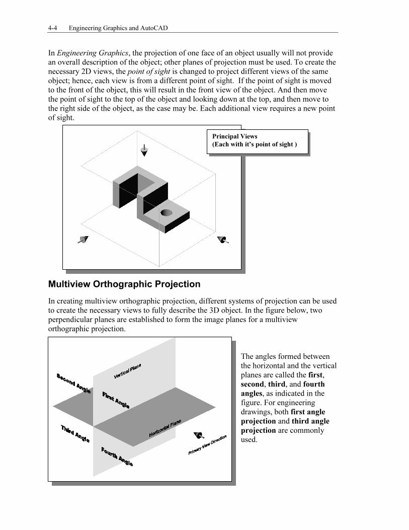
In Engineering Graphics, the projection of one face of an object usually will not provide an overall description of the object; other planes of projection must be used. To create the necessary 2D views, the point of sight is changed to project different views of the same object; hence, each view is from a different point of sight. If the point of sight is moved to the front of the object, this will result in the front view of the object. And then move the point of sight to the top of the object and looking down at the top, and then move to the right side of the object, as the case may be. Each additional view requires a new point of sight.
Multiview Orthographic Projection
In creating multiview orthographic projection, different systems of projection can be used to create the necessary views to fully describe the 3D object. In the figure below, two perpendicular planes are established to form the image planes for a multiview orthographic projection.
The angles formed between the horizontal and the vertical planes are called the first, second, third, and fourth
angles, as indicated in the figure. For engineering drawings, both first angle
projection and third angle
projection are commonly used.
Principal Views
(Each with it’s point of sight )
Orthographic Views and Multiview Constructions 4-5
FIRST-ANGLE PROJECTION
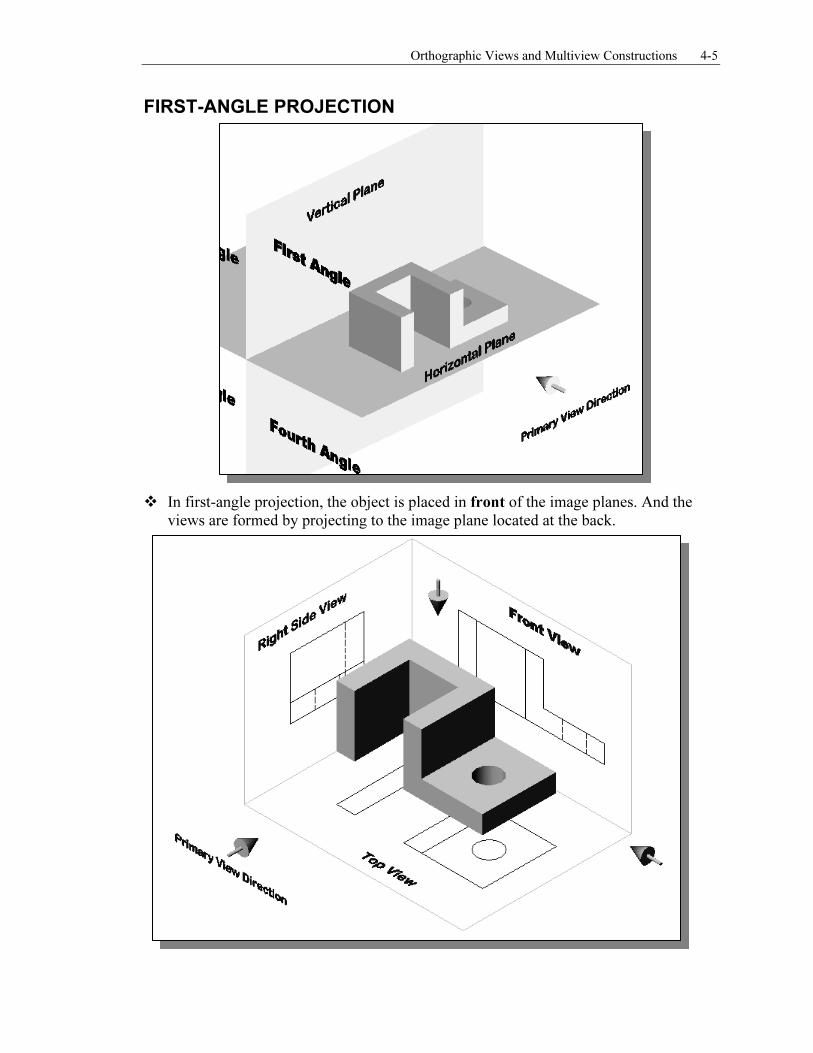
� In first-angle projection, the object is placed in front of the image planes. And the
views are formed by projecting to the image plane located at the back.
4-6 Engineering Graphics and AutoCAD
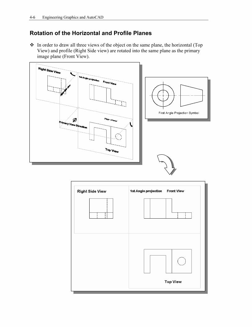
Rotation of the Horizontal and Profile Planes � In order to draw all three views of the object on the same plane, the horizontal (Top
View) and profile (Right Side view) are rotated into the same plane as the primary image plane (Front View).

Orthographic Views and Multiview Constructions 4-7
Getting the 3D Adjuster Model through the Internet
• AutoCAD® 2007 allows us to share files and resources through the Internet.
Drawings can be placed and opened to an Internet location, insert blocks by dragging drawings from a web site, and insert hyperlinks in drawings so that others can access related documents. Note that to use the AutoCAD® 2007 Internet features, Microsoft
Internet Explorer 6.0 (or a later version) and Internet or Intranet connections are required.
We will illustrate the procedure to open an AutoCAD file from the Internet by Uniform Resource Locator (URL).
1. Select the AutoCAD 2007 option on the Program menu or select the
AutoCAD 2007 icon on the Desktop.
2. In the AutoCAD Startup dialog box, select Open a Drawing with a single click of the left-mouse-button.
3. In the Select File dialog box, enter
http://www. sdcACAD.com/acad2007/Adjuster1stAngle.dwg as shown in the figure below.
4. Click the Open icon and the file is downloaded from the
www.sdcACAD.com web site to the local computer. � The URL entered must be of the Hypertext Transfer Protocol (http://) and the
complete filename must be entered including the filename extension (.dwg or .dwt).
4-8 Engineering Graphics and AutoCAD
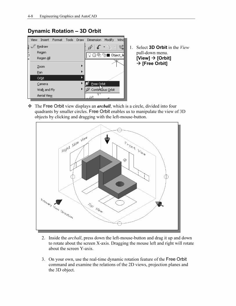
Dynamic Rotation – 3D Orbit
1. Select 3D Orbit in the View
pull-down menu.
[View] � [Orbit] � [Free Orbit]
� The Free Orbit view displays an arcball, which is a circle, divided into four
quadrants by smaller circles. Free Orbit enables us to manipulate the view of 3D objects by clicking and dragging with the left-mouse-button.
2. Inside the arcball, press down the left-mouse-button and drag it up and down
to rotate about the screen X-axis. Dragging the mouse left and right will rotate
about the screen Y-axis.
3. On your own, use the real-time dynamic rotation feature of the Free Orbit command and examine the relations of the 2D views, projection planes and
the 3D object.
Orthographic Views and Multiview Constructions 4-9
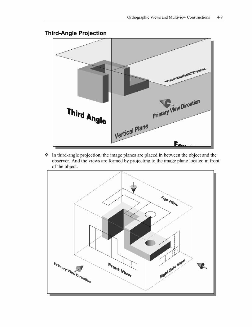
Third-Angle Projection
� In third-angle projection, the image planes are placed in between the object and the
observer. And the views are formed by projecting to the image plane located in front of the object.
4-10 Engineering Graphics and AutoCAD
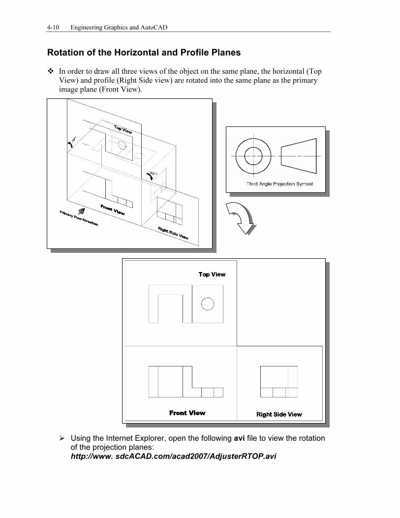
Rotation of the Horizontal and Profile Planes � In order to draw all three views of the object on the same plane, the horizontal (Top
View) and profile (Right Side view) are rotated into the same plane as the primary image plane (Front View).
� Using the Internet Explorer, open the following avi file to view the rotation
of the projection planes: http://www. sdcACAD.com/acad2007/AdjusterRTOP.avi
Orthographic Views and Multiview Constructions 4-11
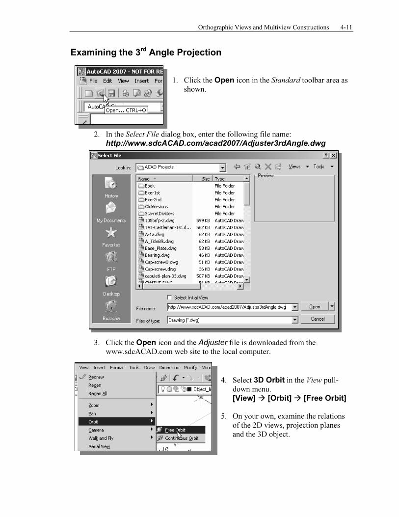
Examining the 3rd Angle Projection
1. Click the Open icon in the Standard toolbar area as shown.
2. In the Select File dialog box, enter the following file name:
http://www.sdcACAD.com/acad2007/Adjuster3rdAngle.dwg
3. Click the Open icon and the Adjuster file is downloaded from the www.sdcACAD.com web site to the local computer.
4. Select 3D Orbit in the View pull-down menu.
[View] � [Orbit] � [Free Orbit] 5. On your own, examine the relations
of the 2D views, projection planes and the 3D object.
4-12 Engineering Graphics and AutoCAD
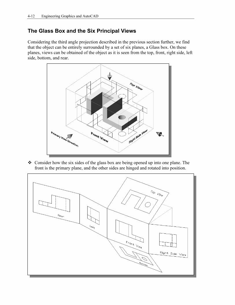
The Glass Box and the Six Principal Views Considering the third angle projection described in the previous section further, we find that the object can be entirely surrounded by a set of six planes, a Glass box. On these planes, views can be obtained of the object as it is seen from the top, front, right side, left side, bottom, and rear.
� Consider how the six sides of the glass box are being opened up into one plane. The
front is the primary plane, and the other sides are hinged and rotated into position.
Orthographic Views and Multiview Constructions 4-13
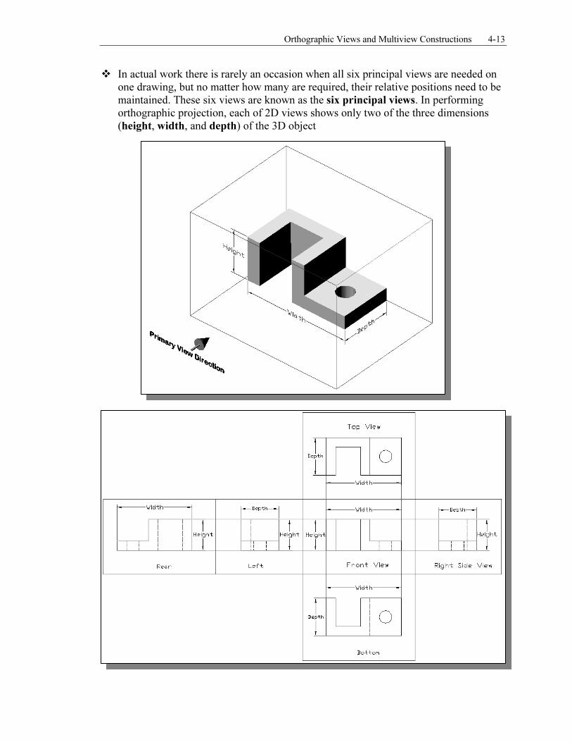
� In actual work there is rarely an occasion when all six principal views are needed on one drawing, but no matter how many are required, their relative positions need to be maintained. These six views are known as the six principal views. In performing orthographic projection, each of 2D views shows only two of the three dimensions (height, width, and depth) of the 3D object
4-14 Engineering Graphics and AutoCAD
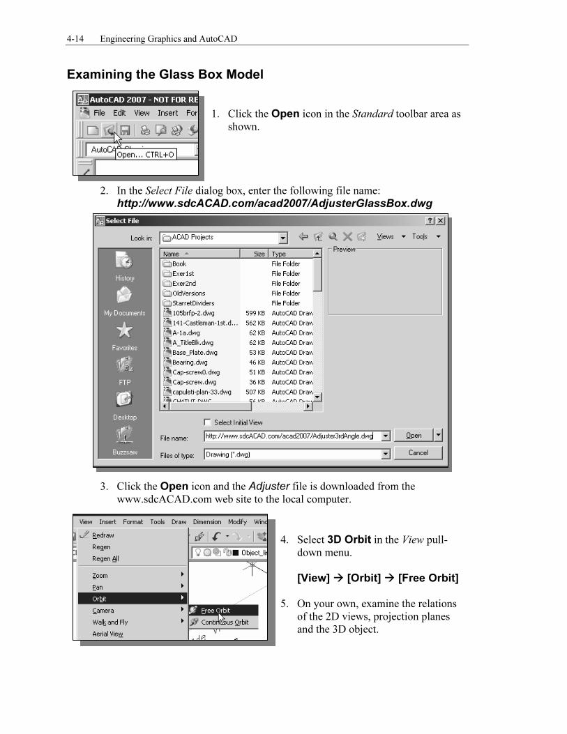
Examining the Glass Box Model
1. Click the Open icon in the Standard toolbar area as shown.
2. In the Select File dialog box, enter the following file name:
http://www.sdcACAD.com/acad2007/AdjusterGlassBox.dwg
3. Click the Open icon and the Adjuster file is downloaded from the www.sdcACAD.com web site to the local computer.
4. Select 3D Orbit in the View pull-down menu.
[View] � [Orbit] � [Free Orbit]
5. On your own, examine the relations of the 2D views, projection planes and the 3D object.
Orthographic Views and Multiview Constructions 4-15
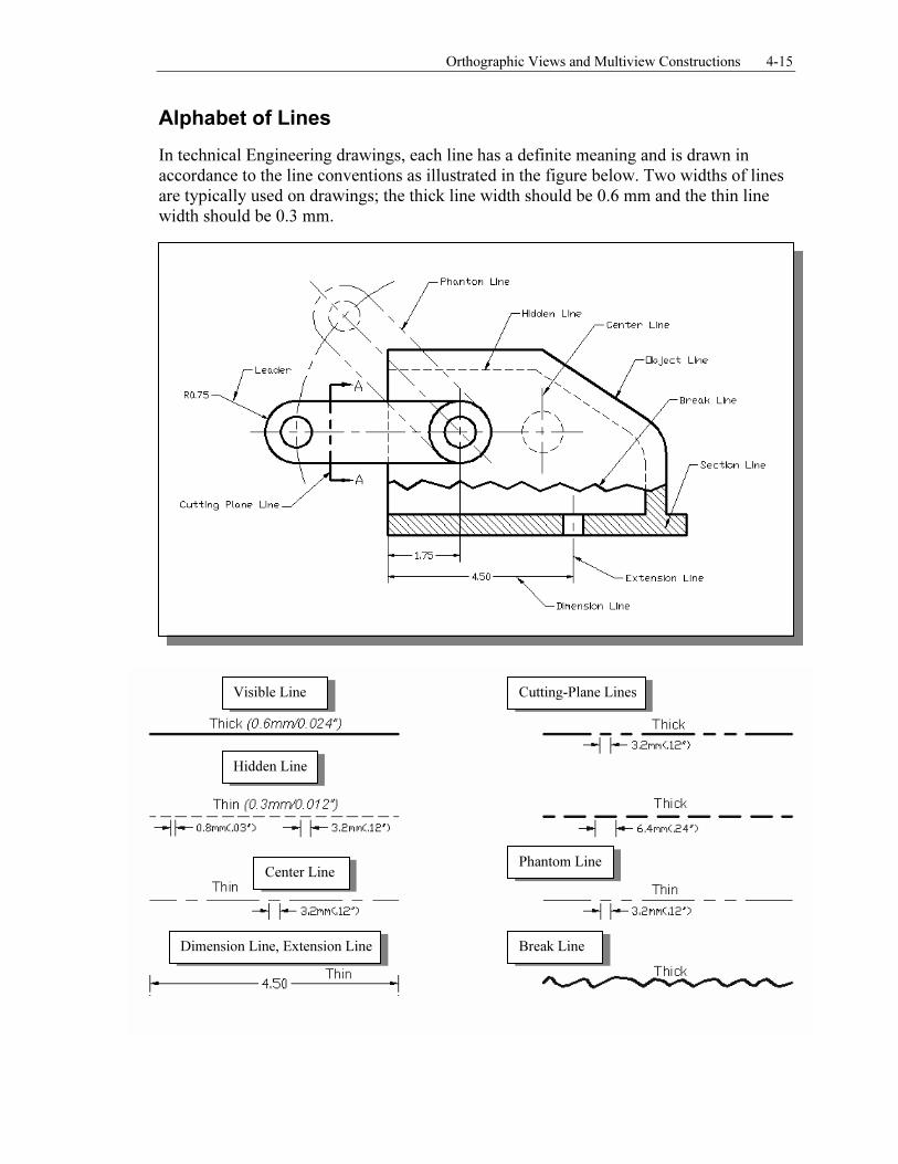
Alphabet of Lines
In technical Engineering drawings, each line has a definite meaning and is drawn in accordance to the line conventions as illustrated in the figure below. Two widths of lines are typically used on drawings; the thick line width should be 0.6 mm and the thin line width should be 0.3 mm.
Visible Line
Hidden Line
Cutting-Plane Lines
Center Line
Dimension Line, Extension Line
Phantom Line
Break Line
4-16 Engineering Graphics and AutoCAD
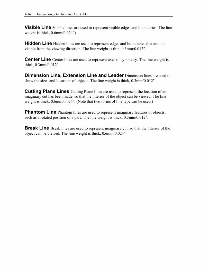
Visible Line Visible lines are used to represent visible edges and boundaries. The line
weight is thick, 0.6mm/0.024″).
Hidden Line Hidden lines are used to represent edges and boundaries that are not
visible from the viewing direction. The line weight is thin, 0.3mm/0.012″.
Center Line Center lines are used to represent axes of symmetry. The line weight is
thick, 0.3mm/0.012″.
Dimension Line, Extension Line and Leader Dimension lines are used to
show the sizes and locations of objects. The line weight is thick, 0.3mm/0.012″.
Cutting Plane Lines Cutting Plane lines are used to represent the location of an
imaginary cut has been made, so that the interior of the object can be viewed. The line
weight is thick, 0.6mm/0.024″. (Note that two forms of line type can be used.)
Phantom Line Phantom lines are used to represent imaginary features or objects,
such as a rotated position of a part. The line weight is thick, 0.3mm/0.012″.
Break Line Break lines are used to represent imaginary cut, so that the interior of the
object can be viewed. The line weight is thick, 0.6mm/0.024″.
Orthographic Views and Multiview Constructions 4-17
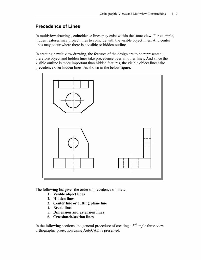
Precedence of Lines In multiview drawings, coincidence lines may exist within the same view. For example, hidden features may project lines to coincide with the visible object lines. And center lines may occur where there is a visible or hidden outline. In creating a multiview drawing, the features of the design are to be represented, therefore object and hidden lines take precedence over all other lines. And since the visible outline is more important than hidden features, the visible object lines take precedence over hidden lines. As shown in the below figure.
The following list gives the order of precedence of lines:
1. Visible object lines
2. Hidden lines
3. Center line or cutting plane line
4. Break lines
5. Dimension and extension lines
6. Crosshatch/section lines
In the following sections, the general procedure of creating a 3rd
angle three-view orthographic projection using AutoCAD is presented.
4-18 Engineering Graphics and AutoCAD
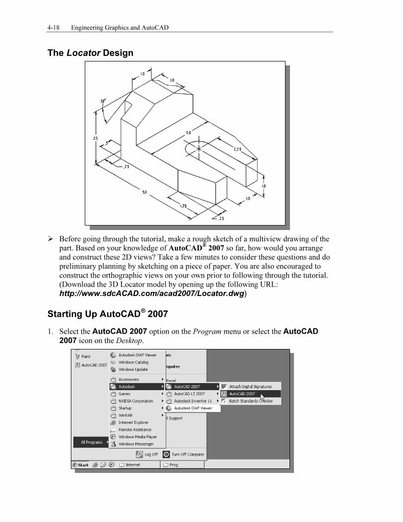
The Locator Design
� Before going through the tutorial, make a rough sketch of a multiview drawing of the
part. Based on your knowledge of AutoCAD® 2007 so far, how would you arrange
and construct these 2D views? Take a few minutes to consider these questions and do preliminary planning by sketching on a piece of paper. You are also encouraged to construct the orthographic views on your own prior to following through the tutorial. (Download the 3D Locator model by opening up the following URL:
http://www.sdcACAD.com/acad2007/Locator.dwg)
Starting Up AutoCAD® 2007
1. Select the AutoCAD 2007 option on the Program menu or select the AutoCAD 2007 icon on the Desktop.
Orthographic Views and Multiview Constructions 4-19
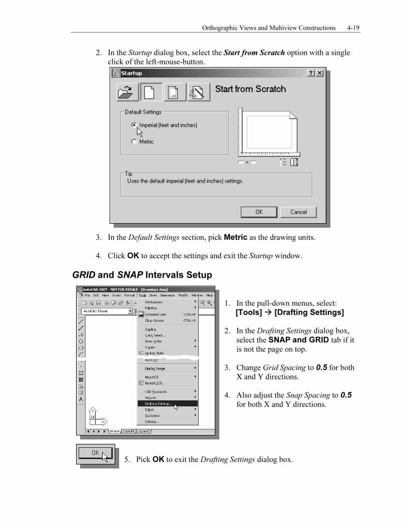
2. In the Startup dialog box, select the Start from Scratch option with a single click of the left-mouse-button.
3. In the Default Settings section, pick Metric as the drawing units.
4. Click OK to accept the settings and exit the Startup window.
GRID and SNAP Intervals Setup
1. In the pull-down menus, select:
[Tools] � [Drafting Settings] 2. In the Drafting Settings dialog box,
select the SNAP and GRID tab if it is not the page on top.
3. Change Grid Spacing to 0.5 for both X and Y directions.
4. Also adjust the Snap Spacing to 0.5
for both X and Y directions.
5. Pick OK to exit the Drafting Settings dialog box.
Metric
4-20 Engineering Graphics and AutoCAD
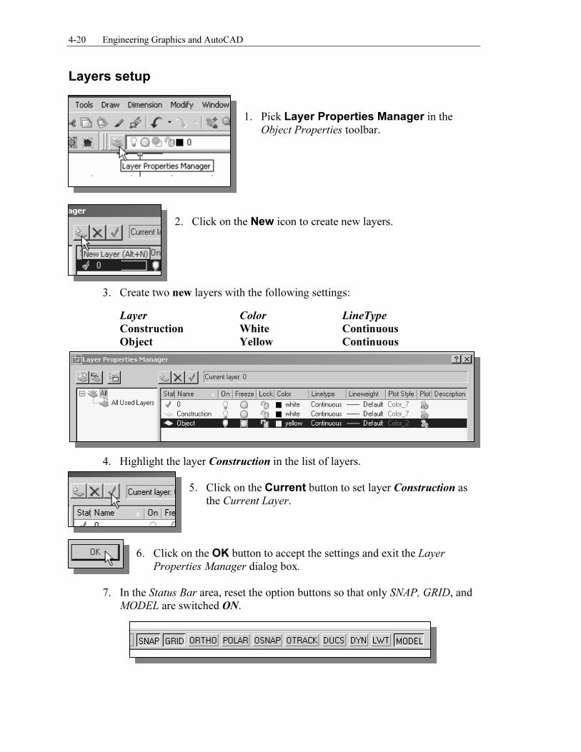
Layers setup
1. Pick Layer Properties Manager in the Object Properties toolbar.
2. Click on the New icon to create new layers.
3. Create two new layers with the following settings:
Layer Color LineType
Construction White Continuous
Object Yellow Continuous
4. Highlight the layer Construction in the list of layers.
5. Click on the Current button to set layer Construction as the Current Layer.
6. Click on the OK button to accept the settings and exit the Layer
Properties Manager dialog box.
7. In the Status Bar area, reset the option buttons so that only SNAP, GRID, and MODEL are switched ON.
Orthographic Views and Multiview Constructions 4-21
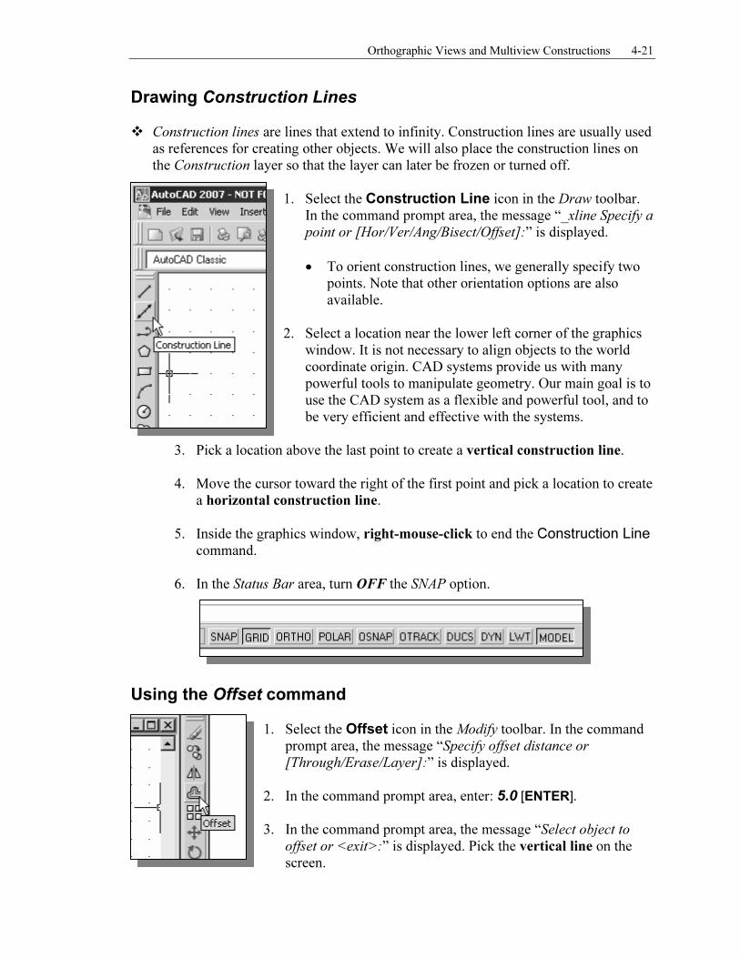
Drawing Construction Lines � Construction lines are lines that extend to infinity. Construction lines are usually used
as references for creating other objects. We will also place the construction lines on the Construction layer so that the layer can later be frozen or turned off.
1. Select the Construction Line icon in the Draw toolbar. In the command prompt area, the message “_xline Specify a
point or [Hor/Ver/Ang/Bisect/Offset]:” is displayed.
• To orient construction lines, we generally specify two points. Note that other orientation options are also available.
2. Select a location near the lower left corner of the graphics
window. It is not necessary to align objects to the world coordinate origin. CAD systems provide us with many powerful tools to manipulate geometry. Our main goal is to use the CAD system as a flexible and powerful tool, and to be very efficient and effective with the systems.
3. Pick a location above the last point to create a vertical construction line.
4. Move the cursor toward the right of the first point and pick a location to create
a horizontal construction line.
5. Inside the graphics window, right-mouse-click to end the Construction Line
command.
6. In the Status Bar area, turn OFF the SNAP option.
Using the Offset command
1. Select the Offset icon in the Modify toolbar. In the command prompt area, the message “Specify offset distance or
[Through/Erase/Layer]:” is displayed.
2. In the command prompt area, enter: 5.0 [ENTER].
3. In the command prompt area, the message “Select object to
offset or <exit>:” is displayed. Pick the vertical line on the screen.
4-22 Engineering Graphics and AutoCAD
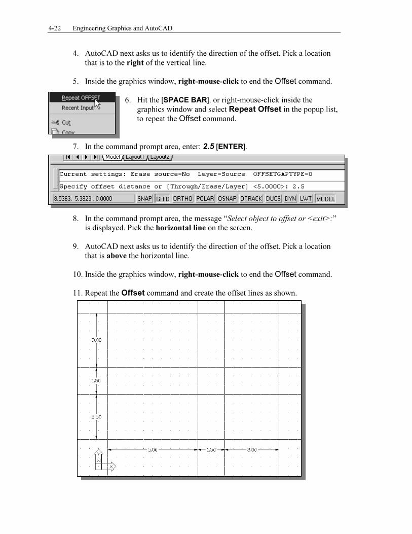
4. AutoCAD next asks us to identify the direction of the offset. Pick a location that is to the right of the vertical line.
5. Inside the graphics window, right-mouse-click to end the Offset command. 6. Hit the [SPACE BAR], or right-mouse-click inside the
graphics window and select Repeat Offset in the popup list,
to repeat the Offset command.
7. In the command prompt area, enter: 2.5 [ENTER].
8. In the command prompt area, the message “Select object to offset or <exit>:”
is displayed. Pick the horizontal line on the screen.
9. AutoCAD next asks us to identify the direction of the offset. Pick a location that is above the horizontal line.
10. Inside the graphics window, right-mouse-click to end the Offset command.
11. Repeat the Offset command and create the offset lines as shown.
Orthographic Views and Multiview Constructions 4-23
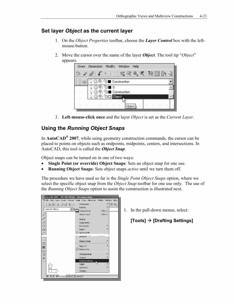
Set layer Object as the current layer
1. On the Object Properties toolbar, choose the Layer Control box with the left-mouse-button.
2. Move the cursor over the name of the layer Object. The tool tip “Object” appears.
3. Left-mouse-click once and the layer Object is set as the Current Layer.
Using the Running Object Snaps
In AutoCAD® 2007, while using geometry construction commands, the cursor can be
placed to points on objects such as endpoints, midpoints, centers, and intersections. In AutoCAD, this tool is called the Object Snap.
Object snaps can be turned on in one of two ways:
• Single Point (or override) Object Snaps: Sets an object snap for one use.
• Running Object Snaps: Sets object snaps active until we turn them off.
The procedure we have used so far is the Single Point Object Snaps option, where we select the specific object snap from the Object Snap toolbar for one use only. The use of the Running Object Snaps option to assist the construction is illustrated next.
1. In the pull-down menus, select:
[Tools] � [Drafting Settings]
4-24 Engineering Graphics and AutoCAD
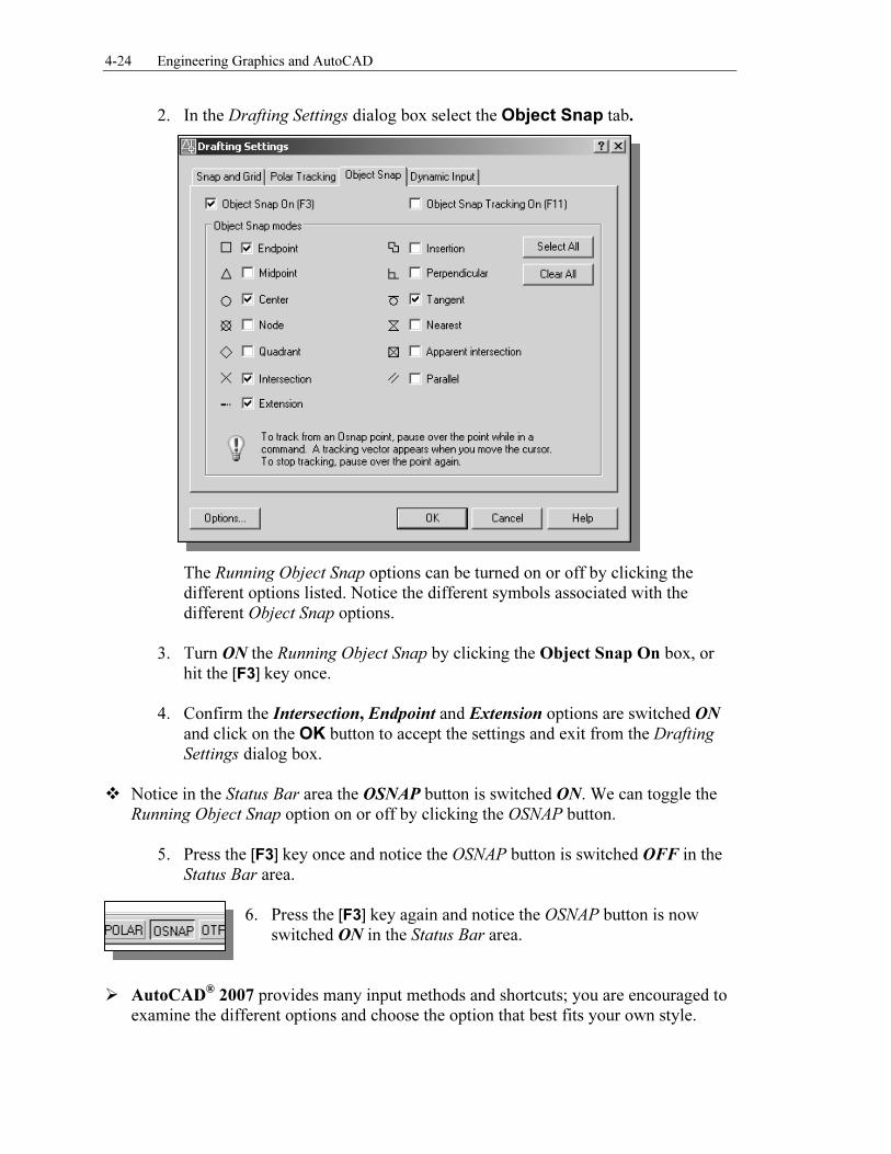
2. In the Drafting Settings dialog box select the Object Snap tab.
The Running Object Snap options can be turned on or off by clicking the different options listed. Notice the different symbols associated with the different Object Snap options.
3. Turn ON the Running Object Snap by clicking the Object Snap On box, or
hit the [F3] key once. 4. Confirm the Intersection, Endpoint and Extension options are switched ON
and click on the OK button to accept the settings and exit from the Drafting
Settings dialog box.
� Notice in the Status Bar area the OSNAP button is switched ON. We can toggle the Running Object Snap option on or off by clicking the OSNAP button.
5. Press the [F3] key once and notice the OSNAP button is switched OFF in the Status Bar area.
6. Press the [F3] key again and notice the OSNAP button is now
switched ON in the Status Bar area.
� AutoCAD
® 2007 provides many input methods and shortcuts; you are encouraged to
examine the different options and choose the option that best fits your own style.
Orthographic Views and Multiview Constructions 4-25
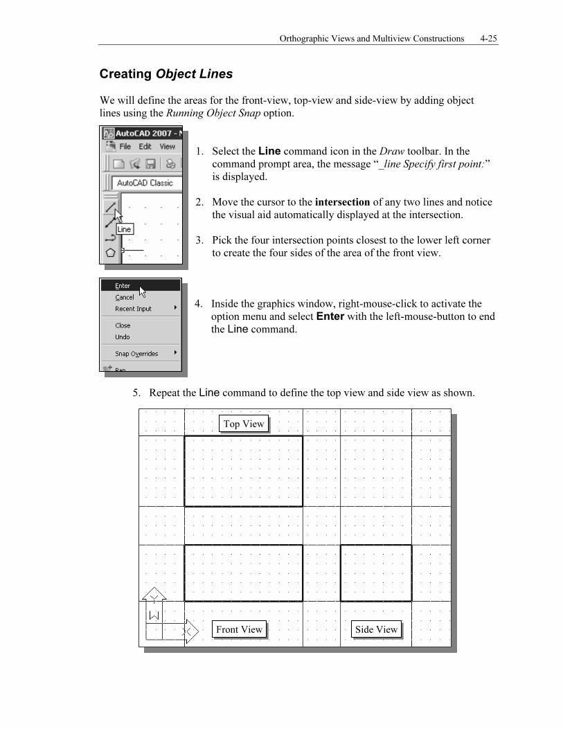
Creating Object Lines We will define the areas for the front-view, top-view and side-view by adding object lines using the Running Object Snap option.
1. Select the Line command icon in the Draw toolbar. In the command prompt area, the message “_line Specify first point:” is displayed.
2. Move the cursor to the intersection of any two lines and notice the visual aid automatically displayed at the intersection.
3. Pick the four intersection points closest to the lower left corner to create the four sides of the area of the front view.
4. Inside the graphics window, right-mouse-click to activate the
option menu and select Enter with the left-mouse-button to end
the Line command.
5. Repeat the Line command to define the top view and side view as shown.
Top View
Front View Side View
4-26 Engineering Graphics and AutoCAD
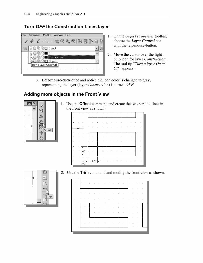
Turn OFF the Construction Lines layer 1. On the Object Properties toolbar,
choose the Layer Control box with the left-mouse-button.
2. Move the cursor over the light-
bulb icon for layer Construction. The tool tip “Turn a layer On or
Off” appears.
3. Left-mouse-click once and notice the icon color is changed to gray, representing the layer (layer Construction) is turned OFF.
Adding more objects in the Front View
1. Use the Offset command and create the two parallel lines in the front view as shown.
2. Use the Trim command and modify the front view as shown.
Orthographic Views and Multiview Constructions 4-27
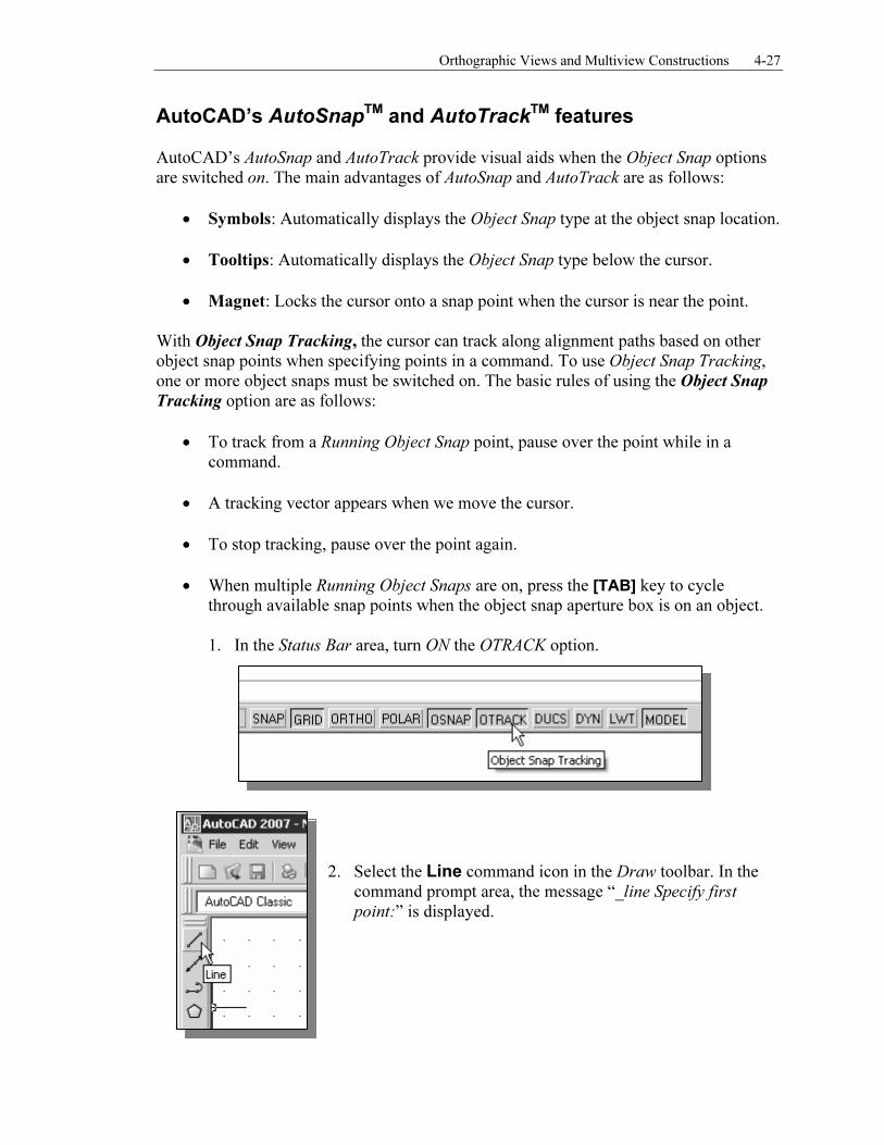
AutoCAD’s AutoSnapTM and AutoTrackTM features AutoCAD’s AutoSnap and AutoTrack provide visual aids when the Object Snap options are switched on. The main advantages of AutoSnap and AutoTrack are as follows:
• Symbols: Automatically displays the Object Snap type at the object snap location.
• Tooltips: Automatically displays the Object Snap type below the cursor.
• Magnet: Locks the cursor onto a snap point when the cursor is near the point. With Object Snap Tracking, the cursor can track along alignment paths based on other object snap points when specifying points in a command. To use Object Snap Tracking, one or more object snaps must be switched on. The basic rules of using the Object Snap
Tracking option are as follows:
• To track from a Running Object Snap point, pause over the point while in a command.
• A tracking vector appears when we move the cursor.
• To stop tracking, pause over the point again.
• When multiple Running Object Snaps are on, press the [TAB] key to cycle through available snap points when the object snap aperture box is on an object.
1. In the Status Bar area, turn ON the OTRACK option.
2. Select the Line command icon in the Draw toolbar. In the command prompt area, the message “_line Specify first
point:” is displayed.
4-28 Engineering Graphics and AutoCAD
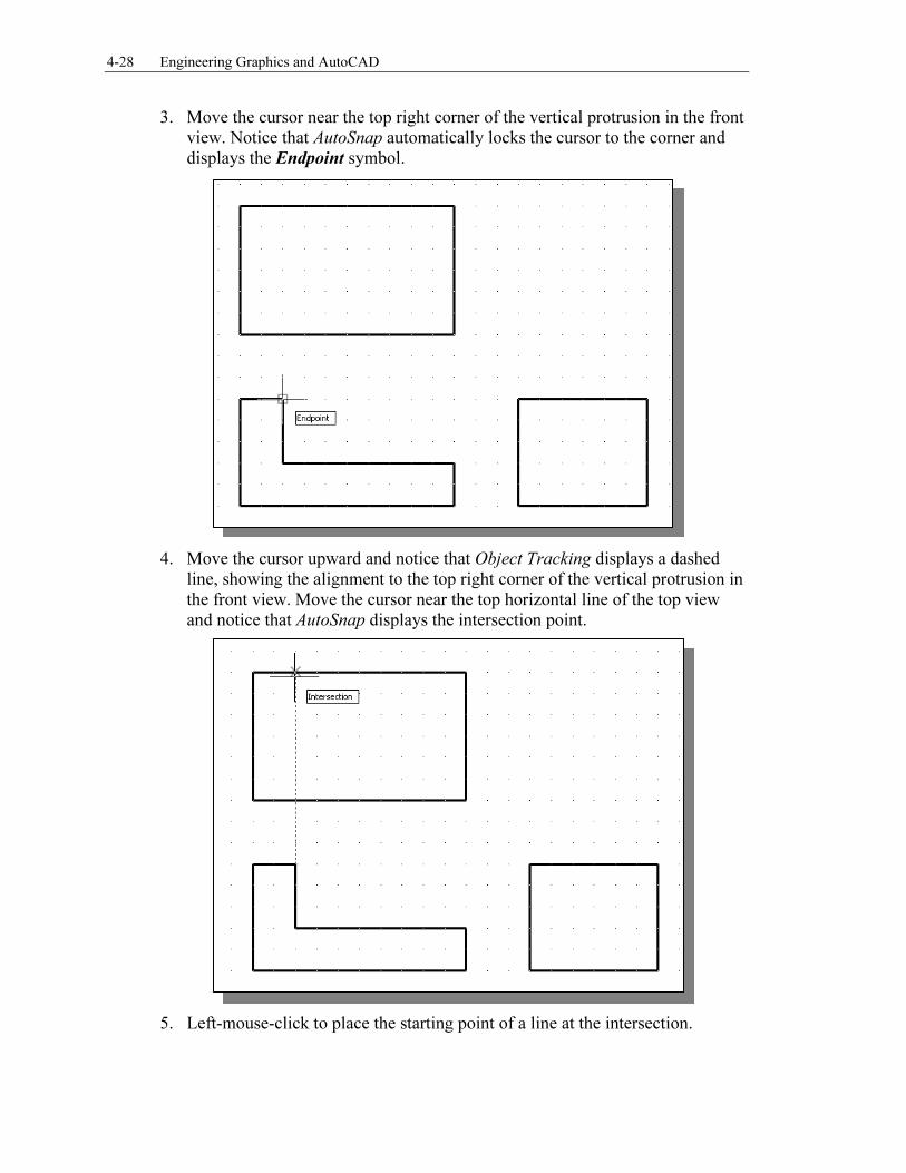
3. Move the cursor near the top right corner of the vertical protrusion in the front view. Notice that AutoSnap automatically locks the cursor to the corner and displays the Endpoint symbol.
4. Move the cursor upward and notice that Object Tracking displays a dashed
line, showing the alignment to the top right corner of the vertical protrusion in the front view. Move the cursor near the top horizontal line of the top view and notice that AutoSnap displays the intersection point.
5. Left-mouse-click to place the starting point of a line at the intersection.
Orthographic Views and Multiview Constructions 4-29
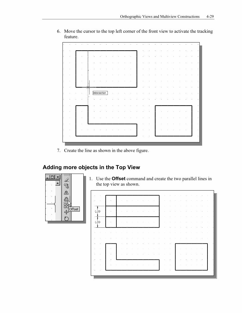
6. Move the cursor to the top left corner of the front view to activate the tracking feature.
7. Create the line as shown in the above figure.
Adding more objects in the Top View
1. Use the Offset command and create the two parallel lines in the top view as shown.
4-30 Engineering Graphics and AutoCAD
2. Move the cursor to the Standard toolbar area and right-mouse-click on any icon to display a list of toolbar menu groups.
3. Select Object Snap, with the left-mouse-button, to display the Object Snap
toolbar on the screen.
4. Select the Line command icon in the Draw toolbar. In the command prompt area, the message “_line Specify first point:” is displayed.
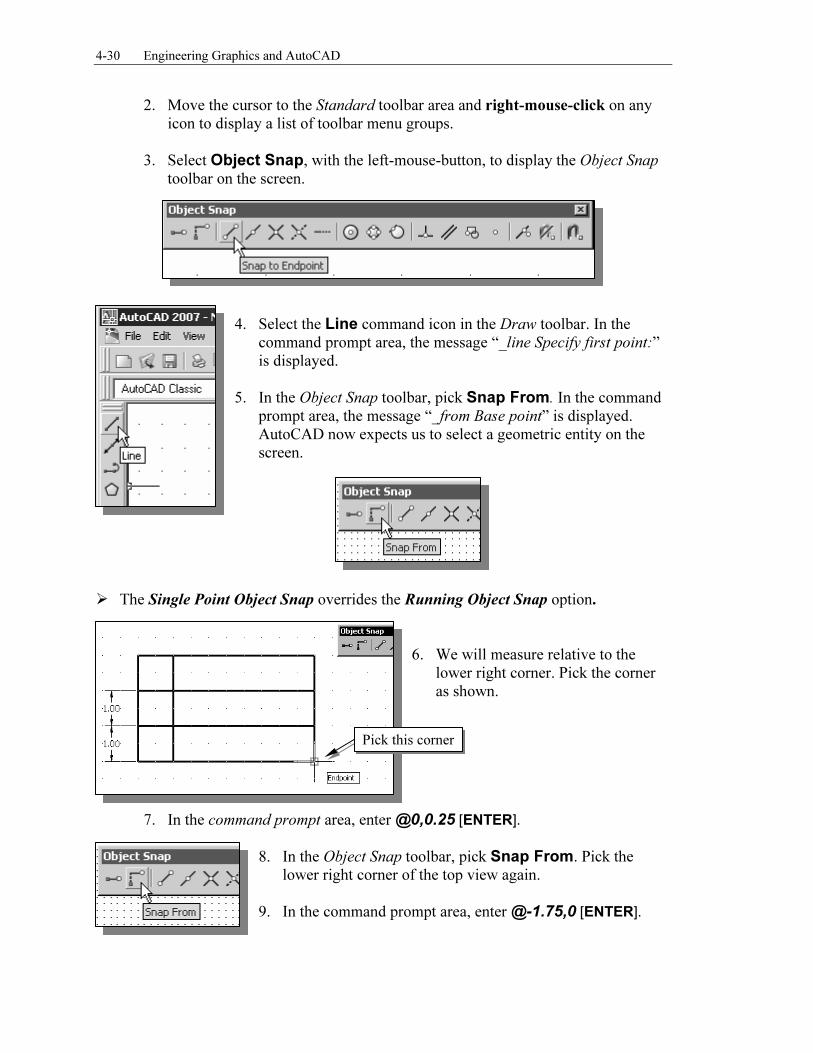
5. In the Object Snap toolbar, pick Snap From. In the command prompt area, the message “_from Base point” is displayed. AutoCAD now expects us to select a geometric entity on the screen.
� The Single Point Object Snap overrides the Running Object Snap option.
6. We will measure relative to the
lower right corner. Pick the corner as shown.
7. In the command prompt area, enter @0,0.25 [ENTER].
8. In the Object Snap toolbar, pick Snap From. Pick the lower right corner of the top view again.
9. In the command prompt area, enter @-1.75,0 [ENTER].
Pick this corner
Orthographic Views and Multiview Constructions 4-31
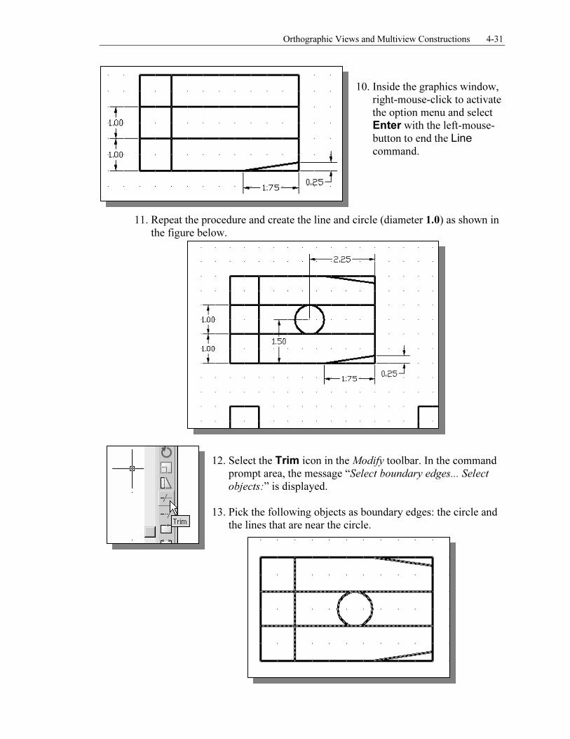
10. Inside the graphics window,
right-mouse-click to activate the option menu and select
Enter with the left-mouse-
button to end the Line
command.
11. Repeat the procedure and create the line and circle (diameter 1.0) as shown in
the figure below.
12. Select the Trim icon in the Modify toolbar. In the command prompt area, the message “Select boundary edges... Select
objects:” is displayed. 13. Pick the following objects as boundary edges: the circle and
the lines that are near the circle.
4-32 Engineering Graphics and AutoCAD
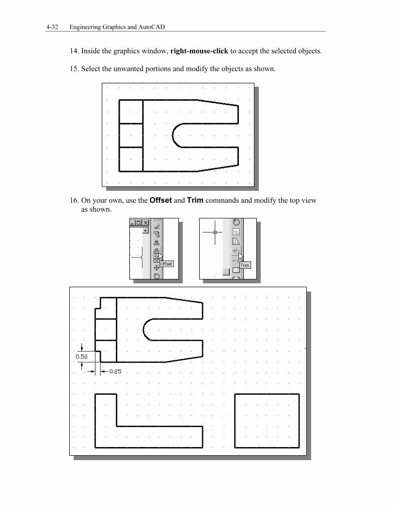
14. Inside the graphics window, right-mouse-click to accept the selected objects. 15. Select the unwanted portions and modify the objects as shown.
16. On your own, use the Offset and Trim commands and modify the top view as shown.
Orthographic Views and Multiview Constructions 4-33
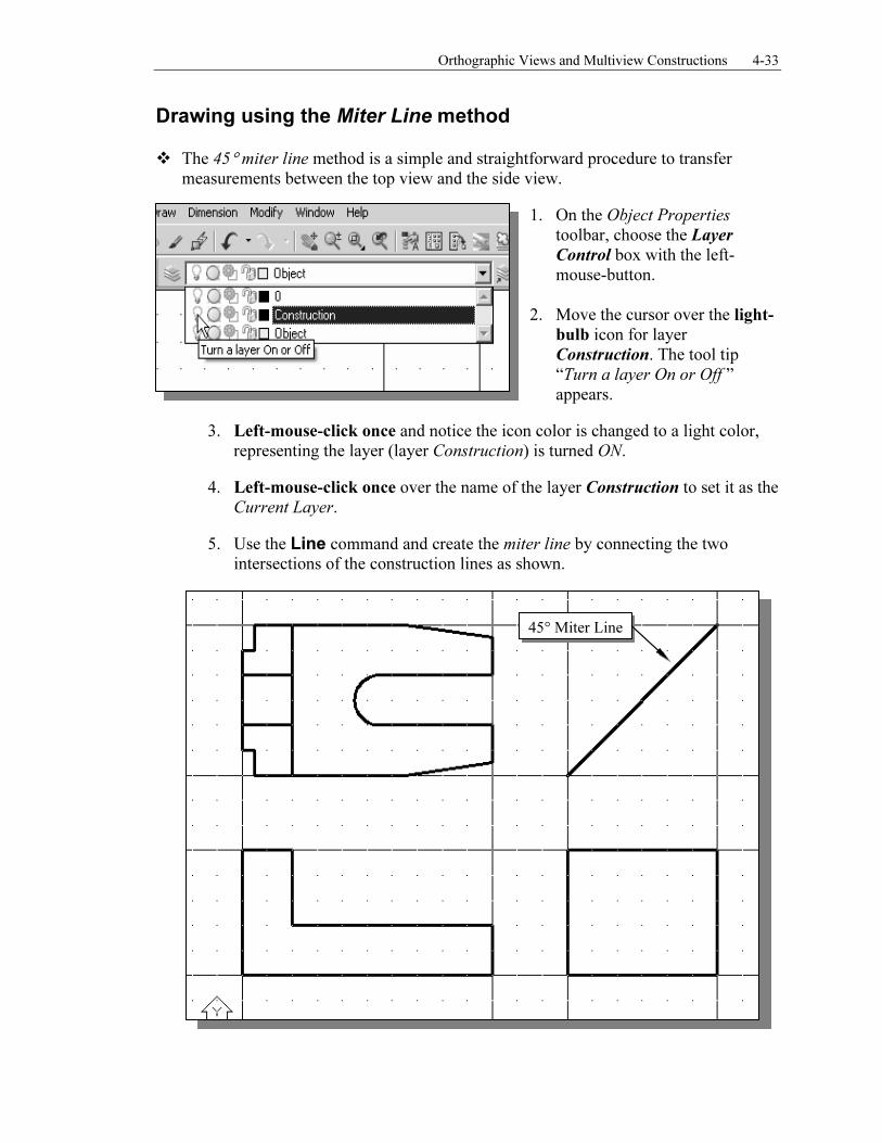
Drawing using the Miter Line method
� The 45° miter line method is a simple and straightforward procedure to transfer measurements between the top view and the side view.
1. On the Object Properties
toolbar, choose the Layer
Control box with the left-mouse-button.
2. Move the cursor over the light-
bulb icon for layer Construction. The tool tip “Turn a layer On or Off ” appears.
3. Left-mouse-click once and notice the icon color is changed to a light color, representing the layer (layer Construction) is turned ON.
4. Left-mouse-click once over the name of the layer Construction to set it as the Current Layer.
5. Use the Line command and create the miter line by connecting the two intersections of the construction lines as shown.
45° Miter Line
4-34 Engineering Graphics and AutoCAD
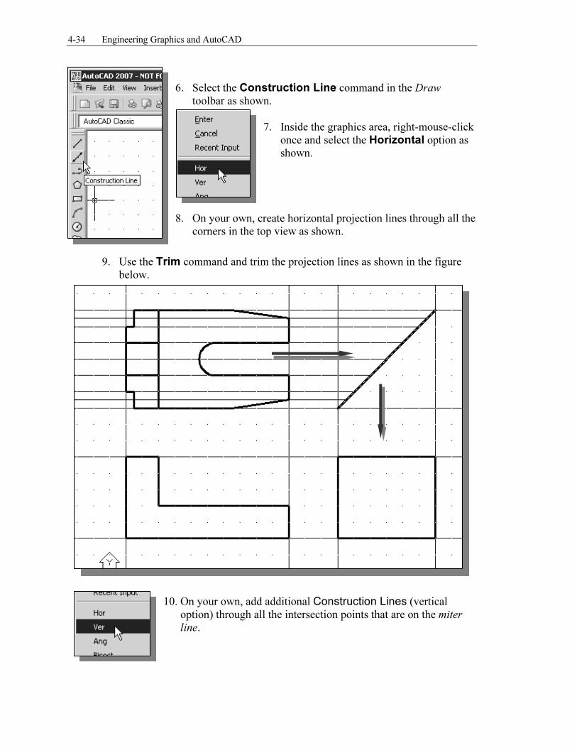
6. Select the Construction Line command in the Draw toolbar as shown.
7. Inside the graphics area, right-mouse-click
once and select the Horizontal option as shown.
8. On your own, create horizontal projection lines through all the
corners in the top view as shown.
9. Use the Trim command and trim the projection lines as shown in the figure below.
10. On your own, add additional Construction Lines (vertical option) through all the intersection points that are on the miter
line.
Orthographic Views and Multiview Constructions 4-35
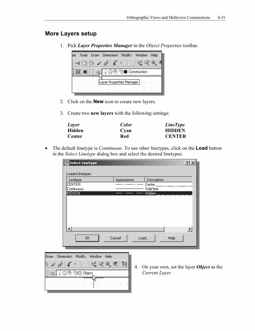
More Layers setup
1. Pick Layer Properties Manager in the Object Properties toolbar.
2. Click on the New icon to create new layers. 3. Create two new layers with the following settings:
Layer Color LineType
Hidden Cyan HIDDEN
Center Red CENTER
• The default linetype is Continuous. To use other linetypes, click on the Load button in the Select Linetype dialog box and select the desired linetypes.
4. On your own, set the layer Object as the
Current Layer.
4-36 Engineering Graphics and AutoCAD
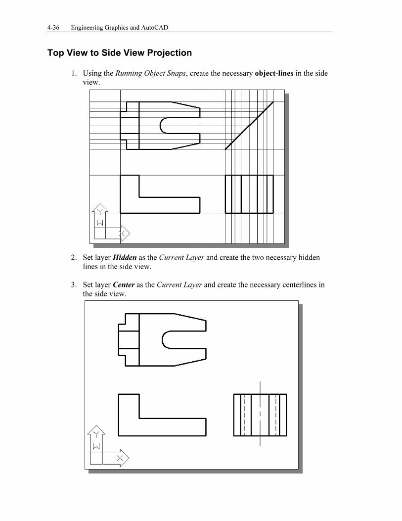
Top View to Side View Projection
1. Using the Running Object Snaps, create the necessary object-lines in the side view.
2. Set layer Hidden as the Current Layer and create the two necessary hidden
lines in the side view.
3. Set layer Center as the Current Layer and create the necessary centerlines in the side view.
Orthographic Views and Multiview Constructions 4-37
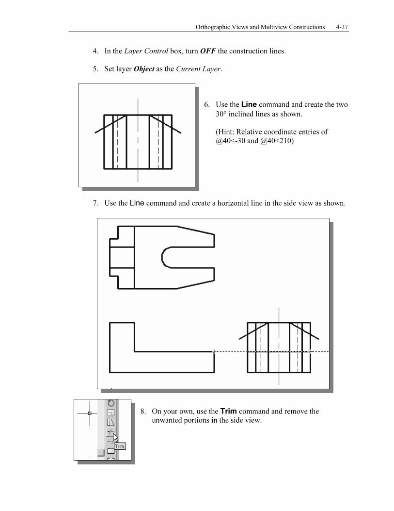
4. In the Layer Control box, turn OFF the construction lines.
5. Set layer Object as the Current Layer.
6. Use the Line command and create the two
30° inclined lines as shown. (Hint: Relative coordinate entries of @40<-30 and @40<210)
7. Use the Line command and create a horizontal line in the side view as shown.
8. On your own, use the Trim command and remove the unwanted portions in the side view.
4-38 Engineering Graphics and AutoCAD
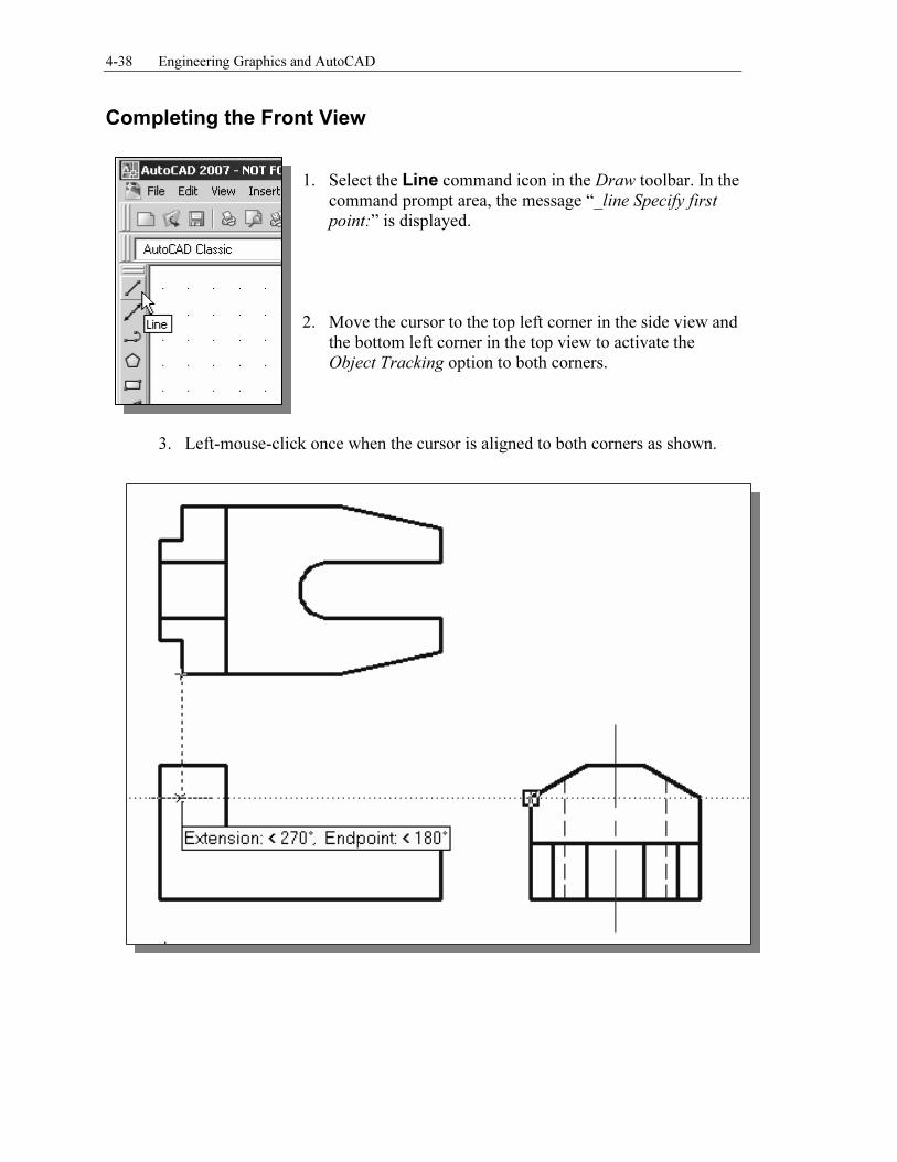
Completing the Front View
1. Select the Line command icon in the Draw toolbar. In the command prompt area, the message “_line Specify first
point:” is displayed. 2. Move the cursor to the top left corner in the side view and
the bottom left corner in the top view to activate the Object Tracking option to both corners.
3. Left-mouse-click once when the cursor is aligned to both corners as shown.
Orthographic Views and Multiview Constructions 4-39
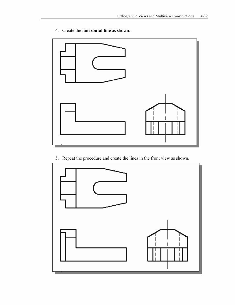
4. Create the horizontal line as shown.
5. Repeat the procedure and create the lines in the front view as shown.
4-40 Engineering Graphics and AutoCAD
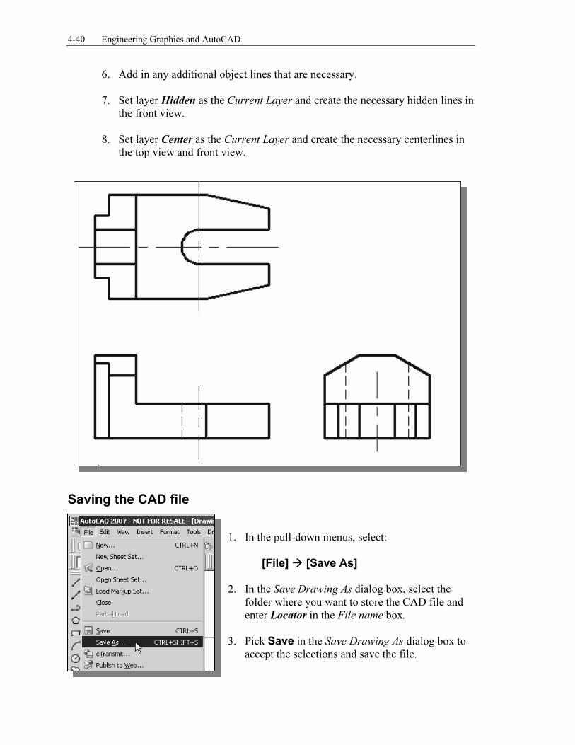
6. Add in any additional object lines that are necessary.
7. Set layer Hidden as the Current Layer and create the necessary hidden lines in the front view.
8. Set layer Center as the Current Layer and create the necessary centerlines in
the top view and front view.
Saving the CAD file
1. In the pull-down menus, select:
[File] � [Save As]
2. In the Save Drawing As dialog box, select the folder where you want to store the CAD file and
enter Locator in the File name box.
3. Pick Save in the Save Drawing As dialog box to accept the selections and save the file.
Orthographic Views and Multiview Constructions 4-41
Questions:
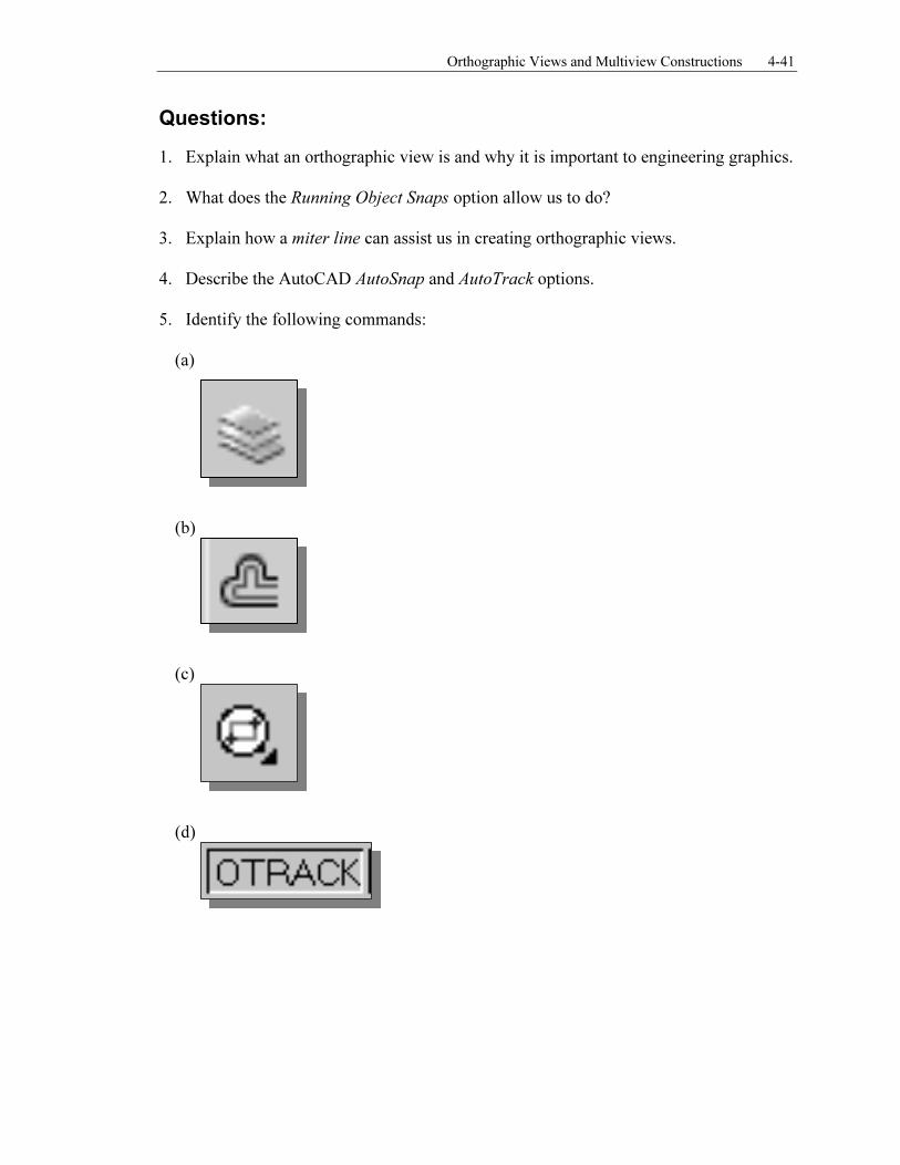
1. Explain what an orthographic view is and why it is important to engineering graphics. 2. What does the Running Object Snaps option allow us to do? 3. Explain how a miter line can assist us in creating orthographic views. 4. Describe the AutoCAD AutoSnap and AutoTrack options. 5. Identify the following commands:
(a)
(b)
(c)
(d)
4-42 Engineering Graphics and AutoCAD
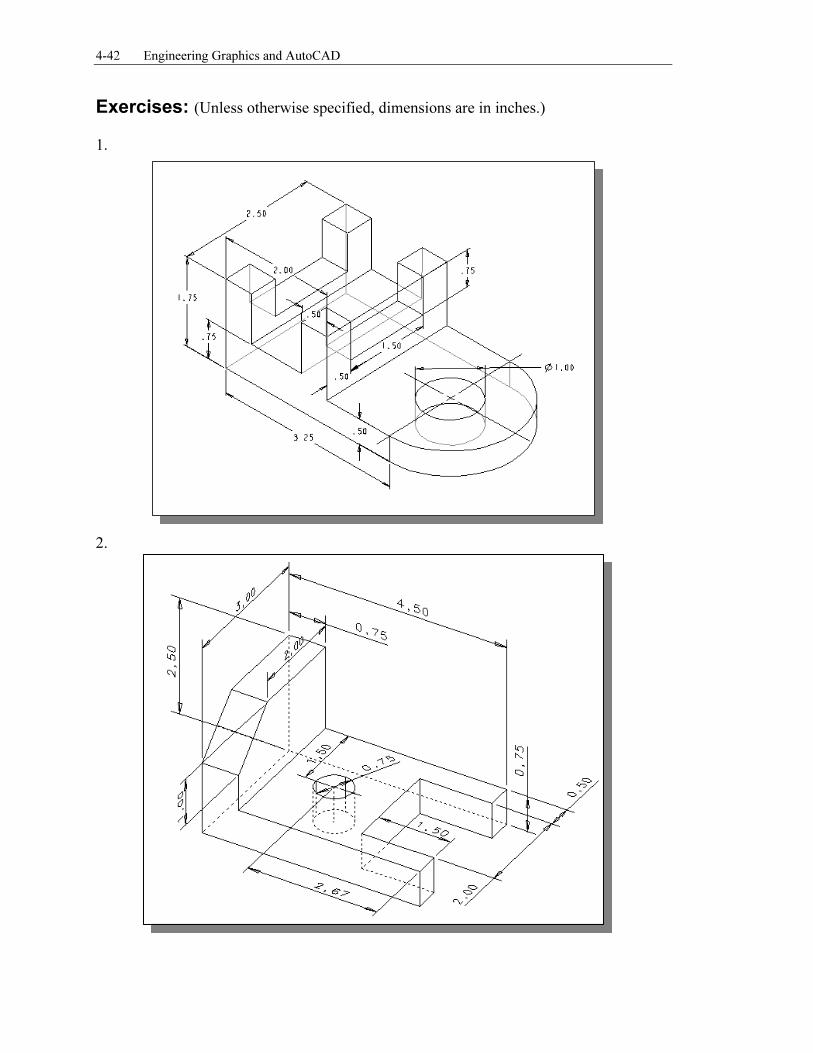
Exercises: (Unless otherwise specified, dimensions are in inches.) 1.
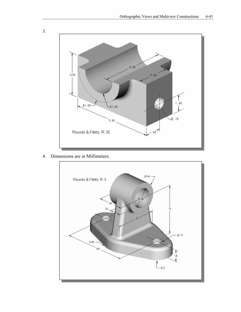
2.
Orthographic Views and Multiview Constructions 4-43
3.
4. Dimensions are in Millimeters.
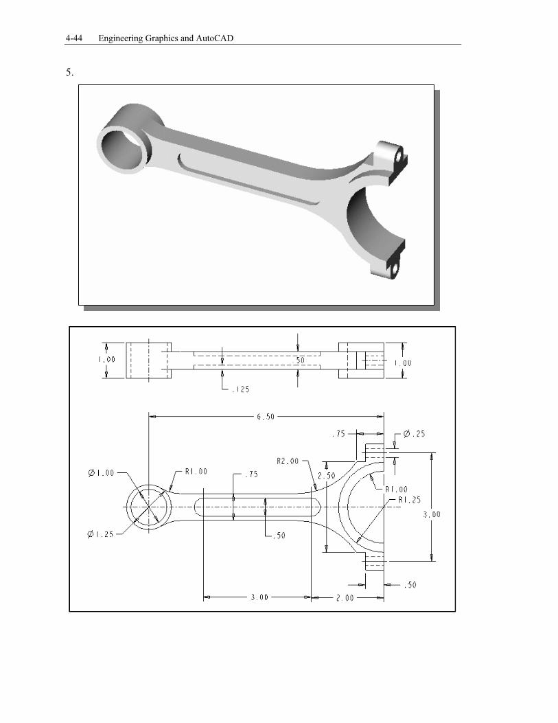
4-44 Engineering Graphics and AutoCAD
5.


![lecture11-ch5 [호환 모드]dis.dankook.ac.kr/lectures/cg12/wp-content/uploads/sites/... · 2015. 4. 21. · Orthographic Projection 다중관측직교투영(Multiview Orthographic](https://static.fdocuments.in/doc/165x107/5feee80a51ae05482f045e83/lecture11-ch5-eeoedis-2015-4-21-orthographic-projection-eeemultiview.jpg)