Chapter 4 Network Layer - Western Illinois Universityfaculty.wiu.edu/Y-Kim2/TM322ch4.pdf · Network...
126
Network Layer 4-1 Chapter 4 Network Layer
Transcript of Chapter 4 Network Layer - Western Illinois Universityfaculty.wiu.edu/Y-Kim2/TM322ch4.pdf · Network...
Network Layer 4-1
Chapter 4Network Layer

Network Layer 4-2
Network layertransport segment from sending to receiving host on sending side encapsulates segments into datagramson rcving side, delivers segments to transport layernetwork layer protocols in every host, routerrouter examines header fields in all IP datagrams passing through it
applicationtransportnetworkdata linkphysical
applicationtransportnetworkdata linkphysical
networkdata linkphysical network
data linkphysical
networkdata linkphysical
networkdata linkphysical
networkdata linkphysical
networkdata linkphysical
networkdata linkphysical
networkdata linkphysical
networkdata linkphysical
networkdata linkphysicalnetwork
data linkphysical

Network Layer 4-3
Two Key Network-Layer Functions
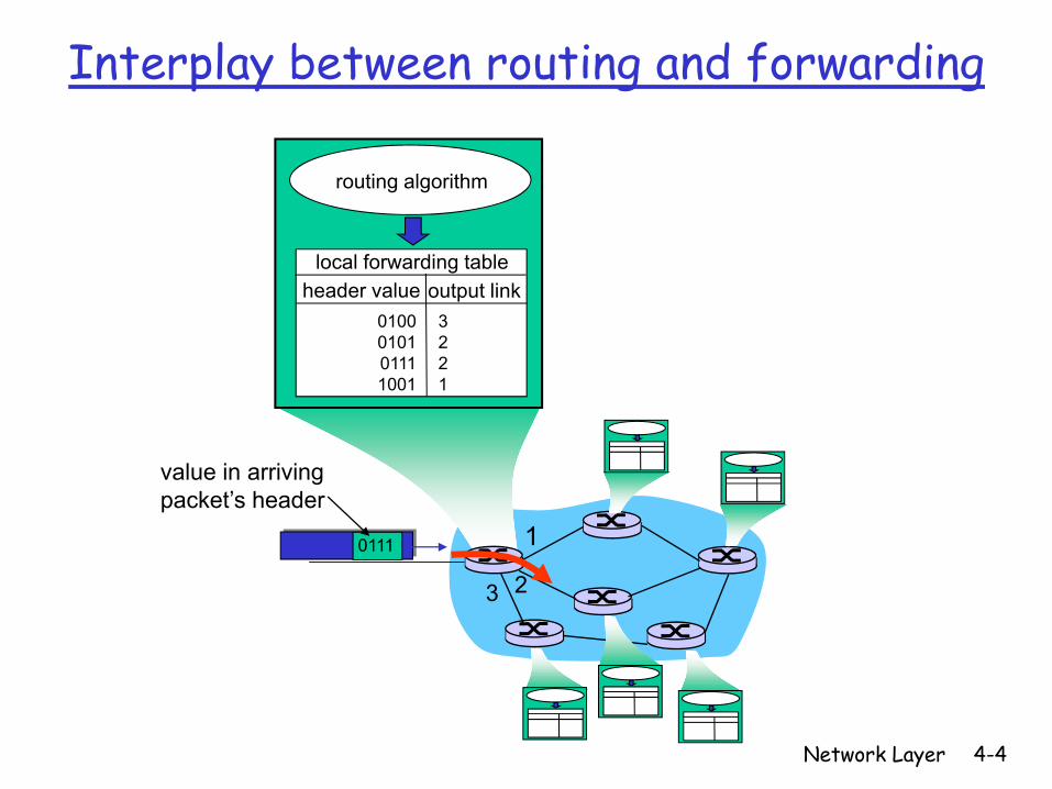
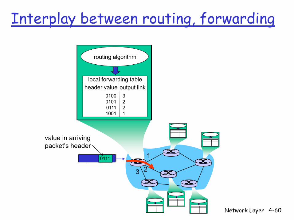
forwarding: move packets from router’s input to appropriate router output
routing: determine route taken by packets from source to dest.
routing algorithms
analogy:
routing: process of planning trip from source to dest
forwarding: process of getting through single interchange
Network Layer 4-4
1
23
0111
value in arrivingpacket’s header
routing algorithm
local forwarding tableheader value output link
0100010101111001
3221
Interplay between routing and forwarding
Network Layer 4-5
Connection setup
3rd important function in some network architectures:ATM, frame relay, X.25
before datagrams flow, two end hosts and intervening routers establish virtual connection
routers get involvednetwork vs transport layer connection service:
network: between two hosts (may also involve intervening routers in case of VCs)transport: between two processes
Network Layer 4-6
Network service modelQ: What service model for “channel” transporting datagrams from sender to receiver?
Example services for individual datagrams:guaranteed deliveryguaranteed delivery with less than 40 msec delay
Example services for a flow of datagrams:in-order datagram deliveryguaranteed minimum bandwidth to flowrestrictions on changes in inter-packet spacing
Network Layer 4-7
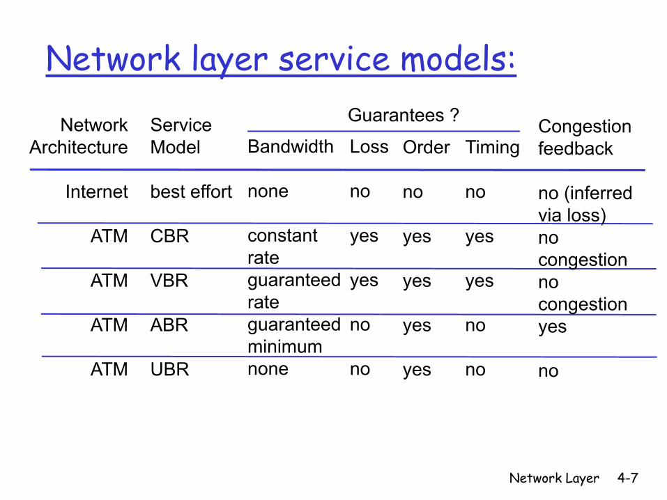
Network layer service models:
NetworkArchitecture
Internet
ATM
ATM
ATM
ATM
ServiceModel
best effort
CBR
VBR
ABR
UBR
Bandwidth
none
constantrateguaranteedrateguaranteed minimumnone
Loss
no
yes
yes
no
no
Order
no
yes
yes
yes
yes
Timing
no
yes
yes
no
no
Congestionfeedback
no (inferredvia loss)nocongestionnocongestionyes
no
Guarantees ?
Network Layer 4-8
Network layer connection and connection-less service
datagram network provides network-layer connectionless serviceVC network provides network-layer connection serviceanalogous to the transport-layer services, but:
service: host-to-hostno choice: network provides one or the otherimplementation: in network core
Network Layer 4-9
Virtual circuits
call setup, teardown for each call before data can floweach packet carries VC identifier (not destination host address)every router on source-dest path maintains “state” for each passing connectionlink, router resources (bandwidth, buffers) may be allocated to VC (dedicated resources = predictable service)
“source-to-dest path behaves much like telephone circuit”
performance-wisenetwork actions along source-to-dest path
Network Layer 4-10
VC implementation
a VC consists of:1. path from source to destination2. VC numbers, one number for each link along
path3. entries in forwarding tables in routers along
pathpacket belonging to VC carries VC number (rather than dest address)VC number can be changed on each link.
New VC number comes from forwarding table

Network Layer 4-11
Forwarding table12 22 32
1 23
VC number
interfacenumber
Incoming interface Incoming VC # Outgoing interface Outgoing VC #
1 12 3 222 63 1 18 3 7 2 171 97 3 87… … … …
Forwarding table innorthwest router:
Routers maintain connection state information!
Network Layer 4-12
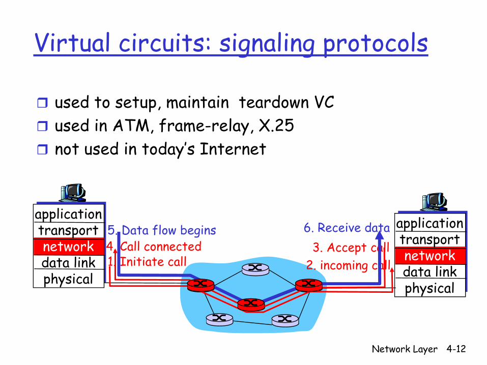
Virtual circuits: signaling protocols
used to setup, maintain teardown VCused in ATM, frame-relay, X.25not used in today’s Internet
applicationtransportnetworkdata linkphysical
applicationtransportnetworkdata linkphysical
1. Initiate call 2. incoming call3. Accept call4. Call connected
5. Data flow begins 6. Receive data
Network Layer 4-13
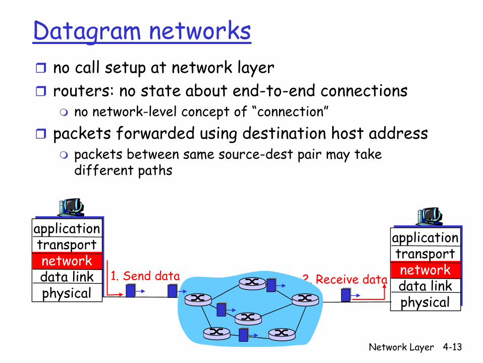
Datagram networksno call setup at network layerrouters: no state about end-to-end connections
no network-level concept of “connection”packets forwarded using destination host address
packets between same source-dest pair may take different paths
applicationtransportnetworkdata linkphysical
applicationtransportnetworkdata linkphysical
1. Send data 2. Receive data
Network Layer 4-14
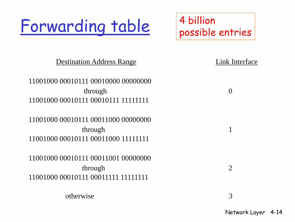
Forwarding table
Destination Address Range Link Interface
11001000 00010111 00010000 00000000through 0
11001000 00010111 00010111 11111111
11001000 00010111 00011000 00000000through 1
11001000 00010111 00011000 11111111
11001000 00010111 00011001 00000000through 2
11001000 00010111 00011111 11111111
otherwise 3
4 billion possible entries
Network Layer 4-15
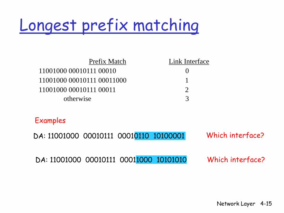
Longest prefix matching
Prefix Match Link Interface11001000 00010111 00010 011001000 00010111 00011000 111001000 00010111 00011 2
otherwise 3
DA: 11001000 00010111 00011000 10101010
Examples
DA: 11001000 00010111 00010110 10100001 Which interface?
Which interface?

Network Layer 4-16
Datagram or VC network: why?
Internet (datagram)data exchange among computers
“elastic” service, no strict timing req.
“smart” end systems (computers)
can adapt, perform control, error recoverysimple inside network, complexity at “edge”
many link types different characteristicsuniform service difficult
ATM (VC)evolved from telephonyhuman conversation:
strict timing, reliability requirementsneed for guaranteed service
“dumb” end systemstelephonescomplexity inside network

Network Layer 4-17
Router Architecture Overview
Two key router functions:run routing algorithms/protocol (RIP, OSPF, BGP)forwarding datagrams from incoming to outgoing link
Network Layer 4-18
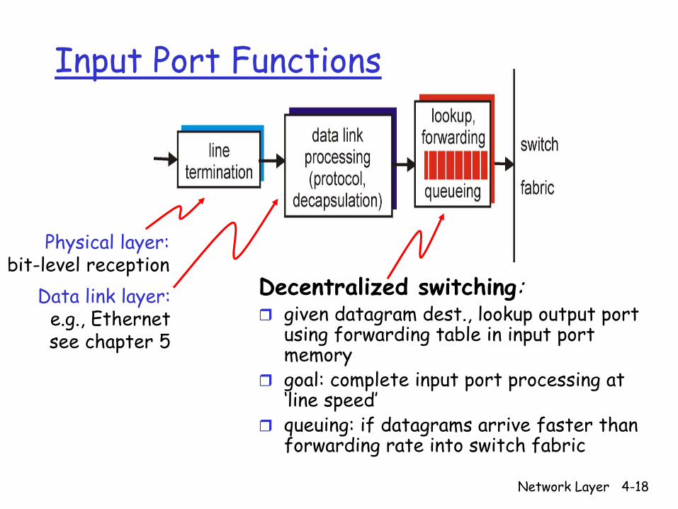
Input Port Functions
Decentralized switching:given datagram dest., lookup output port using forwarding table in input port memorygoal: complete input port processing at ‘line speed’queuing: if datagrams arrive faster than forwarding rate into switch fabric
Physical layer:bit-level reception
Data link layer:e.g., Ethernetsee chapter 5

Network Layer 4-19
Three types of switching fabrics

Network Layer 4-20
Switching Via MemoryFirst generation routers:
traditional computers with switching under direct control of CPUpacket copied to system’s memoryspeed limited by memory bandwidth (2 bus
crossings per datagram)InputPort
OutputPort
Memory
System Bus
Network Layer 4-21
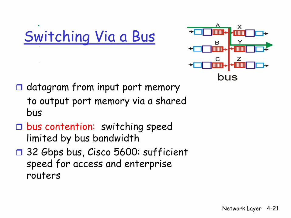
Switching Via a Bus
datagram from input port memoryto output port memory via a shared busbus contention: switching speed limited by bus bandwidth32 Gbps bus, Cisco 5600: sufficient speed for access and enterprise routers
Network Layer 4-22
Switching Via An Interconnection Network
overcome bus bandwidth limitationsBanyan networks, other interconnection nets initially developed to connect processors in multiprocessoradvanced design: fragmenting datagram into fixed length cells, switch cells through the fabric. Cisco 12000: switches 60 Gbps through the interconnection network

Network Layer 4-23
Output Ports
Buffering required when datagrams arrive from fabric faster than the transmission rateScheduling discipline chooses among queued datagrams for transmission
Network Layer 4-24
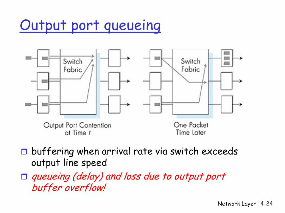
Output port queueing
buffering when arrival rate via switch exceeds output line speedqueueing (delay) and loss due to output port buffer overflow!
Network Layer 4-25
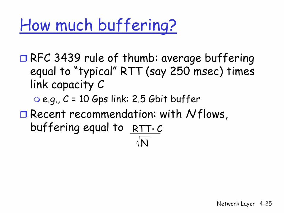
How much buffering?
RFC 3439 rule of thumb: average buffering equal to “typical” RTT (say 250 msec) times link capacity C
e.g., C = 10 Gps link: 2.5 Gbit bufferRecent recommendation: with N flows, buffering equal to RTT C.
N

Network Layer 4-26
Input Port Queuing
Fabric slower than input ports combined -> queueing may occur at input queues Head-of-the-Line (HOL) blocking: queued datagram at front of queue prevents others in queue from moving forwardqueueing delay and loss due to input buffer overflow!
Network Layer 4-27
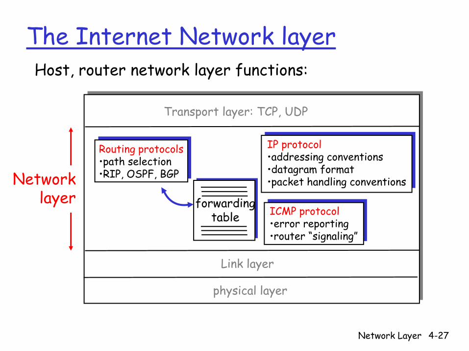
The Internet Network layer
forwardingtable
Host, router network layer functions:
Routing protocols•path selection•RIP, OSPF, BGP
IP protocol•addressing conventions•datagram format•packet handling conventions
ICMP protocol•error reporting•router “signaling”
Transport layer: TCP, UDP
Link layer
physical layer
Networklayer
Network Layer 4-28
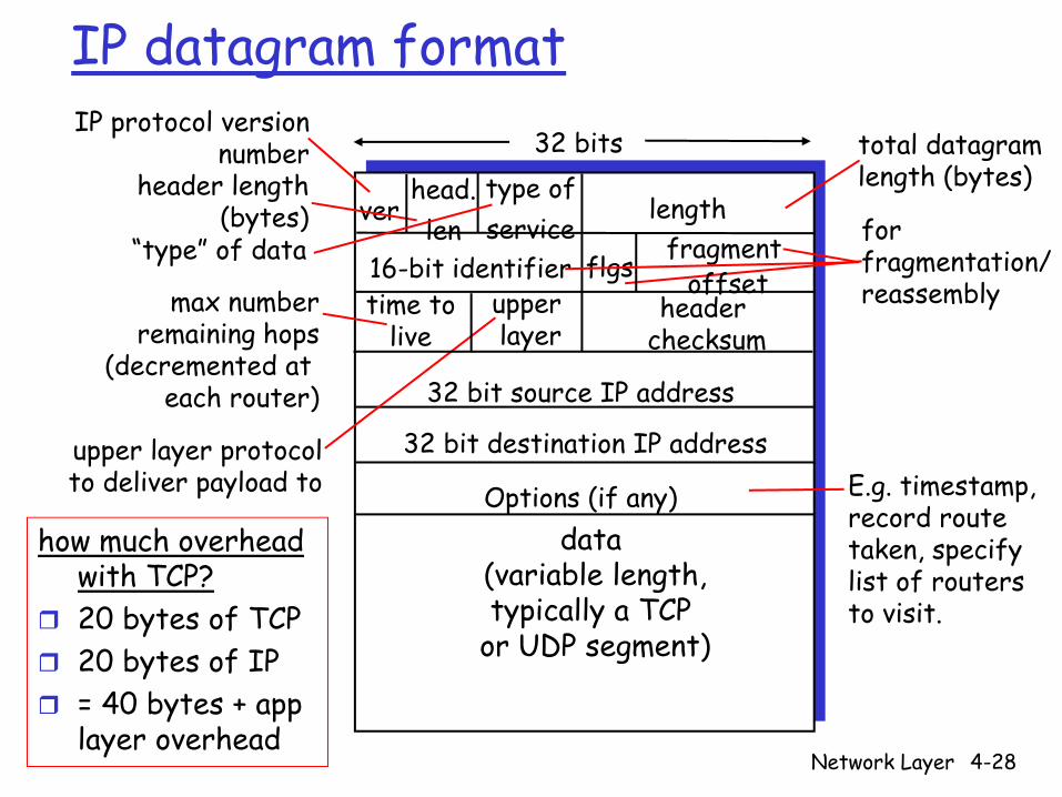
IP datagram format
ver length
32 bits
data (variable length,typically a TCP
or UDP segment)
16-bit identifierheader
checksumtime to
live
32 bit source IP address
IP protocol versionnumber
header length(bytes)
max numberremaining hops
(decremented at each router)
forfragmentation/reassembly
total datagramlength (bytes)
upper layer protocolto deliver payload to
head.len
type ofservice
“type” of data flgs fragmentoffset
upperlayer
32 bit destination IP address
Options (if any) E.g. timestamp,record routetaken, specifylist of routers to visit.
how much overhead with TCP?20 bytes of TCP20 bytes of IP= 40 bytes + app layer overhead
Network Layer 4-29
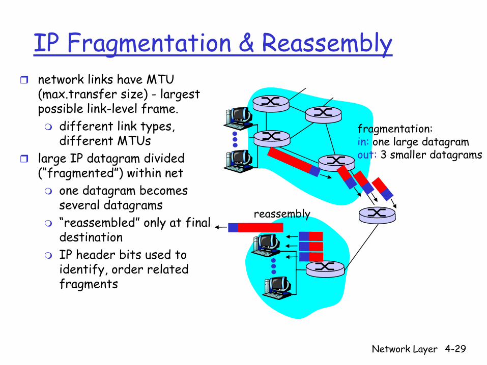
IP Fragmentation & Reassemblynetwork links have MTU (max.transfer size) - largest possible link-level frame.
different link types, different MTUs
large IP datagram divided (“fragmented”) within net
one datagram becomes several datagrams“reassembled” only at final destinationIP header bits used to identify, order related fragments
fragmentation: in: one large datagramout: 3 smaller datagrams
reassembly

Network Layer 4-30
IP Fragmentation and ReassemblyID=x
offset=0
fragflag=0
length=4000
ID=x
offset=0
fragflag=1
length=1500
ID=x
offset=185
fragflag=1
length=1500
ID=x
offset=370
fragflag=0
length=1040
One large datagram becomesseveral smaller datagrams
Example4000 byte datagramMTU = 1500 bytes
1480 bytes in data field
offset =1480/8
Network Layer 4-31
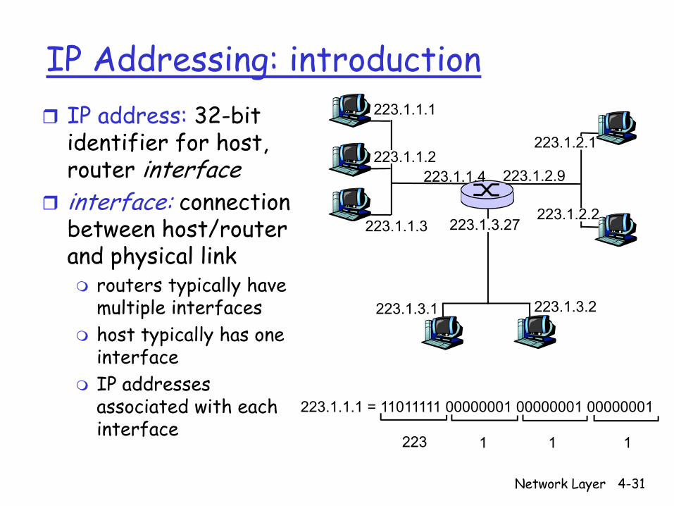
IP Addressing: introductionIP address: 32-bit identifier for host, router interfaceinterface: connection between host/router and physical link
routers typically have multiple interfaceshost typically has one interfaceIP addresses associated with each interface
223.1.1.1
223.1.1.2
223.1.1.3
223.1.1.4 223.1.2.9
223.1.2.2
223.1.2.1
223.1.3.2223.1.3.1
223.1.3.27
223.1.1.1 = 11011111 00000001 00000001 00000001
223 1 11
Network Layer 4-32
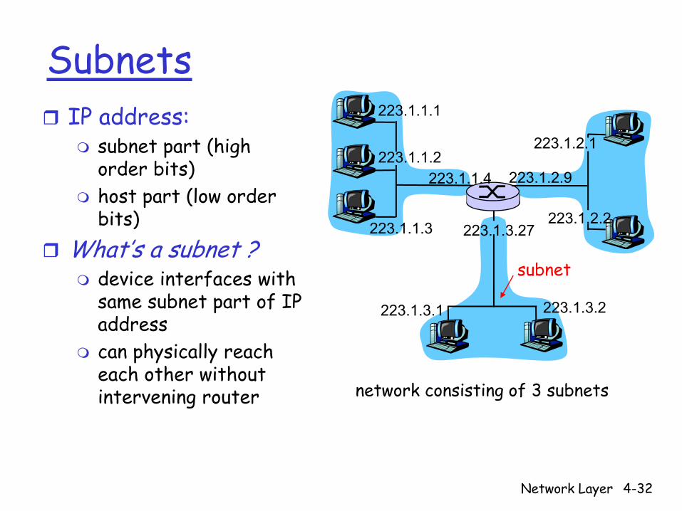
SubnetsIP address:
subnet part (high order bits)host part (low order bits)
What’s a subnet ?device interfaces with same subnet part of IP addresscan physically reach each other without intervening router
223.1.1.1
223.1.1.2
223.1.1.3
223.1.1.4 223.1.2.9
223.1.2.2
223.1.2.1
223.1.3.2223.1.3.1
223.1.3.27
network consisting of 3 subnets
subnet
Network Layer 4-33
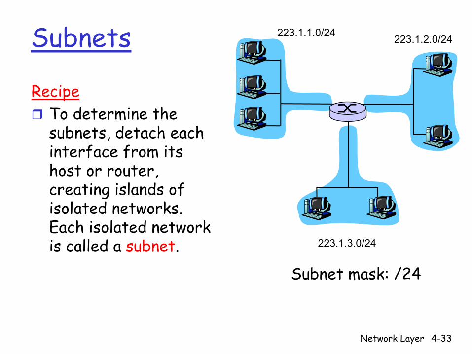
Subnets 223.1.1.0/24 223.1.2.0/24
223.1.3.0/24
RecipeTo determine the subnets, detach each interface from its host or router, creating islands of isolated networks. Each isolated network is called a subnet.
Subnet mask: /24
Network Layer 4-34
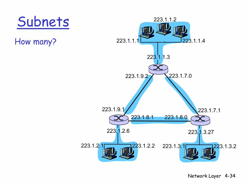
SubnetsHow many? 223.1.1.1
223.1.1.3
223.1.1.4
223.1.2.2223.1.2.1
223.1.2.6
223.1.3.2223.1.3.1
223.1.3.27
223.1.1.2
223.1.7.0
223.1.7.1223.1.8.0223.1.8.1
223.1.9.1
223.1.9.2
Network Layer 4-35
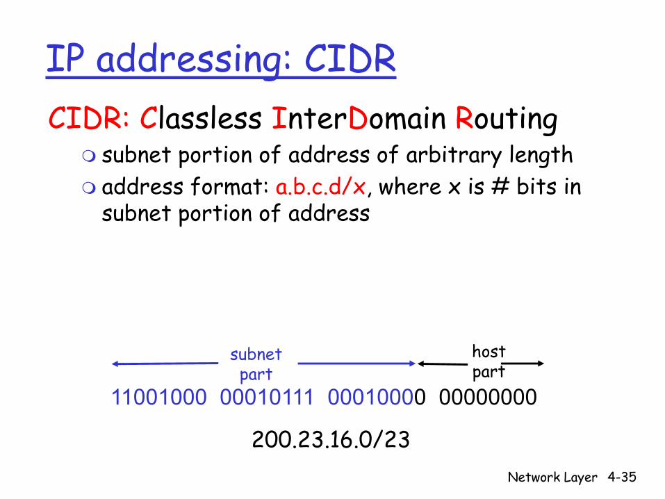
IP addressing: CIDRCIDR: Classless InterDomain Routing
subnet portion of address of arbitrary lengthaddress format: a.b.c.d/x, where x is # bits in subnet portion of address
11001000 00010111 00010000 00000000
subnetpart
hostpart
200.23.16.0/23
Network Layer 4-36
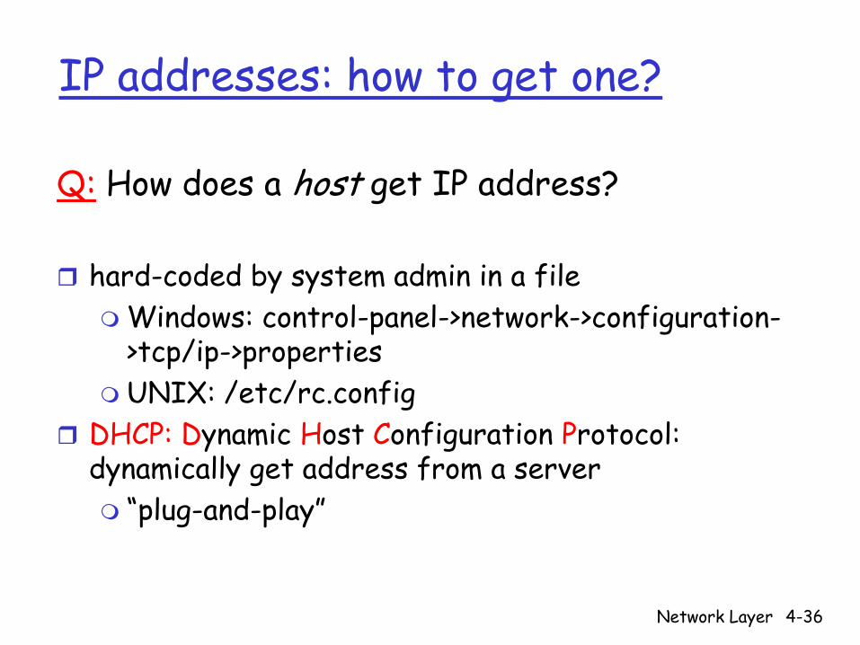
IP addresses: how to get one?
Q: How does a host get IP address?
hard-coded by system admin in a fileWindows: control-panel->network->configuration->tcp/ip->propertiesUNIX: /etc/rc.config
DHCP: Dynamic Host Configuration Protocol: dynamically get address from a server
“plug-and-play”
Network Layer 4-37
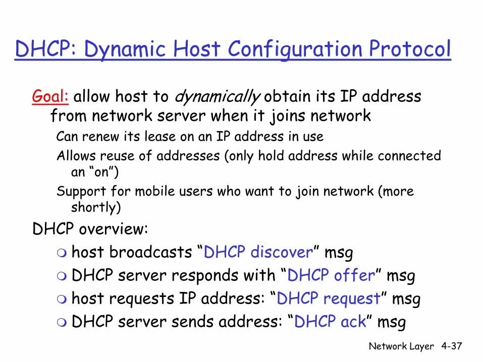
DHCP: Dynamic Host Configuration Protocol
Goal: allow host to dynamically obtain its IP address from network server when it joins networkCan renew its lease on an IP address in useAllows reuse of addresses (only hold address while connected
an “on”)Support for mobile users who want to join network (more
shortly)DHCP overview:
host broadcasts “DHCP discover” msgDHCP server responds with “DHCP offer” msghost requests IP address: “DHCP request” msgDHCP server sends address: “DHCP ack” msg

Network Layer 4-38
DHCP client-server scenario
223.1.1.1
223.1.1.2
223.1.1.3
223.1.1.4 223.1.2.9
223.1.2.2
223.1.2.1
223.1.3.2223.1.3.1
223.1.3.27
A
BE
DHCP server
arriving DHCP client needsaddress in thisnetwork
Network Layer 4-39
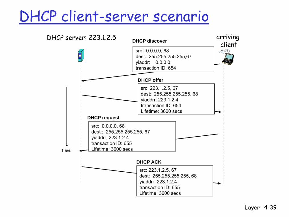
DHCP client-server scenarioDHCP server: 223.1.2.5 arriving
client
time
DHCP discover
src : 0.0.0.0, 68 dest.: 255.255.255.255,67yiaddr: 0.0.0.0transaction ID: 654
DHCP offersrc: 223.1.2.5, 67 dest: 255.255.255.255, 68yiaddrr: 223.1.2.4transaction ID: 654Lifetime: 3600 secs
DHCP request
src: 0.0.0.0, 68 dest:: 255.255.255.255, 67yiaddrr: 223.1.2.4transaction ID: 655Lifetime: 3600 secs
DHCP ACKsrc: 223.1.2.5, 67 dest: 255.255.255.255, 68yiaddrr: 223.1.2.4transaction ID: 655Lifetime: 3600 secs

Network Layer 4-40
IP addresses: how to get one?Q: How does network get subnet part of IP
addr?A: gets allocated portion of its provider ISP’s
address space
ISP's block 11001000 00010111 00010000 00000000 200.23.16.0/20
Organization 0 11001000 00010111 00010000 00000000 200.23.16.0/23 Organization 1 11001000 00010111 00010010 00000000 200.23.18.0/23 Organization 2 11001000 00010111 00010100 00000000 200.23.20.0/23
... ….. …. ….Organization 7 11001000 00010111 00011110 00000000 200.23.30.0/23
Network Layer 4-41
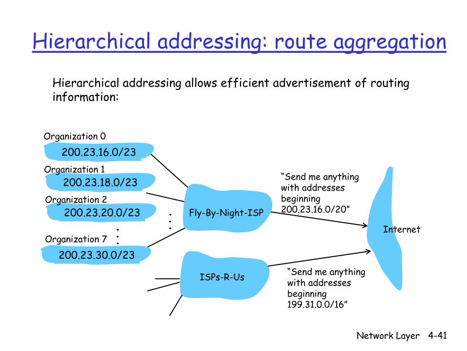
Hierarchical addressing: route aggregation
“Send me anythingwith addresses beginning 200.23.16.0/20”
200.23.16.0/23
200.23.18.0/23
200.23.30.0/23
Fly-By-Night-ISP
Organization 0
Organization 7Internet
Organization 1
ISPs-R-Us “Send me anythingwith addresses beginning 199.31.0.0/16”
200.23.20.0/23Organization 2
...
...
Hierarchical addressing allows efficient advertisement of routing information:
Network Layer 4-42
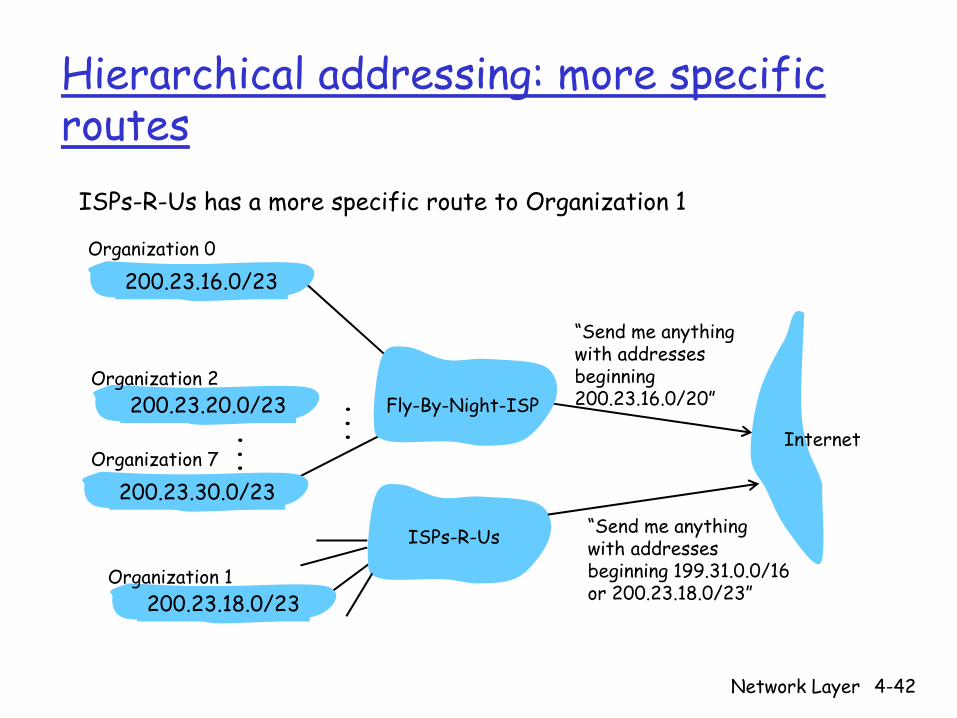
Hierarchical addressing: more specific routes
ISPs-R-Us has a more specific route to Organization 1
“Send me anythingwith addresses beginning 200.23.16.0/20”
200.23.16.0/23
200.23.18.0/23
200.23.30.0/23
Fly-By-Night-ISP
Organization 0
Organization 7Internet
Organization 1
ISPs-R-Us “Send me anythingwith addresses beginning 199.31.0.0/16or 200.23.18.0/23”
200.23.20.0/23Organization 2
...
...

Network Layer 4-43
IP addressing: the last word...
Q: How does an ISP get block of addresses?A: ICANN: Internet Corporation for Assigned
Names and Numbersallocates addressesmanages DNSassigns domain names, resolves disputes
Network Layer 4-44
NAT: Network Address Translation
10.0.0.1
10.0.0.2
10.0.0.3
10.0.0.4
138.76.29.7
local network(e.g., home network)
10.0.0/24
rest ofInternet
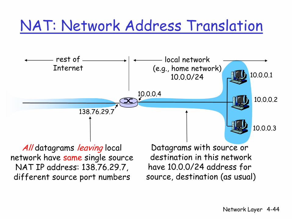
Datagrams with source or destination in this networkhave 10.0.0/24 address for source, destination (as usual)
All datagrams leaving localnetwork have same single source
NAT IP address: 138.76.29.7,different source port numbers

Network Layer 4-45
NAT: Network Address Translation
Motivation: local network uses just one IP address as far as outside world is concerned:
range of addresses not needed from ISP: just one IP address for all devicescan change addresses of devices in local network without notifying outside worldcan change ISP without changing addresses of devices in local networkdevices inside local net not explicitly addressable, visible by outside world (a security plus).

Network Layer 4-46
NAT: Network Address TranslationImplementation: NAT router must:
outgoing datagrams: replace (source IP address, port #) of every outgoing datagram to (NAT IP address, new port #). . . remote clients/servers will respond using (NAT
IP address, new port #) as destination addr.
remember (in NAT translation table) every (source IP address, port #) to (NAT IP address, new port #) translation pair
incoming datagrams: replace (NAT IP address, new port #) in dest fields of every incoming datagram with corresponding (source IP address, port #) stored in NAT table
Network Layer 4-47
NAT: Network Address Translation
10.0.0.1
10.0.0.2
10.0.0.3
S: 10.0.0.1, 3345D: 128.119.40.186, 80
110.0.0.4
138.76.29.7
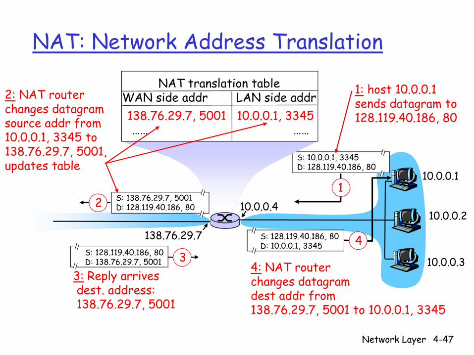
1: host 10.0.0.1 sends datagram to 128.119.40.186, 80
NAT translation tableWAN side addr LAN side addr138.76.29.7, 5001 10.0.0.1, 3345…… ……
S: 128.119.40.186, 80 D: 10.0.0.1, 3345 4
S: 138.76.29.7, 5001D: 128.119.40.186, 802
2: NAT routerchanges datagramsource addr from10.0.0.1, 3345 to138.76.29.7, 5001,updates table
S: 128.119.40.186, 80 D: 138.76.29.7, 5001 3
3: Reply arrivesdest. address:138.76.29.7, 5001
4: NAT routerchanges datagramdest addr from138.76.29.7, 5001 to 10.0.0.1, 3345
Network Layer 4-48
NAT: Network Address Translation
16-bit port-number field: 60,000 simultaneous connections with a single LAN-side address!
NAT is controversial:routers should only process up to layer 3violates end-to-end argument
• NAT possibility must be taken into account by app designers, eg, P2P applications
address shortage should instead be solved by IPv6
Network Layer 4-49
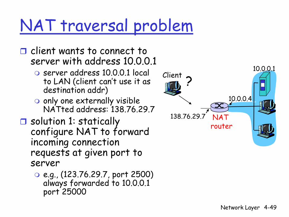
NAT traversal problemclient wants to connect to server with address 10.0.0.1
server address 10.0.0.1 local to LAN (client can’t use it as destination addr)only one externally visible NATted address: 138.76.29.7
solution 1: statically configure NAT to forward incoming connection requests at given port to server
e.g., (123.76.29.7, port 2500) always forwarded to 10.0.0.1 port 25000
10.0.0.1
10.0.0.4
NAT router
138.76.29.7
Client ?
Network Layer 4-50
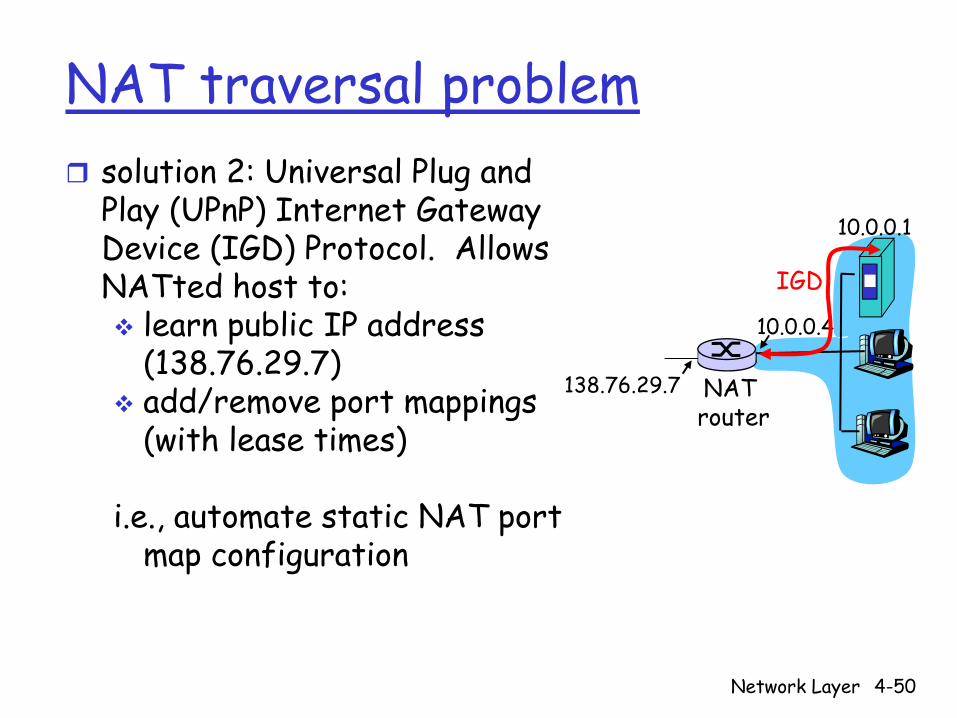
NAT traversal problemsolution 2: Universal Plug and Play (UPnP) Internet Gateway Device (IGD) Protocol. Allows NATted host to:
learn public IP address (138.76.29.7)add/remove port mappings (with lease times)
i.e., automate static NAT port map configuration
10.0.0.1
10.0.0.4
NAT router
138.76.29.7
IGD

Network Layer 4-51
NAT traversal problemsolution 3: relaying (used in Skype)
NATed client establishes connection to relayExternal client connects to relayrelay bridges packets between to connections
138.76.29.7Client
10.0.0.1
NAT router
1. connection torelay initiatedby NATted host
2. connection torelay initiatedby client
3. relaying established

Network Layer 4-52
ICMP: Internet Control Message Protocol
used by hosts & routers to communicate network-level information
error reporting: unreachable host, network, port, protocolecho request/reply (used by ping)
network-layer “above” IP:ICMP msgs carried in IP datagrams
ICMP message: type, code plus first 8 bytes of IP datagram causing error
Type Code description0 0 echo reply (ping)3 0 dest. network unreachable3 1 dest host unreachable3 2 dest protocol unreachable3 3 dest port unreachable3 6 dest network unknown3 7 dest host unknown4 0 source quench (congestion
control - not used)8 0 echo request (ping)9 0 route advertisement10 0 router discovery11 0 TTL expired12 0 bad IP header
Network Layer 4-53
Traceroute and ICMP
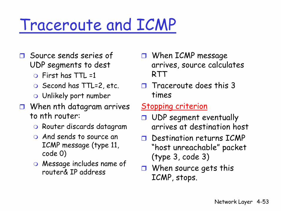
Source sends series of UDP segments to dest
First has TTL =1Second has TTL=2, etc.Unlikely port number
When nth datagram arrives to nth router:
Router discards datagramAnd sends to source an ICMP message (type 11, code 0)Message includes name of router& IP address
When ICMP message arrives, source calculates RTTTraceroute does this 3 times
Stopping criterionUDP segment eventually arrives at destination hostDestination returns ICMP “host unreachable” packet (type 3, code 3)When source gets this ICMP, stops.
Network Layer 4-54
IPv6Initial motivation: 32-bit address space soon to be completely allocated. Additional motivation:
header format helps speed processing/forwardingheader changes to facilitate QoS
IPv6 datagram format:fixed-length 40 byte headerno fragmentation allowed
Network Layer 4-55
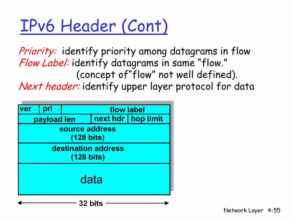
IPv6 Header (Cont)Priority: identify priority among datagrams in flowFlow Label: identify datagrams in same “flow.”
(concept of“flow” not well defined).Next header: identify upper layer protocol for data
Network Layer 4-56
Other Changes from IPv4
Checksum: removed entirely to reduce processing time at each hopOptions: allowed, but outside of header, indicated by “Next Header” fieldICMPv6: new version of ICMP
additional message types, e.g. “Packet Too Big”multicast group management functions
Network Layer 4-57
Transition From IPv4 To IPv6
Not all routers can be upgraded simultaneousno “flag days”How will the network operate with mixed IPv4 and IPv6 routers?
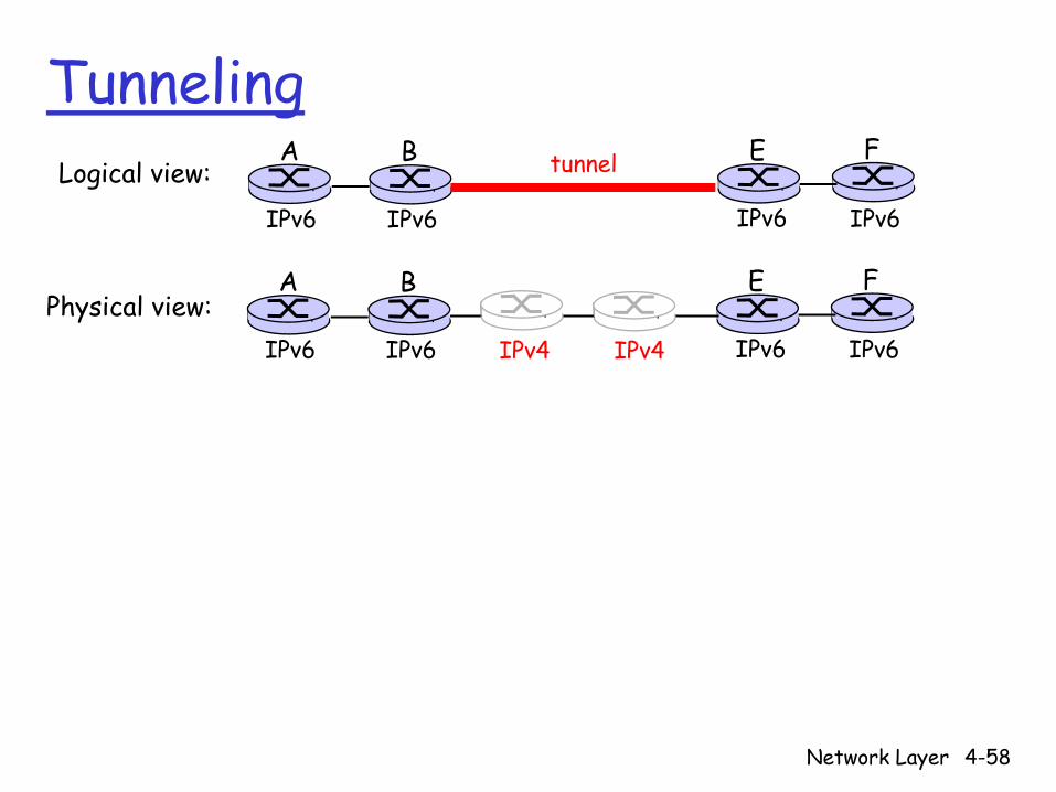
Tunneling: IPv6 carried as payload in IPv4 datagram among IPv4 routers
Network Layer 4-58
TunnelingA B E F
IPv6 IPv6 IPv6 IPv6
tunnelLogical view:
Physical view:A B E F
IPv6 IPv6 IPv6 IPv6IPv4 IPv4
Network Layer 4-59
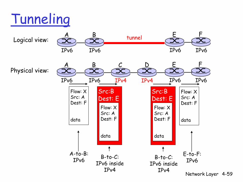
TunnelingA B E F
IPv6 IPv6 IPv6 IPv6
tunnelLogical view:
Physical view:A B E F
IPv6 IPv6 IPv6 IPv6
C D
IPv4 IPv4
Flow: XSrc: ADest: F
data
Flow: XSrc: ADest: F
data
Flow: XSrc: ADest: F
data
Src:BDest: E
Flow: XSrc: ADest: F
data
Src:BDest: E
A-to-B:IPv6
E-to-F:IPv6B-to-C:
IPv6 insideIPv4
B-to-C:IPv6 inside
IPv4
Network Layer 4-60
1
23
0111
value in arrivingpacket’s header
routing algorithm
local forwarding tableheader value output link
0100010101111001
3221
Interplay between routing, forwarding
Network Layer 4-61
u
yx
wv
z2
21
3
1
1
2
53
5
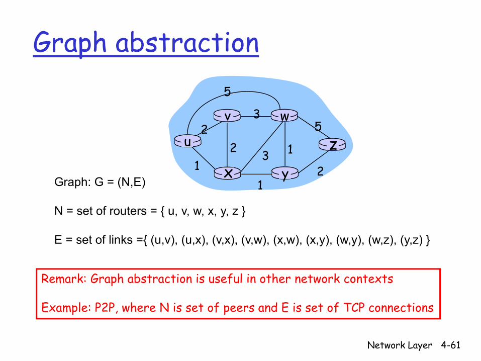
Graph: G = (N,E)
N = set of routers = { u, v, w, x, y, z }
E = set of links ={ (u,v), (u,x), (v,x), (v,w), (x,w), (x,y), (w,y), (w,z), (y,z) }
Graph abstraction
Remark: Graph abstraction is useful in other network contexts
Example: P2P, where N is set of peers and E is set of TCP connections
Network Layer 4-62
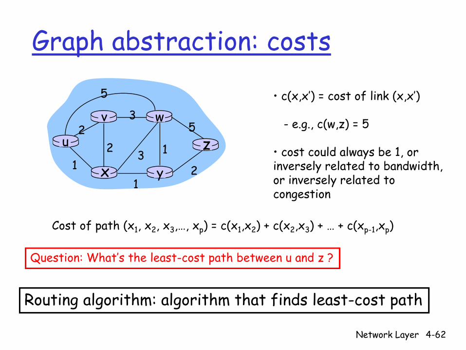
Graph abstraction: costs
u
yx
wv
z2
21
3
1
1
2
53
5 • c(x,x’) = cost of link (x,x’)
- e.g., c(w,z) = 5
• cost could always be 1, or inversely related to bandwidth,or inversely related to congestion
Cost of path (x1, x2, x3,…, xp) = c(x1,x2) + c(x2,x3) + … + c(xp-1,xp)
Question: What’s the least-cost path between u and z ?
Routing algorithm: algorithm that finds least-cost path
Network Layer 4-63
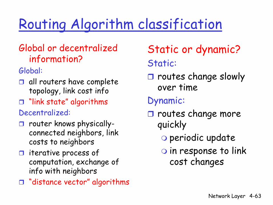
Routing Algorithm classificationGlobal or decentralized
information?Global:
all routers have complete topology, link cost info“link state” algorithms
Decentralized:router knows physically-connected neighbors, link costs to neighborsiterative process of computation, exchange of info with neighbors“distance vector” algorithms
Static or dynamic?Static:
routes change slowly over time
Dynamic:routes change more quickly
periodic updatein response to link cost changes
Network Layer 4-64
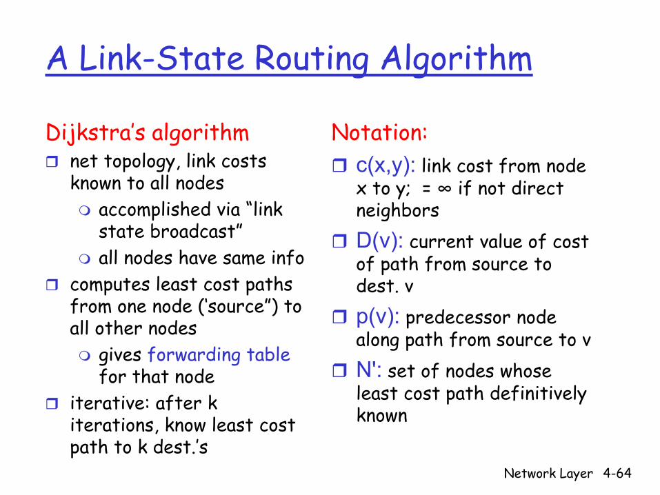
A Link-State Routing Algorithm
Dijkstra’s algorithmnet topology, link costs known to all nodes
accomplished via “link state broadcast” all nodes have same info
computes least cost paths from one node (‘source”) to all other nodes
gives forwarding tablefor that node
iterative: after k iterations, know least cost path to k dest.’s
Notation:c(x,y): link cost from node x to y; = ∞ if not direct neighborsD(v): current value of cost of path from source to dest. vp(v): predecessor node along path from source to vN': set of nodes whose least cost path definitively known

Network Layer 4-65
Dijsktra’s Algorithm1 Initialization:2 N' = {u} 3 for all nodes v 4 if v adjacent to u 5 then D(v) = c(u,v) 6 else D(v) = ∞7 8 Loop9 find w not in N' such that D(w) is a minimum 10 add w to N'11 update D(v) for all v adjacent to w and not in N' : 12 D(v) = min( D(v), D(w) + c(w,v) ) 13 /* new cost to v is either old cost to v or known 14 shortest path cost to w plus cost from w to v */ 15 until all nodes in N'
Network Layer 4-66
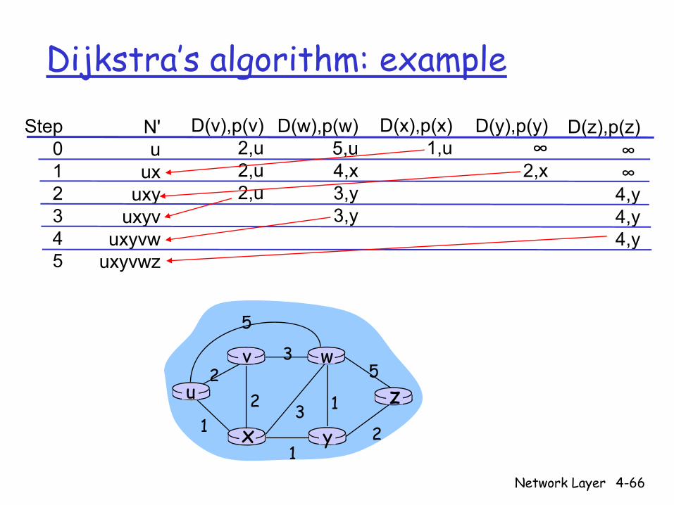
Dijkstra’s algorithm: example
Step012345
N'u
uxuxy
uxyvuxyvw
uxyvwz
D(v),p(v)2,u2,u2,u
D(w),p(w)5,u4,x3,y3,y
D(x),p(x)1,u
D(y),p(y)∞
2,x
D(z),p(z)∞ ∞
4,y4,y4,y
u
yx
wv
z2
21
3
1
1
2
53
5

Network Layer 4-67
Dijkstra’s algorithm: example (2)
u
yx
wv
z
Resulting shortest-path tree from u:
vxywz
(u,v)(u,x)(u,x)(u,x)(u,x)
destination link
Resulting forwarding table in u:
Network Layer 4-68
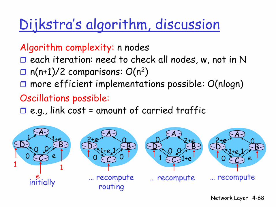
Dijkstra’s algorithm, discussionAlgorithm complexity: n nodes
each iteration: need to check all nodes, w, not in Nn(n+1)/2 comparisons: O(n2)more efficient implementations possible: O(nlogn)
Oscillations possible:e.g., link cost = amount of carried traffic
AD
CB
1 1+e
e0
e1 1
0 0
AD
CB
2+e 0
001+e 1
AD
CB
0 2+e
1+e10 0
AD
CB
2+e 0
e01+e 1
initially … recomputerouting
… recompute … recompute

Network Layer 4-69
Distance Vector Algorithm
Bellman-Ford Equation (dynamic programming)Definedx(y) := cost of least-cost path from x to y
Then
dx(y) = min {c(x,v) + dv(y) }
where min is taken over all neighbors v of x
v
Network Layer 4-70
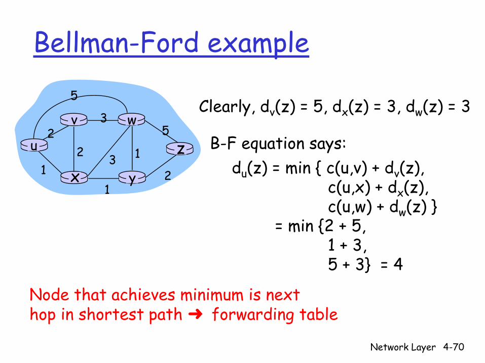
Bellman-Ford example
u
yx
wv
z2
21
3
1
1
2
53
5Clearly, dv(z) = 5, dx(z) = 3, dw(z) = 3
du(z) = min { c(u,v) + dv(z),c(u,x) + dx(z),c(u,w) + dw(z) }
= min {2 + 5,1 + 3,5 + 3} = 4
Node that achieves minimum is nexthop in shortest path ➜ forwarding table
B-F equation says:
Network Layer 4-71
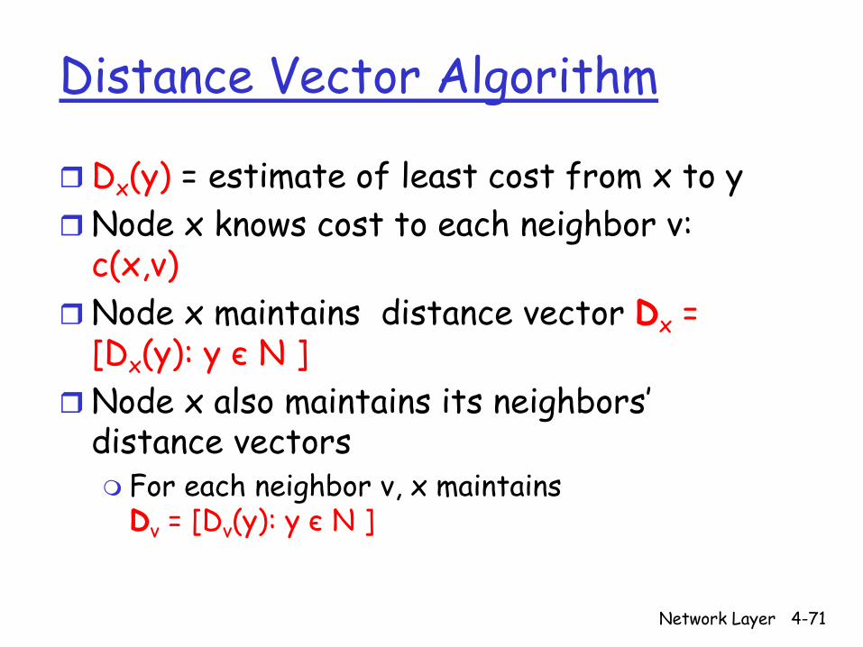
Distance Vector Algorithm
Dx(y) = estimate of least cost from x to yNode x knows cost to each neighbor v: c(x,v)Node x maintains distance vector Dx = [Dx(y): y є N ]Node x also maintains its neighbors’ distance vectors
For each neighbor v, x maintains Dv = [Dv(y): y є N ]
Network Layer 4-72
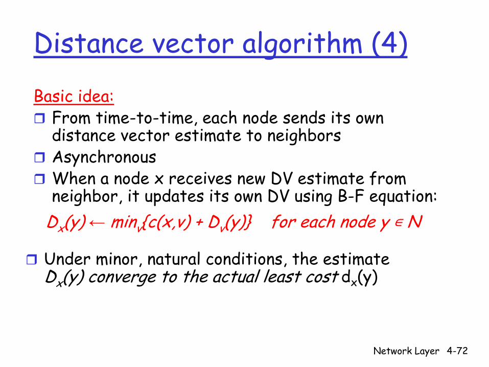
Distance vector algorithm (4)
Basic idea:From time-to-time, each node sends its own distance vector estimate to neighborsAsynchronousWhen a node x receives new DV estimate from neighbor, it updates its own DV using B-F equation:
Dx(y) ← minv{c(x,v) + Dv(y)} for each node y N
Under minor, natural conditions, the estimate Dx(y) converge to the actual least cost dx(y)
Network Layer 4-73
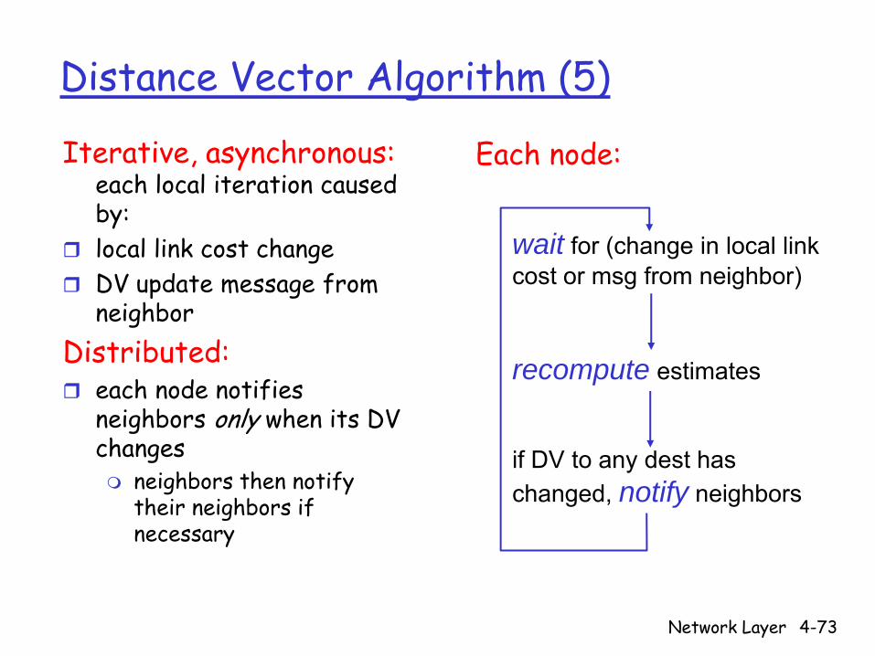
Distance Vector Algorithm (5)
Iterative, asynchronous: each local iteration caused by: local link cost change DV update message from neighbor
Distributed:each node notifies neighbors only when its DV changes
neighbors then notify their neighbors if necessary
wait for (change in local link cost or msg from neighbor)
recompute estimates
if DV to any dest has changed, notify neighbors
Each node:

Network Layer 4-74
x y zxyz
0 2 7∞∞ ∞∞∞ ∞
from
cost to
from
from
x y zxyz
0
from
cost to
x y zxyz
∞ ∞
∞∞ ∞
cost to
x y zxyz
∞∞ ∞7 1 0
cost to
∞2 0 1
∞ ∞ ∞
2 0 17 1 0
time
x z12
7
y
node x table
node y table
node z table
Dx(y) = min{c(x,y) + Dy(y), c(x,z) + Dz(y)}= min{2+0 , 7+1} = 2
Dx(z) = min{c(x,y) +Dy(z), c(x,z) + Dz(z)}
= min{2+1 , 7+0} = 3
32

Network Layer 4-75
x y zxyz
0 2 7∞∞ ∞∞∞ ∞
from
cost to
from
from
x y zxyz
0 2 3
from
cost tox y z
xyz
0 2 3
from
cost to
x y zxyz
∞ ∞
∞∞ ∞
cost tox y z
xyz
0 2 7
from
cost tox y z
xyz
0 2 3
from
cost to
x y zxyz
0 2 3
from
cost tox y z
xyz
0 2 7
from
cost tox y z
xyz
∞∞ ∞7 1 0
cost to
∞2 0 1
∞ ∞ ∞
2 0 17 1 0
2 0 17 1 0
2 0 13 1 0
2 0 13 1 0
2 0 1
3 1 02 0 1
3 1 0
time
x z12
7
y
node x table
node y table
node z table
Dx(y) = min{c(x,y) + Dy(y), c(x,z) + Dz(y)}= min{2+0 , 7+1} = 2
Dx(z) = min{c(x,y) +Dy(z), c(x,z) + Dz(z)}
= min{2+1 , 7+0} = 3
Network Layer 4-76
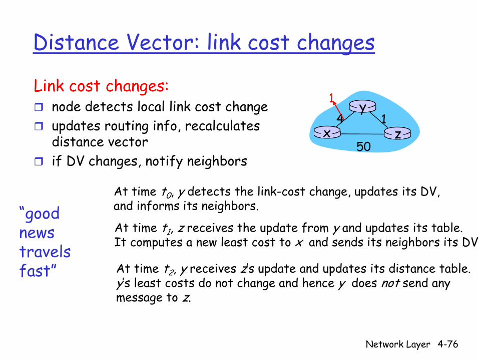
Distance Vector: link cost changes
Link cost changes:node detects local link cost change updates routing info, recalculates distance vectorif DV changes, notify neighbors
“goodnews travelsfast”
x z14
50
y1
At time t0, y detects the link-cost change, updates its DV, and informs its neighbors.
At time t1, z receives the update from y and updates its table. It computes a new least cost to x and sends its neighbors its DV.
At time t2, y receives z’s update and updates its distance table. y’s least costs do not change and hence y does not send any message to z.
Network Layer 4-77
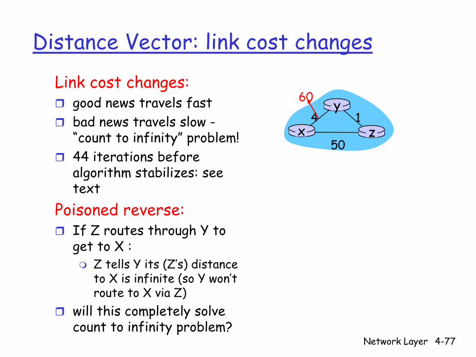
Distance Vector: link cost changes
Link cost changes:good news travels fast bad news travels slow -“count to infinity” problem!44 iterations before algorithm stabilizes: see text
Poisoned reverse:If Z routes through Y to get to X :
Z tells Y its (Z’s) distance to X is infinite (so Y won’t route to X via Z)
will this completely solve count to infinity problem?
x z14
50
y60
Network Layer 4-78
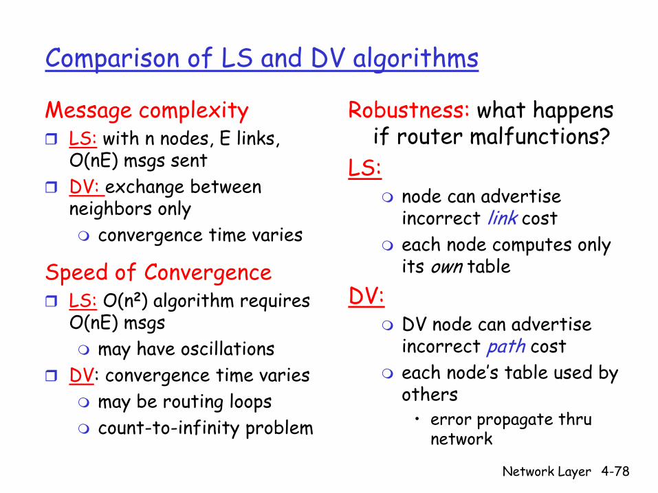
Comparison of LS and DV algorithms
Message complexityLS: with n nodes, E links, O(nE) msgs sent DV: exchange between neighbors only
convergence time varies
Speed of ConvergenceLS: O(n2) algorithm requires O(nE) msgs
may have oscillationsDV: convergence time varies
may be routing loopscount-to-infinity problem
Robustness: what happens if router malfunctions?
LS:node can advertise incorrect link costeach node computes only its own table
DV:DV node can advertise incorrect path costeach node’s table used by others
• error propagate thru network
Network Layer 4-79
Hierarchical Routing
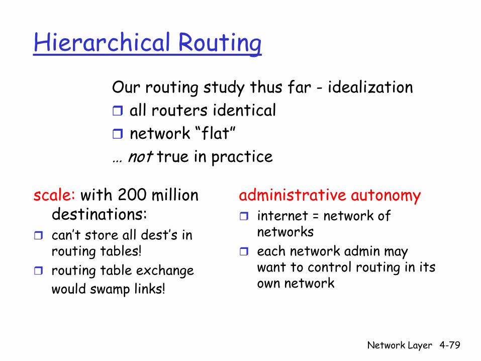
scale: with 200 million destinations:can’t store all dest’s in routing tables!routing table exchange would swamp links!
administrative autonomyinternet = network of networkseach network admin may want to control routing in its own network
Our routing study thus far - idealization all routers identicalnetwork “flat”
… not true in practice
Network Layer 4-80
Hierarchical Routing
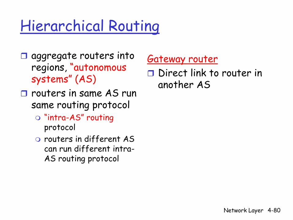
aggregate routers into regions, “autonomous systems” (AS)routers in same AS run same routing protocol
“intra-AS” routingprotocolrouters in different AS can run different intra-AS routing protocol
Gateway routerDirect link to router in another AS
Network Layer 4-81
3b
1d
3a
1c2aAS3
AS1AS2
1a
2c2b
1b
Intra-ASRouting algorithm
Inter-ASRouting algorithm
Forwardingtable
3c
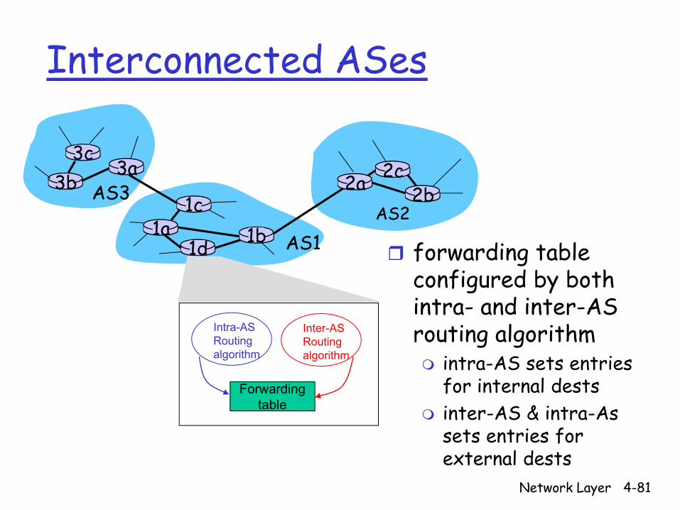
Interconnected ASes
forwarding table configured by both intra- and inter-AS routing algorithm
intra-AS sets entries for internal destsinter-AS & intra-As sets entries for external dests

Network Layer 4-82
3b
1d
3a
1c2aAS3
AS1AS2
1a
2c2b
1b
3c
Inter-AS taskssuppose router in AS1 receives datagram destined outside of AS1:
router should forward packet to gateway router, but which one?
AS1 must:1. learn which dests are
reachable through AS2, which through AS3
2. propagate this reachability info to all routers in AS1
Job of inter-AS routing!

Network Layer 4-83
Example: Setting forwarding table in router 1d
suppose AS1 learns (via inter-AS protocol) that subnet x reachable via AS3 (gateway 1c) but not via AS2.inter-AS protocol propagates reachability info to all internal routers.router 1d determines from intra-AS routing info that its interface I is on the least cost path to 1c.
installs forwarding table entry (x,I)
3b
1d
3a
1c2aAS3
AS1AS2
1a
2c2b
1b
3cx

Network Layer 4-84
Example: Choosing among multiple ASes
now suppose AS1 learns from inter-AS protocol that subnet x is reachable from AS3 and from AS2.to configure forwarding table, router 1d must determine towards which gateway it should forward packets for dest x.
this is also job of inter-AS routing protocol!
3b
1d
3a
1c2aAS3
AS1AS2
1a
2c2b
1b
3cx
Network Layer 4-85
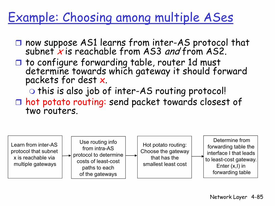
Learn from inter-AS protocol that subnet x is reachable via multiple gateways
Use routing infofrom intra-AS
protocol to determinecosts of least-cost
paths to eachof the gateways
Hot potato routing:Choose the gateway
that has the smallest least cost
Determine fromforwarding table the interface I that leads
to least-cost gateway. Enter (x,I) in
forwarding table
Example: Choosing among multiple ASes
now suppose AS1 learns from inter-AS protocol that subnet x is reachable from AS3 and from AS2.to configure forwarding table, router 1d must determine towards which gateway it should forward packets for dest x.
this is also job of inter-AS routing protocol!hot potato routing: send packet towards closest of two routers.

Network Layer 4-86
Intra-AS Routing
also known as Interior Gateway Protocols (IGP)most common Intra-AS routing protocols:
RIP: Routing Information Protocol
OSPF: Open Shortest Path First
IGRP: Interior Gateway Routing Protocol (Cisco proprietary)
Network Layer 4-87
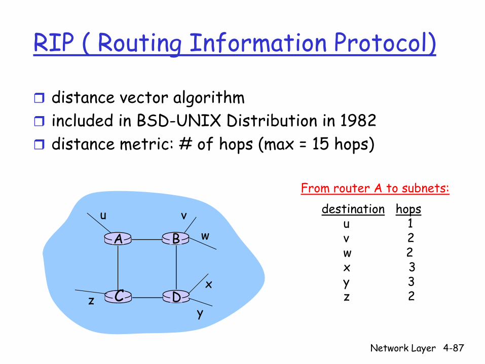
RIP ( Routing Information Protocol)
distance vector algorithmincluded in BSD-UNIX Distribution in 1982distance metric: # of hops (max = 15 hops)
DC
BA
u vw
x
yz
destination hopsu 1v 2w 2x 3y 3z 2
From router A to subnets:
Network Layer 4-88
RIP advertisements
distance vectors: exchanged among neighbors every 30 sec via Response Message (also called advertisement)each advertisement: list of up to 25 destination subnets within AS

Network Layer 4-89
RIP: Example
Destination Network Next Router Num. of hops to dest.w A 2y B 2z B 7x -- 1…. …. ....
w x y
z
A
C
D B
Routing/Forwarding table in D
Network Layer 4-90
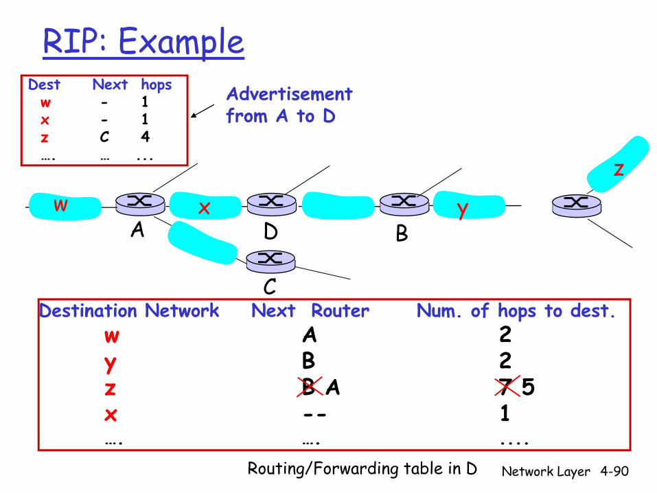
RIP: Example
Destination Network Next Router Num. of hops to dest.w A 2y B 2z B A 7 5x -- 1…. …. ....
Routing/Forwarding table in D
w x y
z
A
C
D B
Dest Next hopsw - 1x - 1z C 4…. … ...
Advertisementfrom A to D
Network Layer 4-91
RIP: Link Failure and RecoveryIf no advertisement heard after 180 sec -->
neighbor/link declared deadroutes via neighbor invalidatednew advertisements sent to neighborsneighbors in turn send out new advertisements (if tables changed)link failure info quickly (?) propagates to entire netpoison reverse used to prevent ping-pong loops (infinite distance = 16 hops)
Network Layer 4-92
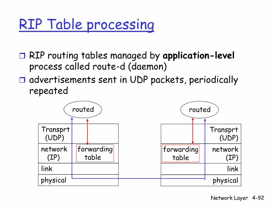
RIP Table processing
RIP routing tables managed by application-levelprocess called route-d (daemon)advertisements sent in UDP packets, periodically repeated
physicallink
network forwarding(IP) table
Transprt(UDP)
routed
physicallink
network(IP)
Transprt(UDP)
routed
forwardingtable
Network Layer 4-93
OSPF (Open Shortest Path First)
“open”: publicly availableuses Link State algorithm
LS packet disseminationtopology map at each noderoute computation using Dijkstra’s algorithm
OSPF advertisement carries one entry per neighbor routeradvertisements disseminated to entire AS (via flooding)
carried in OSPF messages directly over IP (rather than TCP or UDP
Network Layer 4-94
OSPF “advanced” features (not in RIP)
security: all OSPF messages authenticated (to prevent malicious intrusion) multiple same-cost paths allowed (only one path in RIP)For each link, multiple cost metrics for different TOS (e.g., satellite link cost set “low” for best effort; high for real time)integrated uni- and multicast support:
Multicast OSPF (MOSPF) uses same topology data base as OSPF
hierarchical OSPF in large domains.

Network Layer 4-95
Hierarchical OSPF
Network Layer 4-96
Hierarchical OSPF
two-level hierarchy: local area, backbone.Link-state advertisements only in area each nodes has detailed area topology; only know direction (shortest path) to nets in other areas.
area border routers: “summarize” distances to nets in own area, advertise to other Area Border routers.backbone routers: run OSPF routing limited to backbone.boundary routers: connect to other AS’s.
Network Layer 4-97
Internet inter-AS routing: BGP
BGP (Border Gateway Protocol): the de facto standardBGP provides each AS a means to:1. Obtain subnet reachability information from
neighboring ASs.2. Propagate reachability information to all AS-
internal routers.3. Determine “good” routes to subnets based on
reachability information and policy.allows subnet to advertise its existence to rest of Internet: “I am here”
Network Layer 4-98
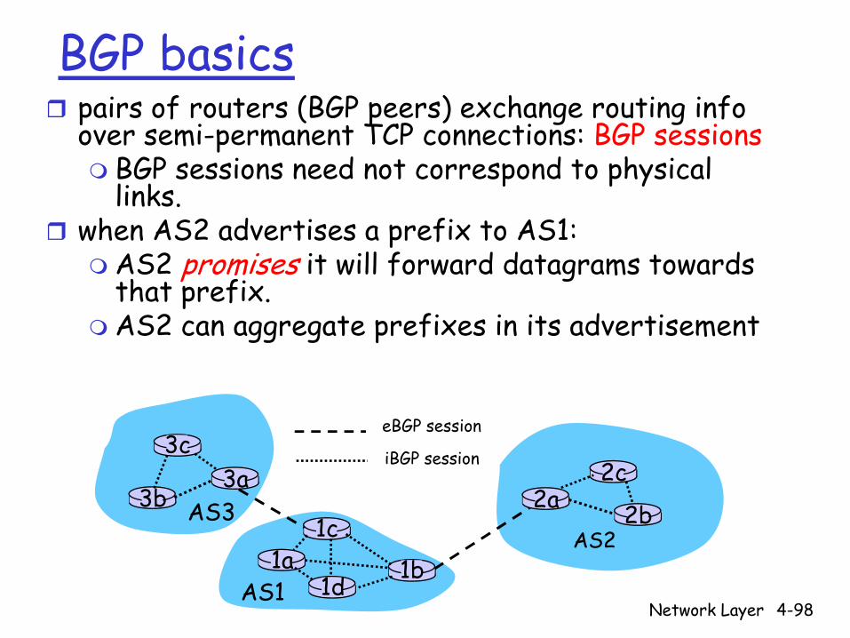
BGP basicspairs of routers (BGP peers) exchange routing info over semi-permanent TCP connections: BGP sessions
BGP sessions need not correspond to physical links.
when AS2 advertises a prefix to AS1:AS2 promises it will forward datagrams towards that prefix.AS2 can aggregate prefixes in its advertisement
3b
1d
3a
1c2aAS3
AS1
AS21a
2c
2b
1b
3ceBGP session
iBGP session
Network Layer 4-99
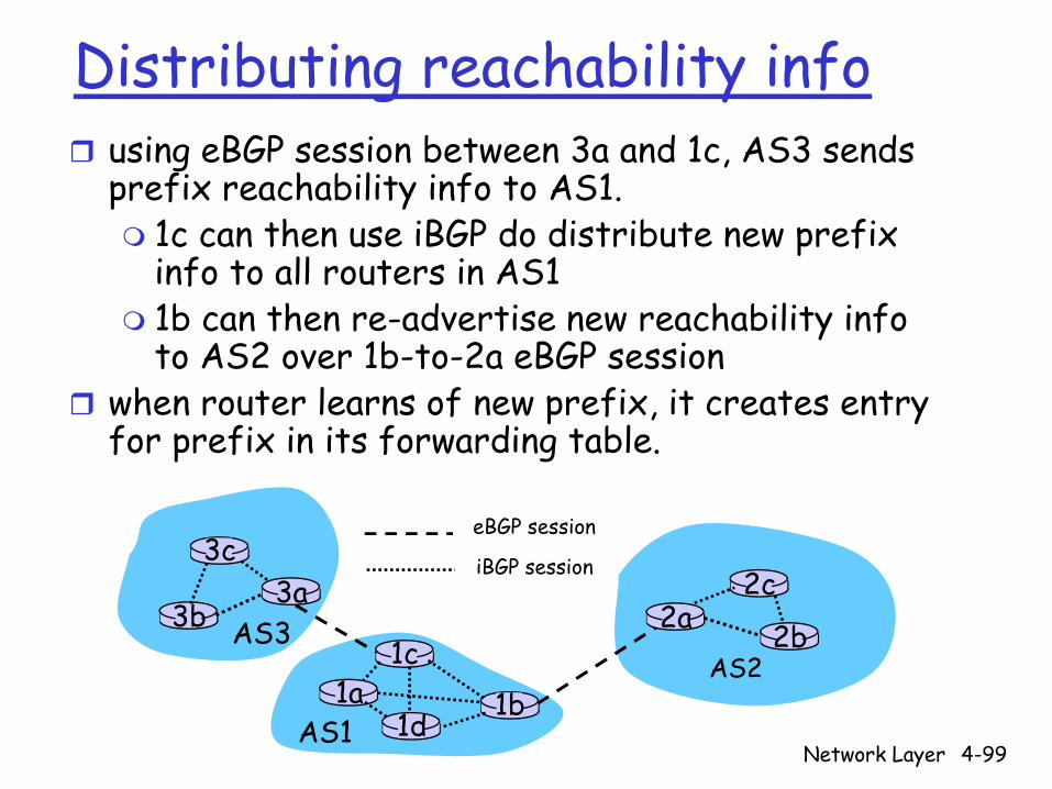
Distributing reachability infousing eBGP session between 3a and 1c, AS3 sends prefix reachability info to AS1.
1c can then use iBGP do distribute new prefix info to all routers in AS11b can then re-advertise new reachability info to AS2 over 1b-to-2a eBGP session
when router learns of new prefix, it creates entry for prefix in its forwarding table.
3b
1d
3a
1c2aAS3
AS1
AS21a
2c
2b
1b
3ceBGP session
iBGP session

Network Layer 4-100
Path attributes & BGP routes
advertised prefix includes BGP attributes. prefix + attributes = “route”
two important attributes:AS-PATH: contains ASs through which prefix advertisement has passed: e.g, AS 67, AS 17 NEXT-HOP: indicates specific internal-AS router to next-hop AS. (may be multiple links from current AS to next-hop-AS)
when gateway router receives route advertisement, uses import policy to accept/decline.
Network Layer 4-101
BGP route selection
router may learn about more than 1 route to some prefix. Router must select route.elimination rules:
1. local preference value attribute: policy decision
2. shortest AS-PATH 3. closest NEXT-HOP router: hot potato routing4. additional criteria

Network Layer 4-102
BGP messages
BGP messages exchanged using TCP.BGP messages:
OPEN: opens TCP connection to peer and authenticates senderUPDATE: advertises new path (or withdraws old)KEEPALIVE keeps connection alive in absence of UPDATES; also ACKs OPEN requestNOTIFICATION: reports errors in previous msg; also used to close connection
Network Layer 4-103
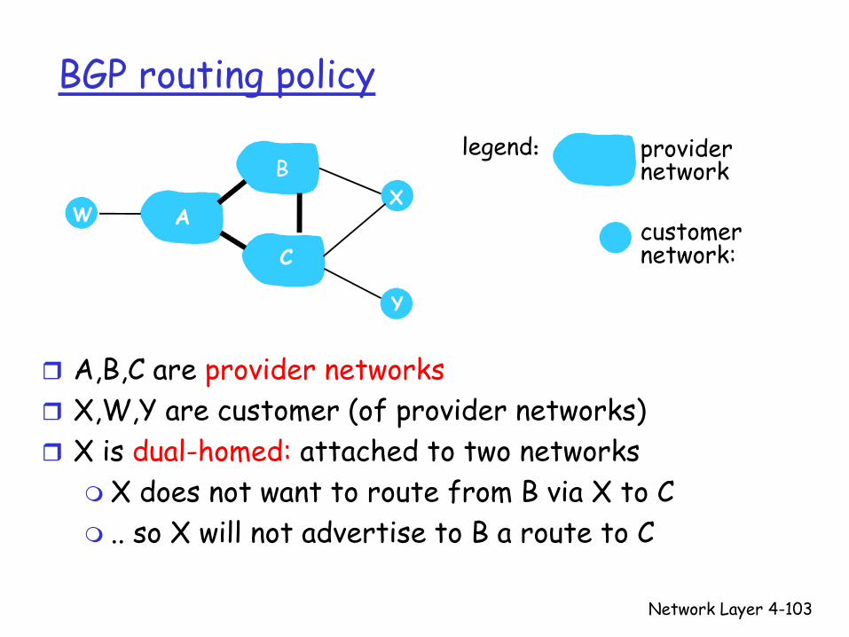
BGP routing policy
A,B,C are provider networksX,W,Y are customer (of provider networks)X is dual-homed: attached to two networks
X does not want to route from B via X to C.. so X will not advertise to B a route to C
A
B
C
WX
Y
legend:
customer network:
providernetwork
Network Layer 4-104
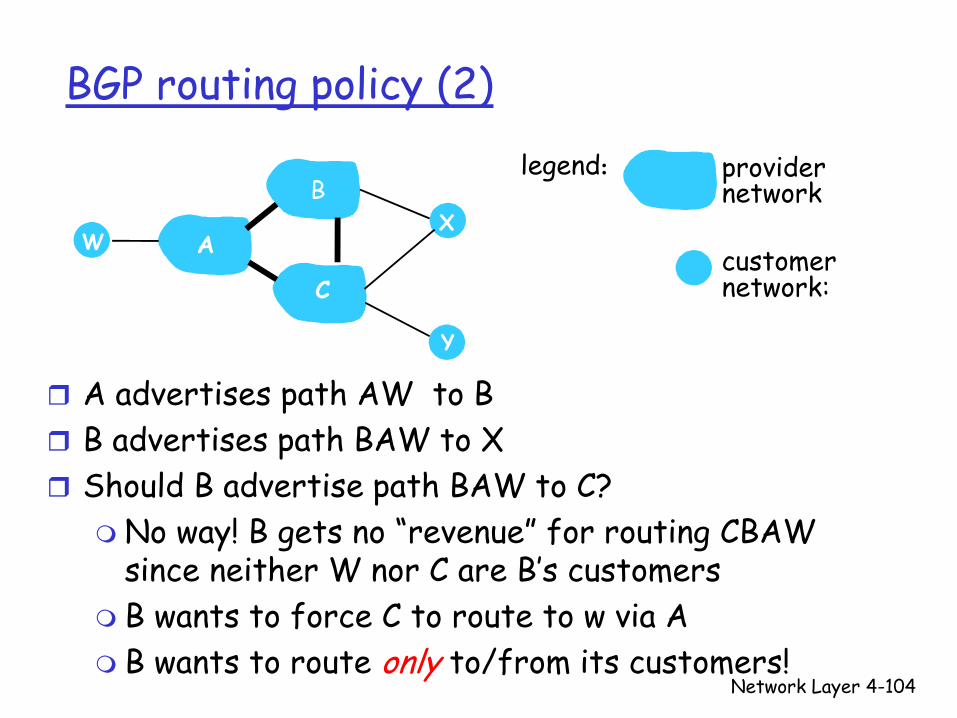
BGP routing policy (2)
A advertises path AW to BB advertises path BAW to X Should B advertise path BAW to C?
No way! B gets no “revenue” for routing CBAW since neither W nor C are B’s customers B wants to force C to route to w via AB wants to route only to/from its customers!
A
B
C
WX
Y
legend:
customer network:
providernetwork

Network Layer 4-105
Why different Intra- and Inter-AS routing ?
Policy:Inter-AS: admin wants control over how its traffic routed, who routes through its net. Intra-AS: single admin, so no policy decisions needed
Scale:hierarchical routing saves table size, reduced update traffic
Performance:Intra-AS: can focus on performanceInter-AS: policy may dominate over performance
Network Layer 4-106
R1
R2
R3 R4
sourceduplication
R1
R2
R3 R4
in-networkduplication
duplicatecreation/transmissionduplicate
duplicate
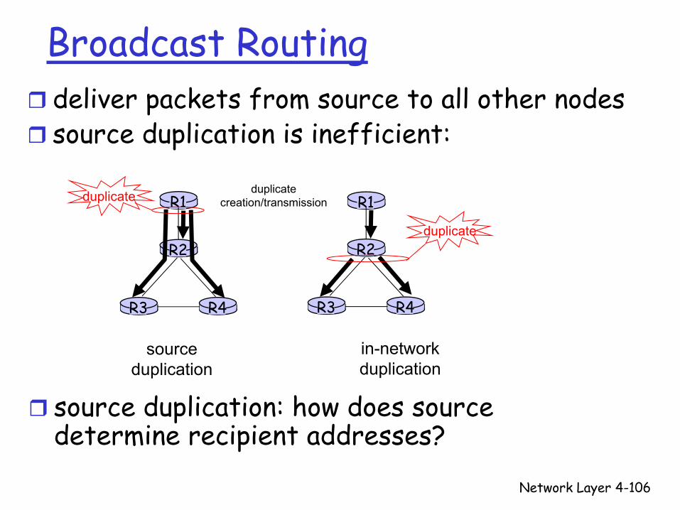
Broadcast Routingdeliver packets from source to all other nodessource duplication is inefficient:
source duplication: how does source determine recipient addresses?
Network Layer 4-107
In-network duplication
flooding: when node receives brdcst pckt, sends copy to all neighbors
Problems: cycles & broadcast stormcontrolled flooding: node only brdcsts pkt if it hasn’t brdcst same packet before
Node keeps track of pckt ids already brdcstedOr reverse path forwarding (RPF): only forward pckt if it arrived on shortest path between node and source
spanning treeNo redundant packets received by any node
Network Layer 4-108
A
B
G
DE
c
F
A
B
G
DE
c
F
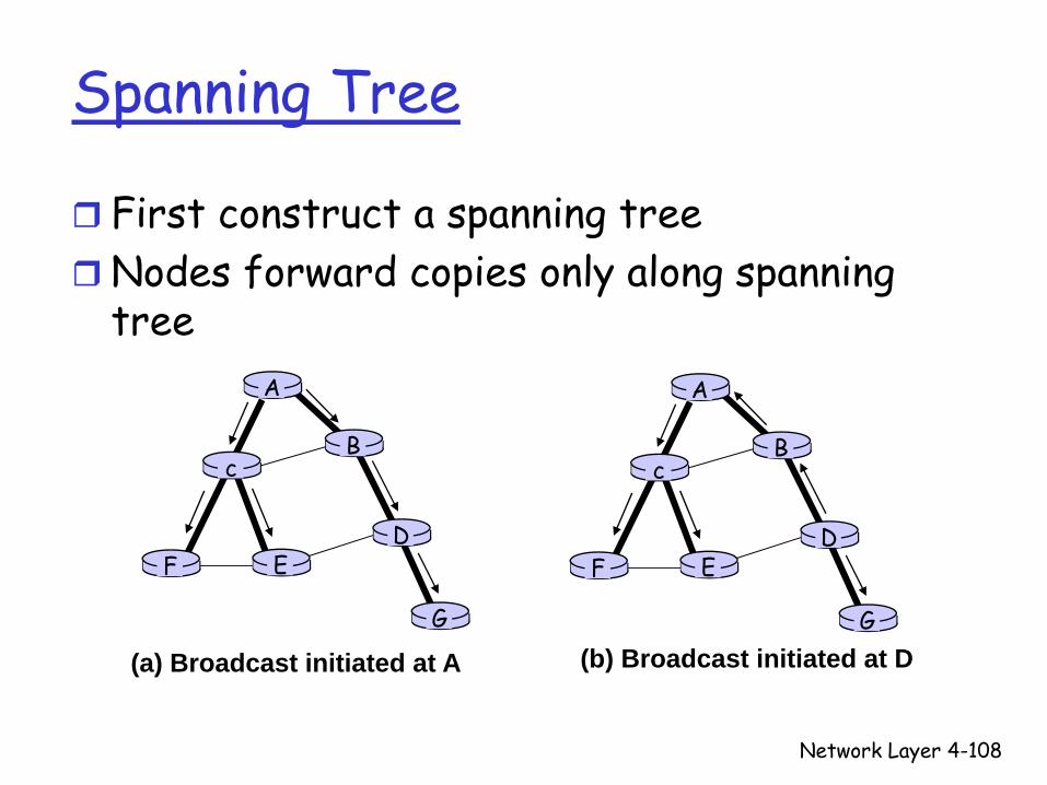
(a) Broadcast initiated at A (b) Broadcast initiated at D
Spanning Tree
First construct a spanning treeNodes forward copies only along spanning tree

Network Layer 4-109
A
B
G
DE
c
F1
2
3
4
5
(a) Stepwise construction of spanning tree
A
B
G
DE
c
F
(b) Constructed spanning tree
Spanning Tree: CreationCenter nodeEach node sends unicast join message to center node
Message forwarded until it arrives at a node already belonging to spanning tree

Multicast Routing: Problem StatementGoal: find a tree (or trees) connecting routers having local mcast group members
tree: not all paths between routers usedsource-based: different tree from each sender to rcvrsshared-tree: same tree used by all group members
Shared tree Source-based trees
Approaches for building mcast trees
Approaches:source-based tree: one tree per source
shortest path treesreverse path forwarding
group-shared tree: group uses one treeminimal spanning (Steiner) center-based trees
…we first look at basic approaches, then specific protocols adopting these approaches

Shortest Path Tree
mcast forwarding tree: tree of shortest path routes from source to all receivers
Dijkstra’s algorithm
R1
R2
R3
R4
R5
R6 R7
21
6
3 45
i
router with attachedgroup member
router with no attachedgroup memberlink used for forwarding,i indicates order linkadded by algorithm
LEGENDS: source
Reverse Path Forwarding
if (mcast datagram received on incoming link on shortest path back to center)then flood datagram onto all outgoing linkselse ignore datagram
rely on router’s knowledge of unicast shortest path from it to sendereach router has simple forwarding behavior:
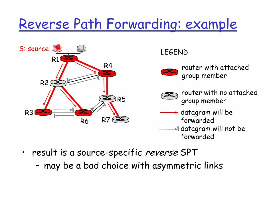
Reverse Path Forwarding: example
• result is a source-specific reverse SPT– may be a bad choice with asymmetric links
R1
R2
R3
R4
R5
R6 R7
router with attachedgroup member
router with no attachedgroup memberdatagram will be forwarded
LEGENDS: source
datagram will not be forwarded

Reverse Path Forwarding: pruningforwarding tree contains subtrees with no mcast group members
no need to forward datagrams down subtree“prune” msgs sent upstream by router with no downstream group members
R1
R2
R3
R4
R5
R6 R7
router with attachedgroup memberrouter with no attachedgroup memberprune message
LEGENDS: source
links with multicastforwarding
P
P
P
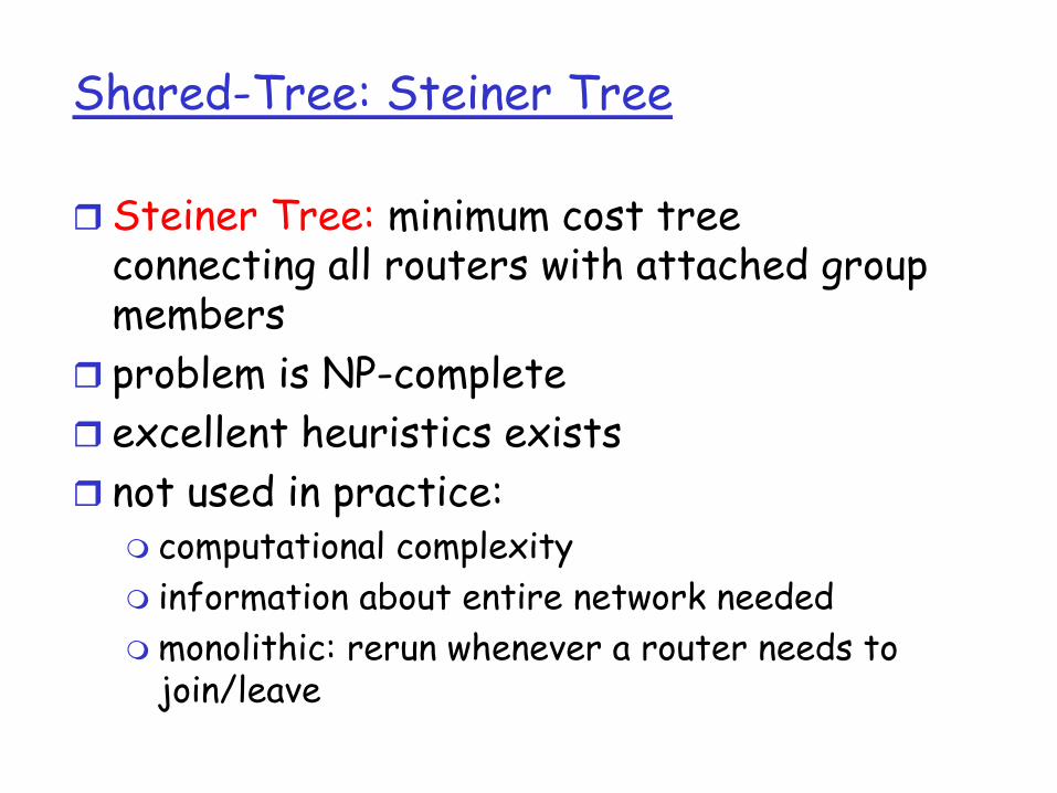
Shared-Tree: Steiner Tree
Steiner Tree: minimum cost tree connecting all routers with attached group membersproblem is NP-completeexcellent heuristics existsnot used in practice:
computational complexityinformation about entire network neededmonolithic: rerun whenever a router needs to join/leave
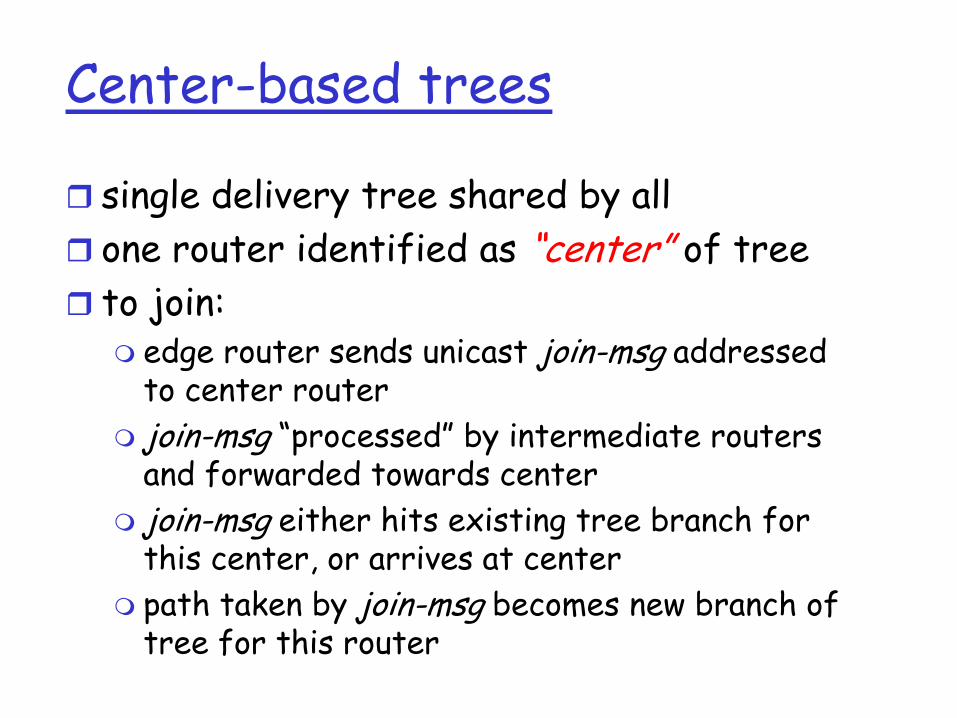
Center-based trees
single delivery tree shared by allone router identified as “center” of treeto join:
edge router sends unicast join-msg addressed to center routerjoin-msg “processed” by intermediate routers and forwarded towards centerjoin-msg either hits existing tree branch for this center, or arrives at centerpath taken by join-msg becomes new branch of tree for this router
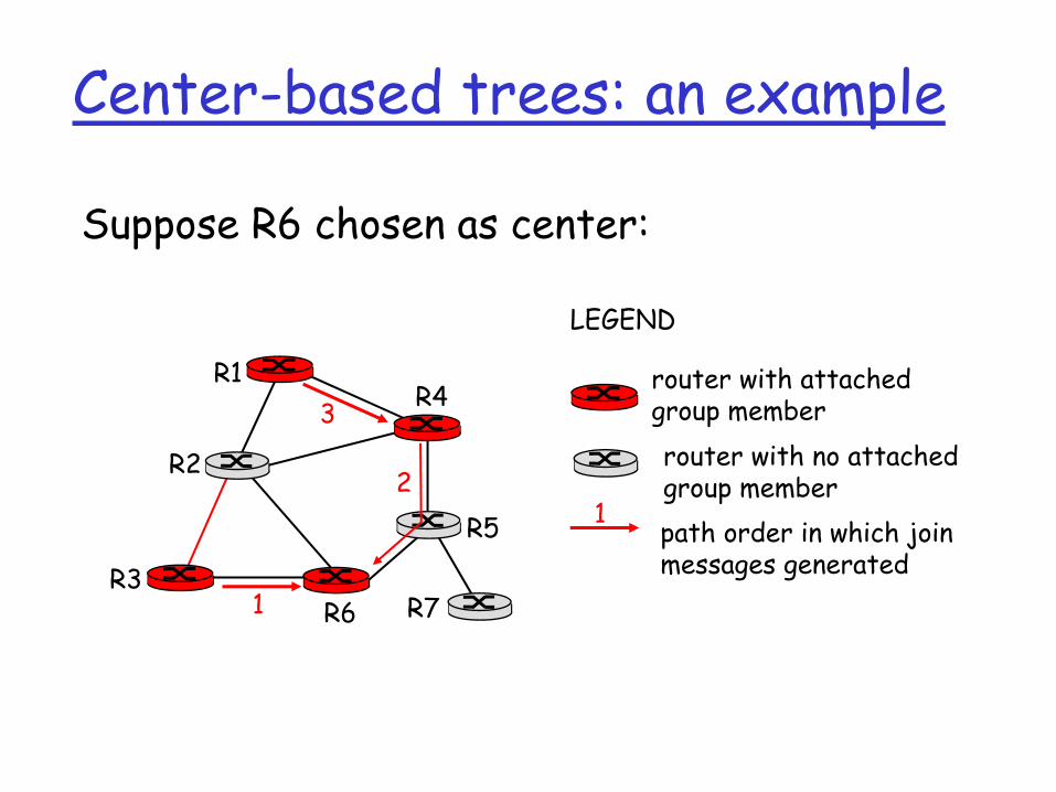
Center-based trees: an example
Suppose R6 chosen as center:
R1
R2
R3
R4
R5
R6 R7
router with attachedgroup memberrouter with no attachedgroup memberpath order in which join messages generated
LEGEND
21
3
1
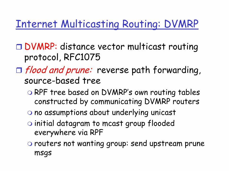
Internet Multicasting Routing: DVMRP
DVMRP: distance vector multicast routing protocol, RFC1075flood and prune: reverse path forwarding, source-based tree
RPF tree based on DVMRP’s own routing tables constructed by communicating DVMRP routers no assumptions about underlying unicastinitial datagram to mcast group flooded everywhere via RPFrouters not wanting group: send upstream prune msgs
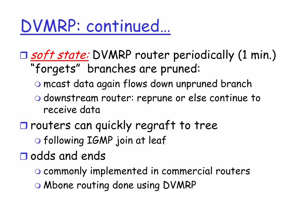
DVMRP: continued…soft state: DVMRP router periodically (1 min.) “forgets” branches are pruned:
mcast data again flows down unpruned branchdownstream router: reprune or else continue to receive data
routers can quickly regraft to tree following IGMP join at leaf
odds and endscommonly implemented in commercial routersMbone routing done using DVMRP

TunnelingQ: How to connect “islands” of multicast
routers in a “sea” of unicast routers?
mcast datagram encapsulated inside “normal” (non-multicast-addressed) datagramnormal IP datagram sent thru “tunnel” via regular IP unicast to receiving mcast routerreceiving mcast router unencapsulates to get mcast datagram
physical topology logical topology
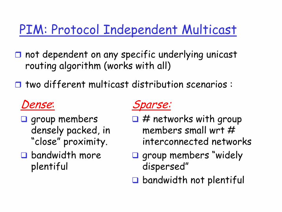
PIM: Protocol Independent Multicast
not dependent on any specific underlying unicast routing algorithm (works with all)
two different multicast distribution scenarios :
Dense:group members densely packed, in “close” proximity.bandwidth more plentiful
Sparse:# networks with group members small wrt # interconnected networksgroup members “widely dispersed”bandwidth not plentiful
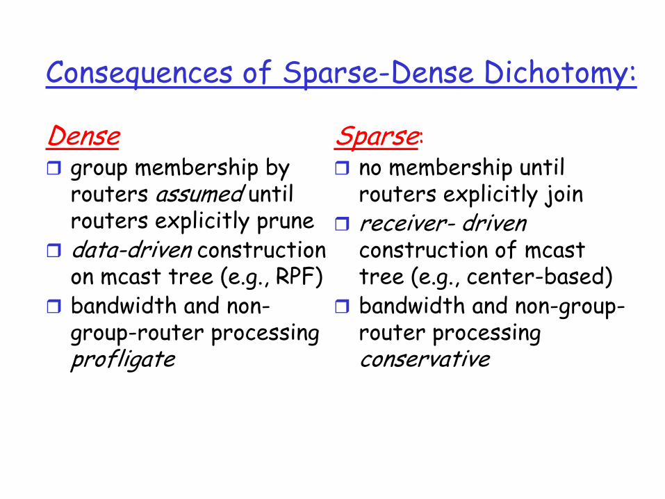
Consequences of Sparse-Dense Dichotomy:
Densegroup membership by routers assumed until routers explicitly prunedata-driven construction on mcast tree (e.g., RPF)bandwidth and non-group-router processing profligate
Sparse:no membership until routers explicitly joinreceiver- drivenconstruction of mcast tree (e.g., center-based)bandwidth and non-group-router processing conservative

PIM- Dense Mode
flood-and-prune RPF, similar to DVMRP butunderlying unicast protocol provides RPF info for incoming datagramless complicated (less efficient) downstream flood than DVMRP reduces reliance on underlying routing algorithmhas protocol mechanism for router to detect it is a leaf-node router
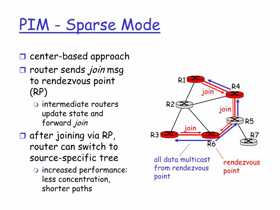
PIM - Sparse Mode
center-based approachrouter sends join msg to rendezvous point (RP)
intermediate routers update state and forward join
after joining via RP, router can switch to source-specific tree
increased performance: less concentration, shorter paths
R1
R2
R3
R4
R5
R6R7
join
join
join
all data multicastfrom rendezvouspoint
rendezvouspoint
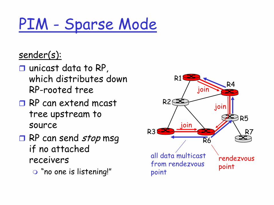
PIM - Sparse Mode
sender(s):unicast data to RP, which distributes down RP-rooted treeRP can extend mcast tree upstream to sourceRP can send stop msg if no attached receivers
“no one is listening!”
R1
R2
R3
R4
R5
R6R7
join
join
join
all data multicastfrom rendezvouspoint
rendezvouspoint