Chapter 4: Naming and addressing - George Mason University
42
1 © 2007 Levente Buttyán and Jean-Pierre Hubaux Security and Cooperation in Wireless Networks http://secowinet.epfl.ch/ Chapter 4: Naming and addressing attacks against naming and addressing: - address stealing - Sybil attack - node replication attack; protection mechanisms: - Cryptographically Generated Addresses - witness based detection of node replication 2/83 Security and Cooperation in Wireless Networks Chapter 4: Naming and addressing Chapter outline 4.1 The future of naming and addressing in the Internet 4.2 Attacks against naming and addressing 4.3 Protection techniques
Transcript of Chapter 4: Naming and addressing - George Mason University
1
© 2007 Levente Buttyán and Jean-Pierre Hubaux
Security and Cooperation in Wireless Networks
http://secowinet.epfl.ch/
Chapter 4: Naming and addressing
attacks against namingand addressing:- address stealing- Sybil attack- node replication attack;protection mechanisms:- CryptographicallyGenerated Addresses- witness based detectionof node replication
2/83Security and Cooperation in Wireless NetworksChapter 4: Naming and addressing
Chapter outline
4.1 The future of naming and addressing in the Internet4.2 Attacks against naming and addressing4.3 Protection techniques

2
3/83Security and Cooperation in Wireless NetworksChapter 4: Naming and addressing
Chapter outline
4.1 The future of naming and addressing in the Internet4.2 Attacks against naming and addressing4.3 Protection techniques
4/83Security and Cooperation in Wireless NetworksChapter 4: Naming and addressing
Introduction
naming and addressing are fundamental for networking– notably, routing protocols need addresses to route packets– services need names in order to be identifiable, discoverable, and
useable
attacks against naming and addressing– address stealing
• adversary starts using an address already assigned to and used by alegitimate node
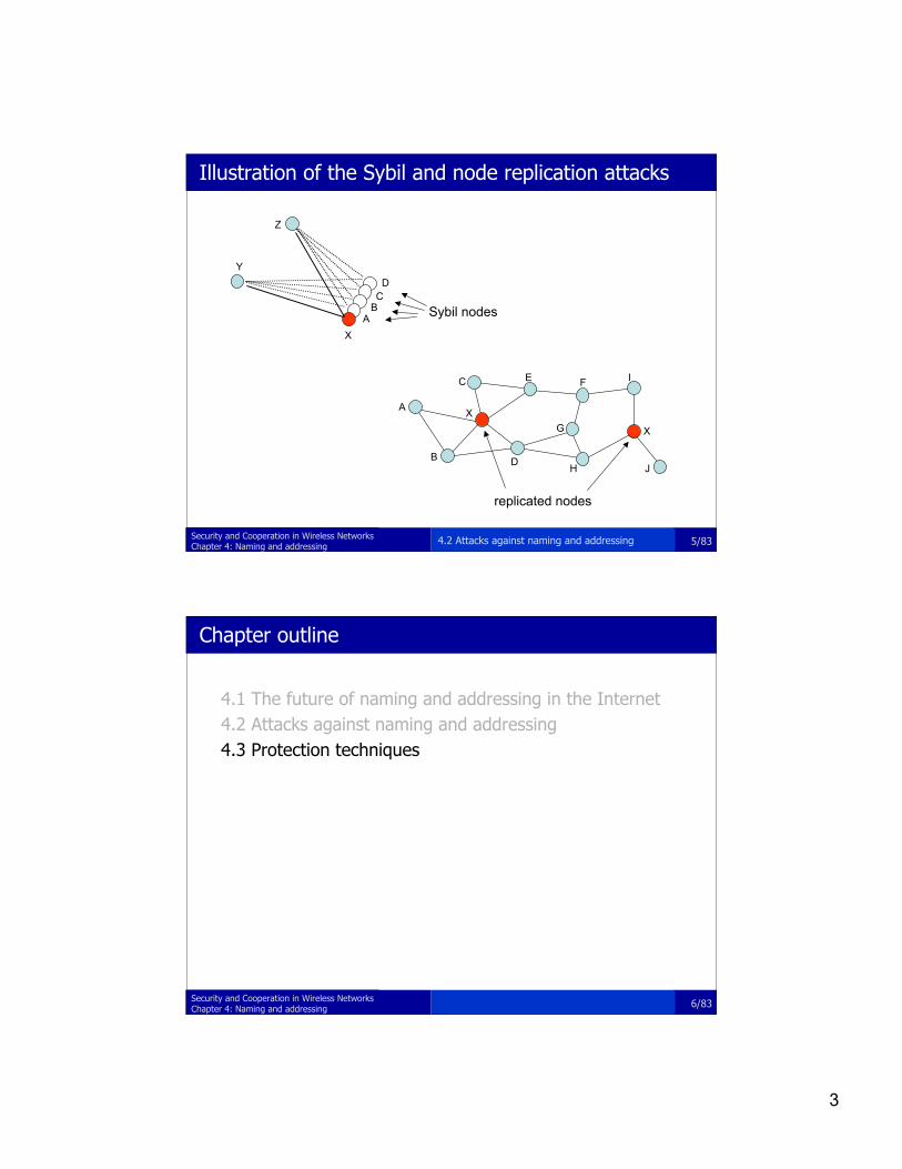
– Sybil attack• a single adversarial node uses several invented addresses• makes legitimate nodes believe that there are many other nodes around
– node replication attack• dual of the Sybil attack• the adversary introduces replicas of a single compromised node using the
same address at different locations of the network
4.2 Attacks against naming and addressing
3
5/83Security and Cooperation in Wireless NetworksChapter 4: Naming and addressing
Illustration of the Sybil and node replication attacks
Sybil nodesABC
D
X
Y
Z
X
X
A
C
B D
E
G
F
H
I
J
replicated nodes
4.2 Attacks against naming and addressing
6/83Security and Cooperation in Wireless NetworksChapter 4: Naming and addressing
Chapter outline
4.1 The future of naming and addressing in the Internet4.2 Attacks against naming and addressing4.3 Protection techniques
4
7/83Security and Cooperation in Wireless NetworksChapter 4: Naming and addressing
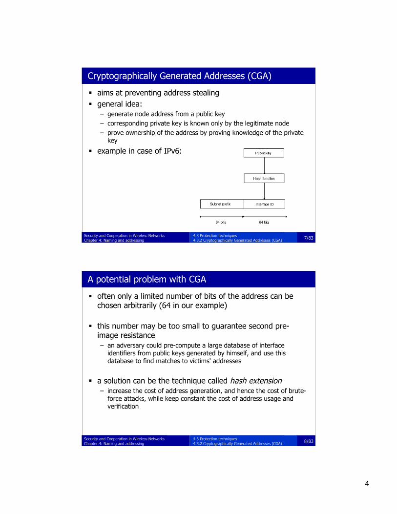
Cryptographically Generated Addresses (CGA)
aims at preventing address stealing general idea:
– generate node address from a public key– corresponding private key is known only by the legitimate node– prove ownership of the address by proving knowledge of the private
key
example in case of IPv6:
4.3 Protection techniques4.3.2 Cryptographically Generated Addresses (CGA)
8/83Security and Cooperation in Wireless NetworksChapter 4: Naming and addressing
A potential problem with CGA
often only a limited number of bits of the address can bechosen arbitrarily (64 in our example)
this number may be too small to guarantee second pre-image resistance– an adversary could pre-compute a large database of interface
identifiers from public keys generated by himself, and use thisdatabase to find matches to victims' addresses
a solution can be the technique called hash extension– increase the cost of address generation, and hence the cost of brute-
force attacks, while keep constant the cost of address usage andverification
4.3 Protection techniques4.3.2 Cryptographically Generated Addresses (CGA)
5
9/83Security and Cooperation in Wireless NetworksChapter 4: Naming and addressing
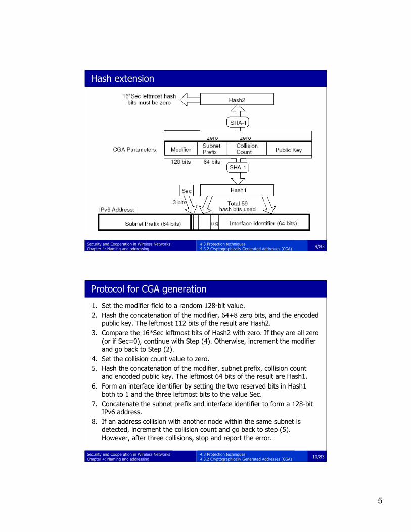
Hash extension
4.3 Protection techniques4.3.2 Cryptographically Generated Addresses (CGA)
10/83Security and Cooperation in Wireless NetworksChapter 4: Naming and addressing
Protocol for CGA generation
1. Set the modifier field to a random 128-bit value.2. Hash the concatenation of the modifier, 64+8 zero bits, and the encoded
public key. The leftmost 112 bits of the result are Hash2.3. Compare the 16*Sec leftmost bits of Hash2 with zero. If they are all zero
(or if Sec=0), continue with Step (4). Otherwise, increment the modifierand go back to Step (2).
4. Set the collision count value to zero.5. Hash the concatenation of the modifier, subnet prefix, collision count
and encoded public key. The leftmost 64 bits of the result are Hash1.6. Form an interface identifier by setting the two reserved bits in Hash1
both to 1 and the three leftmost bits to the value Sec.7. Concatenate the subnet prefix and interface identifier to form a 128-bit
IPv6 address.8. If an address collision with another node within the same subnet is
detected, increment the collision count and go back to step (5).However, after three collisions, stop and report the error.
4.3 Protection techniques4.3.2 Cryptographically Generated Addresses (CGA)
6
11/83Security and Cooperation in Wireless NetworksChapter 4: Naming and addressing
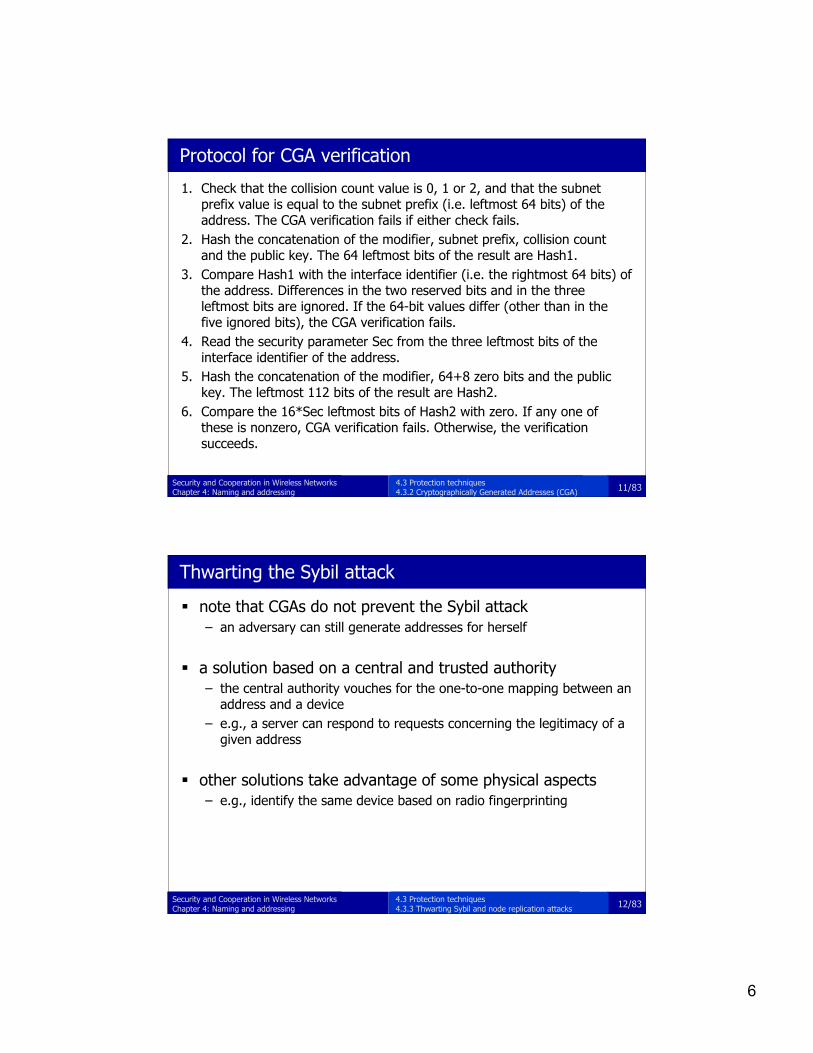
Protocol for CGA verification
1. Check that the collision count value is 0, 1 or 2, and that the subnetprefix value is equal to the subnet prefix (i.e. leftmost 64 bits) of theaddress. The CGA verification fails if either check fails.
2. Hash the concatenation of the modifier, subnet prefix, collision countand the public key. The 64 leftmost bits of the result are Hash1.
3. Compare Hash1 with the interface identifier (i.e. the rightmost 64 bits) ofthe address. Differences in the two reserved bits and in the threeleftmost bits are ignored. If the 64-bit values differ (other than in thefive ignored bits), the CGA verification fails.
4. Read the security parameter Sec from the three leftmost bits of theinterface identifier of the address.
5. Hash the concatenation of the modifier, 64+8 zero bits and the publickey. The leftmost 112 bits of the result are Hash2.
6. Compare the 16*Sec leftmost bits of Hash2 with zero. If any one ofthese is nonzero, CGA verification fails. Otherwise, the verificationsucceeds.
4.3 Protection techniques4.3.2 Cryptographically Generated Addresses (CGA)
12/83Security and Cooperation in Wireless NetworksChapter 4: Naming and addressing
Thwarting the Sybil attack
note that CGAs do not prevent the Sybil attack– an adversary can still generate addresses for herself
a solution based on a central and trusted authority– the central authority vouches for the one-to-one mapping between an
address and a device– e.g., a server can respond to requests concerning the legitimacy of a
given address
other solutions take advantage of some physical aspects– e.g., identify the same device based on radio fingerprinting
4.3 Protection techniques4.3.3 Thwarting Sybil and node replication attacks

7
13/83Security and Cooperation in Wireless NetworksChapter 4: Naming and addressing
Thwarting the node replication attack (1/2)
a centralized solution– each node reports its neighbors’ claimed locations to a central
authority (e.g., the base station in sensor networks)– the central authority detects if the same address appears at two
different locations– assumes location awareness of the nodes
base station
A
B
C
A
D E
A @ (x1, y1)
A @ (x2, y2)
4.3 Protection techniques4.3.3 Thwarting Sybil and node replication attacks
14/83Security and Cooperation in Wireless NetworksChapter 4: Naming and addressing
Thwarting the node replication attack (2/2)
a decentralized variant– neighbors’ claimed location is forwarded to witnesses– witnesses are randomly selected nodes of the network– if a witness detects the same address appearing at two different
locations then it broadcast this information and the replicated nodesare revoked
4.3 Protection techniques4.3.3 Thwarting Sybil and node replication attacks

8
15/83Security and Cooperation in Wireless NetworksChapter 4: Naming and addressing
Analysis of the decentralized variant
total number if nodes is n average number of neighbors is d each neighbor of A forwards A’s location claim with
probability p to g randomly selected witnesses average number of witnesses receiving A’s location claim is
p*d*g if there are L replicas of A, then for the probability of
detection:
Pdet > 1 – exp( - L(L-1)(pdg)2 / 2n)
numerical example:n = 10000, d = 20, g = 100, p = 0.5L = 2 Pdet ~ 0.63L = 3 Pdet ~ 0.95
4.3 Protection techniques4.3.3 Thwarting Sybil and node replication attacks
16/83Security and Cooperation in Wireless NetworksChapter 4: Naming and addressing
Summary
there are various attacks against naming and addressing– address stealing– Sybil attack– node replication attack
decentralization and lack of a central authority renders thedefense against these attacks difficult
proposed solutions (CGA, node replication detection usingwitnesses) provide only probabilistic guarantees– parameters should be chosen carefully
4.4 Summary

9
© 2007 Levente Buttyán and Jean-Pierre Hubaux
Security and Cooperation in Wireless Networks
http://secowinet.epfl.ch/
Chapter 5: Establishment of securityassociations
key establishment insensor networks;key establishment in adhoc networksexploiting- physical contact- vicinity- node mobility;revocation;
18/83Security and Cooperation in Wireless NetworksChapter 4: Naming and addressing
Chapter outline
5.1 Key establishment in sensor networks5.2 Exploiting physical contact5.3 Exploiting mobility5.4 Exploiting the properties of vicinity and of the radio link5.5 Revocation
10
19/83Security and Cooperation in Wireless NetworksChapter 4: Naming and addressing
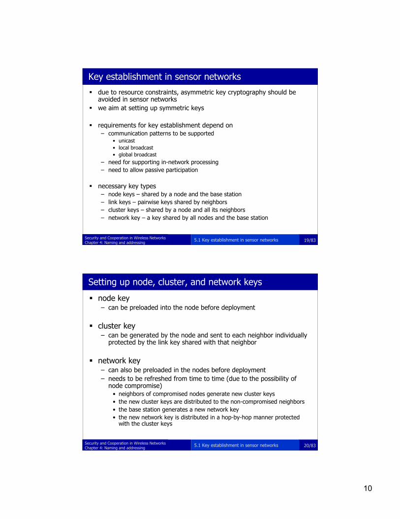
Key establishment in sensor networks
due to resource constraints, asymmetric key cryptography should beavoided in sensor networks
we aim at setting up symmetric keys
requirements for key establishment depend on– communication patterns to be supported
• unicast• local broadcast• global broadcast
– need for supporting in-network processing– need to allow passive participation
necessary key types– node keys – shared by a node and the base station– link keys – pairwise keys shared by neighbors– cluster keys – shared by a node and all its neighbors– network key – a key shared by all nodes and the base station
5.1 Key establishment in sensor networks
20/83Security and Cooperation in Wireless NetworksChapter 4: Naming and addressing
Setting up node, cluster, and network keys
node key– can be preloaded into the node before deployment
cluster key– can be generated by the node and sent to each neighbor individually
protected by the link key shared with that neighbor
network key– can also be preloaded in the nodes before deployment– needs to be refreshed from time to time (due to the possibility of
node compromise)• neighbors of compromised nodes generate new cluster keys• the new cluster keys are distributed to the non-compromised neighbors• the base station generates a new network key• the new network key is distributed in a hop-by-hop manner protected
with the cluster keys
5.1 Key establishment in sensor networks

11
21/83Security and Cooperation in Wireless NetworksChapter 4: Naming and addressing
Design constraints for link key establishment
network lifetime– severe constraints on energy consumption
hardware limits– 8-bit CPU, small memory– large integer arithmetics are infeasible
no tamper resistance– nodes can be compromised– secrets can be leaked
no a priori knowledge of post-deployment topology– it is not known a priori who will be neighbors
gradual deployment– need to add new sensors after deployment
5.1 Key establishment in sensor networks
22/83Security and Cooperation in Wireless NetworksChapter 4: Naming and addressing
Traditional approaches
use of public key crypto (e.g., Diffie-Hellman )– limited computational and energy resources of sensors
use of a trusted key distribution server (Kerberos-like)– base station could play the role of the server– requires routing of key establishment messages to and from the base station
• routing may already need link keys• unequal communication load on the sensors
– base station becomes single point of failure
pre-loaded link keys in sensors– post-deployment topology is unknown– single “mission key” approach
• vulnerable to single node compromise– n -1 keys in each of the n sensors
• excessive memory requirements• gradual deployment is difficult• doesn’t scale
5.1 Key establishment in sensor networks
12
23/83Security and Cooperation in Wireless NetworksChapter 4: Naming and addressing
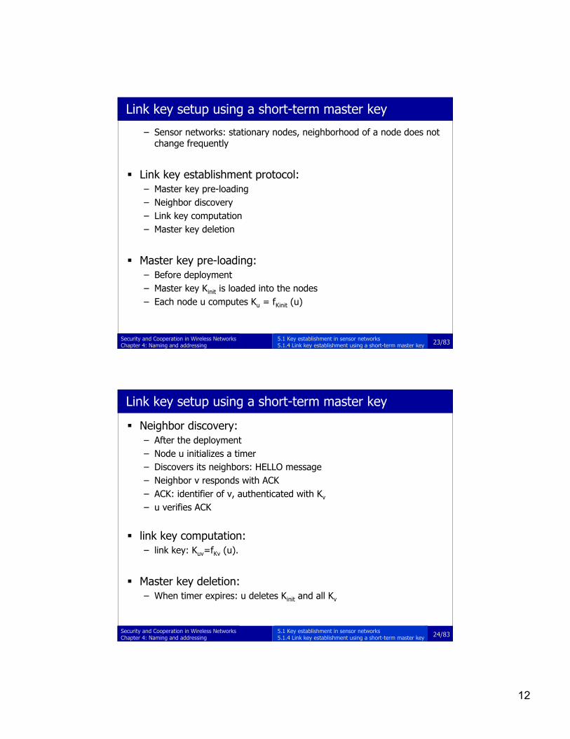
Link key setup using a short-term master key
– Sensor networks: stationary nodes, neighborhood of a node does notchange frequently
Link key establishment protocol:– Master key pre-loading– Neighbor discovery– Link key computation– Master key deletion
Master key pre-loading:– Before deployment– Master key Kinit is loaded into the nodes– Each node u computes Ku = fKinit (u)
5.1 Key establishment in sensor networks5.1.4 Link key establishment using a short-term master key
24/83Security and Cooperation in Wireless NetworksChapter 4: Naming and addressing
Link key setup using a short-term master key
Neighbor discovery:– After the deployment– Node u initializes a timer– Discovers its neighbors: HELLO message– Neighbor v responds with ACK– ACK: identifier of v, authenticated with Kv
– u verifies ACK
link key computation:– link key: Kuv=fKv (u).
Master key deletion:– When timer expires: u deletes Kinit and all Kv
5.1 Key establishment in sensor networks5.1.4 Link key establishment using a short-term master key

13
25/83Security and Cooperation in Wireless NetworksChapter 4: Naming and addressing
Random key pre-distribution – Preliminaries
Given a set S of k elements, we randomly choose two subsets S1 and S2
of m1 and m2 elements, respectively, from S.The probability of S1 ∩ S2 ≠ ∅ is
5.1 Key establishment in sensor networks5.1.5 Link key setup with random key pre-distribution
26/83Security and Cooperation in Wireless NetworksChapter 4: Naming and addressing
The basic random key pre-distribution scheme
initialization phase– a large pool S of unique keys are picked at random– for each node, m keys are selected randomly from S and pre-loaded in the
node (key ring)
direct key establishment phase– after deployment, each node finds out with which of its neighbors it shares a
key (e.g., each node may broadcast the list of its key IDs)– two nodes that discover that they share a key verify that they both actually
posses the key (e.g., execute a challenge-response protocol)
path key establishment phase– neighboring nodes that do not have a common key in their key rings
establish a shared key through a path of intermediaries– each link of the path is secured in the direct key establishment phase
5.1 Key establishment in sensor networks5.1.5 Link key setup with random key pre-distribution
14
27/83Security and Cooperation in Wireless NetworksChapter 4: Naming and addressing
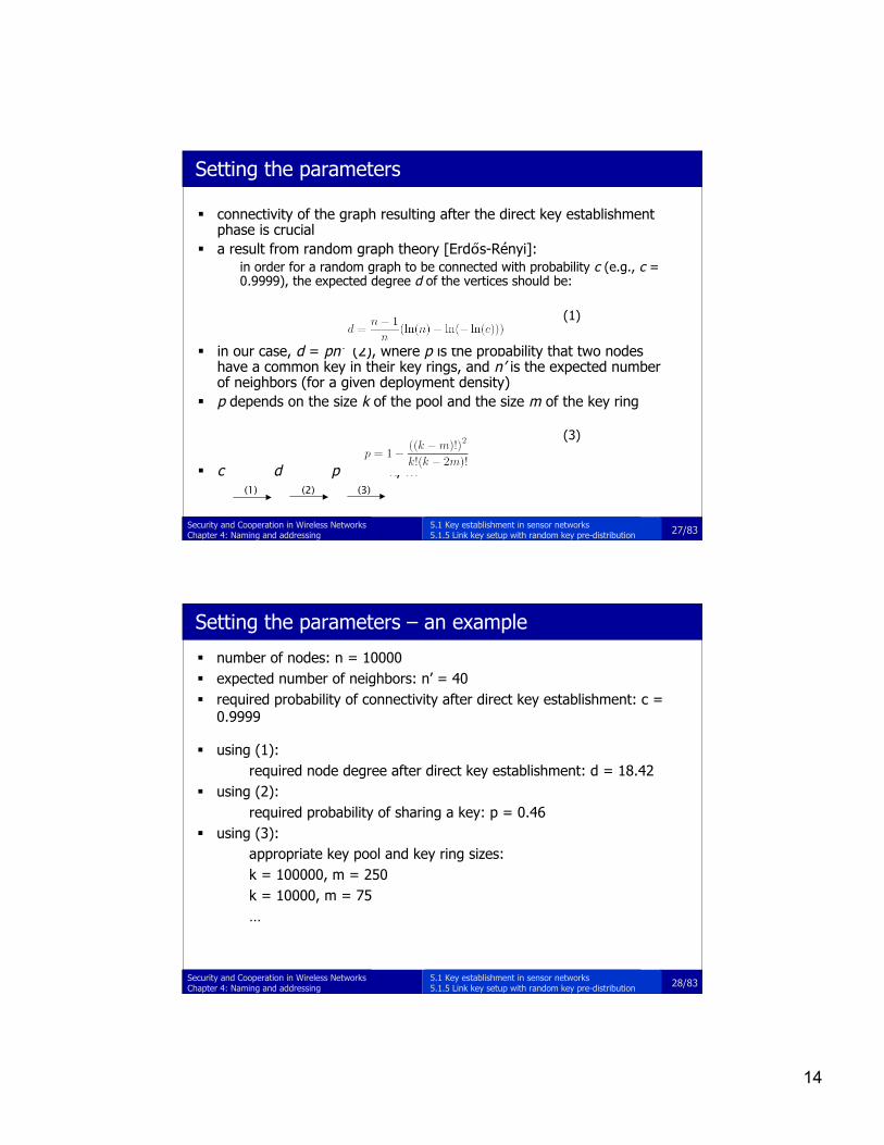
Setting the parameters
connectivity of the graph resulting after the direct key establishmentphase is crucial
a result from random graph theory [Erdős-Rényi]:in order for a random graph to be connected with probability c (e.g., c =0.9999), the expected degree d of the vertices should be:
(1)
in our case, d = pn’ (2), where p is the probability that two nodeshave a common key in their key rings, and n’ is the expected numberof neighbors (for a given deployment density)
p depends on the size k of the pool and the size m of the key ring
(3)
c d p k, m(1) (2) (3)
5.1 Key establishment in sensor networks5.1.5 Link key setup with random key pre-distribution
28/83Security and Cooperation in Wireless NetworksChapter 4: Naming and addressing
Setting the parameters – an example
number of nodes: n = 10000 expected number of neighbors: n’ = 40 required probability of connectivity after direct key establishment: c =
0.9999
using (1):required node degree after direct key establishment: d = 18.42
using (2):required probability of sharing a key: p = 0.46
using (3):appropriate key pool and key ring sizes:k = 100000, m = 250k = 10000, m = 75…
5.1 Key establishment in sensor networks5.1.5 Link key setup with random key pre-distribution

15
29/83Security and Cooperation in Wireless NetworksChapter 4: Naming and addressing
Qualitative analysis
advantages:– parameters can be adopted to special requirements– no need for intensive computation– path key establishment have some overhead …
• decryption and re-encryption at intermediate nodes• communication overhead
– but simulation results show that paths are not very long (2-3 hops)– no assumption on topology– easy addition of new nodes
disadvantages:– node capture affects the security of non-captured nodes too
• if a node is captured, then its keys are compromised• these keys may be used by other nodes too
– if a path key is established through captured nodes, then the path key iscompromised
– no authentication is provided
5.1 Key establishment in sensor networks5.1.5 Link key setup with random key pre-distribution
30/83Security and Cooperation in Wireless NetworksChapter 4: Naming and addressing
Improvements: q-composite rand key pre-distribution
basic idea:– two nodes can set up a shared key if they have at least q common
keys in their key rings– the pairwise key is computed as the hash of all common keys
advantage:– in order to compromise a link key, all keys that have been hashed
together must be compromised
disadvantage:– probability of being able to establish a shared key directly is smaller
(it is less likely to have q common keys, than to have one)– key ring size should be increased (but: memory constraints) or key
pool size should be decreased (but: effect of captured nodes)
5.1 Key establishment in sensor networks5.1.5 Link key setup with random key pre-distribution
16
31/83Security and Cooperation in Wireless NetworksChapter 4: Naming and addressing
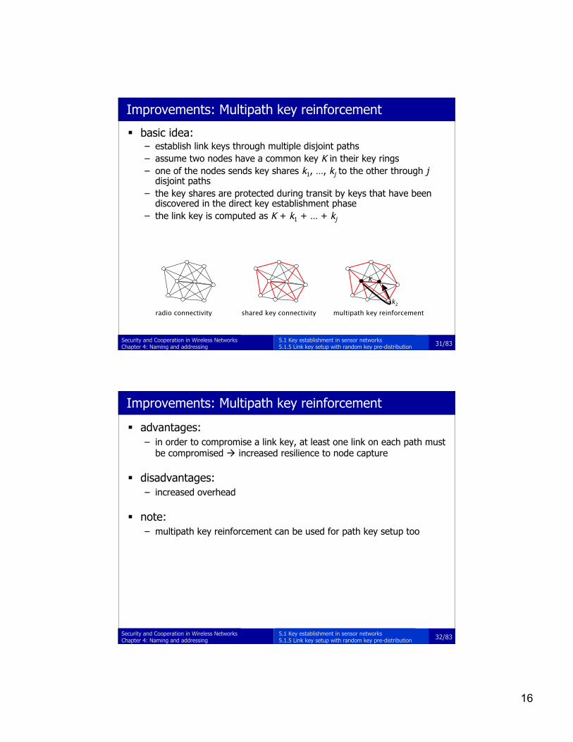
Improvements: Multipath key reinforcement
basic idea:– establish link keys through multiple disjoint paths– assume two nodes have a common key K in their key rings– one of the nodes sends key shares k1, …, kj to the other through j
disjoint paths– the key shares are protected during transit by keys that have been
discovered in the direct key establishment phase– the link key is computed as K + k1 + … + kj
radio connectivity shared key connectivity
k2
K
multipath key reinforcement
5.1 Key establishment in sensor networks5.1.5 Link key setup with random key pre-distribution
32/83Security and Cooperation in Wireless NetworksChapter 4: Naming and addressing
Improvements: Multipath key reinforcement
advantages:– in order to compromise a link key, at least one link on each path must
be compromised increased resilience to node capture
disadvantages:– increased overhead
note:– multipath key reinforcement can be used for path key setup too
5.1 Key establishment in sensor networks5.1.5 Link key setup with random key pre-distribution
17
33/83Security and Cooperation in Wireless NetworksChapter 4: Naming and addressing
Polynomial based key pre-distribution
let f be a bivariate t-degree polynomial over a finite field GF(q), where qis a large prime number, such that f(x, y) = f(y, x)
each node is pre-loaded with a polynomial share f(i, y), where i is the IDof the node
any two nodes i and j can compute a shared key by– i evaluating f(i, y) at point j and obtaining f(i, j), and– j evaluating f(j, y) at point i and obtaining f(j, i) = f(i, j)
this scheme is unconditionally secure and t-collision resistant– any coalition of at most t compromised nodes knows nothing about the
shared keys computed by any pair of non-compromised nodes
any pair of nodes can establish a shared key without communicationoverhead (if they know each other’s ID)
memory requirement of the nodes is (t +1) log(q)
problem: t is limited by the memory constraints of the sensors
5.1 Key establishment in sensor networks5.1.5 Link key setup with random key pre-distribution
34/83Security and Cooperation in Wireless NetworksChapter 4: Naming and addressing
Polynomial based random key pre-distribution
operation:– let S be a pool of bivariate t-degree polynomials– for each node i, we pick a subset of m polynomials from the pool– we pre-load into node i the polynomial shares of these m polynomials
computed at point i– two nodes that have polynomial shares of the same polynomial f can
establish a shared key f(i, j)– if two nodes have no common polynomials, they can establish a shared key
through a path of intermediaries
advantage:– can tolerate the capture of much more than t nodes (t can be smaller, but
each node needs to store m polynomials)• in order to compromise a polynomial, the adversary needs to obtain t + 1
shares of that polynomial• it is very unlikely that t + 1 randomly captured nodes have all selected the same
polynomial from the pool
5.1 Key establishment in sensor networks5.1.5 Link key setup with random key pre-distribution
18
35/83Security and Cooperation in Wireless NetworksChapter 4: Naming and addressing
Matrix based key pre-distribution (Blom’s scheme)
let G be a (t + 1)×n matrix over a finite field GF(q) (where nis the size of the network)
let D be a random (t +1)×(t +1) symmetric matrix overGF(q)
G is public, D is secret
let A = (DG)T and K = AG– K is a symmetric matrix, because
K = AG = (DG)TG = GTDTG = GTDG = GTAT = (AG)T = KT
each node i stores the i-th row of A
any two nodes i and j can compute a shared key Kij– i computes A(i,.)G(.,j) = Kij
– j computes A(j,.)G(.,i) = Kji = Kij
5.1 Key establishment in sensor networks5.1.5 Link key setup with random key pre-distribution
36/83Security and Cooperation in Wireless NetworksChapter 4: Naming and addressing
Matrix based random key pre-distribution
G is as before
D1, …, Dk are random (t +1)×(t +1) symmetric matrices
Av = (DvG)T and {Av} is the pool (of spaces)
for each node i, we pick a random subset of the pool andpre-load in the node the i-th row of the selected matrices(i.e., Av(i,.) for each selected v)
if two nodes i and j both selected a common matrix Av, thenthey can compute a shared key using Blom’s scheme
if two nodes don’t have a common space, they can setup akey through intermediaries
5.1 Key establishment in sensor networks5.1.5 Link key setup with random key pre-distribution

19
37/83Security and Cooperation in Wireless NetworksChapter 4: Naming and addressing
Chapter outline
5.1 Key establishment in sensor networks5.2 Exploiting physical contact5.3 Exploiting mobility5.4 Exploiting the properties of vicinity and of the radio link5.5 Revocation
38/83Security and Cooperation in Wireless NetworksChapter 4: Naming and addressing
Exploiting physical contact
target scenarios– modern home with multiple remotely controlled devices
• DVD, VHS, HiFi, doors, air condition, lights, alarm, …– modern hospital
• mobile personal assistants and medical devices, such as thermometers, bloodpressure meters, …
common in these scenarios– transient associations between devices– physical contact is possible for initialization purposes
the resurrecting duckling security policy– at the beginning, each device has an empty soul– each empty device accepts the first device to which it is physically connected
as its master (imprinting)– during the physical contact, a device key is established– the master uses the device key to execute commands on the device,
including the suicide command– after suicide, the device returns to its empty state and it is ready to be
imprinted again
5.2 Exploiting physical contact

20
39/83Security and Cooperation in Wireless NetworksChapter 4: Naming and addressing
Chapter outline
5.1 Key establishment in sensor networks5.2 Exploiting physical contact5.3 Exploiting mobility5.4 Exploiting the properties of vicinity and of the radio link5.5 Revocation
40/83Security and Cooperation in Wireless NetworksChapter 4: Naming and addressing
Does mobility increase or reduce security ?
Mobility is usually perceived as a major security challenge– Wireless communications– Unpredictable location of the user/node– Sporadic availability of the user/node– Higher vulnerability of the device– Reduced computing capability of the devices
However, very often, people gather and move to increase security– Face to face meetings– Transport of assets and documents– Authentication by physical presence
In spite of the popularity of PDAs and mobile phones, this mobility has not beenexploited to provide digital security
So far, client-server security has been considered as a priority (e-business) Peer-to-peer security is still in its infancy
5.3 Exploiting mobility
21
41/83Security and Cooperation in Wireless NetworksChapter 4: Naming and addressing
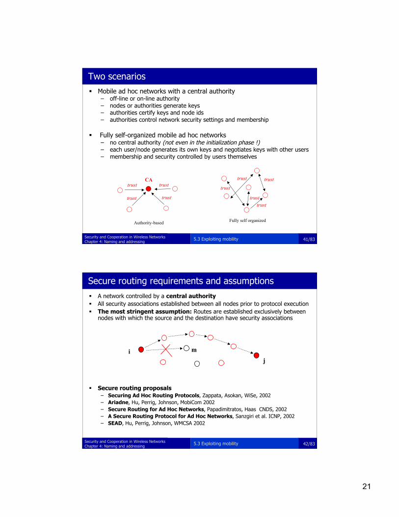
Mobile ad hoc networks with a central authority– off-line or on-line authority– nodes or authorities generate keys– authorities certify keys and node ids– authorities control network security settings and membership
Fully self-organized mobile ad hoc networks– no central authority (not even in the initialization phase !)– each user/node generates its own keys and negotiates keys with other users– membership and security controlled by users themselves
trust trust
trusttrust
CA
trust
trusttrust
trust
trust
Fully self organizedAuthority-based
Two scenarios
5.3 Exploiting mobility
42/83Security and Cooperation in Wireless NetworksChapter 4: Naming and addressing
ij
m
A network controlled by a central authority All security associations established between all nodes prior to protocol execution The most stringent assumption: Routes are established exclusively between
nodes with which the source and the destination have security associations
Secure routing proposals– Securing Ad Hoc Routing Protocols, Zappata, Asokan, WiSe, 2002– Ariadne, Hu, Perrig, Johnson, MobiCom 2002– Secure Routing for Ad Hoc Networks, Papadimitratos, Haas CNDS, 2002– A Secure Routing Protocol for Ad Hoc Networks, Sanzgiri et al. ICNP, 2002– SEAD, Hu, Perrig, Johnson, WMCSA 2002
Secure routing requirements and assumptions
5.3 Exploiting mobility
22
43/83Security and Cooperation in Wireless NetworksChapter 4: Naming and addressing
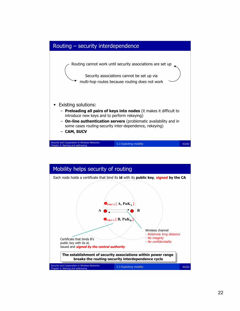
Existing solutions:– Preloading all pairs of keys into nodes (it makes it difficult to
introduce new keys and to perform rekeying)– On-line authentication servers (problematic availability and in
some cases routing-security inter-dependence, rekeying)– CAM, SUCV
Routing cannot work until security associations are set up
Security associations cannot be set up viamulti-hop routes because routing does not work
Routing – security interdependence
5.3 Exploiting mobility
44/83Security and Cooperation in Wireless NetworksChapter 4: Naming and addressing
{ A, PuKA }
Wireless channel - Relatively long distance- No integrity- No confidentiality
σPrKCA
A B
Certificate that binds B’s public key with its id, issued and signed by the central authority
Each node holds a certificate that bind its id with its public key, signed by the CA
{ B, PuKB }σPrKCA
The establishment of security associations within power range breaks the routing-security interdependence cycle
Mobility helps security of routing
5.3 Exploiting mobility

23
45/83Security and Cooperation in Wireless NetworksChapter 4: Naming and addressing
Mobile ad hoc networks with authority-based securitysystems– breaks the routing-security dependence circle– automatic establishment of security associations– no user involvement– associations can be established in power range– only off-line authorities are needed– straightforward re-keying
Advantages of the mobility approach (1/2)
5.3 Exploiting mobility
46/83Security and Cooperation in Wireless NetworksChapter 4: Naming and addressing
Infrared link
(Alice, PuKAlice, XYZ)
(Bob, PuKBob , UVW)
Visual recognition, conscious
establishment of a two-way securityassociation
Secure side channel -Typically short distance (a few meters)- Line of sight required- Ensures integrity- Confidentiality not required
Alice Bob
Fully self-organized scenario
5.3 Exploiting mobility

24
47/83Security and Cooperation in Wireless NetworksChapter 4: Naming and addressing
Binding of the face or person name with his/her public key
: by the Secure Side Channel, the Friend mechanism and the appropriate protocols
Binding of the public key with the NodeId
XYZ : by Cryptographically Generated Addresses Assumption: static allocation of the NodeId: NodeId = h(PuK)
Two binding techniques
5.3 Exploiting mobility
48/83Security and Cooperation in Wireless NetworksChapter 4: Naming and addressing
IR
Colin
Bob(Colin’s friend)
Alice
(Alice, PuKAlice, XYZ)
(Alice, PuKAlice, XYZ)
Colin and Bob are friends:• They have established a Security Association at initialisation• They faithfully share with each other the Security Associations they have set up with other users
Friends mechanism
5.3 Exploiting mobility
25
49/83Security and Cooperation in Wireless NetworksChapter 4: Naming and addressing
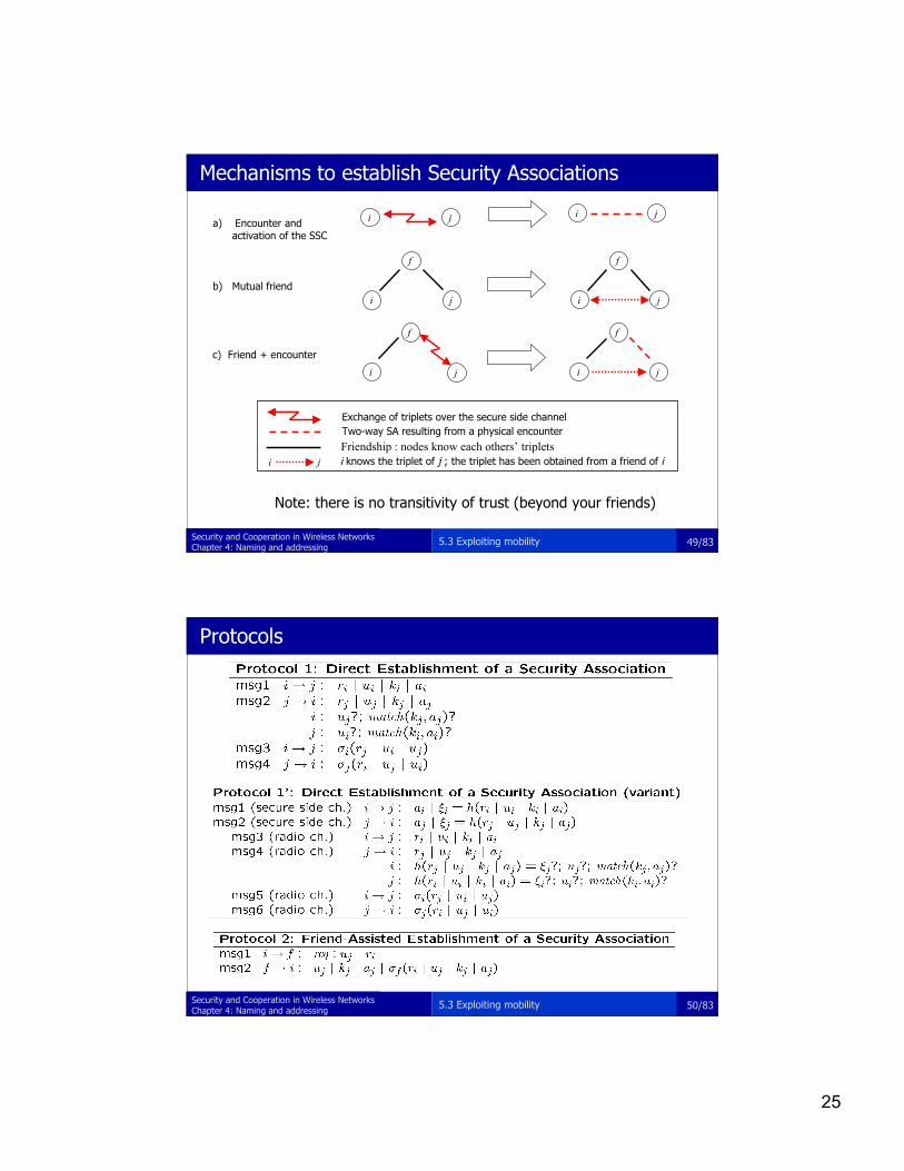
Friendship : nodes know each others’ triplets
Exchange of triplets over the secure side channelTwo-way SA resulting from a physical encounter
i j i knows the triplet of j ; the triplet has been obtained from a friend of i
i
f
j i
f
j
i
f
j i
f
j
i j i ja) Encounter and activation of the SSC
b) Mutual friend
c) Friend + encounter
Note: there is no transitivity of trust (beyond your friends)
Mechanisms to establish Security Associations
5.3 Exploiting mobility
50/83Security and Cooperation in Wireless NetworksChapter 4: Naming and addressing
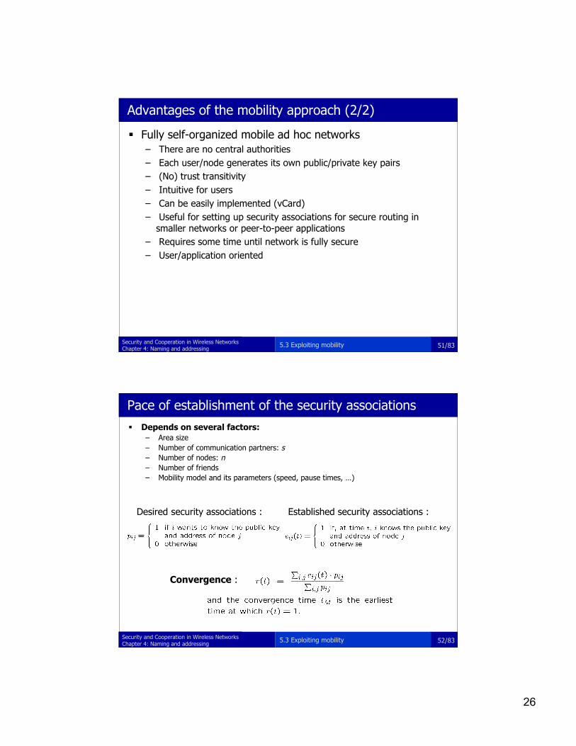
Protocols
5.3 Exploiting mobility
26
51/83Security and Cooperation in Wireless NetworksChapter 4: Naming and addressing
Fully self-organized mobile ad hoc networks– There are no central authorities– Each user/node generates its own public/private key pairs– (No) trust transitivity– Intuitive for users– Can be easily implemented (vCard)– Useful for setting up security associations for secure routing in
smaller networks or peer-to-peer applications– Requires some time until network is fully secure– User/application oriented
Advantages of the mobility approach (2/2)
5.3 Exploiting mobility
52/83Security and Cooperation in Wireless NetworksChapter 4: Naming and addressing
Depends on several factors:– Area size– Number of communication partners: s– Number of nodes: n– Number of friends– Mobility model and its parameters (speed, pause times, …)
Established security associations :Desired security associations :
Convergence :
Pace of establishment of the security associations
5.3 Exploiting mobility
27
53/83Security and Cooperation in Wireless NetworksChapter 4: Naming and addressing
Random walk– discrete time– simple, symmetric random walk– area: Bounded and toroid grids
(33x33, 100x100, 333x333)– number of nodes: 100
Random waypoint– most commonly used in mobile ad hoc networks– continuous time– area size: 1000m x1000m– max speed: 5m/s, 20m/s– pause time: 5s, 100s, 200s– security power range: 5m (SSC), 50m 100m (radio)
Common simulation settings– simulations are run 20 times– confidence interval: 95%
p=1/5
p=1/5
p=1/5p=1/5
p=1/5
Mobility models
5.3 Exploiting mobility
54/83Security and Cooperation in Wireless NetworksChapter 4: Naming and addressing
φ/8
φ/8φ/8
φ/8
φ/8φ/8
φ/8φ/8
1−φAny point on the plane
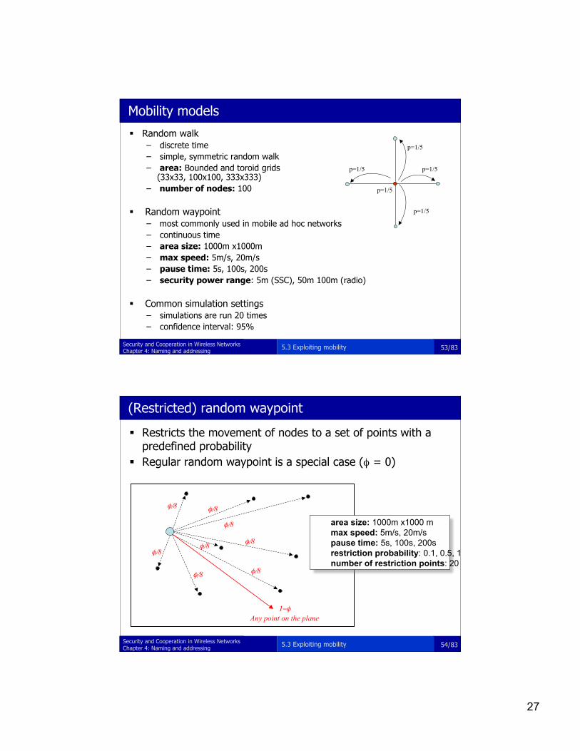
Restricts the movement of nodes to a set of points with apredefined probability
Regular random waypoint is a special case (φ = 0)
area size: 1000m x1000 mmax speed: 5m/s, 20m/spause time: 5s, 100s, 200s restriction probability: 0.1, 0.5, 1 number of restriction points: 20
(Restricted) random waypoint
5.3 Exploiting mobility

28
55/83Security and Cooperation in Wireless NetworksChapter 4: Naming and addressing
Size matters
0
0.1
0.2
0.3
0.4
0.5
0.6
0.7
0.8
0.9
1
100 1000 10000 100000 1000000
time (steps)
percen
tag
e o
f se
cu
rit
y a
sso
cia
tio
ns
s=99, N=100x100 rect., sim. s=99, N=33x33, anal.
tM tM
N=33x33
N=100x100
tM=O(NlogN)
5.3 Exploiting mobility
56/83Security and Cooperation in Wireless NetworksChapter 4: Naming and addressing
Friends help (f+1)
0
0.1
0.2
0.3
0.4
0.5
0.6
0.7
0.8
0.9
1
100 1000 10000 100000 1000000
time (s)
percen
tag
e o
f se
cu
rit
y a
sso
cia
tio
ns
s=99, f=0, pause=100 s, sr=5 m, v=5 m/s s=99, f=2, pause=100 s, sr=5 m, v=5 m/s
s=99, f=0, pause=100 s, sr=5 m, v=20 m/s
5m/s, 2 friends5m/s, 0 friends
20m/s, 0 friends
5.3 Exploiting mobility

29
57/83Security and Cooperation in Wireless NetworksChapter 4: Naming and addressing
Security range matters
0
0.1
0.2
0.3
0.4
0.5
0.6
0.7
0.8
0.9
1
10 100 1000 10000 100000 1000000time (s)
percen
tage o
f se
cu
rit
y a
ssocia
tion
s
f=0, pause=100 s, sr=100 m, f=1 f=0, pause=100 s, sr=5 m, f=1
sec. range 5m
sec. range 100m
5.3 Exploiting mobility
58/83Security and Cooperation in Wireless NetworksChapter 4: Naming and addressing
Meeting points help
0
0.1
0.2
0.3
0.4
0.5
0.6
0.7
0.8
0.9
1
10 100 1000 10000 100000 1000000time (s)
percen
tag
e o
f se
cu
rit
y a
sso
cia
tio
ns
f=0, pause=100 s, sr=5 m f=0, pause=100 s, sr=5 m
f=0, pause=100 s, sr=5 m
random waypoint
restricted random waypoint (0.5)
restricted random waypoint (1)
5.3 Exploiting mobility
30
59/83Security and Cooperation in Wireless NetworksChapter 4: Naming and addressing
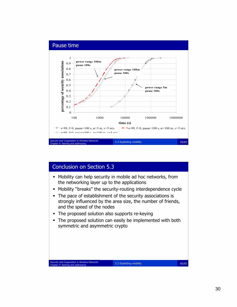
Pause time
0
0.1
0.2
0.3
0.4
0.5
0.6
0.7
0.8
0.9
1
100 1000 10000 100000 1000000
time (s)
per
cen
tage
of
secu
rity
ass
oci
ati
on
s
s=99, f=0, pause=100 s, sr=5 m, v=5 m/s s=99, f=0, pause=100 s, sr=100 m, v=5 m/s
s=99, f=0, pause=300 s, sr=100 m, v=5 m/s
power range 100m
pause 300s
power range 100m
pause 100s
power range 5m
pause 100s
5.3 Exploiting mobility
60/83Security and Cooperation in Wireless NetworksChapter 4: Naming and addressing
Conclusion on Section 5.3
Mobility can help security in mobile ad hoc networks, fromthe networking layer up to the applications
Mobility “breaks” the security-routing interdependence cycle The pace of establishment of the security associations is
strongly influenced by the area size, the number of friends,and the speed of the nodes
The proposed solution also supports re-keying The proposed solution can easily be implemented with both
symmetric and asymmetric crypto
5.3 Exploiting mobility
31
61/83Security and Cooperation in Wireless NetworksChapter 4: Naming and addressing
Chapter outline
5.1 Key establishment in sensor networks5.2 Exploiting physical contact5.3 Exploiting mobility5.4 Exploiting the properties of vicinity and of the radio link5.5 Revocation
62/83Security and Cooperation in Wireless NetworksChapter 4: Naming and addressing
Exploiting vicinity
problem– how to establish a shared key between two PDAs?
assumptions– no CA, no KDC– PDAs can use short range radio communications (e.g., Bluetooth)– PDAs have a display– PDAs are held by human users
idea– use the Diffie-Hellman key agreement protocol– ensure key authentication by the human users
5.4 Exploiting vicinity and properties of the radio link

32
63/83Security and Cooperation in Wireless NetworksChapter 4: Naming and addressing
Diffie-Hellman with String Comparison
theorem: the probability that an attacker succeeds against theabove protocol is bounded by nγ2-k, where n is the totalnumber of users, γ is the maximum number of sessions thatany party can participate in, and k is the security parameter
5.4 Exploiting vicinity and properties of the radio link
64/83Security and Cooperation in Wireless NetworksChapter 4: Naming and addressing
Integrity Codes
is it possible to rely on the radio channel only?
assumption– it is possible to implement a channel with the following property:
• bit 0 can be turned into bit 1• bit 1 cannot be turned into bit 0
– an example:• bit 1 = presence of random signal (~noise)• bit 0 = no signal at all
i(ntegrity)-codes– each codeword has the same number of 0s and 1s– such a codeword cannot be modified in an unnoticeable way– encoding messages with i-codes ensures the integrity of the
communications Man-in-the-Middle is excluded
5.4 Exploiting vicinity and properties of the radio link
33
65/83Security and Cooperation in Wireless NetworksChapter 4: Naming and addressing
Chapter outline
5.1 Key establishment in sensor networks5.2 Exploiting physical contact5.3 Exploiting mobility5.4 Exploiting the properties of vicinity and of the radio link5.5 Revocation
66/83Security and Cooperation in Wireless NetworksChapter 4: Naming and addressing
Revocation
methods of revocation proposed in the IEEE P1609.2:– distribution of CRLs (Certificate Revocation Lists)– Using short-lived certificates
Drawbacks:– CRLs can be very long– Short lifetime creates a vulnerability window
Solution: based on– RTPD (Revocation Protocol of the Tamper-Proof Device)– RCCRL (Revocation protocol using Compressed Certificate Revocation
Lists)– DRP (Distributed Revocation Protocol).
5.5 Revocation
34
67/83Security and Cooperation in Wireless NetworksChapter 4: Naming and addressing
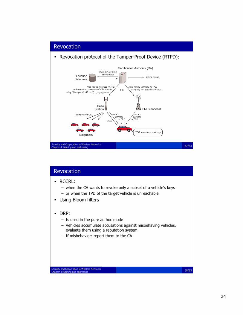
Revocation
Revocation protocol of the Tamper-Proof Device (RTPD):
68/83Security and Cooperation in Wireless NetworksChapter 4: Naming and addressing
Revocation
RCCRL:– when the CA wants to revoke only a subset of a vehicle's keys– or when the TPD of the target vehicle is unreachable
Using Bloom filters
DRP:– Is used in the pure ad hoc mode– Vehicles accumulate accusations against misbehaving vehicles,
evaluate them using a reputation system– If misbehavior: report them to the CA

35
69/83Security and Cooperation in Wireless NetworksChapter 4: Naming and addressing
Summary
it is possible to establish pairwise shared keys in ad hocnetworks without a globally trusted third party
mobility, secure side channels, and friends are helpful in sensor networks, we need different types of keys
– node keys, cluster keys, and network keys can be establishedrelatively easily using the technique of key pre-loading and usingalready established link keys
– link keys can be established using a short-term master key or withthe technique of random key pre-distribution
5.6 Summary
70/83Security and Cooperation in Wireless NetworksChapter 4: Naming and addressing
Chapter 7: Secure routing in multi-hop wireless networks
ad hoc network routingprotocols;routing security in sensornetworks;
36
71/83Security and Cooperation in Wireless NetworksChapter 4: Naming and addressing
Chapter outline
7.1 Routing protocols for mobile ad hoc networks7.5 Secure routing in sensor networks
72/83Security and Cooperation in Wireless NetworksChapter 4: Naming and addressing
Ad hoc network routing protocols
topology-based protocols– proactive
• distance vector based (e.g., DSDV)• link-state (e.g., OLSR)
– reactive (on-demand)• distance vector based (e.g., AODV)• source routing (e.g., DSR)
position-based protocols• greedy forwarding (e.g., GPSR, GOAFR)• restricted directional flooding (e.g., DREAM, LAR)
hybrid approaches
7.1 Routing protocols for mobile ad hoc networks
37
73/83Security and Cooperation in Wireless NetworksChapter 4: Naming and addressing
Example: Dynamic Source Routing (DSR)
on-demand source routing protocol
two components:– route discovery
• used only when source S attempts to send a packet to destination D• based on flooding of Route Requests (RREQ) and returning Route Replies (RREP)
– route maintenance• makes S able to detect route errors (e.g., if a link along that route no longer
works)
7.1 Routing protocols for mobile ad hoc networks
74/83Security and Cooperation in Wireless NetworksChapter 4: Naming and addressing
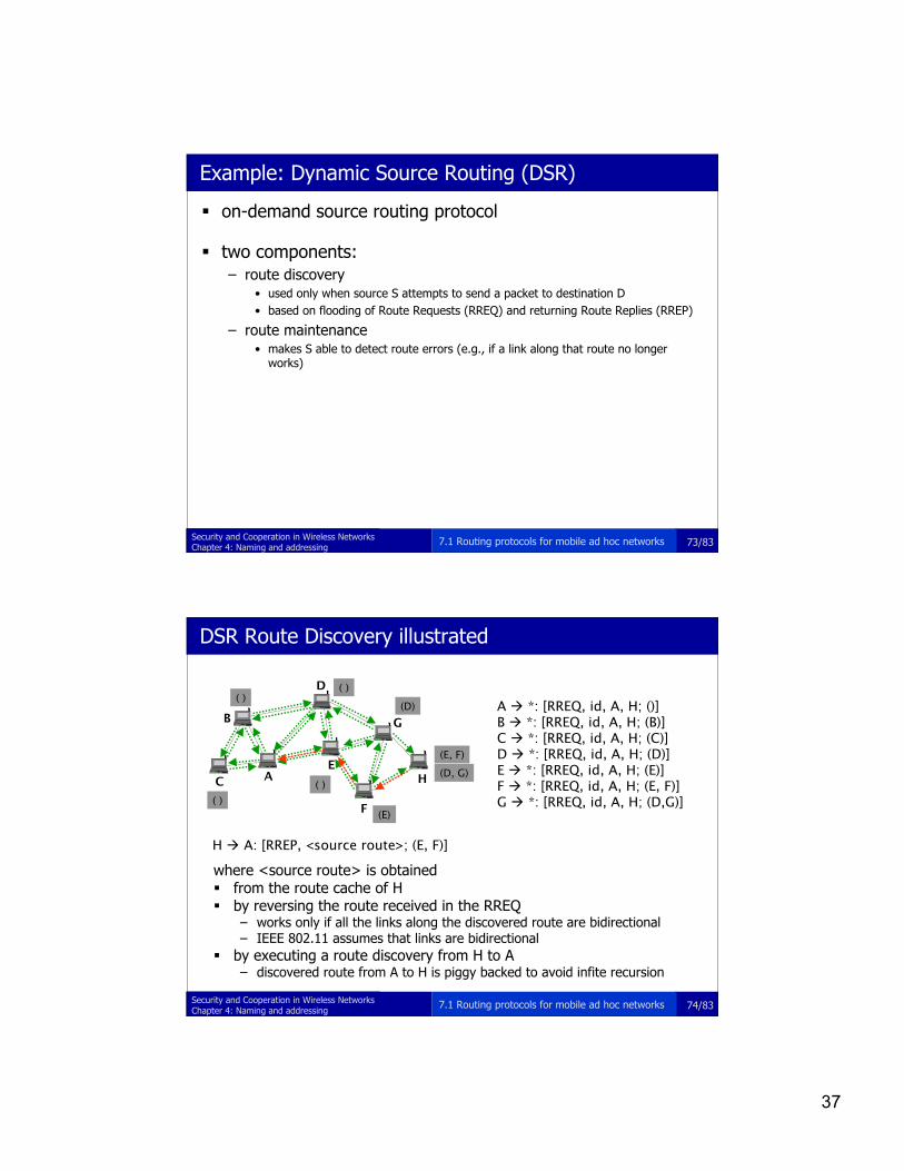
DSR Route Discovery illustrated
where <source route> is obtained from the route cache of H by reversing the route received in the RREQ
– works only if all the links along the discovered route are bidirectional– IEEE 802.11 assumes that links are bidirectional
by executing a route discovery from H to A– discovered route from A to H is piggy backed to avoid infite recursion
A
B
C
D
E
F
G
H
A *: [RREQ, id, A, H; ()]B *: [RREQ, id, A, H; (B)]C *: [RREQ, id, A, H; (C)]D *: [RREQ, id, A, H; (D)]E *: [RREQ, id, A, H; (E)]F *: [RREQ, id, A, H; (E, F)]G *: [RREQ, id, A, H; (D,G)]( )
( )( )
( )
(D)
(E)
(D, G)
(E, F)
H A: [RREP, <source route>; (E, F)]
7.1 Routing protocols for mobile ad hoc networks

38
75/83Security and Cooperation in Wireless NetworksChapter 4: Naming and addressing
Example: Ad-hoc On-demand Distance Vector routing (AODV)
on-demand distance vector routing
uses sequence numbers to ensure loop-freedom and todetect out-of-date routing information
operation is similar to that of DSR but the nodes maintainrouting tables instead of route caches
a routing table entry contains the following:– destination identifier– number of hops needed to reach the destination– identifier of the next hop towards the destination– list of precursor nodes (that may forward packets to the destination
via this node)– destination sequence number
7.1 Routing protocols for mobile ad hoc networks
76/83Security and Cooperation in Wireless NetworksChapter 4: Naming and addressing
AODV Route Discovery illustrated
A
B
C
D
E
F
G
H
A *: [RREQ, id, A, H, 0, snA, snH]B *: [RREQ, id, A, H, 1, snA, snH]C *: [RREQ, id, A, H, 1, snA, snH]D *: [RREQ, id, A, H, 1, snA, snH]E *: [RREQ, id, A, H, 1, snA, snH]F *: [RREQ, id, A, H, 2, snA, snH]G *: [RREQ, id, A, H, 2, snA, snH]
H F: [RREP, A, H, 0, sn’H]F E: [RREP, A, H, 1, sn’H]E A: [RREP, A, H, 2, sn’H]
(A, 0, -, -, snA)
(A, 0, -, -, snA)
(A, 0, -, -, snA)
(A, 0, -, -, snA)
(A, 1, D, -, snA)
(A, 1, E, -, snA)
(A, 2, F, -, snA)
(H, 0, -, E, sn’H)
(A, 1, E, H, snA)(H, 1, F, A, sn’H)
(A, 0, -, F, snA)(H, 2, E, -, sn’H)
7.1 Routing protocols for mobile ad hoc networks
39
77/83Security and Cooperation in Wireless NetworksChapter 4: Naming and addressing
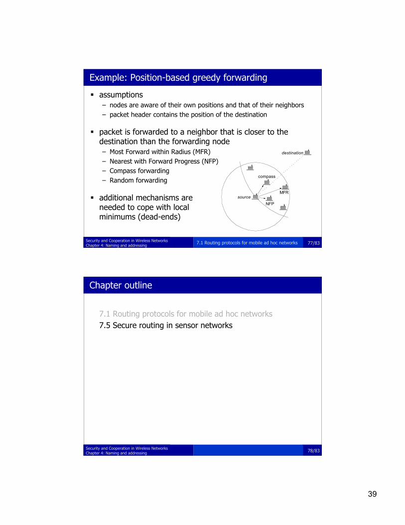
Example: Position-based greedy forwarding
assumptions– nodes are aware of their own positions and that of their neighbors– packet header contains the position of the destination
packet is forwarded to a neighbor that is closer to thedestination than the forwarding node– Most Forward within Radius (MFR)– Nearest with Forward Progress (NFP)– Compass forwarding– Random forwarding
additional mechanisms areneeded to cope with localminimums (dead-ends)
compass
MFR
NFP
source
destination
7.1 Routing protocols for mobile ad hoc networks
78/83Security and Cooperation in Wireless NetworksChapter 4: Naming and addressing
Chapter outline
7.1 Routing protocols for mobile ad hoc networks7.5 Secure routing in sensor networks

40
79/83Security and Cooperation in Wireless NetworksChapter 4: Naming and addressing
How are sensor networks different?
communication patterns– sensors to base station (many-to-one)– base station to sensors (one-to-many)
limited mobility– sensor nodes are mainly static– topology can change due to node and link failures– much less dynamicity than in ad hoc networks of mobile computers
resource constraints– sensor nodes are much more constrained in terms of resources
infrastructure support– the base station can act as a trusted entity
7.5 Secure routing in sensor networks
80/83Security and Cooperation in Wireless NetworksChapter 4: Naming and addressing
TinyOS beaconing
base station(sink)
sensor
7.5 Secure routing in sensor networks

41
81/83Security and Cooperation in Wireless NetworksChapter 4: Naming and addressing
Authenticated TinyOS beaconing
since beacon messages are not authenticated, an adversarycan initiate the route update process and become the root ofthe established tree
in order to prevent this, the base station should authenticatethe beacon– needs broadcast authentication– due to resource constraints, symmetric key crypto should be used– a possible solution is TESLA
this does not entirely solve the problem …
7.5 Secure routing in sensor networks
82/83Security and Cooperation in Wireless NetworksChapter 4: Naming and addressing
Authenticated TinyOS beaconing
intermediate nodes are not authenticated an adversary can use spoofing to create a routing loop
adversary
u
v
in the name of vroute update
7.5 Secure routing in sensor networks

42
83/83Security and Cooperation in Wireless NetworksChapter 4: Naming and addressing
Summary
routing is a fundamental function in networking, hence, an ideal targetfor attacks
attacks against routing aim at– increasing adversarial control over the communications between some nodes;– degrading the quality of the service provided by the network;– increasing the resource consumption of some nodes (e.g., CPU, memory, or
energy)
many attacks (but not all!) can be prevented by authenticating routingcontrol messages
it is difficult to protect the mutable parts of control messages special attacks (e.g., tunnels and rushing) needs special protection
mechanisms several secured ad hoc network routing protocols have been proposed some of them have weaknesses that are exploitable by attacks
7.6 Summary