Chapter 4 DYNAMICS OF FLUID FLOWbu.edu.eg/portal/uploads/Engineering, Shoubra/Civil...
20
Faculty Of Engineering at Shobra 2 nd Year Civil - 2016 Fluid Mechanics, CVE 214 Dr. Alaa El-Hazek 28 Chapter 4 DYNAMICS OF FLUID FLOW 4-1 Types of Energy 4-2 Euler’s Equation 4-3 Bernoulli’s Equation 4-4 Total Energy Line (TEL) and Hydraulic Grade Line (HGL) 4-5 Applications of Bernoulli's Equation (Venturi meter – Orifice meter – Pitot Tube) For the dynamics of fluid flow, or hydrodynamics, the fluid motion is studied including the force and energy considerations. 4-1 Types of Energy: I- Potential Energy: It is the energy possessed by a fluid particle due to its position with respect to an arbitrary datum. II- Pressure Energy: It is the energy possessed by a fluid particle due to its pressure. III- Kinetic Energy: It is the energy possessed by a fluid particle due to its motion or velocity. 4-2 Euler’s Equation: Assumptions and Limitations: 1- The fluid is ideal (non-viscous or no friction losses). 2- The fluid is incompressible ( is constant). 3- The flow is steady. 4- The velocity of flow is uniform over the section. 5- Only the gravity and pressure forces are considered. The Equation: For a steady flow of an ideal fluid, consider an element AB of the fluid, as shown in the figure.
Transcript of Chapter 4 DYNAMICS OF FLUID FLOWbu.edu.eg/portal/uploads/Engineering, Shoubra/Civil...

Faculty Of Engineering at Shobra 2nd Year Civil - 2016
Fluid Mechanics, CVE 214 Dr. Alaa El-Hazek
28
Chapter 4
DYNAMICS OF FLUID FLOW
4-1 Types of Energy 4-2 Euler’s Equation 4-3 Bernoulli’s Equation
4-4 Total Energy Line (TEL) and Hydraulic Grade Line (HGL)
4-5 Applications of Bernoulli's Equation (Venturi meter – Orifice meter – Pitot Tube)
For the dynamics of fluid flow, or hydrodynamics, the fluid motion is studied
including the force and energy considerations.
4-1 Types of Energy:
I- Potential Energy:
It is the energy possessed by a fluid particle due to its position with respect to
an arbitrary datum.
II- Pressure Energy:
It is the energy possessed by a fluid particle due to its pressure.
III- Kinetic Energy:
It is the energy possessed by a fluid particle due to its motion or velocity.
4-2 Euler’s Equation:
Assumptions and Limitations:
1- The fluid is ideal (non-viscous or no friction losses).
2- The fluid is incompressible ( is constant).
3- The flow is steady.
4- The velocity of flow is uniform over the section.
5- Only the gravity and pressure forces are considered.
The Equation:
For a steady flow of an ideal fluid, consider an element AB of the fluid, as
shown in the figure.
Faculty Of Engineering at Shobra 2nd Year Civil - 2016
Fluid Mechanics, CVE 214 Dr. Alaa El-Hazek
29
ds, dA: length and cross sectional area of the fluid element.
dW : Weight of the fluid element.
p : Pressure of the fluid element at A.
p + dp: Pressure of the fluid element at B.
Applying Newton’s second law of motion in the direction of flow:
F = M a
F = P dA - (P + dP) dA - dW cos
dW = M g = V g = dA ds g
Thus, F = - dP dA - dA ds g cos ................. (1)
M a = V a = dA ds a
And, a = dv = dv x ds = dv v
dt ds dt ds
a ds = v dv
Then, M a = dA v dv .................................... (2)
(1) = (2), - dP dA - dA ds g cos = dA v dv
dA, - dP - g ds cos = v dv
But, ds cos = dz
Thus, - dP - g dz = v dv
g dz + dP + v dv = 0
( = g ), we get,
dz + dP + v dv = 0
g
Faculty Of Engineering at Shobra 2nd Year Civil - 2016
Fluid Mechanics, CVE 214 Dr. Alaa El-Hazek
30
4-3 Bernoulli’s Equation:
Integrating Euler’s equation, we get Bernoulli’s equation.
Z + (P / ) + (v2 / 2g) = Constant
Where, Z : Potential energy per unit weight of fluid, or potential head with
respect to an arbitrary datum.
P / : Pressure energy per unit weight of fluid, or pressure head.
v2/2g : Kinetic energy per unit weight of fluid, or velocity head.
Applying Bernoulli’s equation between two points along the flow of the
fluid, we get:
Z1 + (P/)1 + (v2/2g)1 = Z2 + (P/)2 + (v2/2g)2 = Constant
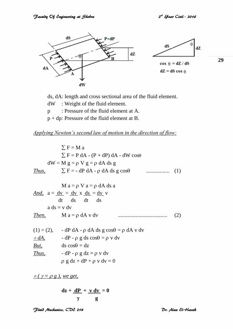
4-4 Total Energy Line (TEL) and Hydraulic Grade Line (HGL):
Total Energy = Potential Head + Pressure Head + Velocity Head
Piezometeric Head = Potential Head + Pressure Head
For different sections along the fluid flow,
an arbitrary datum is chosen. The potential,
pressure, and velocity heads are assigned on
a vertical line through each section above
the datum using adequate scale.
The line between points representing the
total head is the total energy line (TEL).
The line between points representing the
piezometeric head is the hydraulic grade
line (HGL).
Faculty Of Engineering at Shobra 2nd Year Civil - 2016
Fluid Mechanics, CVE 214 Dr. Alaa El-Hazek
31
Notes:
1- Bernoulli’s Equation for a Real Fluid Flow:
The real fluid has viscosity that resists the flow. So; a part of the total energy
of flow is lost due to the friction. This head loss is denoted by hL.
Z1 + (P/)1 + (v2 /2g) 1 = Z2 + (P/)2 + (v2 /2g)2 + hL
2- Direction of the Flow:
The fluid flows from the point of high total energy to that of low total energy.
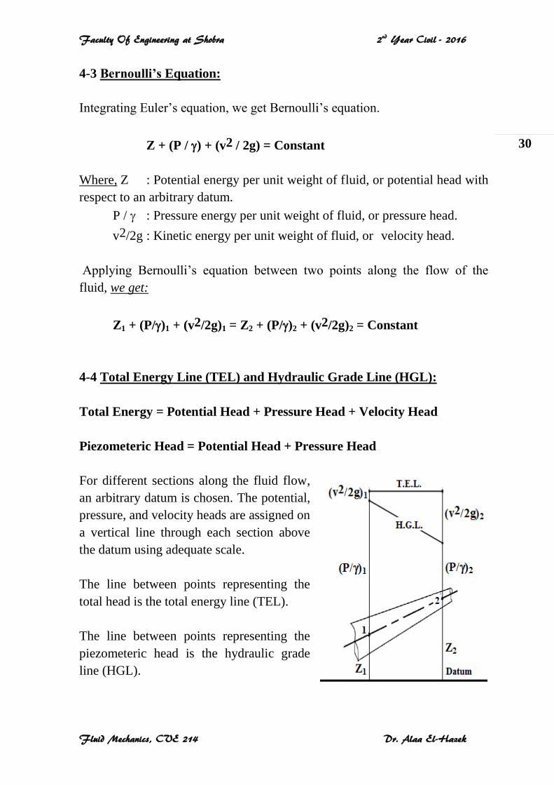
Example 1:
As shown in the figure, the diameter
of a pipe changes from 20 cm at a
section 3 m above datum, to 5 cm at
another section 5 m above the datum.
At the second section, the pressure of
water is 1.2 kg/cm2 and the velocity of
flow is 16 m/sec.
Determine the pressure at the first section?
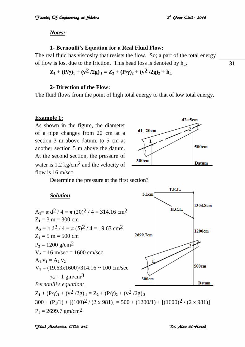
Solution
A1= π d2 / 4 = π (20)2 / 4 = 314.16 cm2
Z1 = 3 m = 300 cm
A2 = π d2 / 4 = π (5)2 / 4 = 19.63 cm2
Z2 = 5 m = 500 cm
P2 = 1200 g/cm2
V2 = 16 m/sec = 1600 cm/sec
A1 v1 = A2 v2
V1 = (19.63x1600)/314.16 ~ 100 cm/sec
w = 1 gm/cm3
Bernoulli's equation:
Z1 + (P/)1 + (v2 /2g) 1 = Z2 + (P/)2 + (v2 /2g) 2
300 + (P1/1) + [(100)2 / (2 x 981)] = 500 + (1200/1) + [(1600)2 / (2 x 981)]
P1 = 2699.7 gm/cm2
Faculty Of Engineering at Shobra 2nd Year Civil - 2016
Fluid Mechanics, CVE 214 Dr. Alaa El-Hazek
32
4-5 Applications of Bernoulli's Equation:
There are many practical applications of Bernoulli’s equation. We shall
consider only three applications for flow measurements in pipes, using the
three hydraulic devices: venturi meter, orifice meter, and pitot tube.
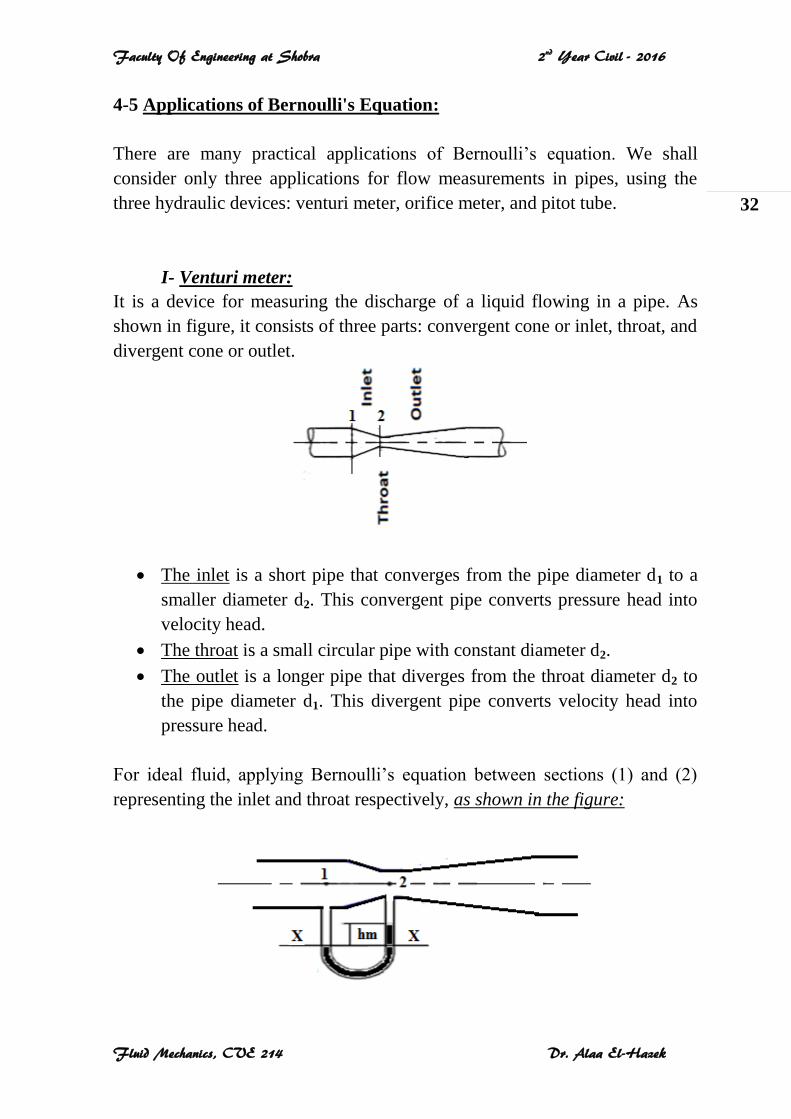
I- Venturi meter:
It is a device for measuring the discharge of a liquid flowing in a pipe. As
shown in figure, it consists of three parts: convergent cone or inlet, throat, and
divergent cone or outlet.
The inlet is a short pipe that converges from the pipe diameter d1 to a
smaller diameter d2. This convergent pipe converts pressure head into
velocity head.
The throat is a small circular pipe with constant diameter d2.
The outlet is a longer pipe that diverges from the throat diameter d2 to
the pipe diameter d1. This divergent pipe converts velocity head into
pressure head.
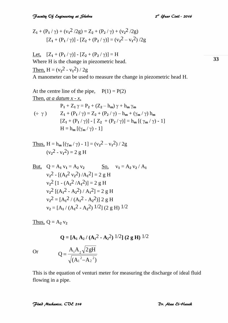
For ideal fluid, applying Bernoulli’s equation between sections (1) and (2)
representing the inlet and throat respectively, as shown in the figure:
Faculty Of Engineering at Shobra 2nd Year Civil - 2016
Fluid Mechanics, CVE 214 Dr. Alaa El-Hazek
33
Z1 + (P1 / ) + (v12 /2g) = Z2 + (P2 / ) + (v2
2 /2g)
[Z1 + (P1 / )] - [Z2 + (P2 / )] = (v22 – v1
2) /2g
Let, [Z1 + (P1 / )] - [Z2 + (P2 / )] = H
Where H is the change in piezometric head.
Then, H = (v22 - v1
2) / 2g
A manometer can be used to measure the change in piezometric head H.
At the centre line of the pipe, P(1) = P(2)
Then, at a datum x - x,
P1 + Z1 = P2 + (Z2 – hm) + hm m
( ) Z1 + (P1 / ) = Z2 + (P2 / ) – hm + (m / ) hm
[Z1 + (P1 / )] - [ Z2 + (P2 / )] = hm [( m / ) - 1]
H = hm [(m / ) - 1]
Thus, H = hm [(m / ) - 1] = (v22 – v1
2) / 2g
(v22 - v1
2) = 2 g H
But, Q = A1 v1 = A2 v2 So, v1 = A2 v2 / A1
v22 - [(A2
2 v22) /A1
2] = 2 g H
v22 [1 - (A2
2 /A12)] = 2 g H
v22 [(A1
2 - A22) / A1
2] = 2 g H
v22 = [A1
2 / (A12 - A2
2)] 2 g H
v2 = [A1 / (A12 - A2
2) 1/2] (2 g H) 1/2
Thus, Q = A2 v2
Q = [A1 A2 / (A12 - A2
2) 1/2] (2 g H) 1/2
Or
This is the equation of venturi meter for measuring the discharge of ideal fluid
flowing in a pipe.
)A(A
gH2AAQ
22
21
21
Faculty Of Engineering at Shobra 2nd Year Civil - 2016
Fluid Mechanics, CVE 214 Dr. Alaa El-Hazek
34
Example 2:
A venturi meter of 15 cm inlet diameter and 10 cm throat is laid horizontally
in a pipe to measure the flow of oil of 0.9 specific gravity. The reading of a
mercury manometer is 20 cm.
Calculate the discharge in lit/min?
Solution
For inlet, A1 = (π d1
2)/4 = (π x 15
2)/4 = 176.7 cm2
For throat, A2 = (π d2
2)/4 = (π x 10
2)/4 = 78.54 cm2
H = hm [( m / ) - 1] = 20 [(13.6 / 0.9) - 1] = 282.2 cm of oil
Q = 65238.2 cm3/sec
(x 60/1000) Thus, Q = 3914.3 lit/min
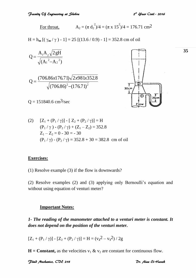
Example 3:
A 30 cm x 15 cm venturi meter is provided to vertical pipe line carrying oil
with 0.9 specific gravity. The flow direction is upwards. The difference in
elevation between inlet and throat is 30 cm. The reading of a mercury
manometer is 25 cm.
1- Calculate the discharge?
2- Determine the pressure head between inlet and throat?
Solution
(1) For inlet, A1 = (π d1
2)/4 = (π x 30
2)/4 = 706.86 cm2
)A(A
gH2AAQ
22
21
21
22 )54.78()7.176(
2.2829812)54.787.176(Q
xxx
Faculty Of Engineering at Shobra 2nd Year Civil - 2016
Fluid Mechanics, CVE 214 Dr. Alaa El-Hazek
35
For throat, A2 = (π d2
2)/4 = (π x 15
2)/4 = 176.71 cm2
H = hm [( m / ) - 1] = 25 [(13.6 / 0.9) - 1] = 352.8 cm of oil
Q = 151840.6 cm3/sec
(2) [Z1 + (P1 / )] - [ Z2 + (P2 / )] = H
(P1 / ) - (P2 / ) + (Z1 – Z2) = 352.8
Z1 – Z2 = 0 - 30 = - 30
(P1 / ) - (P2 / ) = 352.8 + 30 = 382.8 cm of oil
Exercises:
(1) Resolve example (3) if the flow is downwards?
(2) Resolve examples (2) and (3) applying only Bernoulli’s equation and
without using equation of venturi meter?
Important Notes:
1- The reading of the manometer attached to a venturi meter is constant. It
does not depend on the position of the venturi meter.
[Z1 + (P1 / )] - [Z2 + (P2 / )] = H = (v22 – v1
2) / 2g
H = Constant, as the velocities v1 & v2 are constant for continuous flow.
)A(A
gH2AAQ
22
21
21
22 )71.176()86.706(
8.3529812)71.17686.706(Q
xxx
Faculty Of Engineering at Shobra 2nd Year Civil - 2016
Fluid Mechanics, CVE 214 Dr. Alaa El-Hazek
36
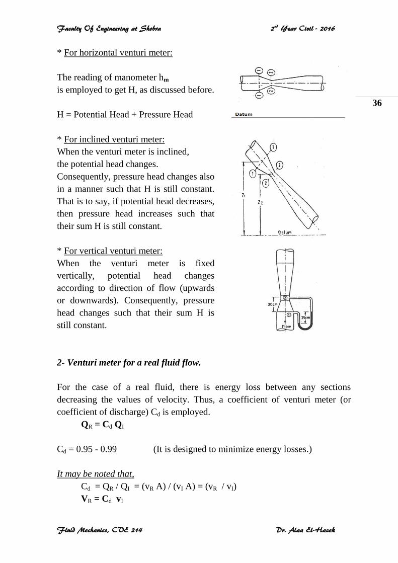
* For horizontal venturi meter:
The reading of manometer hm
is employed to get H, as discussed before.
H = Potential Head + Pressure Head
* For inclined venturi meter:
When the venturi meter is inclined,
the potential head changes.
Consequently, pressure head changes also
in a manner such that H is still constant.
That is to say, if potential head decreases,
then pressure head increases such that
their sum H is still constant.
* For vertical venturi meter:
When the venturi meter is fixed
vertically, potential head changes
according to direction of flow (upwards
or downwards). Consequently, pressure
head changes such that their sum H is
still constant.
2- Venturi meter for a real fluid flow.
For the case of a real fluid, there is energy loss between any sections
decreasing the values of velocity. Thus, a coefficient of venturi meter (or
coefficient of discharge) Cd is employed.
QR = Cd QI
Cd = 0.95 - 0.99 (It is designed to minimize energy losses.)
It may be noted that,
Cd = QR / QI = (vR A) / (vI A) = (vR / vI)
VR = Cd vI
Faculty Of Engineering at Shobra 2nd Year Civil - 2016
Fluid Mechanics, CVE 214 Dr. Alaa El-Hazek
37
3- Negative pressure at the throat of a venturi meter.
At the throat of a venturi meter, the velocity is maximum because it has
minimum cross sectional area and consequently the pressure is minimum.
Thus, the pressure may be zero or even negative. When this negative pressure
reaches the value of vapor pressure of the liquid flowing in the pipe, the liquid
evaporates. So, the flow becomes discontinuous due to the existed vapor.
Cavitation takes place as the liquid evaporates and the vapor condenses to a
liquid and so on.
To avoid cavitation, the pressure at the throat of a venturi meter has not to
reach the value of vapor pressure of the flowing liquid.
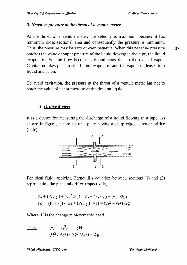
II- Orifice Meter:
It is a device for measuring the discharge of a liquid flowing in a pipe. As
shown in figure, it consists of a plate having a sharp edged circular orifice
(hole).
For ideal fluid, applying Bernoulli’s equation between sections (1) and (2)
representing the pipe and orifice respectively,
Z1 + (P1 / ) + (v12 /2g) = Z2 + (P2 / ) + (v2
2 /2g)
[Z1 + (P1 / )] - [Z2 + (P2 / )] = H = (v22 – v1
2) /2g
Where, H is the change in piezometric head.
Then, (v22 - v1
2) = 2 g H
(Q2 / A22) - (Q2 /A1
2) = 2 g H
Faculty Of Engineering at Shobra 2nd Year Civil - 2016
Fluid Mechanics, CVE 214 Dr. Alaa El-Hazek
38
Q2 [(1/A22) - (1/A1
2)] = 2 g H
Q2 = [(A12 A2
2) / (A12 - A2
2)] (2 g H)
This is the equation of orifice for measuring discharge of ideal fluid flowing
in a pipe.
For the case of a real fluid, there is energy loss between any sections
decreasing the values of velocity. Thus, a coefficient of discharge Cd is
employed, that accounts for both velocity and contraction.
QR = Cd QI
Cd = 0.6 (It is simple and cheap with high energy losses.)
In fact, there is a vena contraction downstream the orifice at a distance = (1/2)
diameter of orifice, say at section (3).
Introducing the effect of this contraction, the equation (1) is applied for
sections (1) and (3) obtaining another equation of orifice.
Example 4:
An orifice meter has an orifice of 10 cm diameter and a coefficient of
discharge of 0.65. It is fixed in a pipe of 25 cm diameter with flowing oil of
0.8 specific gravity. The pressure difference between pipe and orifice is
measured by a mercury manometer that gives a reading of 80 cm.
Determine the discharge?
Solution
For pipe, A1 = (π d1
2)/4 = (π x 25
2)/4 = 490.87 cm2
For orifice, A2 = (π d2
2)/4 = (π x 10
2)/4 = 78.54 cm2
)A(A
gH2AAQ
22
21
21
Faculty Of Engineering at Shobra 2nd Year Civil - 2016
Fluid Mechanics, CVE 214 Dr. Alaa El-Hazek
39
H = hm [( m / ) - 1] = 80 [(13.6 / 0.8) - 1] = 1280 cm of oil
x 0.65
Q = 81957.8 cm3/sec
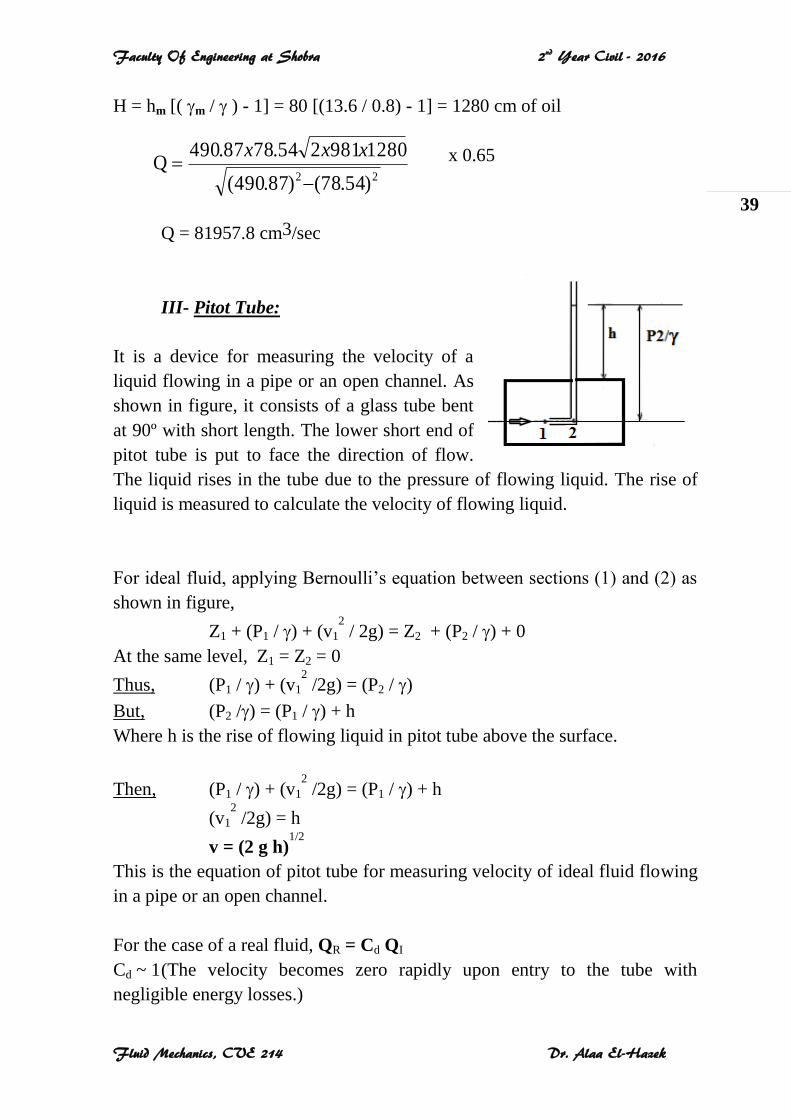
III- Pitot Tube:
It is a device for measuring the velocity of a
liquid flowing in a pipe or an open channel. As
shown in figure, it consists of a glass tube bent
at 90º with short length. The lower short end of
pitot tube is put to face the direction of flow.
The liquid rises in the tube due to the pressure of flowing liquid. The rise of
liquid is measured to calculate the velocity of flowing liquid.
For ideal fluid, applying Bernoulli’s equation between sections (1) and (2) as
shown in figure,
Z1 + (P1 / ) + (v1
2 / 2g) = Z2 + (P2 / ) + 0
At the same level, Z1 = Z2 = 0
Thus, (P1 / ) + (v1
2 /2g) = (P2 / )
But, (P2 /) = (P1 / ) + h
Where h is the rise of flowing liquid in pitot tube above the surface.
Then, (P1 / ) + (v1
2 /2g) = (P1 / ) + h
(v1
2 /2g) = h
v = (2 g h)1/2
This is the equation of pitot tube for measuring velocity of ideal fluid flowing
in a pipe or an open channel.
For the case of a real fluid, QR = Cd QI
Cd ~ 1 (The velocity becomes zero rapidly upon entry to the tube with
negligible energy losses.)
22 )54.78()87.490(
1280981254.7887.490Q
xxx
Faculty Of Engineering at Shobra 2nd Year Civil - 2016
Fluid Mechanics, CVE 214 Dr. Alaa El-Hazek
40
Chapter 5
FLOW THROUGH AN ORIFICE
5-1 The Orifice 5-2 Orifice under a Constant Head
5-3 Orifice under a Varying Head
5-1 The Orifice:
It is a small opening in any vessel through which liquid flows out. An orifice
may be located in a vertical side of the vessel or in its base. It may be rounded
or sharp edged. The main function of an orifice is measuring the discharge.
5-2 Orifice under a Constant Head:
Jet of Liquid:
It is the continuous stream of liquid that flows out the orifice.
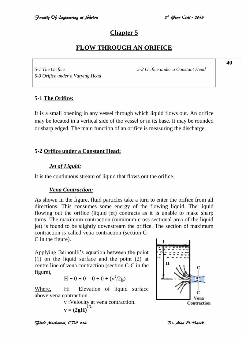
Vena Contraction:
As shown in the figure, fluid particles take a turn to enter the orifice from all
directions. This consumes some energy of the flowing liquid. The liquid
flowing out the orifice (liquid jet) contracts as it is unable to make sharp
turns. The maximum contraction (minimum cross sectional area of the liquid
jet) is found to be slightly downstream the orifice. The section of maximum
contraction is called vena contraction (section C-
C in the figure).
Applying Bernoulli’s equation between the point
(1) on the liquid surface and the point (2) at
centre line of vena contraction (section C-C in the
figure),
H + 0 + 0 = 0 + 0 + (v2/2g)
Where, H: Elevation of liquid surface
above vena contraction.
v :Velocity at vena contraction.
v = (2gH)1/2
Faculty Of Engineering at Shobra 2nd Year Civil - 2016
Fluid Mechanics, CVE 214 Dr. Alaa El-Hazek
41
Coefficient of Contraction Cc:
Cc = Actual Area = Area of Jet at Vena Contraction = Ac
Theoretical Area Area of Orifice Ao
Ac = Cc Ao & Cc = 0.61 - 0.69
Coefficient of Velocity Cv:
Considering the friction loss of energy between the two points, thus:
Cv = Actual Velocity = va
Theoretical Velocity v
va = Cv v & Cv = 0.95 - 0.99
Coefficient of Discharge Cd:
Cd = Actual Discharge = Qa
Theoretical Discharge Q
Qa = Cd Q
Q = Ao v
Qa = Ac va = (Cc Ao) (Cv v) = (Cc Cv) (Ao v)
Thus, Cd = Cc Cv
Example 1:
Water of head 9 m is flowing through an orifice of 60 mm diameter. The
coefficients of discharge and velocity are 0.6 and 0.9 respectively.
1- Calculate the actual discharge through the orifice?
2- Determine the actual velocity at vena contraction?
Solution
1- Ao = π d2 / 4 = (π 6
2) / 4 = 28.27 cm
2
Q = Ao (2gH)1/2
= 28.27 [2 (981) (900)] 1/2
= 37566.14 cm3/sec
Faculty Of Engineering at Shobra 2nd Year Civil - 2016
Fluid Mechanics, CVE 214 Dr. Alaa El-Hazek
42
Qa = Cd Q = 0.6 (37566.14) = 22539.68 cm3/sec
2- v = (2gH)1/2
= [2 (981) (900)]1/2
= 1328.83 cm/sec
va = Cv v = 0.9 (1328.83) = 1195.95 cm/sec
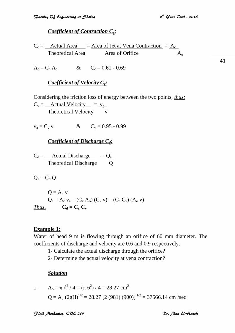
5-3 Orifice under a Varying Head:
Assume a tank, as shown in the figure, of a cross sectional area AT contains a
liquid that is flowing through an orifice. During a period of time T, the liquid
level decreased from H1 to H2.
At some instant, the liquid height is (h+dh) above
the orifice. During a small interval of time dt, the
head decreases by a small amount dh.
The actual discharge of liquid flowing out the
orifice is dQ, dQ = Cd Ao (2 g h)1/2
The volume of liquid flowing out the orifice is dV,
dV = dQ dt = Cd Ao (2 g h)1/2 dt
Also, with respect to the tank, the liquid volume in it decreased during the
time interval dt by the amount dV, dV = - AT dh
Thus, Cd Ao (2 g h)1/2 dt = - AT dh
dt = - AT (h)-1/2 dh / Cd Ao (2 g)1/2
The total time T for decreasing liquid level from H1 to H2,
T = [- AT / Cd Ao (2 g)1/2] (h)-1/2 dh
T = - 2 AT (H21/2 - H11/2) / Cd Ao (2 g)1/2
Minus sign may be eliminated by using (H1 - H2), where H1 > H2.
T = 2 AT (H11/2 - H21/2) / Cd Ao (2 g)1/2 gAC
HHAT
od
T
2
)21(2
Faculty Of Engineering at Shobra 2nd Year Civil - 2016
Fluid Mechanics, CVE 214 Dr. Alaa El-Hazek
43
Applications:
This equation can be used to determine the time T required to reduce the
liquid surface from one level to another.
Also, it can be applied to detect the time T required to empty any tank
containing a liquid. For this case, the liquid level decreases from H1 to zero.
Example 2:
A swimming pool 10 m long and 6 m wide holds water to a depth of 1.25 m.
The water is discharged from the pool through an orifice at its bottom. The
area of the orifice is 0.23 m2, and the coefficient of discharge is 0.62.
Determine the time required to completely empty the pool?
Solution
AT = 10 x 6 = 60 m2
Ao = 0.23 m2
H1 = 1.25 m & H2 = 0
T = 212 sec
gAC
HHAT
od
T
2
)21(2
81.9*223.0*62.0
)025.1(60*2 T
Faculty Of Engineering at Shobra 2nd Year Civil - 2016
Fluid Mechanics, CVE 214 Dr. Alaa El-Hazek
44
Chapter 6
MOMENTUM EQUATION
6-1 Momentum 6-2 Force Applied by a Liquid Jet on a Flat Plate
6-1 Momentum:
Momentum of any moving body (such as a flowing fluid particle) is the
quantity of motion. It is the product of its mass and velocity.
Momentum = Mass x Velocity = M * v
Units: SI system: kg.m/s
Examples:
The lift force on an aircraft is exerted by the air moving over the wing.
A jet of water from a hose exerts a force on whatever it hits.
As the velocity, the momentum is a vector quantity.
According to Newton's second law, the rate of change of momentum of a
moving body (or its acceleration) is equal to the resultant force acting on the
body, and takes place in the direction of the force.
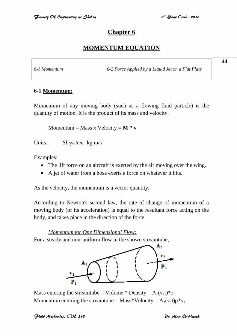
Momentum for One Dimensional Flow:
For a steady and non-uniform flow in the shown streamtube,
Mass entering the streamtube = Volume * Density = A1(v1t)*
Momentum entering the streamtube = Mass*Velocity = A1(v1t)*v1
Faculty Of Engineering at Shobra 2nd Year Civil - 2016
Fluid Mechanics, CVE 214 Dr. Alaa El-Hazek
45
Similarly,
Mass leaving the streamtube = Volume * Density = A2(v2t)*
Momentum leaving the streamtube = Mass*Velocity = A2(v2t)*v2
Resultant force on the fluid = Rate of change of momentum
F = [A2(v2t)*v2 – A1(v1t)*v1] / t & Q = A2 v2 = A1 v1
F = Q (v2 – v1)
The resultant force is acting in the direction of the flow of the fluid.
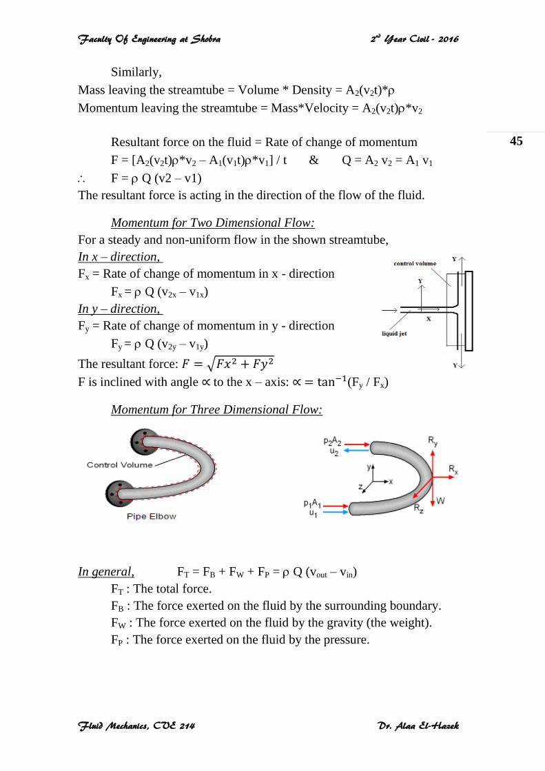
Momentum for Two Dimensional Flow:
For a steady and non-uniform flow in the shown streamtube,
In x – direction,
Fx = Rate of change of momentum in x - direction
Fx = Q (v2x – v1x)
In y – direction,
Fy = Rate of change of momentum in y - direction
Fy = Q (v2y – v1y)
The resultant force:
F is inclined with angle to the x – axis: (Fy / Fx)
Momentum for Three Dimensional Flow:
In general, FT = FB + FW + FP = Q (vout – vin)
FT : The total force.
FB : The force exerted on the fluid by the surrounding boundary.
FW : The force exerted on the fluid by the gravity (the weight).
FP : The force exerted on the fluid by the pressure.
Faculty Of Engineering at Shobra 2nd Year Civil - 2016
Fluid Mechanics, CVE 214 Dr. Alaa El-Hazek
46
According to Newton’s third law, the fluid will exert an equal and opposite
reaction.
The reaction or the force exerted by the fluid on the surrounding boundary is
equal and opposite to (FB).
R = – FB
6-2 Force Applied by a Liquid Jet on a Flat Plate:
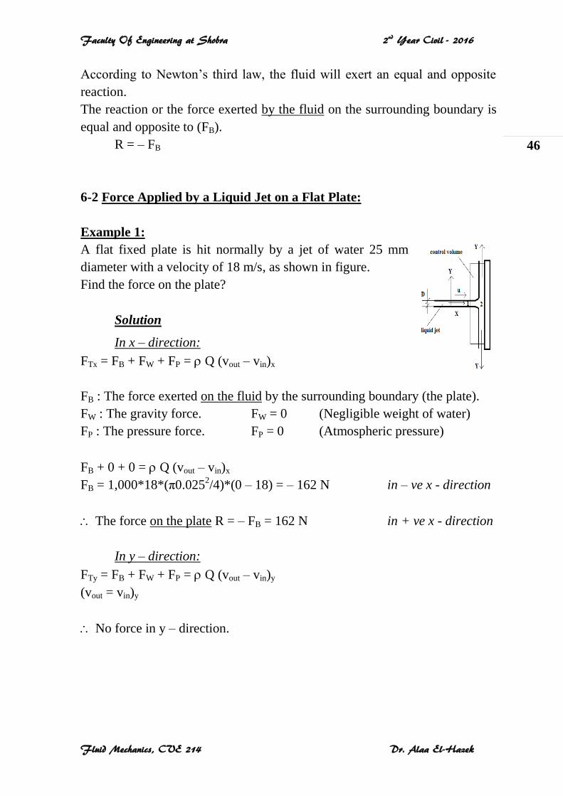
Example 1:
A flat fixed plate is hit normally by a jet of water 25 mm
diameter with a velocity of 18 m/s, as shown in figure.
Find the force on the plate?
Solution
In x – direction:
FTx = FB + FW + FP = Q (vout – vin)x
FB : The force exerted on the fluid by the surrounding boundary (the plate).
FW : The gravity force. FW = 0 (Negligible weight of water)
FP : The pressure force. FP = 0 (Atmospheric pressure)
FB + 0 + 0 = Q (vout – vin)x
FB = 1,000*18*(π0.0252/4)*(0 – 18) = – 162 N in – ve x - direction
The force on the plate R = – FB = 162 N in + ve x - direction
In y – direction:
FTy = FB + FW + FP = Q (vout – vin)y
(vout = vin)y
No force in y – direction.
Faculty Of Engineering at Shobra 2nd Year Civil - 2016
Fluid Mechanics, CVE 214 Dr. Alaa El-Hazek
47
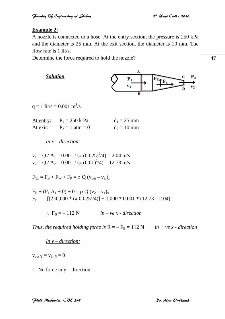
Example 2:
A nozzle is connected to a hose. At the entry section, the pressure is 250 kPa
and the diameter is 25 mm. At the exit section, the diameter is 10 mm. The
flow rate is 1 lit/s.
Determine the force required to hold the nozzle?
Solution
q = 1 lit/s = 0.001 m3/s
At entry: P1 = 250 k Pa d1 = 25 mm
At exit: P2 = 1 atm = 0 d2 = 10 mm
In x – direction:
v1 = Q / A1 = 0.001 / (π (0.025)2/4) = 2.04 m/s
v2 = Q / A2 = 0.001 / (π (0.01)2/4) = 12.73 m/s
FTx = FB + FW + FP = Q (vout – vin)x
FB + (P1 A1 + 0) + 0 = Q (v2 – v1)x
FB = – [(250,000 * (π 0.0252/4)] + 1,000 * 0.001 * (12.73 – 2.04)
FB = – 112 N in – ve x - direction
Thus, the required holding force is R = – FB = 112 N in + ve x - direction
In y – direction:
vout Y = vin Y = 0
No force in y – direction.