Chapter 4 Drawing Basics
41
Chapter 4. Drawing Basics As handy as forms are, especially when laden with controls, sometimes the built-in controls [1] aren't sufficient to render the state of your application. In that case, you need to draw the state yourself. The drawing may be to the screen, to a file, or to a printer, but wherever you're drawing to, you'll be dealing with the same primitives—colors, brushes, pens, and fonts—and the same kinds of things to draw: shapes, images, and strings. This chapter starts by examining the basics of drawing to the screen and the building blocks of drawing. [1] The standard controls that come with WinForms are listed in Appendix D: Standard WinForms Components and Controls. Note that all the drawing techniques discussed in this chapter and in the next two chapters relate equally as well to controls as they do to forms. For information about building custom controls, see Chapter 8: Controls. One more thing worth noting be fore we begin is that the System.Drawing namespace is implemented on top of GDI+ (Graphics Device Interface+), the successor to GDI. The original GDI has been a mainstay in Windows since there was a Windows, providing an abstraction over screens and printers to make writing GUI-style applications easy . [2] GDI+ is a Win32 DLL (gdiplus.dll) that ships with Windows XP and is available for older versions of Windows. GDI+ is also an unmanaged C++ class library that wraps gdiplus.dll. Because the System.Drawing classes share many of the same names with the GDI+ C++ classes, you may very well stumble onto the unmanaged classes when looking for the .NET classes in the online documentation. The concepts are the same, but the coding details are very different between unmanaged C++ and managed anything else, so keep an eye out. [2] GDI programming certainly isn't easy when compared with System.Drawing programming, but it's orders of magnitude easier than supporting printers and video display adapters by hand, which was what DOS programmers had to do to put bread on the table. Drawing to the Screen No matter what kind of drawing you're doing, the underlying abstraction that you're dealing with is the Graphics class from the System.Drawing namespace. The Graphics class provides the abstract surface on which you're drawing, whether the results of your drawing operations are displayed on the screen, stored in a file, or spooled to the printer. The Graphics class is too large to show here, but we'll come back to it again and again throughout the chapter.
Transcript of Chapter 4 Drawing Basics

8/6/2019 Chapter 4 Drawing Basics
http://slidepdf.com/reader/full/chapter-4-drawing-basics 1/41
Chapter 4. Drawing Basics
As handy as forms are, especially when laden with controls, sometimes the built-in
controls[1] aren't sufficient to render the state of your application. In that case, you need to
draw the state yourself. The drawing may be to the screen, to a file, or to a printer, but
wherever you're drawing to, you'll be dealing with the same primitives—colors, brushes,
pens, and fonts—and the same kinds of things to draw: shapes, images, and strings. This
chapter starts by examining the basics of drawing to the screen and the building blocks of
drawing.
[1] The standard controls that come with WinForms are listed in Appendix D: Standard WinForms Components and Controls.
Note that all the drawing techniques discussed in this chapter and in the next two chapters
relate equally as well to controls as they do to forms. For information about building
custom controls, see Chapter 8: Controls.
One more thing worth noting before we begin is that the System.Drawing namespace is
implemented on top of GDI+ (Graphics Device Interface+), the successor to GDI. The
original GDI has been a mainstay in Windows since there was a Windows, providing an
abstraction over screens and printers to make writing GUI-style applications easy.[2] GDI+
is a Win32 DLL (gdiplus.dll) that ships with Windows XP and is available for older
versions of Windows. GDI+ is also an unmanaged C++ class library that wraps
gdiplus.dll. Because the System.Drawing classes share many of the same names with the
GDI+ C++ classes, you may very well stumble onto the unmanaged classes when lookingfor the .NET classes in the online documentation. The concepts are the same, but the
coding details are very different between unmanaged C++ and managed anything else, so
keep an eye out.
[2] GDI programming certainly isn't easy when compared with System.Drawing programming, but it's orders of magnitude easier than
supporting printers and video display adapters by hand, which was what DOS programmers had to do to put bread on the table.
Drawing to the Screen
No matter what kind of drawing you're doing, the underlying abstraction that you'redealing with is the Graphics class from the System.Drawing namespace. The Graphics
class provides the abstract surface on which you're drawing, whether the results of your
drawing operations are displayed on the screen, stored in a file, or spooled to the printer.
The Graphics class is too large to show here, but we'll come back to it again and again
throughout the chapter.

8/6/2019 Chapter 4 Drawing Basics
http://slidepdf.com/reader/full/chapter-4-drawing-basics 2/41
One way to obtain a graphics object is to use CreateGraphics to create a new one
associated with a form:
bool drawEllipse = false;
void drawEllipseButton_Click(object sender, EventArgs e) {// Toggle whether or not to draw the ellipsedrawEllipse = !drawEllipse;
Graphics g = this.CreateGraphics(); try {
if( drawEllipse ) {// Draw the ellipseg.FillEllipse(Brushes.DarkBlue, this.ClientRectangle);
}else {// Erase the previously drawn ellipseg.FillEllipse(SystemBrushes.Control, this.ClientRectangle);
} } finally { g.Dispose(); }}
After we have a graphics object, we can use it to draw on the form. Because we're using
the button to toggle whether or not to draw the ellipse, we either draw an ellipse in dark
blue or use the system color as the background of the form. All that's fine, but you may
wonder what the try-catch block is for.
Because the graphics object holds an underlying resource managed by Windows, we'reresponsible for releasing the resource when we're finished, even in the face of an
exception, and that is what the try-finally block is for. The Graphics class, like many
classes in .NET, implements the IDisposable interface. When an object implements the
IDisposable interface, that's a signal for the client of that object to call the IDisposable
Dispose method when the client is finished with the object. This lets the object know that
it's time to clean up any resources it's holding, such as a file or a database connection. In
this case, the Graphic class's implementation of IDisposable Dispose can release the
underlying graphics object that it's maintaining.
To simplify things in C#, the try-catch block can be replaced with a using block:
void drawEllipseButton_Click(object sender, EventArgs e) { using( Graphics g = this.CreateGraphics() ) {
g.FillEllipse(Brushes.DarkBlue, this.ClientRectangle); } // g.Dispose called automatically here
}

8/6/2019 Chapter 4 Drawing Basics
http://slidepdf.com/reader/full/chapter-4-drawing-basics 3/41
The C# using block wraps the code it contains in a try block and always calls the
IDisposable Dispose method at the end of the block for objects created as part of the
using clause. This is a convenient shortcut for C# programmers. It's a good practice to get
into and something you'll see used extensively in the rest of this book.
Handling the Paint Event
After we've got the Graphics resources managed properly, we have another issue: When
the form is resized or covered and uncovered, the ellipse is not automatically redrawn. To
deal with this, Windows asks a form (and all child controls) to redraw newly uncovered
content via the Paint event, which provides a PaintEventArgs argument:
class PaintEventArgs {public Rectangle ClipRectangle { get; }public Graphics Graphics { get; }
}
bool drawEllipse = false;
void drawEllipseButton_Click(object sender, EventArgs e) {drawEllipse = !drawEllipse;
}
void DrawingForm_Paint(object sender, PaintEventArgs e) {
if( !drawEllipse ) return; Graphics g = e.Graphics;g.FillEllipse(Brushes.DarkBlue, this.ClientRectangle);
}
By the time the Paint event is fired, the background of the form has already been drawn,[3]
so any ellipse that was drawn during the last Paint event will be gone; this means that we
must draw the ellipse only if the flag is set to true. However, even if we set the flag to
draw the ellipse, Windows doesn't know that the state of the flag has changed, so the
Paint event won't be triggered and the form won't get a chance to draw the ellipse. To
avoid the need to draw the ellipse in the button's Click event as well as the form's Paint
event, we must request a Paint event and let Windows know that the form needs to be
redrawn.
[3] A form or control can draw its own background by overriding the OnPaintBackground method.
Triggering the Paint Event
To request a Paint event, we use the Invalidate method:
void drawEllipseButton_Click(object sender, EventArgs e) {

8/6/2019 Chapter 4 Drawing Basics
http://slidepdf.com/reader/full/chapter-4-drawing-basics 4/41
drawEllipse = !drawEllipse;
this.Invalidate(true); // Ask Windows for a Paint event // for the form and its children
}
Now, when the user toggles the flag, we call Invalidate to let Windows know that a partof the form needs to be redrawn. However, because drawing is one of the more expensive
operations, Windows will first handle all other events—such as mouse movements,
keyboard entry, and so on—before firing the Paint event, just in case multiple areas of the
form need to be redrawn at the same time.
To avoid this delay, use the Update method, which forces Windows to handle the Paint
event immediately. Because invalidating and updating the entire client area of a form are
so common, forms also have a Refresh method that combines the two:
void drawEllipseButton_Click(object sender, EventArgs e) {drawEllipse = !drawEllipse;
// Can do one or the other this.Invalidate(true); // Ask Windows for a Paint event // for the form and its children this.Update(); // Force the Paint event to happen now
// Or can do both at once this.Refresh(); // Invalidate(true) + Update
}
However, if you can wait, it's best to let Windows handle the Paint event in its own sweet
time. It's delayed for a reason: It's the slowest thing that the system does. Forcing all
paints to happen immediately eliminates an important optimization.
If you've been following along with this simple example, you'll be pleased to see that
pressing the button toggles whether or not the ellipse is shown on the form and that
covering and uncovering the form draws as expected. However, if you resize the form,
you'll be disappointed, as shown in Figures 4.1 and 4.2.
Figure 4.1. Ellipse Form before Resizing
8/6/2019 Chapter 4 Drawing Basics
http://slidepdf.com/reader/full/chapter-4-drawing-basics 5/41
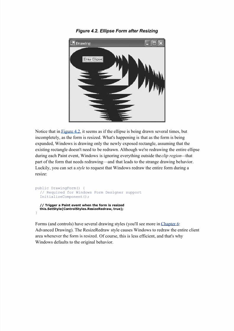
Figure 4.2. Ellipse Form after Resizing
Notice that in Figure 4.2, it seems as if the ellipse is being drawn several times, but
incompletely, as the form is resized. What's happening is that as the form is being
expanded, Windows is drawing only the newly exposed rectangle, assuming that the
existing rectangle doesn't need to be redrawn. Although we're redrawing the entire ellipse
during each Paint event, Windows is ignoring everything outside the clip region— that
part of the form that needs redrawing—and that leads to the strange drawing behavior.
Luckily, you can set a style to request that Windows redraw the entire form during a
resize:
public DrawingForm() {// Required for Windows Form Designer supportInitializeComponent();
// Trigger a Paint event when the form is resized this.SetStyle(ControlStyles.ResizeRedraw, true);
}
Forms (and controls) have several drawing styles (you'll see more in Chapter 6:
Advanced Drawing). The ResizeRedraw style causes Windows to redraw the entire clientarea whenever the form is resized. Of course, this is less efficient, and that's why
Windows defaults to the original behavior.

8/6/2019 Chapter 4 Drawing Basics
http://slidepdf.com/reader/full/chapter-4-drawing-basics 6/41
Colors
So far, I've been drawing the ellipse in my form using a built-in dark blue brush. A brush,
as you'll see, is for filling the interior of a shape, whereas a pen is used to draw the edge
of a shape. Either way, suppose I'm not quite happy with the dark blue brush. Instead, I'dlike a brush of one of the more than 16 million colors that doesn't come prebuilt for me,
and this means that I first need to specify the color in which I'm interested. Color is
modeled in .NET via the Color structure:
struct Color {// No colorpublic static readonly Color Empty;
// Built-in colorspublic static Color AliceBlue { get; }
// ...public static Color YellowGreen { get; }
// Propertiespublic byte A { get; }public byte B { get; }public byte G { get; }public bool IsEmpty { get; }public bool IsKnownColor { get; }public bool IsNamedColor { get; }public bool IsSystemColor { get; }public string Name { get; }public byte R { get; }
// Methodspublic static Color FromArgb(int alpha, Color baseColor);public static Color FromArgb(int alpha, int red, int green, int blue);public static Color FromArgb(int argb);public static Color FromArgb(int red, int green, int blue);public static Color FromKnownColor(KnownColor color);public static Color FromName(string name);public float GetBrightness();public float GetHue();public float GetSaturation();public int ToArgb();public KnownColor ToKnownColor();
}
Fundamentally, a Color object represents four values: the amount of red, green, and blue
color and the amount of opacity. The red, green, and blue elements are often referred to
together as RGB (red-green-blue), and each ranges from 0 to 255, with 0 being the
smallest amount of color and 255 being the greatest amount of color. The degree of
opacity is specified by an alpha value, which is sometimes seen together with RGB as

8/6/2019 Chapter 4 Drawing Basics
http://slidepdf.com/reader/full/chapter-4-drawing-basics 7/41
ARBG (Alpha-RBG). The alpha value ranges from 0 to 255, where 0 is completely
transparent and 255 is completely opaque.
Instead of using a constructor, you create a Color object by using the FromArbg method,
passing brightness settings of red, green, and blue:
Color red = Color.FromArgb(255, 0, 0); // 255 red, 0 blue, 0 greenColor green = Color.FromArgb(0, 255, 0); // 0 red, 255 blue, 0 greenColor blue = Color.FromArgb(0, 0, 255); // 0 red, 0 blue, 255 greenColor white = Color.FromArgb(255, 255, 255); // whiteColor black = Color.FromArgb(0, 0, 0); // black
If you'd like to specify the degree of transparency as well, you pass an alpha value:
Color blue25PercentOpaque = Color.FromArgb(255*1/4, 0, 0, 255);
Color blue75PercentOpaque = Color.FromArgb(255*3/4, 0, 0, 255);
The three 8-bit color values and the 8-bit alpha value make up the four parts of a single
value that defines the 32-bit color that modern video display adaptors can handle. If you
prefer to pass the four values combined into the single 32-bit value, you can do that with
another of the overloads, although it's fairly awkward and therefore usually avoided:
// A = 191, R = 0, G = 0, B = 255Color blue75PercentOpache = Color.FromArgb(-1090518785);
Known Colors
Often, the color you're interested in already has a well-known name, and this means that
it will already be available from the static fields of Color that define known colors, from
the KnownColor enumeration, and by name:
Color blue1 = Color.BlueViolet;Color blue2 = Color.FromKnownColor(KnownColor.BlueViolet);Color blue3 = Color.FromName("BlueViolet");
In addition to 141 colors with names such as AliceBlue and OldLace, the KnownColor enumeration has 26 values describing the current colors assigned to various parts of the
Windows UI, such as the color of the border on the active window and the color of the
default background of a control. These colors are handy when you're doing custom
drawing and you'd like to match the rest of the system. The system color values of the
KnownColor enumeration are shown here:

8/6/2019 Chapter 4 Drawing Basics
http://slidepdf.com/reader/full/chapter-4-drawing-basics 8/41
enum KnownColor {// Nonsystem colors elided...ActiveBorder,ActiveCaption,ActiveCaptionText,AppWorkspace,Control,ControlDark,ControlDarkDark,ControlLight,ControlLightLight,ControlText,Desktop,GrayTextHighlight,HighlightText,HotTrack,InactiveBorder,InactiveCaption,
InactiveCaptionText,Info,InfoText,Menu,MenuText,ScrollBar,Window,WindowFrame,WindowText,
}
If you'd like to use one of the system colors without creating your own instance of the
Color class, you can access them already created for you and exposed as properties of theSystemColors class:
sealed class SystemColors {// Propertiespublic static Color ActiveBorder { get; }public static Color ActiveCaption { get; }public static Color ActiveCaptionText { get; }public static Color AppWorkspace { get; }public static Color Control { get; }public static Color ControlDark { get; }public static Color ControlDarkDark { get; }
public static Color ControlLight { get; }public static Color ControlLightLight { get; }public static Color ControlText { get; }public static Color Desktop { get; }public static Color GrayText { get; }public static Color Highlight { get; }public static Color HighlightText { get; }public static Color HotTrack { get; }public static Color InactiveBorder { get; }public static Color InactiveCaption { get; }

8/6/2019 Chapter 4 Drawing Basics
http://slidepdf.com/reader/full/chapter-4-drawing-basics 9/41
public static Color InactiveCaptionText { get; }public static Color Info { get; }public static Color InfoText { get; }public static Color Menu { get; }public static Color MenuText { get; }public static Color ScrollBar { get; }public static Color Window { get; }public static Color WindowFrame { get; }public static Color WindowText { get; }
}
The following two lines yield Color objects with the same color values, and you can use
whichever one you like:
Color color1 = Color.FromKnownColor(KnownColor.GrayText);Color color2 = SystemColors.GrayText;
Color Translation
If you have a color in one of three other formats—HTML, OLE, or Win32—or you'd like
to translate to one of these formats, you can use ColorTranslator, as shown here for
HTML:
Color htmlBlue = ColorTranslator.FromHtml("#0000ff");string htmlBlueToo = ColorTranslator.ToHtml(htmlBlue);
When you have a Color, you can get its alpha, red, blue, and green values as well as the
color's name, whether it's a known color or a system color. You can also use these valuesto fill and frame shapes, which require brushes and pens, respectively.
Print E-Mail Add Note Add Bookmark
Windows Forms Programming in C#
By Chris Sells
Slots : 1
Table of Contents
Chapter 4. Drawing Basics

8/6/2019 Chapter 4 Drawing Basics
http://slidepdf.com/reader/full/chapter-4-drawing-basics 10/41
Brushes
The System.Drawing.Brush class serves as a base class for several kinds of brushes,
depending on your needs. Figure 4.3 shows the five derived brush classes provided in the
System.Drawing and System.Drawing.Drawing2D namespaces.
Figure 4.3. Sample Brushes
Figure 4.3 was created with the following code:
void BrushesForm_Paint(object sender, PaintEventArgs e) {Graphics g = e.Graphics;int x = 0;int y = 0;int width = this.ClientRectangle.Width;int height = this.ClientRectangle.Height/5;Brush whiteBrush = System.Drawing.Brushes.White;Brush blackBrush = System.Drawing.Brushes.Black;
using( Brush brush = new SolidBrush(Color.DarkBlue) ) {g.FillRectangle(brush, x, y, width, height);
g.DrawString(brush.ToString(), this.Font, whiteBrush, x, y);y += height;
}
string file = @"c:\windows\Santa Fe Stucco.bmp";using( Brush brush =
new TextureBrush(new Bitmap(file)) ) {
g.FillRectangle(brush, x, y, width, height);g.DrawString(brush.ToString(), this.Font, whiteBrush, x, y);y += height;

8/6/2019 Chapter 4 Drawing Basics
http://slidepdf.com/reader/full/chapter-4-drawing-basics 11/41
Pens
Whereas the Brush classes are used to fill shapes, the Pen class is used to frame shapes.
The interesting members are shown here:
sealed class Pen : MarshalByRefObject, ICloneable, IDisposable {// Constructorspublic Pen(Brush brush);public Pen(Brush brush, float width);
public Pen(Color color);public Pen(Color color, float width);
// Propertiespublic PenAlignment Alignment { get; set; }
public Brush Brush { get; set; }public Color Color { get; set; }public float[] CompoundArray { get; set; }public CustomLineCap CustomEndCap { get; set; }public CustomLineCap CustomStartCap { get; set; }public DashCap DashCap { get; set; }public float DashOffset { get; set; }public float[] DashPattern { get; set; }public DashStyle DashStyle { get; set; }public LineCap EndCap { get; set; }public LineJoin LineJoin { get; set; }public float MiterLimit { get; set; }public PenType PenType { get; }
public LineCap StartCap { get; set; }public float Width { get; set; }
// Transformation members elided...
// Methodspublic void SetLineCap(...);
}
Pens have several interesting properties, including a width, a color or a brush, start and
end cap styles, and a dash pattern for the line itself. One note of interest is that the width
of a pen is specified in the units of the underlying Graphics being drawn on (more
information about Graphics units is available in Chapter 6: Advanced Drawing).However, no matter what the underlying units, a pen width of 0 always translates into a
width of 1 physical unit on the underlying Graphic surface. This lets you specify the
smallest visible pen width without worrying about the units of a particular surface.

8/6/2019 Chapter 4 Drawing Basics
http://slidepdf.com/reader/full/chapter-4-drawing-basics 12/41
You'll notice that the Pen class is sealed. This means that it can't be used as a base class
for further penlike functionality. Instead, each pen has a type that governs its behavior, as
determined by the PenType enumeration:
enum PenType {SolidColor, // Created from a color or a SolidBrushTextureFill, // Created from a TextureBrushHatchFill, // Created from a HatchBrushLinearGradient, // Created from a LinearGradientBrushPathGradient, // Created from a PathGradientBrush
}
If you're interested in common, solid-color pens, the 141 named pens are provided as
static Pen properties on the Pens class, and 15 system pens are provided as static Pen
properties on the SystemPens class, providing the same usage as the corresponding
Brushes and SystemBrushes classes. As with SystemBrushes, the FromSystemColor
method of the SystemPens class returns a pen in one of the system colors that's managed
by .NET.
Line Caps
In addition to their brushlike behavior, pens have behavior at ends and joints and along
their length that brushes don't have. For example, each end can have a different style, as
determined by the LineCap enumeration shown in Figure 4.9.
Figure 4.9. Examples from the LineCap Enumeration
All these lines were generated with a black pen of width 12 passed to the
Graphics.DrawLine method. The white line of width 1 in the middle is drawn using a
separate call to Graphics.DrawLine to show the two end points that define the line. Each

8/6/2019 Chapter 4 Drawing Basics
http://slidepdf.com/reader/full/chapter-4-drawing-basics 13/41
black pen is defined with the EndCap property set to a value from the LineCap
enumeration:
using( Pen pen = new Pen(Color.Black, 12) ) {pen.EndCap = LineCap.Flat; // defaultg.DrawLine(pen, x, y + height*2/3, x + width*2/3, y + height*2/3);g.DrawLine(whitePen, x, y + height*2/3, x + width*2/3, y +
height*2/3);...
}
The default line cap style is flat, which is what all the StartCap properties are set to.
You'll notice some familiar line cap styles, including flat, round, square, and triangle,
which have no anchor, as well as arrow, diamond, round, and square, which have
anchors. An anchor indicates that part of the line cap extends beyond the width of the
pen. The difference between square and flat, on the other hand, dictates whether the line
cap extends beyond the end of the line (as square does, but flat does not).
You can manage these kinds of drawing behaviors independently by using the
LineCap.Custom enumeration value and setting the CustomStartCap or CustomEndCa p
field to a class that derives from the CustomLineCap class (from the
System.Drawing.Drawing2D namespace). The custom line cap in Figure 4.9 shows a pen
created using an instance of the AdjustableArrowCap class, the only custom end cap class
that .NET provides:
using( Pen pen = new Pen(Color.Black, 12) ) { pen.EndCap = LineCap.Custom; // width and height of 3 and unfilled arrow head pen.CustomEndCap = new AdjustableArrowCap(3f, 3f, false);
...}
Dashes
In addition to the ends having special styles, a line can have a dash style, as defined by
the DashStyle enumeration, shown in Figure 4.10.
Figure 4.10. Examples Using the DashStyle Enumeration

8/6/2019 Chapter 4 Drawing Basics
http://slidepdf.com/reader/full/chapter-4-drawing-basics 14/41
Each of the lines was created by setting the DashStyle property of the pen. The
DashStyle.Custom value is used to set custom dash and space lengths, where each length
is a multiplier of the width. For example, the following code draws the increasing length
dashes shown in Figure 4.10 with a constant space length:
using( Pen pen = new Pen(Color.Black, 12) ) {
pen.DashStyle = DashStyle.Custom; // Set increasing dashes and constant spaces pen.DashPattern = new float[] { 1f, 1f, 2f, 1f, 3f, 1f, 4f, 1f, };
g.DrawLine(pen, x + 10, y + height*2/3, x + width - 20, y + height*2/3);
}
If you'd like to exercise more control over your custom dash settings, you can set the
DashCap property on the pen to any of the values in the DashCap enumeration, which is
a subset of the values in the LineCap enumeration with only Flat (the default), Round,
and Triangle.
To exercise more control over the line itself, in addition to dash settings, you can define
compound pens using the CompoundArray property. This allows you to provide lines and
spaces in parallel to the lines being drawn instead of perpendicularly, as dash settings do.
For example, Figure 4.11 was drawn with a pen set up this way:
using( Pen pen = new Pen(Color.Black, 20) ) { // Set percentages of width where line starts, then space starts, // then line starts again, etc. in alternating pattern pen.CompoundArray = new float[] { 0.0f, 0.25f, 0.45f, 0.55f, 0.75f, 1.0f, };
g.DrawRectangle(pen, new Rectangle(...));}
Figure 4.11. A Single Rectangle Drawn with a Pen Using a Compound Array

8/6/2019 Chapter 4 Drawing Basics
http://slidepdf.com/reader/full/chapter-4-drawing-basics 15/41
Alignments
Most of the examples, including Figure 4.11, have shown pens of width greater than 1.
When you draw a line of width greater than 1, the question is, where do the extra pixels
go—above the line being drawn, below it, or somewhere else? The default pen alignment
is centered , which means that half the width goes inside the shape being drawn and the
other half goes outside. The alignment can also be inset , which means that the entire
width of the pen is inside the shape being drawn, as shown in Figure 4.12.
Figure 4.12. Pen Alignment Options
In Figure 4.12, both ellipses are drawn using a rectangle of the same dimensions (asshown by the red line), but the different alignments determine where the width of the line
is drawn. There are actually several values in the PenAlignment enumeration, but only
Center and Inset are currently supported, and Inset is used only for closed shapes (an
open figure has no "inside").

8/6/2019 Chapter 4 Drawing Basics
http://slidepdf.com/reader/full/chapter-4-drawing-basics 16/41
Joins
One final consideration you'll have when drawing figures that have angles is what to do
with the line at the angle. In Figure 4.13, the four values in the PenJoin enumeration have
been set in the Pen class's LineJoin property before the rectangles were drawn (again, a
white line of width 1 is used to show the shape being drawn).
Figure 4.13. Sample PenJoin Values
Notice in Figure 4.13 that each corner provides a different join. The one exception is
MiterClipped, which changes between Bevel and Miter dynamically based on the angle
of the corner and the limit set by the MiterLimit property.
Creating Pens from Brushes
So far in this section on pens, all the examples have used solid-color pens. However, you
can also create a pen from a brush. For example, Figure 4.14 shows an image you first
encountered in Chapter 1: Hello, Windows Forms.
Figure 4.14. Creating a Pen from a LinearGradientBrush

8/6/2019 Chapter 4 Drawing Basics
http://slidepdf.com/reader/full/chapter-4-drawing-basics 17/41
The pen used to draw the lines in Figure 4.14 was created from a LinearGradientBrush:
using( LinearGradientBrush brush =new LinearGradientBrush( this.ClientRectangle,
Color.Empty, // ignoredColor.Empty, // ignored45) ) {
ColorBlend blend = new ColorBlend();blend.Colors = new Color[] { Color.Red, Color.Green, Color.Blue };blend.Positions = new float[] { 0, .5f, 1 };brush.InterpolationColors = blend;
using( Pen pen = new Pen(brush) ) {
...
}}
The ability to create a pen from a brush lets you use any effect you can create using the
multitude of brushes provided by System.Drawing.
Shapes
Now that you know how to frame and fill shapes with pens and brushes, you might be
interested in the shapes that are available. Figure 4.15 shows them.
Figure 4.15. The Basic Shapes

8/6/2019 Chapter 4 Drawing Basics
http://slidepdf.com/reader/full/chapter-4-drawing-basics 18/41
All the shapes in Figure 4.15 were edged using a DrawXxx function from the Graphics
object for the form—for example, DrawArc and DrawBezier. The shapes that can be
filled were drawn using a FillXxx function, such as FillClosedCurve and FillEllipse. Not
all of the shapes could be filled because not all of them are closed shapes; for example,
there is no FillCurve. However, all the open shapes (except the Bezier) have closed-shape
equivalents; for example, a filled arc is called a pie.
Also, notice the use of the Lines shape. This shape could be drawn using multiple calls to
the DrawLine function, but three of the shapes—line, rectangle, and Bezier—havehelpers that draw more of them at once. In addition to being convenient, these helpers
handle the appropriate mitering at intersections that you'd otherwise have to do by hand.
For example, the Graphics object provides all the following functions for drawing
rectangles: DrawRectangle, DrawRectangles, FillRectangle, and FillRectangles.
Curves
Most of the shapes are specified as you'd expect. You specify the rectangle and the ellipse
using an x, y, width, and height, or a Rectangle object. You specify the arc and the pie as
with a rectangle, but you also include a start and a length of sweep, both specified indegrees (the shown arc and pie start at 180 degrees and sweep for 180 degrees). The lines
and polygon are specified with an array of points, as are the curves, but the curves are a
little different.
The curve (also known as a cardinal spline) acts just like a set of lines, except as a point
is approached, there's a curve instead of a sharp point. In addition to a set of points, the

8/6/2019 Chapter 4 Drawing Basics
http://slidepdf.com/reader/full/chapter-4-drawing-basics 19/41
curve is specified using a tension, which is a value that determines how "curvy" the curve
is around the points. A tension of 0 indicates no curve, and a tension of 0.5 is the default.
The tension can get as high as allowed by the floating point type. Figure 4.16 shows some
common variations.
Figure 4.16. Curves Drawn with Various Values of Tension
Figure 4.16 shows the same set of points (as indicated by the black dots and index
number) drawn using the DrawCurve function with three different values of tension. As
the tension increases, so does the amount of curve at each point.
Unlike normal curves, Bezier curves are specified with exactly four points: one start
point, followed by two control points, followed by an end point. If the DrawBeziers
function is used to draw multiple curves, the end point of the preceding curve becomesthe start point of the next. Figure 4.17 shows three Bezier curves drawn using the same
set of points, but in different orders.
Figure 4.17. Three Bezier Curves Drawn Using the Same Set of Points in
Different Orders

8/6/2019 Chapter 4 Drawing Basics
http://slidepdf.com/reader/full/chapter-4-drawing-basics 20/41
In each case, the Bezier is drawn between the start point and the end point, but the two
control points are used to determine the shape of the curve by exerting more "control"
over the curve as they get farther away.
Smoothing Modes
When drawing shapes, you may want the smooth rendering you've seen in the really cool
applications. The shapes in Figures 4.15, 4.16, and 4.17 were all drawn without any kind
of "smoothing," as evidenced by the jagged edges. The jagged edges are caused by the
swift transition between the color of the shape being drawn and the color of the
background. A technique known as antialiasing uses a smoother transition between the
shape color and the background color, in much the same way that a gradient brush
provides a smooth transition from one color to another. To turn on antialiasing for shapes
subsequently drawn on the Graphics object, you set the SmoothingMode property:
g.SmoothingMode = SmoothingMode.AntiAlias;
The default value of the SmoothingMode property is SmoothingMode.None. In addition
to the AntiAlias value, SmoothingMode has three other values: Default, HighSpeed, and
HighQuality. These are merely aliases for None, None, and AntiAlias, depending on your
system settings. Figure 4.18 shows the difference between using and not using
antialiasing.
Figure 4.18. The Effect of Changing the SmoothingMode from AntiAlias to
None

8/6/2019 Chapter 4 Drawing Basics
http://slidepdf.com/reader/full/chapter-4-drawing-basics 21/41
Notice that setting the SmoothingMode has no effect on the text drawn on the Graphics
object. You set the rendering effects of text using the TextRenderingHint property, which
I discuss in Chapter 5: Drawing Text.
Saving and Restoring Graphics Settings
Setting the SmoothingMode in the preceding section is the first time we've changed a
property on the Graphics object that affects subsequent operations. You can also set other
properties that affect subsequent operations, and we'll cover those topics as appropriate.
When you change a property of a Graphics object in a method other than the Paint event
handler itself, it's a good idea to reset it on the Graphics object before the method returns:
void DrawSomething(Graphics g) { // Save old smoothing mode SmoothingMode oldMode = g.SmoothingMode;
// Make things draw smoothlyg.SmoothingMode = SmoothingMode.AntiAlias;// Draw things...
// Restore smoothing mode g.SmoothingMode = oldMode;
}
This can quickly become painful when there are multiple properties to restore. Luckily,
you can save yourself the trouble by taking a snapshot of a Graphics object state in a
GraphicsState object from the System.Drawing. Drawing2D namespace:
void DrawSomething(Graphics g) { // Save old graphics state GraphicsState oldState = g.Save();
// Made things draw smoothlyg.SmoothingMode = SmoothingMode.AntiAlias;
// Draw things...

8/6/2019 Chapter 4 Drawing Basics
http://slidepdf.com/reader/full/chapter-4-drawing-basics 22/41
// Restore old graphics state g.Restore(oldState);
}
The Save method on the Graphics class returns the current state of the properties in the
Graphics object. The call to Restore takes a GraphicsState object and sets the Graphicsobject to the state cached in that object. The code shows a pair of calls to Save and
Restore, but it's not necessary to keep them in balance, something that's handy for
switching a lot between a couple of states.
Paths
In addition to using the basic shapes, you can compose and draw shapes together using a
path. A path, modeled via the GraphicsPath class, is very much like a Graphics object, in
that it's a logical container of zero or more shapes (called figures or subpaths). The
difference (in addition to the fact that a Graphics object is backed by a surface such as a
screen or a printer) is that the figures can be started and ended arbitrarily. This means that
you can compose one or more complicated figures from a set of basic shapes. You collect
figures into a path so that you can frame or fill them as a unit using a single brush or pen,
which is applied when the path is drawn. For example, Figure 4.19 shows a rounded
rectangle (a shape that the Graphics object can't draw for you directly).
Figure 4.19. A Rounded Rectangle Composed of Arc Figures in a
GraphicsPath Object
Imagine a method called GetRoundedRectPath that takes a rectangle and a radius of an
arc describing the curve. Calling the function returns a path, which can be filled and
framed using the Graphics methods FillPath and FramePath:
Graphics g = e.Graphics;int width = this.ClientRectangle.Width;int height = this.ClientRectangle.Height;Rectangle rect = new Rectangle(10, 10, width - 20, height - 20);using( GraphicsPath path = GetRoundedRectPath(rect, width/10) ) { g.FillPath(Brushes.Yellow, path); g.DrawPath(Pens.Black, path);

8/6/2019 Chapter 4 Drawing Basics
http://slidepdf.com/reader/full/chapter-4-drawing-basics 23/41
}
Even though the rounded rectangle path is composed of eight shapes (four arcs and four
lines), the entire path is filled with one brush and framed with one pen. Here is the
implementation of the method that composes the rounded rectangle:
GraphicsPath GetRoundedRectPath(Rectangle rect, int radius) {int diameter = 2 * radius;Rectangle arcRect =new Rectangle(rect.Location, new Size(diameter, diameter));
GraphicsPath path = new GraphicsPath();
// top left path.AddArc(arcRect, 180, 90);
// top rightarcRect.X = rect.Right - diameter;
path.AddArc(arcRect, 270, 90);
// bottom rightarcRect.Y = rect.Bottom - diameter;
path.AddArc(arcRect, 0, 90);
// bottom leftarcRect.X = rect.Left;
path.AddArc(arcRect, 90, 90);
path.CloseFigure();
return path;}
This function adds four arcs to the path—one at each of the corners of the rectangle. Eachshape added to the path will be filled or framed as appropriate when the path is drawn or
filled. In fact, notice that no pen or brush is used to add each shape. The pen or brush is
provided when the path is drawn, not when the shapes are added.
Also, notice that none of the lines is added explicitly. The first three lines are added
implicitly by the path itself. As each new unclosed shape is added, the starting point of
the new shape is joined to the ending point of the last unclosed shape, creating a
connected figure. After the last arc is added, we call the CloseFigure method to join the
ending point of that arc to the starting point of the first arc. If CloseFigure had not been
called, we'd still have a closed figure when the path was filled and framed, but the lineconnecting the top-left arc with the bottom-left arc would be missing. On the other hand,
adding a closed shape, such as a rectangle or an ellipse, will close itself, so there's no
need to call CloseFigure.
If, after calling CloseFigure, we were to add another shape, then another figure would be
started for us implicitly. If you'd like to start a new figure without closing the current

8/6/2019 Chapter 4 Drawing Basics
http://slidepdf.com/reader/full/chapter-4-drawing-basics 24/41
figure, you can do so by calling StartFigure. Figure 4.20 shows what would happen if
StartFigure were called after the second arc at the top right is added to the path. Notice
that there would be two figures in the path, the first one unclosed because the second
figure was started without closing the first.
Figure 4.20. Starting a New Figure in a Path Without Closing the Current
Figure
Paths can add any of the shapes that the Graphics class can draw or fill. In fact, paths arehandy because they can be used to create closed figures that aren't normally closed. For
example, the following function returns a closed Bezier, another shape that the Graphics
class doesn't provide directly:
GraphicsPath GetClosedBezierPath(Rectangle rect, Point[] points) { GraphicsPath path = new GraphicsPath(); path.AddBeziers(points); path.CloseFigure();return path;
}
Fill Modes
When you compose a path of multiple figures that overlap, by default the overlap will be
subtractive. For example, the following code produces the donut in Figure 4.21:
GraphicsPath GetDonutPath(Rectangle rect, int holeRadius) {GraphicsPath path = new GraphicsPath();
path.AddEllipse(rect);
Point centerPoint = new Point(...);Rectangle holeRect = new Rectangle(...);
path.StartFigure(); // not needed because an ellipse will close itself path.AddEllipse(holeRect);
return path;}
Figure 4.21. Figures That Overlap Completely Act Subtractively

8/6/2019 Chapter 4 Drawing Basics
http://slidepdf.com/reader/full/chapter-4-drawing-basics 25/41
However, notice that when the donut is resized, as in Figure 4.22, only the overlapping
parts subtract from each other.
Figure 4.22. Overlapping Figures and the Alternate FillMode
This behavior is governed by the FillMode property on the Path, of type FillMode. The
FillMode enumeration has two values: Alternate and Winding. Alternate, the default,
changes how shapes are filled by noticing when lines cross. Switching to Winding mode,
in this case, would fill both circles, because Winding mode changes how shapes are filled
based on a complicated scheme of line segment direction that wouldn't be invoked in our case. You can also set the FillMode on a polygon and a closed curve, but the default
Alternate FillMode is the overwhelming favorite and is seldom changed.
Images
As useful as curves and lines are, most modern applications also include the need to load
and display professionally produced, prepackaged images. Also, some applications
themselves produce images that can be saved to a file for later display. Both kinds of
applications are supported by the two kinds of images in .NET: bitmaps and metafiles.
A bitmap is a set of pixels at certain color values stored in a variety of standard raster
formats such as Graphics Interchange Format (GIF) (.gif files) and Joint Picture Experts
Group (JPEG) (.jpg files), as well as Windows-specific formats such as Windows bitmap
(.bmp files) and Windows icon (.ico files). A metafile is a set of shapes that make up a
vector format, such as a GraphicsPath, but can also be loaded from Windows metafile
(.wmf) and enhanced Windows metafile (.emf) formats.

8/6/2019 Chapter 4 Drawing Basics
http://slidepdf.com/reader/full/chapter-4-drawing-basics 26/41
Loading and Drawing Images
Bitmaps as well as metafiles can be loaded from files in the file system as well as files
embedded as resources.[6] However, you must use the appropriate class. The Bitmap class
(from the System.Drawing namespace) handles only raster formats, and the Metafile
class (from the System.Drawing.Imaging namespace) handles only vector formats. Both
the Bitmap class and the Metafile class derive from a common base class, the Image
class. Image objects are what you deal with most of the time, whether it's drawing them
into a Graphics object or setting a Form object's Background property.
[6] For details of loading images from resources, see Chapter 10: Resources.
The easiest way to load the image is to pass a file name to the appropriate class's
constructor. After an image has been loaded, it can be drawn using the
Graphics.DrawImage method:
using( Metafile wmf = new Metafile(@"2DARROW3.WMF") ) {// Draw the full image, unscaled and// clipped only to the Graphics objectg.DrawImage(wmf, new PointF(0, 0));
}
using( Bitmap bmp = new Bitmap(@"Soap Bubbles.bmp") ) {g.DrawImage(bmp, new PointF(100, 100));
}
using( Bitmap ico = new Bitmap(@"POINT10.ICO") ) {
g.DrawImage(ico, new PointF(200, 200));}
Drawing an image using a point will cause the image to be rendered at its native size and
clipped only by the Graphics object. You can be explicit about this desire by calling
DrawImageUnscaled, but it acts no differently than passing only a point to DrawImage.
Scaling, Clipping, Panning, and Skewing
Drawing an image unscaled, although useful, is somewhat boring. Often, you'd like to
perform operations on the image as it's drawn to achieve effects. For example, to scale animage as it's drawn to fit into a rectangle, you pass a rectangle instead of a point to
DrawImage:
// Scale the image to the rectangleRectangle destRect = ...;g.DrawImage(bmp, destRect);

8/6/2019 Chapter 4 Drawing Basics
http://slidepdf.com/reader/full/chapter-4-drawing-basics 27/41
Going the other way, if you'd like to clip an image but leave it unscaled, you can use the
DrawImage method, which takes both a source and a destination rectangle of the same
size (Figure 4.23 shows the difference):
// Clip the image to the destination rectangleRectangle srcRect = ...;Rectangle destRect = srcRect;g.DrawImage(bmp, destRect, srcRect, g.PageUnit);
Figure 4.23. Scaling an Image Versus Clipping an Image
The code that does the clipping specifies a source rectangle to take from the image and a
destination rectangle on the graphics object. Because both rectangles were the same size,
there was no scaling, but this technique allows any chunk of the image to be drawn (and
scaled) to any rectangle on the graphics object. This technique also allows for panning .
You simply take a chunk out of the rectangle that's not at the upper left (as shown in
Figure 4.24):
Bitmap bmp = new Bitmap(@"C:\WINDOWS\Soap Bubbles.bmp");Size offset = new Size(0, 0); // Adjusted by buttons
void panel1_Paint(object sender, PaintEventArgs e) {Graphics g = e.Graphics;
Rectangle destRect = this.panel1.ClientRectangle; Rectangle srcRect =
new Rectangle( offset.Width, offset.Height, destRect.Width, destRect.Height); g.DrawImage(bmp, destRect, srcRect, g.PageUnit);
}
Figure 4.24. A Form That Pans an Image in Four Directions

8/6/2019 Chapter 4 Drawing Basics
http://slidepdf.com/reader/full/chapter-4-drawing-basics 28/41
Not only can you scale an image (or part of an image) to a rectangle, but you can also
scale an image (or part of an image) to an arbitrary parallelogram. Several of the
DrawImages overloads take an array of three PointF objects that describe three points on
a parallelogram, which in turn acts as the destination (the fourth point is extrapolated to
make sure that it's a real parallelogram). Scaling to a nonrectangular parallelogram is
called skewing because of the skewed look of the results. For example, here's a way to
skew an entire image (as shown in Figure 4.25):
Bitmap bmp = new Bitmap(@"C:\WINDOWS\Soap Bubbles.bmp");Size offset = new Size(0, 0); // Adjusted by buttons
void panel1_Paint(object sender, PaintEventArgs e) {Graphics g = e.Graphics;
Rectangle rect = this.panel1.ClientRectangle; Point[] points = new Point[3]; points[0] = new Point(rect.Left + offset.Width, rect.Top + offset.Height); points[1] = new Point(rect.Right, rect.Top + offset.Height); points[2] = new Point(rect.Left, rect.Bottom - offset.Height); g.DrawImage(bmp, points);
}
Figure 4.25. An Example of Skewing an Image

8/6/2019 Chapter 4 Drawing Basics
http://slidepdf.com/reader/full/chapter-4-drawing-basics 29/41
Rotating and Flipping
Two other kinds of transformation that you can apply to an image are rotating and
flipping. Rotating an image allows it to be turned in increments of 90 degrees—that is,
90, 180, or 270. Flipping an image allows an image to be flipped along either the X or the
Y axis. You can perform these two transforms together using the values from the
RotateFlipType enumeration, as shown in Figure 4.26.
Figure 4.26. The Rotating and Flipping Types from the RotateFlipType
Enumeration

8/6/2019 Chapter 4 Drawing Basics
http://slidepdf.com/reader/full/chapter-4-drawing-basics 30/41
Notice in Figure 4.26 that the RotateNoneFlipNone type is the original image. All the
others are rotated or flipped or both. To rotate only, you pick a type that includes
FlipNone. To flip only, you pick a type that includes RotateNone. The values from the
RotateFlipType enumeration affect an image itself using the RotateFlip method:
// Rotate 90 degreesbitmap1.RotateFlip(RotateFlipType.Rotate90FlipNone);
// Flip along the X axisbitmap2.RotateFlip(RotateFlipType.RotateNoneFlipX);
The effects of rotation and flipping are cumulative. For example, rotating an image 90
degrees twice will rotate it a total of 180 degrees.
Recoloring
Rotating and flipping aren't merely effects applied when drawing; rather, these operations
affect the contents of the image. You can also transform the contents using an
ImageAttributes object that contains information about what kind of transformations tomake. For example, one of the things you can do with an ImageAttributes class is to map
colors:
void panel2_Paint(object sender, PaintEventArgs e) {Graphics g = e.Graphics;using( Bitmap bmp = new Bitmap(@"INTL_NO.BMP") ) {
// Set the image attribute's color mappings

8/6/2019 Chapter 4 Drawing Basics
http://slidepdf.com/reader/full/chapter-4-drawing-basics 31/41
ColorMap[] colorMap = new ColorMap[1]; colorMap[0] = new ColorMap(); colorMap[0].OldColor = Color.Lime; colorMap[0].NewColor = Color.White; ImageAttributes attr = new ImageAttributes(); attr.SetRemapTable(colorMap);
// Draw using the color mapRectangle rect = new Rectangle(0, 0, bmp.Width, bmp.Height);rect.Offset(...); // Center the image
g.DrawImage (bmp, rect, 0, 0, rect.Width, rect.Height, g.PageUnit, attr);
}
}
This code first sets up an array of ColorMap objects, each of which contains the old color
to transform from and the new color to transform to. The color map is passed to a new
ImageAttribute class via the SetRemapTable. The ImageAttribute object is then passed to
the DrawImage function, which does the color mapping as the image is drawn. Figure4.27 shows an example.
Figure 4.27. An Example of Mapping Color.Lime to Color.White
Notice that in addition to mapping the colors, the sample code uses the Width and Height
properties of the Bitmap class. The Bitmap class, as well as the Image base class and the
Metafile class, provides a great deal of information about the image.
Another useful piece of information is the color information at each pixel. For example,
instead of hard-coding lime as the color, we could use the pixel information of the bitmap
itself to pick the color to replace:
ColorMap[] colorMap = new ColorMap[1];colorMap[0] = new ColorMap();colorMap[0].OldColor = bmp.GetPixel(0, bmp.Height - 1);
colorMap[0].NewColor = Color.White;
In this case, we're mapping whatever color is at the bottom left as the pixel to replace. In
addition to replacing colors, the ImageAttributes object can contain information about

8/6/2019 Chapter 4 Drawing Basics
http://slidepdf.com/reader/full/chapter-4-drawing-basics 32/41
remapping palettes, setting gamma correction values, mapping color to grayscale, and
other color-related options as well as the wrap mode (as with brushes).
Transparency
Of course, simply mapping to white or any other color isn't useful if the image needs to
be drawn on top of something else that you'd like to show through. For this case, there's a
special color called Transparent that allows the mapped color to disappear instead of
being replaced with another color:
ColorMap[] colorMap = new ColorMap[1];colorMap[0] = new ColorMap();colorMap[0].OldColor = bmp.GetPixel(0, bmp.Height - 1);colorMap[0].NewColor = Color.Transparent;
Figure 4.28 shows the effects of using Color.Transparent.
Figure 4.28. Using Color.Transparent in a Color Map
Again, I used the bottom-left pixel as the color to replace, which is the convention used
by other parts of .NET. In fact, if you're going to always draw a bitmap with a transparent
color and if the color to be made transparent is in the bitmap itself in the bottom-left
pixel, you can save yourself the trouble of building a color map and instead use the
MakeTransparent method:
// Make the bottom-left pixel the transparent colorbmp.MakeTransparent();
g.DrawImage(bmp, rect);
If the pixel you'd like to use as the transparency color isn't in the bottom left of the
bitmap, you can also use the MakeTransparent overload, which takes a color as an
argument. Calling MakeTransparent actually replaces the pixels of the transparency color
with the Color.Transparent value. Some raster formats, such as the GIF and Windows
icon formats, allow you to specify a transparency color value as one of their legal values.

8/6/2019 Chapter 4 Drawing Basics
http://slidepdf.com/reader/full/chapter-4-drawing-basics 33/41
However, even if the raster format itself doesn't support a transparency color, all Bitmap
objects, regardless of the raster format, support the MakeTransparent method.
Animation
Just as some raster formats support transparency as a native color, some also support
animation. One in particular is the GIF format. The way that images expose support for
animation is by supporting more than one image in a single file. GIFs support animation
by supporting more than one image in a time dimension, but other formats (such as TIFF
files) can support different resolutions or multiple images as pages. You can count how
many pages are in each "dimension" by calling the GetFrameCount method with
FrameDimension objects exposed by properties from the FrameDimension class:
// Will throw exceptions if image format doesn't support
// multiple images along requested dimensionint timeFrames = gif.GetFrameCount(FrameDimension.Time);int pageFrames = gif.GetFrameCount(FrameDimension.Page);int resolutionFrames = gif.GetFrameCount(FrameDimension.Resolution);
To select which frame to be displayed when the image is drawn is merely a matter of
selecting the "active" frame along a dimension:
int frame = 4; // Needs to be between 0 and frame count -1gif.SelectActiveFrame(FrameDimension.Time, frame);g.DrawImage(gif, this.ClientRectangle);
In addition to the multiple frames, the GIF format encodes timing information for each
frame. However, that's where things get tricky. Because different image formats support
different information, the Image class exposes "extra" information via its
GetPropertyItem method. The GetPropertyItem method takes a numeric ID and returns a
generic PropertyItem object. The IDs themselves are defined only in a GDI+ header file
and the PropertyItem object's Value property. The Value property exposes the actual data
as an array of bytes that needs to be interpreted, making usage from .NET difficult. For
example, here's how to get the timings for a GIF file:
// Get bytes describing each frame's time delayint PropertyTagFrameDelay = 0x5100; // From GdiPlusImaging.hPropertyItem prop = gif.GetPropertyItem(PropertyTagFrameDelay);byte[] bytes = prop.Value;
// Convert bytes into an array of time delaysint frames = gif.GetFrameCount(FrameDimension.Time);int[] delays = new int[frames];for( int frame = 0; frame != frames; ++frame ) {

8/6/2019 Chapter 4 Drawing Basics
http://slidepdf.com/reader/full/chapter-4-drawing-basics 34/41
// Convert each 4-byte chunk into an integerdelays[frame] = BitConverter.ToInt32(bytes, frame * 4);
}
After you have the time delays, you can start a timer and use the SelectActiveFrame
method to do the animation. If you do it that way, make sure to convert the delays to
milliseconds (1/1000ths of a second), which is what .NET timers like, from centiseconds
(1/100ths of a second), which is what GIF time delays are specified in. Or just use the
ImageAnimator helper class, which can do all this for you:
// Load animated GIFBitmap gif = new Bitmap(@"C:\SAMPLE_ANIMATION_COPY.GIF");
void AnimationForm_Load(object sender, EventArgs e) { // Check whether image supports animation if( ImageAnimator.CanAnimate(gif) ) { // Subscribe to event indicating the next frame should be shown
ImageAnimator.Animate(gif, new EventHandler(gif_FrameChanged)); }
}
void gif_FrameChanged(object sender, EventArgs e) {
if( this.InvokeRequired ) {// Transition from worker thread to UI threadthis.BeginInvoke(new EventHandler(gif_FrameChanged),new object[] { sender, e });
}else {
// Trigger Paint event to draw next frame this.Invalidate();
}}
void AnimationForm_Paint(object sender, PaintEventArgs e) { // Update image's active frame ImageAnimator.UpdateFrames(gif);
// Draw image's current frameGraphics g = e.Graphics;g.DrawImage(gif, this.ClientRectangle);
}
The ImageAnimator knows how to pull the timing information out of an image and call
you back when it's time to show a new one, and that is what callingImageAnimator.Animate does. When the event is fired, invalidating the rectangle being
used to draw the animated GIF triggers the Paint event. The Paint event sets the next
active frame using the ImageAnimator.UpdateFrames method and draws the active
frame. Figures 4.29, 4.30, and 4.31 show an image being animated.
Figure 4.29. Sample Animation, First Frame

8/6/2019 Chapter 4 Drawing Basics
http://slidepdf.com/reader/full/chapter-4-drawing-basics 35/41
Figure 4.30. Sample Animation, Middle Frame
Figure 4.31. Sample Animation, Last Frame
The only thing that's a bit tricky is that the animated event is called back on a worker
thread, not on the main UI thread. Because it's not legal to make any method calls on UI
objects, such as the form, from a thread other than the creator thread, we used the
BeginInvoke method to transition back from the worker thread to the UI thread to make
the call. This technique is discussed in gory detail in Chapter 14: Multithreaded User Interfaces.
Drawing to Images
Certain kinds of applications need to create images on-the-fly, often requiring the
capability to save them to a file. The key is to create an image with the appropriate
starting parameters, which for a Bitmap means the height, width, and pixel depth. The
image is then used as the "backing store" of a Graphics object. If you're interested in
getting the pixel depth from the screen itself, you can use a Graphics object when
creating a Bitmap:
// Get current Graphics object for displayGraphics displayGraphics = this.CreateGraphics();
// Create Bitmap to draw into based on existing Graphics objectImage image = new Bitmap(rect.Width, rect.Height, displayGraphics);

8/6/2019 Chapter 4 Drawing Basics
http://slidepdf.com/reader/full/chapter-4-drawing-basics 36/41
After you have an image, you can use the Graphics FromImage method to wrap a
Graphics object around it:
Graphics imageGraphics = Graphics.FromImage(image);
After you've got a Graphics object, you can draw on it as you would normally. One thing
to watch out for, however, is that a Bitmap starts with all pixels set to the Transparent
color. That may well be exactly what you want, but if it's not, then a quick FillRectangle
across the entire area of the Bitmap will set things right.
After you've done the drawing on the Graphics object that represents the image, you can
draw that image to the screen or a printer, or you can save it to a file, using the Save
method of the Image class:
image.Save(@"c:\image.png");
Unless otherwise specified, the file is saved in PNG format, regardless of the extension
on the file name. If you prefer to save it in another format, you can pass an instance of the
ImageFormat class as an argument to the Save method. You create an instance of the
ImageFormat class using the GUID (Globally Unique ID) of the format, but the
ImageFormat class comes with several properties prebuilt for supported formats:
sealed class ImageFormat {
// Constructorspublic ImageFormat(Guid guid);
// Propertiespublic Guid Guid { get; }
public static ImageFormat Bmp { get; } public static ImageFormat Emf { get; } public static ImageFormat Exif { get; } public static ImageFormat Gif { get; } public static ImageFormat Icon { get; } public static ImageFormat Jpeg { get; } public static ImageFormat MemoryBmp { get; } public static ImageFormat Png { get; }
public static ImageFormat Tiff { get; } public static ImageFormat Wmf { get; }
}
As an example of creating images on-the-fly and saving them to a file, the following code
builds the bitmap shown in Figure 4.32:
void saveButton_Click(object sender, EventArgs e) {

8/6/2019 Chapter 4 Drawing Basics
http://slidepdf.com/reader/full/chapter-4-drawing-basics 37/41
Rectangle rect = new Rectangle(0, 0, 100, 100);
// Get current graphics object for display using( Graphics displayGraphics = this.CreateGraphics() )
// Create bitmap to draw into based on existing Graphics object using( Image image =
new Bitmap(rect.Width, rect.Height, displayGraphics) )
// Wrap Graphics object around image to draw into using( Graphics imageGraphics = Graphics.FromImage(image) ) {
imageGraphics.FillRectangle(Brushes.Black, rect);StringFormat format = new StringFormat();format.Alignment = StringAlignment.Center;format.LineAlignment = StringAlignment.Center;imageGraphics.DrawString("Drawing to an image", ...);
// Save created image to a file image.Save(@"c:\temp\image.png");
}
}
Figure 4.32. Example of Drawing to an Image
Icons
Before I wrap up the images section, I want to mention two kinds of images for which
.NET provides special care: icons and cursors. You can load a Windows icon (.ico) file
into a Bitmap object, as with any of the other raster formats, but you can also load it into
an Icon object. The Icon class is largely a direct wrapper class around the Win32 HICON
type and is provided mainly for interoperability. Unlike the Bitmap or Metafile classes,
the Icon class doesn't derive from the base Image class:
sealed class Icon :
MarshalByRefObject, ISerializable, ICloneable, IDisposable {
// Constructorspublic Icon(string fileName);public Icon(Icon original, Size size);public Icon(Icon original, int width, int height);public Icon(Stream stream);public Icon(Stream stream, int width, int height);public Icon(Type type, string resource);

8/6/2019 Chapter 4 Drawing Basics
http://slidepdf.com/reader/full/chapter-4-drawing-basics 38/41
// Propertiespublic IntPtr Handle { get; }public int Height { get; }public Size Size { get; }public int Width { get; }
// Methodspublic static Icon FromHandle(IntPtr handle);public void Save(Stream outputStream);public Bitmap ToBitmap();
}
When setting the Icon property of a Form, for example, you'll use the Icon class, not the
Bitmap class. Icons support construction from files and resources as well as from raw
streams (if you want to create an icon from data in memory) and expose their Height and
Width. For interoperability with Win32, Icons also support the Handle property and the
FromHandle method. If you've got an Icon and you'd like to treat it as a Bitmap, you can
call the ToBitmap method and the data will be copied to a new Bitmap object. After you've loaded an icon, you can draw it to a Graphics object using the DrawIcon or
DrawIconUnstretched method:
Icon ico = new Icon("POINT10.ICO");g.DrawIcon(ico, this.ClientRectangle); // Stretchg.DrawIconUnstretched(ico, this.ClientRectangle); // Don't stretch
Several icons used by the system come prepackaged for you as properties of the
SystemIcons class for your own use, as shown in Figure 4.33.
Figure 4.33. Icon Properties from the SystemIcons Class as Shown under
Windows XP

8/6/2019 Chapter 4 Drawing Basics
http://slidepdf.com/reader/full/chapter-4-drawing-basics 39/41
Cursors
The other Win32 graphics type that WinForms provides for is the Cursor type, which,
like Icon, doesn't derive from the Image base class:
sealed class Cursor : IDisposable, ISerializable {// Constructorspublic Cursor(string fileName);public Cursor(IntPtr handle);public Cursor(Stream stream);public Cursor(Type type, string resource);
// Propertiespublic static Rectangle Clip { get; set; }public static Cursor Current { get; set; }public IntPtr Handle { get; }public static Point Position { get; set; }
public Size Size { get; }
// Methodspublic IntPtr CopyHandle();public void Draw(Graphics g, Rectangle targetRect);public void DrawStretched(Graphics g, Rectangle targetRect);public static void Hide();public static void Show();
}
A Cursor is a graphic that represents the position of the mouse on the screen. It can take
on several values based on the needs of the window currently under the cursor. For
example, by default, the cursor is an arrow to indicate that it should be used to point.However, when the cursor passes over a text editing window, it often turns into an I-
beam to provide for better positioning between characters.
A cursor can be loaded from a file (*.cur) or from one of the system-provided cursors in
the Cursors class, as shown in Figure 4.34.
Figure 4.34. System Cursors from the Cursors Class

8/6/2019 Chapter 4 Drawing Basics
http://slidepdf.com/reader/full/chapter-4-drawing-basics 40/41
You can draw a cursor manually using the Draw or DrawStretched method of the Cursor
class, but most of the time, you draw a cursor by setting it as the current cursor using the
static Current property of the Cursor class. Setting the current cursor will remain in effect
only during the current event handler and only when the cursor is over windows of that
application. Changing the cursor won't stop another window in another application from
changing it to something it finds appropriate. For example, the following changes the
application's cursor to the WaitCursor during a long operation:
void Form1_Click(object sender, EventArgs e) {try {
// Change the cursor to indicate that we're waiting Cursor.Current = Cursors.WaitCursor;
// Do something that takes a long time...
}finally {
// Restore current cursor Cursor.Current = this.Cursor;
}} // Cursor restored after this event handler anyway...
Notice the use of the form's Cursor property to restore the current cursor after the long
operation completes. Every form and every control has a Cursor property. This cursor

8/6/2019 Chapter 4 Drawing Basics
http://slidepdf.com/reader/full/chapter-4-drawing-basics 41/41
becomes the default when the mouse passes over the window. For example, the following
code sets a form's default cursor to the Cross:
void InitializeComponent() {...
this.Cursor = System.Windows.Forms.Cursors.Cross;
...}
Notice the use of InitializeComponent to set the Form's cursor, indicating that this is yet
another property that can be set in the Property Browser, which shows a drop-down list of
all the system-provided cursors to choose from.
Where Are We?
In this chapter, we've discussed the basics of drawing, including colors, brushes, pens,shapes, paths, and images. Of course, that's not all you'll need to know about drawing in
your WinForms applications and controls. Chapter 5 is dedicated to fonts and drawing
strings.