Chapter 4
62
Chapter 4 Industrial Robot System and Control Reference: James G. Keramas, Robot Technology Fundamentals, Delmark Publishers, 1999. ** Part of this ppt are reproduced from other sources.
-
Upload
abdul-razzi -
Category
Documents
-
view
9 -
download
4
description
Industrial System
Transcript of Chapter 4

Chapter 4
Industrial Robot
System and Control
Reference:
James G. Keramas, Robot Technology Fundamentals, Delmark Publishers,
1999.
** Part of this ppt are reproduced from other sources.

Industrial Robot Defined
A general-purpose, programmable machine possessing
certain anthropomorphic characteristics
Hazardous work environments
Repetitive work cycle
Consistency and accuracy
Difficult handling task for humans
Multishift operations
Reprogrammable, flexible
Interfaced to other computer systems

Robot Anatomy
Manipulator consists of joints and links
Joints provide relative motion
Links are rigid members between joints
Various joint types: linear and rotary
Each joint provides a “degree-of-
freedom”
Most robots possess five or six
degrees-of-freedom
Robot manipulator consists of two
sections:
Body-and-arm – for positioning of
objects in the robot's work volume
Wrist assembly – for orientation of
objects
Base
Link0
Joint1
Link2
Link3Joint3
End of Arm
Link1
Joint2

Manipulator Joints
Translational motion
Linear joint (type L)
Orthogonal joint (type O)
Rotary motion
Rotational joint (type R)
Twisting joint (type T)
Revolving joint (type V)

Joint Notation Scheme
Uses the joint symbols (L, O, R, T, V) to designate joint
types used to construct robot manipulator
Separates body-and-arm assembly from wrist assembly
using a colon (:)
Example: TLR : TR
Common body-and-arm configurations …
Polar Coordinate
Body-and-Arm Assembly
Notation TRL:
Consists of a sliding arm (L joint) actuated relative to the body, which can rotate about both a vertical axis (T joint) and horizontal axis (R joint)
Cylindrical Body-and-Arm Assembly
Notation TLO:
Consists of a vertical column,
relative to which an arm
assembly is moved up or down
The arm can be moved in or out
relative to the column

Cartesian Coordinate
Body-and-Arm Assembly
Notation LOO:
Consists of three sliding joints,
two of which are orthogonal
Other names include rectilinear
robot and x-y-z robot
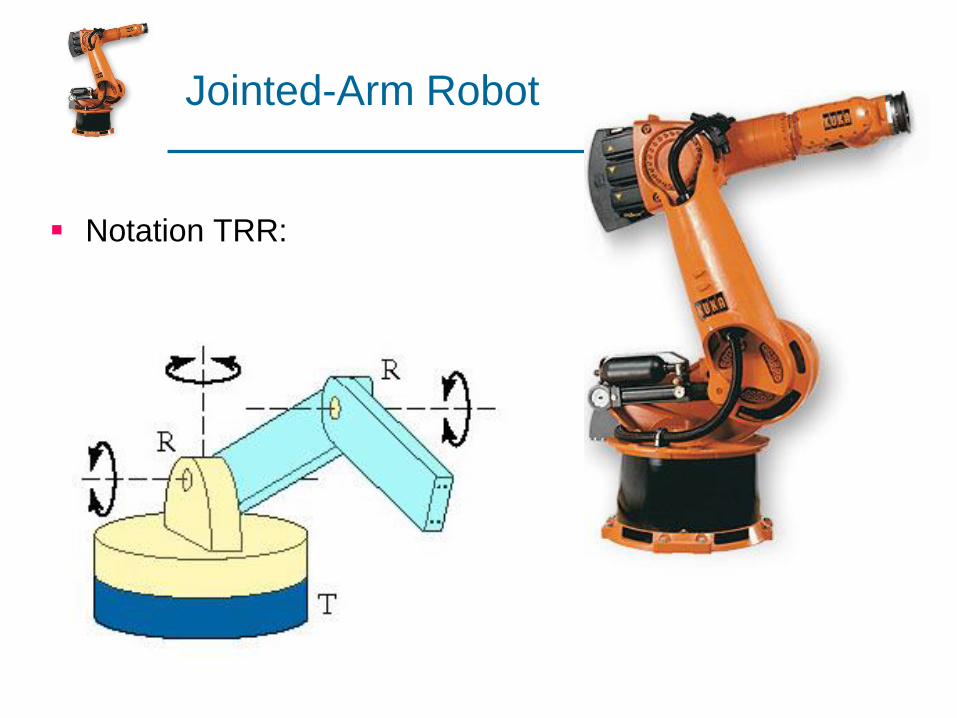
Jointed-Arm Robot
Notation TRR:
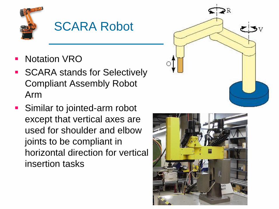
SCARA Robot
Notation VRO
SCARA stands for Selectively
Compliant Assembly Robot
Arm
Similar to jointed-arm robot
except that vertical axes are
used for shoulder and elbow
joints to be compliant in
horizontal direction for vertical
insertion tasks
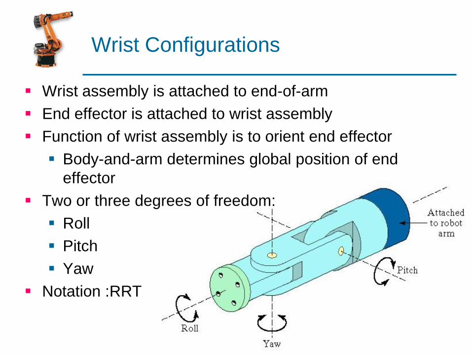
Wrist Configurations
Wrist assembly is attached to end-of-arm
End effector is attached to wrist assembly
Function of wrist assembly is to orient end effector
Body-and-arm determines global position of end
effector
Two or three degrees of freedom:
Roll
Pitch
Yaw
Notation :RRT
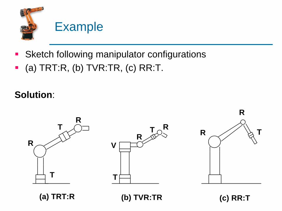
Example
Sketch following manipulator configurations
(a) TRT:R, (b) TVR:TR, (c) RR:T.
Solution:
T
R
T
V
(a) TRT:R
R
T
RT R
TR
R
(c) RR:T(b) TVR:TR
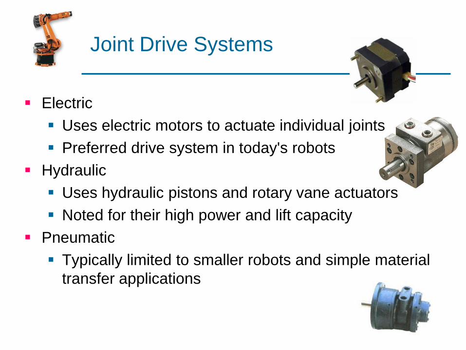
Joint Drive Systems
Electric
Uses electric motors to actuate individual joints
Preferred drive system in today's robots
Hydraulic
Uses hydraulic pistons and rotary vane actuators
Noted for their high power and lift capacity
Pneumatic
Typically limited to smaller robots and simple material
transfer applications
Types of Motion
Slew Motion
Each joint travels at a default speed from its initial position to the required
final destination.
Joint Interpolated Motion
Required the robot controller to calculate the time it will take each joint to
reach its destination at the commanded speed. Then it selects the
maximum time among this values and uses it as the time for the other axes.
Straight-line Interpolation motion
Requires the end of the end effector to travel along a straight line path
determined in rectangular coordinates.
Circular interpolation motion
Requires the robot controller to define the points of a circle in the workplace
based on a minimum of three specified positions. Normally consist of short
straight-line segments.
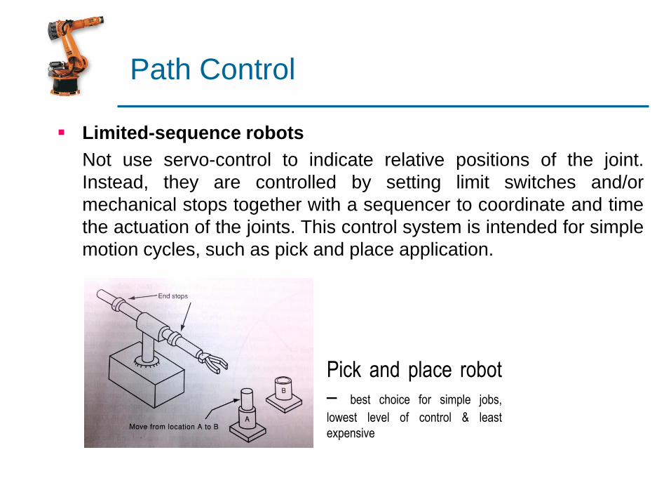
Path Control
Limited-sequence robots
Not use servo-control to indicate relative positions of the joint.
Instead, they are controlled by setting limit switches and/or
mechanical stops together with a sequencer to coordinate and time
the actuation of the joints. This control system is intended for simple
motion cycles, such as pick and place application.
Pick and place robot
– best choice for simple jobs,
lowest level of control & least
expensive
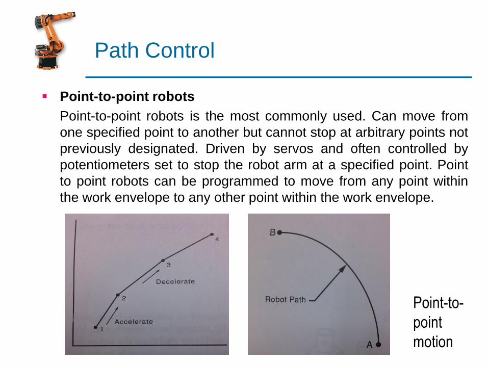
Path Control
Point-to-point robots
Point-to-point robots is the most commonly used. Can move from
one specified point to another but cannot stop at arbitrary points not
previously designated. Driven by servos and often controlled by
potentiometers set to stop the robot arm at a specified point. Point
to point robots can be programmed to move from any point within
the work envelope to any other point within the work envelope.
Point-to-
point
motion
Path Control
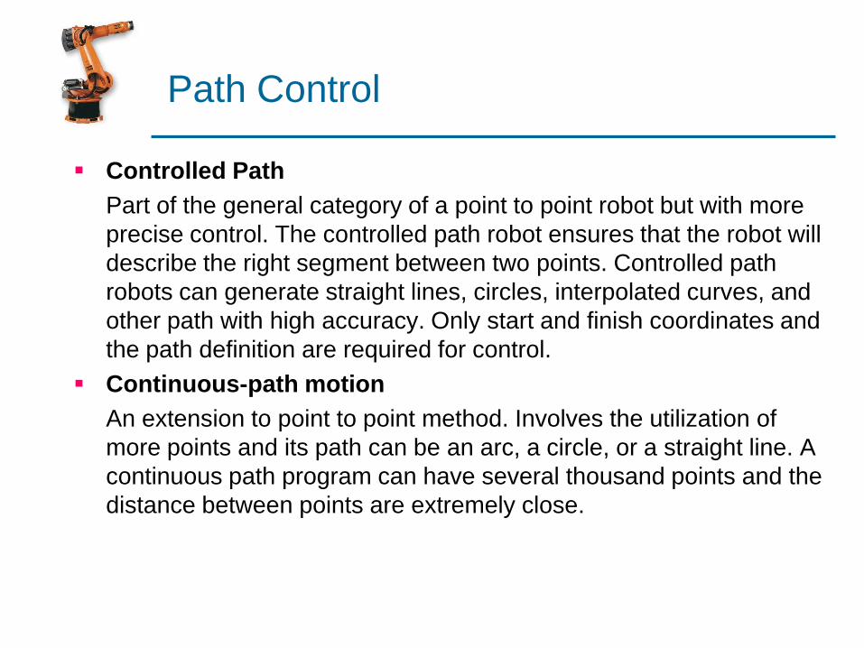
Controlled Path
Part of the general category of a point to point robot but with more
precise control. The controlled path robot ensures that the robot will
describe the right segment between two points. Controlled path
robots can generate straight lines, circles, interpolated curves, and
other path with high accuracy. Only start and finish coordinates and
the path definition are required for control.
Continuous-path motion
An extension to point to point method. Involves the utilization of
more points and its path can be an arc, a circle, or a straight line. A
continuous path program can have several thousand points and the
distance between points are extremely close.
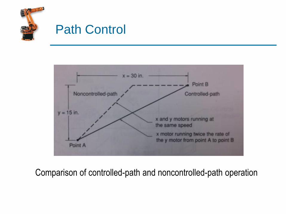
Path Control
Comparison of controlled-path and noncontrolled-path operation
Intelligence Level
Robot systems are usually classified as low-technology and high-
technology groups.
Low-technology robots do not use servo control to indicate relative
positions of the joints.
High-technology robots are servo-controlled systems that accept
more sophisticated sensors and complex programming languages.
The intelligent control robot is capable of performing some of the
functions as tasks carried out by human beings. It can detect
changes in the work environment by means of sensory perception.
Aims of the intelligent robot systems: Performing tasks such as
moving among a variety of machines and equipment on the shop
floor and avoiding collision; recognizing, picking, and properly
gripping the correct raw material or work piece; transporting a
workpiece to a machine for processing or inspection; and
assembling the components into final product.

Control System
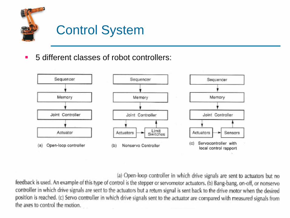
Control systems can be divided into two types, called open-loop or
closed-loop systems.
Stepper motor is an example of open-loop system where the control
signals directly position the motor without feedback.
Two types of closed-loop systems in industrial robot are servo and
non-servo. Servo refers to a continuous position-controlling device.
A non-servo robot may use a limit switch to indicate that the robot
has reached the desired position.
Both open-loop and closed-loop system may be used in overall
robot manipulator.
Control System
5 different classes of robot controllers:

Control System
5 different classes of robot controllers:

Control System
Closed loop for non-servo robot
Controller
Valve
Actuator
axis
The controller sends
a drive signal to a
valve that energizes
the actuator. When
the axis reaches the
desired position, a
signal is sent back to
the controller to
close the valve.
Control System
Servo Robot Operation
The servo robot has a basic controlled system that receives its
reference position signal from the sequence controller.
Comparison between the desired and current position produces
error signal.
The error signal converted to the proper form and applied to the
actuator.
With proper design, the action of this feedback is very smooth and
reliable.
Control System
Servo-controlled robot can move to any point within its work
envelope.
Control of velocity, acceleration, and deceleration between program
points is also possible.
Programming may be accomplished by teach pendant, by external
control or off-line programming.
The memory of the computer is usually sufficient to store thousands
of program points.
The characteristics of a servo-controlled robot may be observed in
the smooth motions with control of speed and acceleration.
Servo-controlled robot has a greater flexibility and ability to
accomplish variety of tasks.
Control System
Robot and workcell control system
Most robot control units today are based on a microcomputer
system, which can sense, evaluate, make decisions, and interact
with their environment.
When a robot executes a stored program for instructions that
defines the sequence of motions, and positions in the work cycle,
the program may also include instructions for other functions, such
as interacting with external equipment, responding to sensors, and
processing data.
The activities of such coordination must be established by means of
control-system requirements and workcell control.

Control System
Robot and workcell control system

Control System
Programmable Logic Controller
Originally designed to replace relay logic and to provide flexibility in
control based on programming and executing instructions.
The advantages of PLCs:
Easy to program and install
The speed with internal timers operate in much faster than
conventional time-delay relay systems.
Access to PLCs is restricted by hardware features, such as
keylocks, and by software features, such as password.
Problem-solving with PLCs is a major advantage over any other
type of control system.
Control System
PLCs can be designed with communications capabilities that
allow them to converse with local and remote computer systems
or to provide human interfaces.
PLCs are extremely reliable and easier-to-maintain control
devices and can be obtained in forms that can survive and
function in harsh conditions.
PLCs require less floor space than relay logic controls.

Control System
Block diagram of a PLC
Programming
terminal
Input CPU Memory Output
Power supply
Input
devicesOutput
devices

Control System
Input/Output
The input interface provides a connection to the machine or process being
controlled. The principal function of this interface is to receive and convert
field signals into a form that can be used by the CPU.
The output interface performs the opposite function of the input interface. It
takes signals from the CPU and translates them into forms that are
appropriate to produce control actions by external devices such as
solenoids, motor starters and so on.
Memory & CPU
Memory and CPU provide the main intelligence of a PLC. Fundamental
operating information is stored in memory as a pattern of electrical charges
(bits) that is organized into basic working groups called words. Each word
stored in memory is a piece of data, an instruction, or part of an instruction.
The CPU performs logical decisions, drives the outputs, and continually
refers to the program stored in memory for instructions concerning its next
action for reference data.
Control System
Programming language have many forms and each PLC
manufacture uses a slightly different language.
Most of PLC languages are based on ladder logic, which is
advanced form of relay logic.
Control System
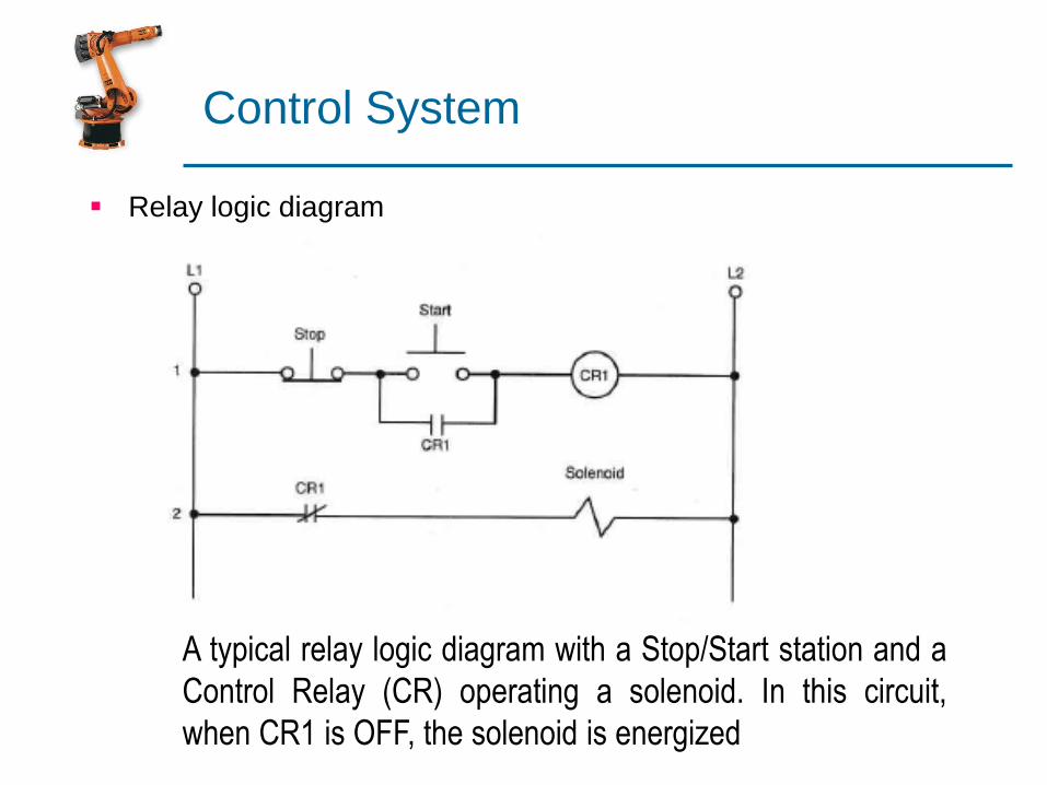
Relay logic diagram
A typical relay logic diagram with a Stop/Start station and a
Control Relay (CR) operating a solenoid. In this circuit,
when CR1 is OFF, the solenoid is energized

Control System
Ladder logic diagram
The same diagram drawn in ladder logic. The input and
output devices are now represented by numbers. These
numbers are referred to as address

Control System
The basic points regarding ladder logic diagram.
All devices that represent resistive or inductive loads to the circuit are
shown at the right of the diagram.
All devices that represent or make or break electrical contacts are shown at
the left of the diagram.
Devices connected in parallel with other devices are often called branches.
Each complete horizontal line of a ladder diagram is typically referred to as
a rung.
Electrical devices are shown in their conditions. An NC contact would be
shown as normally closed, or represented as XIO (examine if open), and an
NO contact would appear as a normally open device or represented as XIC
(examine if closed). All contacts associated with a device will change state
when the device is energized.
Devices that perform a start function are connected in series; devices that
perform a start function are connected in parallel
The two parallel vertical lines where all rungs are connected provide power
to the components.
Control System
Programming terminal
A programming device, or programming terminal, allows a user to
enter instructions into memory in the form of a program. The
programming device produces the pattern of electrical signals that
correspond to the symbols, letters, or numbers entered by the user.
Many PLCs can now be programmed, using a teach pendant or
personal computer (PC).
Power Supply
The power supply provides all the voltage levels needed to operate
the PLC.
Control System
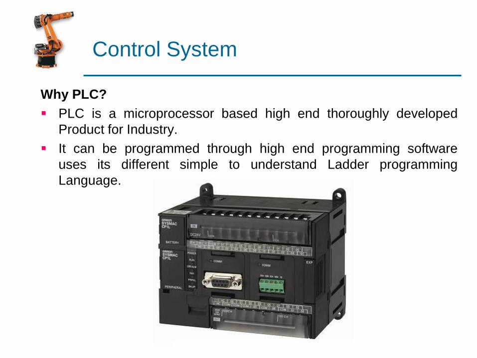
Why PLC?
PLC is a microprocessor based high end thoroughly developed
Product for Industry.
It can be programmed through high end programming software
uses its different simple to understand Ladder programming
Language.
Control System
Proportional-Integral-Derivative (PID)
Continuous process cannot be accomplished fast enough by a PLC
On-Off control.
PID control is the most often used in continuous process.
Many medium-size PLCs and all large PLCs have PID control
functions, which are able to execute process control effectively.
PID control keeps the output at a set level even though varying
process parameters may tend to cause the output to vary from the
desired set point.
PID promptly and accurately changes the process level from one
set point to another set point level.

Control System
Proportional-Integral-Derivative (PID)

The Characteristics of P, I, and D controllers
A proportional controller (Kp) will have the effect of reducing the rise time
and will reduce, but never eliminate, the steady-state error.
An integral control (Ki) will have the effect of eliminating the steady-state
error, but it may make the transient response worse.
A derivative control (Kd) will have the effect of increasing the stability of
the system, reducing the overshoot, and improving the transient
response.
Control System
Proportional Control
By only employing proportional control, a steady state error
occurs.
Proportional and Integral Control
The response becomes more oscillatory and needs longer to
settle, the error disappears.
Proportional, Integral and Derivative Control
All design specifications can be reached.
Control System
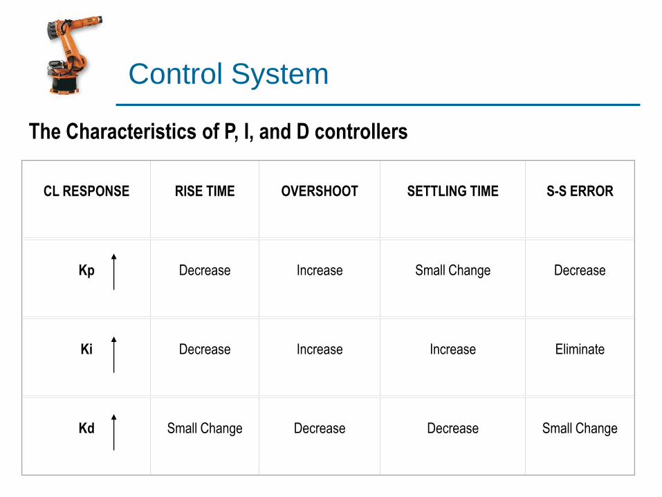
CL RESPONSE RISE TIME OVERSHOOT SETTLING TIME S-S ERROR
Kp Decrease Increase Small Change Decrease
Ki Decrease Increase Increase Eliminate
Kd Small Change Decrease Decrease Small Change
The Characteristics of P, I, and D controllers
Control System
Control System
Microprocessor Unit
The microprocessor plays a dominant role in computer technology
and has contributed uniquely in the development of many new
concepts and design techniques for modern industrial systems.
The development of the microprocessor has allowed the robot
industry to develop to its present state.

Control System
Universal Robot Controller
Programs for robots can be divided into two areas; operating
system and application programs.
Operating systems, sometimes called control programs are
developed by the manufacturer and are fixed for each robot model
and cannot be changed or exchanged with other manufacturers’
robots.
Operating systems supply the intelligence that enables the robot to
receive, understand, and carry out tasks that are given.
Application programs are known as user’s program.
These programs contain positional data, axis velocity, geometric
axis moves, gripper instruction, and interface instructions to other
devices and equipment.
Control System
Interfacing
Interfacing is the communication between various components of
the robot workcell that establishes a link between the peripheral
devices, the controller, and the manipulator’s end effector.
The interfacing operation requires the programmer of the robot to
assign various lines as either input lines or output lines.
The interfacing operation may be developed through a remote
connection, this process allows the operator of the workstation to
control different work cells from a central location.
Status signals from the robot can be sent to the remote workstation,
and signals from the remote workstation can be sent to the robot
controller.
In many high-technology automated systems, computer are
interfaced with the controller. The program are written on the
computer and then downloaded to the robot controller.
Control System
Workcell Control
A robotic workcell may be defined as a cluster of one or more
robots and several machine tools or transfer lines that are
interconnected in such a way that they work together
simultaneously.
The workcell controller performs several important functions in the
robot installation. These functions can be divided into three main
categories:
Sequence control
Operator interface
Safety monitoring

Control System
Workcell Control
Typical workcell: A robot is positioned to service a number of machine clusters
Control System
Sequence Control
The sequence is determined not only by controlling the activities as
a function of time, it is also determined by using interlocks to ensure
that certain elements of the work cycle are completed before other
elements are started.
In a loading and unloading application input/output, interlocks in
sequence control are used for purposes such as the following:
Making sure that the part is at the pickup location before the
robot attempt to grasp it.
Ensuring that the part is properly loaded into the machine before
the processing cycle begins.
Indicating to the robot that the machine cycle is completed and
the part is ready for unloading.
Control System
Operator Interface
Means for the operator to interact with the robot cell must be
provided. Reasons for establishing such interface include the
following:
Programming robot
Participation in the workcell. An operator and the robot each
perform a portion of the workcell in the cell. The operator
typically accomplished tasks that require judgment or sensory
capabilities that the robot does not possess.
Data entry, such as part identification or part dimension.
Emergency stopping of the cell activities.
Control System
Safety Monitoring
A more automatic and reliable means of protecting the cell
equipment and people who might wander into the work zone is
called safety monitoring.
Safety monitoring is a workcell control function in which sensors are
used to monitor the status and activities of the cell and detect the
unsafe or potential unsafe conditions.
Various sensors can be used to implement a safety monitoring
system in a robot cell that may include limit switch, temperature
sensors, pressure-sensitive floor mats, light beams combined with
photosensitive sensors, and machine vision systems.

Control System
Safety Monitoring
The safety monitoring system is programmed to respond to various
hazard conditions in different ways. These responses might include
one or more of the following:
Complete stoppage cell.
Slowing down the robot speed to a safe level.
Warning buzzers to alert maintenance personnel of a safety
hazard in the cell.
Special program subroutines to permit the robot to recover from
a particular unsafe event.
Robot Programming
Leadthrough programming
Work cycle is taught to robot by moving the
manipulator through the required motion cycle and
simultaneously entering the program into
controller memory for later playback
Robot programming languages
Textual programming language to enter
commands into robot controller
Simulation and off-line programming
Program is prepared at a remote computer
terminal and downloaded to robot controller for
execution without need for leadthrough methods
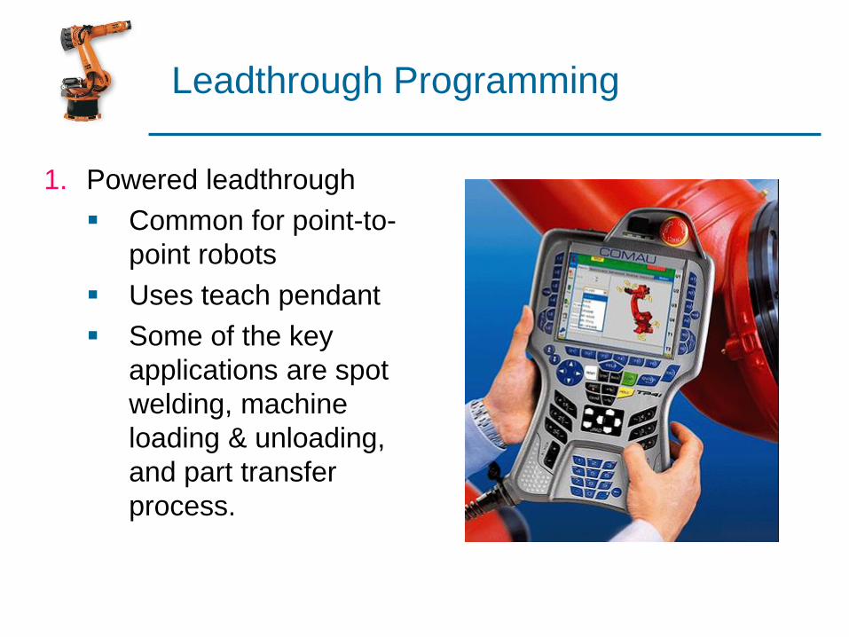
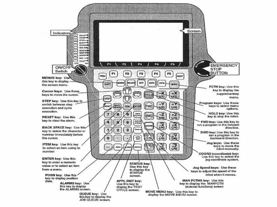
Leadthrough Programming
1. Powered leadthrough
Common for point-to-
point robots
Uses teach pendant
Some of the key
applications are spot
welding, machine
loading & unloading,
and part transfer
process.
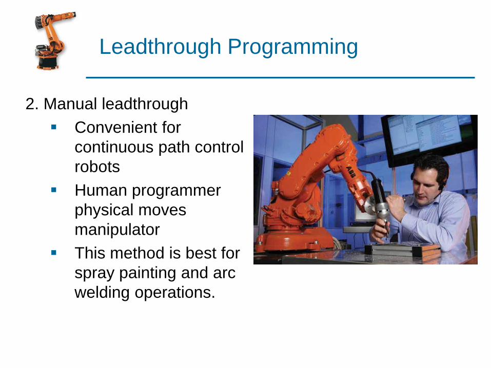
Leadthrough Programming
2. Manual leadthrough
Convenient for
continuous path control
robots
Human programmer
physical moves
manipulator
This method is best for
spray painting and arc
welding operations.

Leadthrough Programming
Advantages
Advantages:
Easily learned by shop personnel
Logical way to teach a robot
No computer programming
Disadvantages:
Downtime during programming
Limited programming logic capability
Not compatible with supervisory control
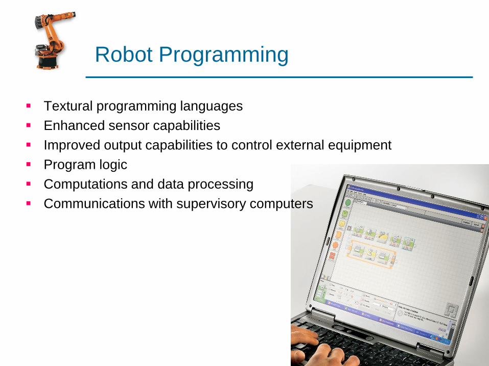
Robot Programming
Textural programming languages
Enhanced sensor capabilities
Improved output capabilities to control external equipment
Program logic
Computations and data processing
Communications with supervisory computers

Coordinate Systems
World coordinate system Tool coordinate system
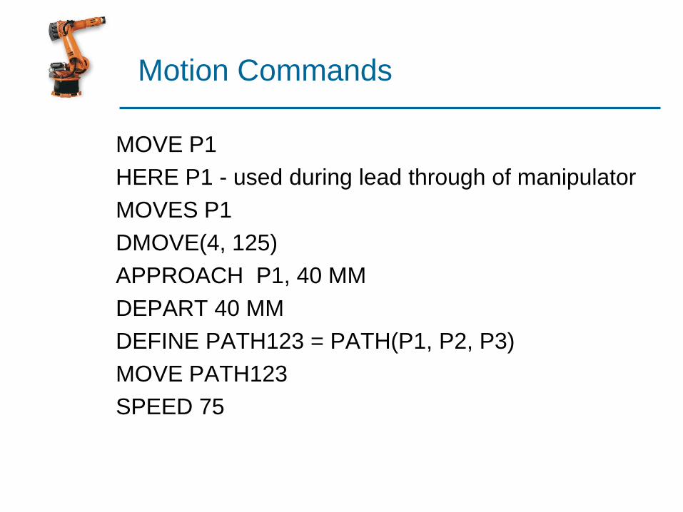
Motion Commands
MOVE P1
HERE P1 - used during lead through of manipulator
MOVES P1
DMOVE(4, 125)
APPROACH P1, 40 MM
DEPART 40 MM
DEFINE PATH123 = PATH(P1, P2, P3)
MOVE PATH123
SPEED 75
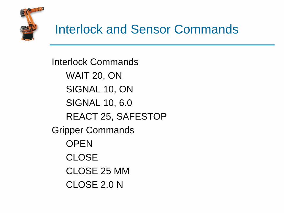
Interlock and Sensor Commands
Interlock Commands
WAIT 20, ON
SIGNAL 10, ON
SIGNAL 10, 6.0
REACT 25, SAFESTOP
Gripper Commands
OPEN
CLOSE
CLOSE 25 MM
CLOSE 2.0 N

Simulation and Off-Line Programming
END