Chapter-3_Mar-2013_508
46
Chapter 3 Biological Treatment Processes 3.1 Introduction Biological treatment processes are systems that use microorganisms to degrade organic contaminants from wastewater. In wastewater treatment, natural biodegradation processes have been contained and accelerated in systems to remove organic material and nutrients. The microorganisms metabolize nutrients, colloids, and dissolved organic matter, resulting in treated wastewater. Excess microbial growth is removed from the treated wastewater by physical processes. Biological processes are the preferred way of treatment as they are cost effective in terms of energy consumption and chemical usage. For example, biological nutrient removal (BNR) has emerged as the preferred approach for nutrient removal. BNR processes involve modifications of biological treatment systems so that the microorganisms in these systems can more effectively convert nitrate nitrogen into inert nitrogen gas and trap phosphorus in solids that are removed from the effluent. IFAS (Integrated Fixed-film Activated Sludge, MBBR (Moving Bed Bio-Reactor), and MBR (Membrane Bio-Reactor) processes have all become established technologies for situations where reactor volume is at a premium and are particularly well suited to BNR applications. In the last several years, nitritation/denitritation and deammonification processes have made the transition from Europe and are beginning to be implemented at large US utilities. 3.2 Technology Assessment Table 3.1 presents a categorized list of established, innovative, emerging and research biological treatment process technologies. The list includes most established biological treatment processes and recent developments in cost-effective methods to retrofit older systems or result in systems with smaller footprints. Experience with operation of biological systems and the ongoing effort to maximize process performance have resulted in modification or development of several biological treatment processes that warrant discussion in this chapter on innovative, adaptive use, emerging, and research technologies. Generally, the improvements in established biological treatment processes provide treatment of recycle streams, optimize recycle, and maximize nutrient-removal capabilities. Selecting and classifying technologies for inclusion in this report was a challenging task. Biological processes in particular are constantly evolving such that in many cases the same process configuration will be known under two or more names or the same name may be applied to slightly different process configurations. Rather than adopting a defined and named configuration, current practice is to use modern process modeling to develop a site specific process configuration. Consequently, skilled practitioners can apply the fundamentals of process engineering to develop an essentially infinite range of site specific process Wastewater Treatment and In-Plant Wet Weather Management 3-1
-
Upload
pranav-nakhate -
Category
Documents
-
view
32 -
download
3
description
213
Transcript of Chapter-3_Mar-2013_508

Chapter
3 Biological Treatment Processes
3.1 Introduction
Biological treatment processes are systems that use microorganisms to degrade organic contaminants from wastewater. In wastewater treatment, natural biodegradation processes have been contained and accelerated in systems to remove organic material and nutrients. The microorganisms metabolize nutrients, colloids, and dissolved organic matter, resulting in treated wastewater. Excess microbial growth is removed from the treated wastewater by physical processes.
Biological processes are the preferred way of treatment as they are cost effective in terms of energy consumption and chemical usage. For example, biological nutrient removal (BNR) has emerged as the preferred approach for nutrient removal. BNR processes involve modifications of biological treatment systems so that the microorganisms in these systems can more effectively convert nitrate nitrogen into inert nitrogen gas and trap phosphorus in solids that are removed from the effluent. IFAS (Integrated Fixed-film Activated Sludge, MBBR (Moving Bed Bio-Reactor), and MBR (Membrane Bio-Reactor) processes have all become established technologies for situations where reactor volume is at a premium and are particularly well suited to BNR applications. In the last several years, nitritation/denitritation and deammonification processes have made the transition from Europe and are beginning to be implemented at large US utilities.
3.2 Technology Assessment
Table 3.1 presents a categorized list of established, innovative, emerging and research biological treatment process technologies. The list includes most established biological treatment processes and recent developments in cost-effective methods to retrofit older systems or result in systems with smaller footprints. Experience with operation of biological systems and the ongoing effort to maximize process performance have resulted in modification or development of several biological treatment processes that warrant discussion in this chapter on innovative, adaptive use, emerging, and research technologies. Generally, the improvements in established biological treatment processes provide treatment of recycle streams, optimize recycle, and maximize nutrient-removal capabilities.
Selecting and classifying technologies for inclusion in this report was a challenging task. Biological processes in particular are constantly evolving such that in many cases the same process configuration will be known under two or more names or the same name may be applied to slightly different process configurations. Rather than adopting a defined and named configuration, current practice is to use modern process modeling to develop a site specific process configuration. Consequently, skilled practitioners can apply the fundamentals of process engineering to develop an essentially infinite range of site specific process
Wastewater Treatment and In-Plant Wet Weather Management 3-1

Emerging Technologies March 2013
configurations beyond those presented in this report. Future updates to this report will no doubt rename, reclassify, or even remove some of the process configurations currently included as the report evolves to keep up with the technology developments and engineering practice.
An evaluation of the innovative technologies identified for biological treatment processes relative to their state of development, applicability, potential for effluent reuse and the potential benefits of the technology is presented in Figure 3.1. Summary sheets for each innovative, adaptive use, emerging, and research technology are provided at the end of the chapter. The innovative technologies are: Bioaugmentation, Deammonification, Nitritation/Denitritation, Deep-Shaft Activated Sludge/VERTREAT™, Cyclic Metabolic Environment and Magnetite Ballasted Activated Sludge processes. The adaptive use technologies are: the Biological-Chemical Phosphorus and Nitrogen Removal (BCFS) Process, the Modified University of Cape Town (MUCT) Process, the Westbank Process, and the Modified Anaerobic/Oxic (A/O) Process. These processes have various configurations and modules to fit the specific needs of any individual treatment plant. Most of these technologies can be easily retrofitted into existing treatment systems that enable treatment processes to achieve better nutrient removal.
Emerging technologies included at the end of this chapter are: Membrane Biofilm Reactor (MBfR), Vacuum Rotation Membrane (VRM), OpenCel Focused Pulse, Integrated Fixed-film Activated Sludge (IFAS) Systems with Biological Phosphorus Removal, Multi-Stage Activated Biological Process (MSABP™) and Aerobic Granular Sludge Process (AGSP). Three technologies in the research stage of development are included: Anaerobic Migrating Blanket Reactor (AMBR®), Anaerobic Membrane BioReactor (An-MBR), and Microbial Fuel Cell (MFC) Based Treatment System.
Knowledge about technologies tends to evolve. The information provides a snapshot at a point in time; what is understood at one point in time may change as more information develops. This includes knowledge about operating mechanisms as well as the relative and absolute costs and features of a particular technology. Inquiries into the current state of knowledge are an important step when considering implementation of any technology.
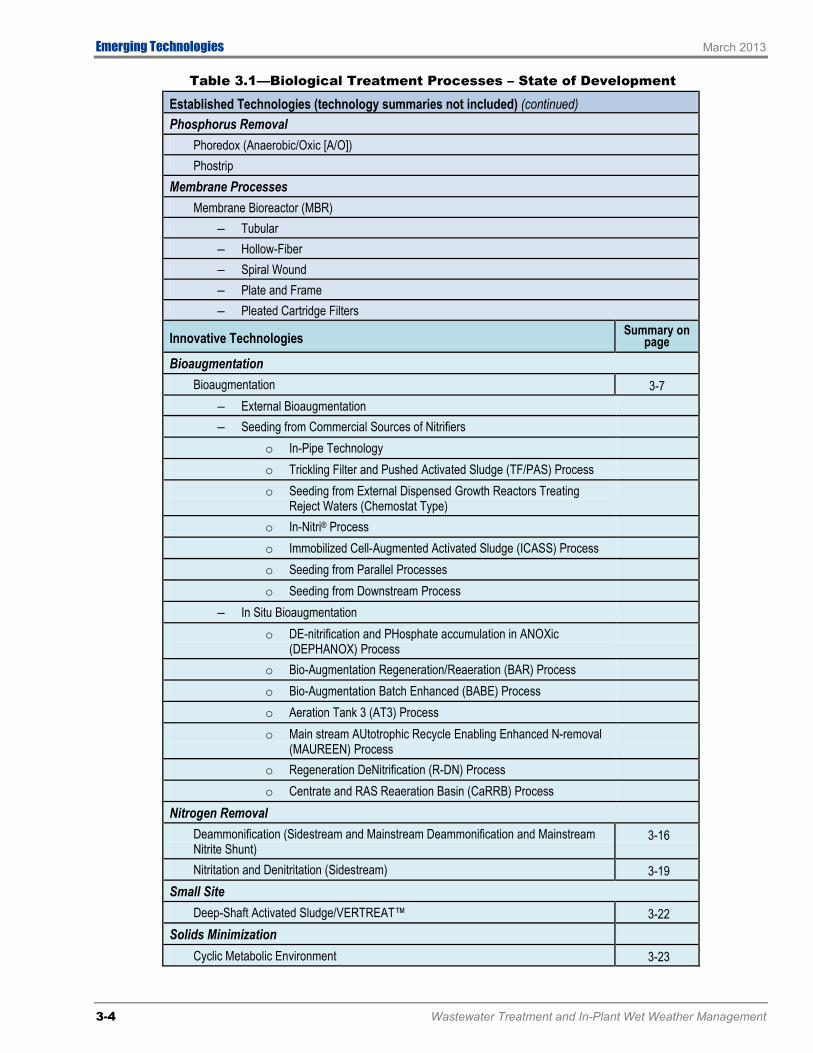
Table 3.1—Biological Treatment Processes – State of Development
Established Technologies (technology summaries not included) Anaerobic Processes
Anaerobic Attached Growth System – Upflow Packed-Bed Attached Growth Reactor – Upflow Attached Growth Anaerobic – Expanded-Bed Reactor (Anaerobic Expanded Bed Reactor [AEBR]) – Downflow Attached Growth Process
Anaerobic Contact Process Anaerobic Sequencing Batch Reactor (ASBR®) Upflow Anaerobic Sludge Blanket (UASB) ANFLOW (ANaerobic FLuidized Bed Reactor)
BOD Removal and Nitrification Biolac-Aerated Lagoon Complete Mix-Activated Sludge (CMAS) Process Contact Stabilization Conventional Extended Aeration
3-2 Wastewater Treatment and In-Plant Wet Weather Management

March 2013 Emerging Technologies
Table 3.1—Biological Treatment Processes – State of Development
Established Technologies (technology summaries not included) (continued) Countercurrent Aeration System (CCAS™) Cyclic Activated Sludge System (CASS™) Facultative and Aerated Lagoons High-Purity Oxygen (HPO) Intermittent Cycle Extended Aeration System (ICEASTM) Kraus Process Oxidation Ditch/Aerated Lagoons Sequencing Batch Reactor (SBR) Staged Activated-Sludge Process Step Feed
Biofilm Processes Biological Aerated Filters (BAF)
– Biofor® – Biostyr®
Fluidized Bed Bioreactor (FBBR) Integrated fixed-Film Activated Sludge (IFAS)
– IFAS – Submerged Mobile Media – IFAS – Submerged Fixed Media
Moving-Bed Bio Reactor (MBBR) Process Rotating Biological Contactor (RBC) Submerged Rotating Biological Contactor (SRBC) Trickling Filter (TF) Trickling Filter /Solids Contactor (TF/SC)
Nitrogen Removal Bardenpho® (Four Stage) BiodenitroTM Denitrification Filter Ludzack-Ettinger Modified Ludzack-Ettinger (MLE) OrbalTM Process SchreiberTM Process Simultaneous Nitrification denitrificatioN (SNdN) Process Step Feed (Alternating Anoxic and Aerobic) Wuhrman
Nitrogen and Phosphorus Removal Anaerobic/Anoxic/Oxic (A2/O) Bardenpho® (Five Stage) Johannesburg Process Step Feed BNR Process University of Cape Town (UCT) Virginia Initiative Plant (VIP)
Wastewater Treatment and In-Plant Wet Weather Management 3-3
Emerging Technologies March 2013
Table 3.1—Biological Treatment Processes – State of Development
Established Technologies (technology summaries not included) (continued) Phosphorus Removal
Phoredox (Anaerobic/Oxic [A/O]) Phostrip
Membrane Processes Membrane Bioreactor (MBR)
– Tubular – Hollow-Fiber – Spiral Wound – Plate and Frame – Pleated Cartridge Filters
Innovative Technologies Summary on page
Bioaugmentation Bioaugmentation 3-7
– External Bioaugmentation – Seeding from Commercial Sources of Nitrifiers
o In-Pipe Technology o Trickling Filter and Pushed Activated Sludge (TF/PAS) Process o Seeding from External Dispensed Growth Reactors Treating
Reject Waters (Chemostat Type)
o In-Nitri® Process o Immobilized Cell-Augmented Activated Sludge (ICASS) Process o Seeding from Parallel Processes o Seeding from Downstream Process
– In Situ Bioaugmentation o DE-nitrification and PHosphate accumulation in ANOXic
(DEPHANOX) Process
o Bio-Augmentation Regeneration/Reaeration (BAR) Process o Bio-Augmentation Batch Enhanced (BABE) Process o Aeration Tank 3 (AT3) Process o Main stream AUtotrophic Recycle Enabling Enhanced N-removal
(MAUREEN) Process
o Regeneration DeNitrification (R-DN) Process o Centrate and RAS Reaeration Basin (CaRRB) Process
Nitrogen Removal Deammonification (Sidestream and Mainstream Deammonification and Mainstream Nitrite Shunt)
3-16
Nitritation and Denitritation (Sidestream) 3-19 Small Site
Deep-Shaft Activated Sludge/VERTREAT™ 3-22 Solids Minimization
Cyclic Metabolic Environment 3-23
3-4 Wastewater Treatment and In-Plant Wet Weather Management

March 2013 Emerging Technologies
Table 3.1—Biological Treatment Processes – State of Development
Innovative Technologies (continued) Summary on page
Solids Settleability Magnetite Ballasted Activated Sludge 3-25
Adaptive Use Technologies Summary on page
Nitrogen and Phosphorus Removal Biological-Chemical Phosphorus and Nitrogen Removal (BCFS) Process 3-27 Modified University of Cape Town (MUCT) Process 3-29 Westbank Process 3-30
Phosphorus Removal Modified Anaerobic/Oxic (A/O) Process 3-31
Emerging Technologies Summary on page
Membrane Processes Membrane Biofilm Reactor (MBfR) 3-32 Vacuum Rotation Membrane (VRM®) System 3-34
Nitrogen Removal OpenCel Focused Pulse 3-35
Nitrogen and Phosphorus Removal Integrated Fixed-film Activated Sludge (IFAS) with Biological Phosphorus Removal 3-36
Solids Minimization Multi-Stage Activated Biological Process (MSABP™) 3-37
Solids Settleability Aerobic Granular Sludge Process (AGSP) 3-38
Research Technologies Summary on page
Anaerobic Processes Anaerobic Migrating Blanket Reactor (AMBR®) 3-41 Anaerobic Membrane BioReactor (An-MBR) 3-43
Electricity Generation Microbial Fuel Cell (MFC) Based Treatment System 3-45
Wastewater Treatment and In-Plant Wet Weather Management 3-5

Emerging Technologies March 2013
Process
Evaluation Criteria
Deve
lopm
ent
Appl
icabi
lity
Bene
fits
Impa
ct o
n Pr
oces
ses
Com
plex
ity
Air/O
dor E
miss
ions
Reus
e
Ener
gy
Foot
prin
t
Retro
fittin
g
Bioaugmentation
Bioaugmentation I, M, N, O F C, O In ▲
Nitrogen Removal
Deammonification I, M, O, P F, L O, S ▲ ▼ ▲ ▲
Nitritation/Denitritation I, M, O, N F, L O, S ▲ ▼ ▲ ▲
Small Site
Deep-Shaft Activated Sludge/VERTREATTM
M, N, O F C, O ▲ In ▲ ▲
Solids Minimization
Cyclic Metabolic Environment M, N F M, N ▲ In ▲ ▲ ▲
Solids Settleability
Magnetite Ballasted Activated Sludge M, N I C, I, O ▲ ▲ ▲ ▲ ▲ ▲
Key
Statement of Development
B = Bench scale I = Full-scale industrial applications M = Full-scale municipal applications O = Full-scale operations overseas P = Pilot N = Full-scale operations in North America
Applicability
F = Few plants I = Industrywide L = Primarily large plants S = Primarily small plants
Potential Benefits
C = Capital savings I = Intense operational demand O = Operational/maintenance savings S = Shock load capacity W = Wet weather load capacity E = Effluent quality
Effluent Reuse
Dp = Direct potable Dn = Direct nonpotable lp = Indirect potable In = Indirect nonpotable
Comparative Criteria
▲ Positive feature Neutral or mixed ▼ Negative feature
Figure 3.1—Evaluation of Innovative Biological Treatment Technologies
3-6 Wastewater Treatment and In-Plant Wet Weather Management
March 2013 Emerging Technologies
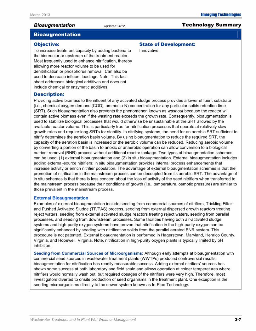
Bioaugmentation updated 2012 Technology Summary
Bioaugmentation
Objective: To increase treatment capacity by adding bacteria to the bioreactor or upstream of the treatment reactor. Most frequently used to enhance nitrification, thereby allowing more reactor volume to be used for denitrification or phosphorus removal. Can also be used to decrease influent loadings. Note: This fact sheet addresses biological additives and does not include chemical or enzymatic additives.
State of Development: Innovative.
Description: Providing active biomass to the influent of any activated sludge process provides a lower effluent substrate (i.e., chemical oxygen demand [COD], ammonia-N) concentration for any particular solids retention time (SRT). Such bioaugmentation also prevents the phenomenon known as washout because the reactor will contain active biomass even if the wasting rate exceeds the growth rate. Consequently, bioaugmentation is used to stabilize biological processes that would otherwise be unsustainable at the SRT allowed by the available reactor volume. This is particularly true for nitrification processes that operate at relatively slow growth rates and require long SRTs for stability. In nitrifying systems, the need for an aerobic SRT sufficient to nitrify determines the aeration basin volume. By using bioaugmentation to reduce the required SRT, the capacity of the aeration basin is increased or the aerobic volume can be reduced. Reducing aerobic volume by converting a portion of the basin to anoxic or anaerobic operation can allow conversion to a biological nutrient removal (BNR) process without additional reactor tankage. Two types of bioaugmentation schemes can be used: (1) external bioaugmentation and (2) in situ bioaugmentation. External bioaugmentation includes adding external-source nitrifiers; in situ bioaugmentation provides internal process enhancements that increase activity or enrich nitrifier population. The advantage of external bioaugmentation schemes is that the promotion of nitrification in the mainstream process can be decoupled from its aerobic SRT. The advantage of in situ schemes is that there is less concern about the loss of activity of the seed nitrifiers when transferred to the mainstream process because their conditions of growth (i.e., temperature, osmotic pressure) are similar to those prevalent in the mainstream process.
External Bioaugmentation Examples of external bioaugmentation include seeding from commercial sources of nitrifiers, Trickling Filter and Pushed Activated Sludge (TF/PAS) process, seeding from external dispersed growth reactors treating reject waters, seeding from external activated sludge reactors treating reject waters, seeding from parallel processes, and seeding from downstream processes. Some facilities having both air-activated sludge systems and high-purity oxygen systems have proven that nitrification in the high-purity oxygen can be significantly enhanced by seeding with nitrification solids from the parallel aerated BNR system. This procedure is not patented. External bioaugmentation is performed in Hagerstown, Maryland, Henrico County, Virginia, and Hopewell, Virginia. Note, nitrification in high-purity oxygen plants is typically limited by pH inhibition.
Seeding from Commercial Sources of Microorganisms: Although early attempts at bioaugmentation with commercial seed sources in wastewater treatment plants (WWTPs) produced controversial results, bioaugmentation for nitrification has readily measurable success. Adding external nitrifiers’ sources has shown some success at both laboratory and field scale and allows operation at colder temperatures where nitrifiers would normally wash out, but required dosages of the nitrifiers were very high. Therefore, most investigators diverted to onsite production of seed organisms in the treatment plant. One exception is the seeding microorganisms directly to the sewer system known as In-Pipe Technology.
Wastewater Treatment and In-Plant Wet Weather Management 3-7

Emerging Technologies March 2013
Bioaugmentation updated 2012 Technology Summary
Bioaugmentation (continued) In-Pipe Technology Process: This approach uses facultative microorganisms added to the sewer system upstream of the treatment facility with the goal of supplementing/modifying the biofilm on the walls of the sewer pipe. Using bioaugmentation in this way, the sewer is intended to become a part of the treatment process by reducing organic loading to the WWTP and transforming slowly degradable COD to readily degradable COD. Because sewer conditions generate relatively low sludge yield, waste activated sludge is decreased. Shearing of active biomass from the sewer walls provides indirect bioaugmentation to the downstream WWTP but would not include any significant nitrifier content. However, reducing COD loading and waste activated sludge production would result in an increased nitrifier fraction and an increased SRT for a given aerobic volume, thereby increasing nitrification capacity. In-Pipe Technology uses dosing units installed at strategic locations in the sewer system and resupplies them with concentrated microbial stock for a monthly fee per MGD treated.
Trickling Filter and Pushed Activated Sludge (TF/PAS) Process: The earliest example of external bioaugmentation with nitrifiers generated in the plant from a wastewater source is likely that of the TF/PAS process, whereby the total organic loading on the trickling filter is adjusted to achieve about 50 percent nitrification, thus seeding nitrifiers to a downstream activated sludge step with a low SRT of 2 to 4 days. It appears that the enhanced nitrification rates achieved could be because of both the effect of seeding and removing toxicants in the wastewater by pretreatment of the trickling filter.
3-8 Wastewater Treatment and In-Plant Wet Weather Management
Process Flow Diagram for Trickling Filter/Pushed Activated Sludge

March 2013 Emerging Technologies
Bioaugmentation updated 2012 Technology Summary
Bioaugmentation (continued) Seeding from External Dispersed Growth Reactors Treating Reject Waters (Chemostat Type): Some success has been reported with chemostats seeding batzch reactors simulating mainstream processes. Nitrifiers grown in batch-fed, sidestream chemostats are more effective in stimulating the process efficiency in the simulated mainstream reactors than are those grown in continuously fed chemostats. It has been shown that the specific nitrifier types grown in the sidestream chemostats are able to replace the microbial population in the mainstream reactors, suggesting that population diversity leads to more robust mainstream reactors.
Wastewater Treatment and In-Plant Wet Weather Management 3-9
Process Flow Diagram for Seeding from External Dispersed Growth

Emerging Technologies March 2013
Bioaugmentation updated 2012 Technology Summary
Bioaugmentation (continued) In-Nitri® Process: A patented process known as the Inexpensive Nitrification or In-Nitri® process uses a separate activated sludge process (aeration tank and clarifier) to treat the ammonia-rich sidestream from digester supernatant or dewatering. Compared to the mainstream, the sidestream has a much greater ammonia-N:COD ratio and usually a higher temperature, a nitrifying SRT can be maintained in a much smaller aeration basin. Further, the excess sludge from the sidestream system acts to augment the nitrifiers in the mainstream aeration tank. With the nitrifier bioaugmentation from the sidestream, the SRT required to achieve nitrification in the mainstream reactor is reduced. The process has the advantage of achieving year-round nitrification by reducing the SRT by adding only a small aeration tank and clarifiers for growing nitrifiers.
3-10 Wastewater Treatment and In-Plant Wet Weather Management
Process Flow Diagram for Inexpensive Nitrification
Immobilized Cell-Augmented Activated Sludge (ICAAS) Process: Immobilized cells are maintained for a specific treatment activity and are enriched in a reactor for bioaugmentation. The ICAAS process employs the immobilized cells that are activated and maintained for their specific treatment activity in an offline enricher reactor for bioaugmentation. The process has been effectively used in bench-scale reactors for treating hazardous-compound shock loads, to achieve enhanced nitrate removal and to increase general performance of the treatment process.
Seeding from Parallel Processes: Two schemes have been proposed to grow nitrifiers in a membrane bioreactor and seed a high-rate BNR process. However, results on pilot or full-scale trials have not yet been reported. Another approach included two parallel activated-sludge processes, tertiary nitrifying membrane bioreactor seeding paralleling a high-rate activated sludge process. Some process issues in this scheme are that membranes select for filtering, not settling biomass; seeding effectiveness is likely affected by predation; and the process fits only some nutrient-removal flow diagrams.

March 2013 Emerging Technologies
Bioaugmentation updated 2012 Technology Summary
Bioaugmentation (continued) Seeding from Downstream Process: This seeding process was developed for the main treatment plant in Vienna, Austria. The plant uses two stages of activated sludge in which the first stage is operated at a short (2-4 day) SRT and the second stage is operated at a long SRT for nitrification/denitrification. In this scheme, nitrifying mixed liquor is wasted from the second stage to the first stage, resulting in some nitrification in the first stage. Under normal circumstances10 to 40 percent of the influent is bypassed to the second stage to provide carbon for denitrification. A similar process is operated at the Howard F Curren WWTP in Tampa Florida where the first stage operates as a high purity oxygen activated sludge process receiving WAS from the second stage nitrification process thereby providing some nitrification in the first stage.
In Situ Bioaugmentation Separate-stage nitrification processes, in which carbon is removed in an initial biological stage and then followed by a separate-stage nitrification process, are the first examples of in situ bioaugmentation. A three-sludge system incorporating separate-stage nitrification was promoted as a preferred technology in 1970s. The main reason for this was that the separate steps of carbon removal, nitrification, and denitrification could each be optimized. Fixed-film systems have also been used for separate stage nitrification. The purpose of these systems was threefold: (1) use of media with high-mass-transfer rates; (2) use of recirculation to improve media-wetting and gain maximum nitrifying biofilm coverage and minimization of influent solids to avoid competition for oxygen from heterotrophs; and (3) the control of predators with flooding and alkaline treatment.
DE-nitrification and PHosphate accumulation in ANOXic (DEPHANOX) Process: This process includes a combination of suspended growth and fixed-film systems in separate stages. DEPHANOX is based on the phenomenon of simultaneous denitrification and phosphate accumulation in the anoxic zone. The solids removed at the primary settling tank are combined with the nitrified wastewater to provide the carbon source required for denitrification. The nitrification stage is a biofilm reactor in standard DEPHANOX applications. A modified approach is to use a suspended biomass reactor for nitrification but to follow it with a clarifier so that the nitrifying biomass is kept separate from the phosphorus accumulating and denitrifying biomass.
Wastewater Treatment and In-Plant Wet Weather Management 3-11
Process Flow Diagram for DEPHANOX Process
Bio-Augmentation Regeneration/Reaeration (BAR) Process: In the Bio-Augmentation R Process, in the Czech Republic the R stands for regeneration zone, and in the United States the R stands for reaeration. The BAR process simply recycles the ammonia-laden filtrate or centrate from dewatering of aerobically digested sludge to a reaeration (regeneration) tank and receives the entire return activated sludge flow into an aeration tank. The high ammonia concentration and elevated temperature in that tank promote nitrification and develop a concentrated culture of nitrifiers. The mixed liquor from the reaeration (regeneration) zone flows to the aeration basin properly seeding it with nitrifiers. A key difference between the BAR process and In-Nitri is that introduction of returned activated sludge (RAS) from the mainstream reactor allows the seed nitrifiers to be incorporated into already well-developed flocs, thereby providing some protection against environmental

Emerging Technologies March 2013
Bioaugmentation updated 2012 Technology Summary
Bioaugmentation (continued) shock when they enter the main aeration basin. The lack of a clarifier or other means to concentrate the biomass concentration in the nitrifier seed reactor reduces the degree of control that is available using In-Nitri. The BAR process was independently developed in the United States and Czech Republic.
Process Flow Diagram for BAR Process
Bio-Augmentation Batch Enhanced (BABE) Process: The patented BABE process is composed of a sequencing batch reactor (SBR) that is fed with the reject water from the sludge dewatering process and a portion of the RAS from the treatment system. The BABE process is similar to the BAR process, but configuring the nitrifying seed reactor as an SBR provides a means to control the biomass concentration there. Longer sludge age can be achieved in the SBR tank, which helps the nitrifying bacteria to adapt and grow in the BABE reactor. The SBR follows the phases of the standard treatment cycle, i.e., fill and aerate, react, settle, and waste.
3-12 Wastewater Treatment and In-Plant Wet Weather Management
Flow Diagram for BABE Process

March 2013 Emerging Technologies
Bioaugmentation updated 2012 Technology Summary
Bioaugmentation (continued) Aeration Tank 3 (AT3) Process: The AT3 process is similar to BAR process but differs in sending a smaller fraction of the RAS to the reaeration tank, and it has a downstream anoxic zone. The process goal is to stop the nitrification process at the nitrite stage (nitritation) by control of dissolved oxygen and pH to reduce the consumption of carbon and oxygen for complete denitrification. Adding an external carbon source at the anoxic zone might be needed to accomplish denitrification.
Mainstream AUtotropic Recycle Enabling Enhanced N-removal (MAUREEN) Process: The MAUREEN process includes a sidestream bioreactor to allow for nitrification and denitrification of the centrate stream. The configuration is similar to the AT3 process but has biomass recycling at the sidestream reactor. This process was developed for the Blue Plains Advanced Wastewater Treatment Plan (AWTP) and provides significant flexibility when applied to the two-sludge system at the plant. The configuration includes preferential bioaugmentation of ammonia-oxidizing bacteria from the second to the first stage via the sidestream reactor and oxidation of ammonia in reject centrate to nitrite in the enrichment reactor, resulting in reduced power and chemical consumption. This process has the ability to fortify the second-stage system with a combination of primarily ammonia oxidizers and anoxic methanol-degrading bacteria produced in the sidestream reactor under conditions that would limit the presence of nitrite-oxidizing bacteria and heterotrophic bacteria. Supernatant from the sidestream process can be used for odor and corrosion control in the headworks or in process streams at the plant. Key to the success of the process is the physical configuration and selection of operating conditions of the sidestream reactor.
Wastewater Treatment and In-Plant Wet Weather Management 3-13
Process Flow Diagram for MAUREEN Process

Emerging Technologies March 2013
Bioaugmentation updated 2012 Technology Summary
Bioaugmentation (continued) Regeneration-DeNitrification (R-DN) Process: The R-DN process is identical to BAR process and involves filtrate or centrate bioaugmentation. It was independently developed in the Czech Republic and the United States.
Centrate and RAS Reaeration Basin (CaRRB) Process: Another named process that is identical to the BAR and R-DN processes.
Comparison to Established Technologies: Bioaugmentation processes can be used to reduce the bioreactor volume of many mainstream treatment processes. In general they reduce the loading to the mainstream plant by pretreating the high-strength recycle flow while providing the mainstream plant with seed organisms generated in the sidestream reactor. Depending on the needs of the mainstream process, the sidestream process can be configured to augment populations of both nitrifiers and denitrifiers. The biomass generated by the sidestream reactor allows the mainstream reactor to be smaller in volume while providing the required SRT. The reduction in required volume can allow a portion of the basin volume to be converted to provide denitrification or phosphorus removal. By pretreating the sidestream before blending into the mainstream process, loading and performance can be stabilized.
Available Cost Information: Approximate Capital Cost: Cost information is not available from vendors. However, bioaugmentation processes save capital costs in the main treatment systems because of reduced reactor volumes via the augmentation of nitrifying bacteria. Approximate O&M Costs: The operating costs are mainly related to mixing and aeration requirements and depend on local conditions and the available equipment. Bioaugmentation processes also save operating costs in the main treatment through the augmentation of nitrifying bacteria. Actual costs were not disclosed.
Vendor Name(s): In-Pipe Technology 100 Bridge Street Wheaton, IL 60187 Telephone: 630-871-5844 Email: [email protected] Web site: www.in-pipe.com
DHV Water BV, BABE Process P.O. Box 484 3800 AL Amersfoort, The Netherlands Telephone: 0031-33-468-2200 Email: [email protected] Web site: http://www.dhv.com/water/
M2T (Mixing and Mass Transfer Technologies), In-Nitri Process P.O. Box 315 State College, PA 16804 Telephone: 814-466-6994 or 888-715-9600 Email: [email protected] Web site: http://m2ttech.com/index.asp
Installation(s): In-Pipe Technology: 38 active applications as of 2012 including Orange Park, FL; Missouri City, TX; Leesport, PA; Jackson, MS; Plymouth, MA; Ft Dodge, IA; Huntington, NY; Maricopa, AZ; Spring Valley, IL; Charles County, MD; Crown Point, IN; Suffolk County, NY
TF/PAS Process: Central Valley WRF Utah; Melrose, MN
In-Nitri Process: Richmond, VA; Harrisburg, PA pilot, Tucson, AZ pilot
BAR (R-DN, CaRRB) Process: Appleton WWTP, WI; Theresa Street WWTP, Lincoln, NE; Hite WWTP, Denver, CO; Blue Lake WWTP, Shakopee, MN; Woodward Ave WWTP, Hamilton, Ontario, Canada; and 20 plants in the Czech Republic
AT3 Process: 26th Ward WWTP, Hunts Point WWTP, Bowery Bay WWTP New York City, NY
BABE Process: Hertozenbosch Netherlands, Garmerwolde Netherlands
MAUREEN Process: Blue Plains AWTP, Washington, DC
3-14 Wastewater Treatment and In-Plant Wet Weather Management
March 2013 Emerging Technologies
Bioaugmentation updated 2012 Technology Summary
Bioaugmentation (continued)
Key Words for Internet Search: Bioaugmentation, In-Pipe Technology, BABE process, InNitri
Data Sources: Law, K. and Stinson, B., “Sidestream Treatment Overview,” IWEA Watercon, 2012.
Katehis, D., et al. “Nutrient Removal from Anaerobic Digester Side-Stream at the Blue Plains AWTP,” WEFTEC, 2006.
Salem, S., et al. “Bio-augmentation by Nitrification with Return Sludge,” Water Research, Vol. 37, pp. 1794-1804, 2003.
Constantine, T.A., et al., “New Nitrifier Bioaugmentation Process Configure to Achieve Year Round Nitrification at Low SRTs,” Proceedings of WEFTEC, 2001.
Daigger, G.T., et al., “Incorporation of Biological Nutrient Removal (BNR) into Membrane Bioreactors (MRBs),” Proceedings of the International Water Association (IWA) Specialized Conference on Nutrient Management in Wastewater Treatment Processes and Recycle Streams, Krakow, Poland.
Katehis, D., et al., “Enhancement of Nitrogen Removal Thru Innovative Integration of Centrate Treatment,” WEFTEC, 2002.
Parker, D.S., and J. Wanner, “Improving Nitrification through Bioaugmentation,” WEF, Nutrient Removal Conference, 2007.
Parker, D., Brown, and Caldwell, “Nutrient Removal, How low can we go and what is stopping us from going lower? Improving Nitrification through Bioaugmentation,” WERF Presentation, 2007.
Stensel, H.D, “Sidestream Treatment for Nitrogen Removal,” 11th Annual Education Seminar Central States Water Environmental Association, 2006.
http://m2ttech.com/index.asp
http://www.dhv.com/water/
Wastewater Treatment and In-Plant Wet Weather Management 3-15

Emerging Technologies March 2013
Nitrogen Removal prepared 2012 Technology Summary
Deammonification (Sidestream and Mainstream Deammonification and Mainstream Nitrite Shunt)
Objective: Biological nitrogen removal from high-strength streams (e.g., sludge liquors, landfill leachate).
State of Development: Innovative (Sidestream Deammonification) and Emerging/Research (Mainstream Deammonification and Mainstream Nitrite Shunt).
Description: The deammonification process (sidestream) involves removing ammonia in a two step process that requires initial partial nitritation to convert approximately 50 percent of the ammonia to nitrite. Anaerobic ammonia oxidation (Anammox) bacteria convert the nitrite and the remaining ammonia to nitrogen gas under anoxic conditions. The process requires only partial nitritation, which theoretically reduces the energy demand up to 63 percent compared to conventional nitrification and denitrification. The deammonification process is a completely autotrophic process and does not require any supplemental carbon. Mainstream deammonification and mainstream nitrite shunt are two emerging/research technologies that offer much promise. Beyond the savings in aeration energy and supplemental carbon associated with Nitrogen removal, is the dramatic energy benefit of redirecting wastewater carbon to anaerobic processes for energy generation, as well as the BNR process volume benefit associated with keeping the carbon out of that system and the additional aeration energy benefit of the same. Example processes – DEMON®, SHARON-ANAMMOX, ANAMMOX® Paques, ANITA-Mox, DeAmmon Where is it applied – The deammonification process has been successfully implemented as a sidestream process for treating centrate and filtrate recycle streams from dewatering anaerobically digested biosolids, with over 20 first generation municipal and industrial processes operational in Europe. The relatively high temperature and high ammonia concentrations typically found in these recycle flows make them ideal candidates for this process. Deammonification has not yet been installed in the main liquid stream process at full scale due to the difficulty in inhibiting nitrite oxidizing bacteria (NOB) growth, the relatively lower tempera-ture and ammonia concentration, and the need for selective retention of Anammox bacteria. However, a full-scale full-plant deammonification demonstration has been installed at the Strass WWTP in Austria where a sidestream deammonification process can provide seed for bioaugmentation in the full-plant testing. Pilot scale testing of full-plant deammonification is also being implemented at plants in Washington DC and Virginia. Process Controls – The main process controls are solids retention time (SRT), pH, dissolved oxygen, temperature, and nitrite concentration. Aeration mode (continuous vs. intermittent) and whether to use innoculum of Anammox bacteria are also used in process control as competition for oxygen between ammonia oxidizing bacteria (AOB) and NOB is controlled by DO level and aeration time and regimen. Monitoring the biomass is also used for volatile suspended solids content as well microscopic analysis as indicators of efficient operation. The control of the deammonification process is similar to the nitritation and denitritation process because NOB growth must be inhibited. In addition, the deammonification process must have adequate SRT. The growth rate of anammox bacteria is extremely slow (approximately 13 times slower than nitrifying autotrophs), which requires special attention to SRTs in the deammonification reactors to prevent anammox washout. Anammox bacteria tend to grow as relatively heavy granules, which allows for the possibility of separating anammox bacteria from other ammonia oxidizing bacteria (AOB) and NOB. The use of cyclone (such as in the DEMON® process), or through the controlled granular size (such as in the ANAMMOX® Paques process) allows for separate control of the anammox SRT (must be more than 30 days) while maintaining optimal SRTs for AOB growth (typically between 2 to 3 days). Configurations – Several process configurations are used for the deammonification process. Paques has both the two-step SHARON-ANAMMOX process as well as a one-step granular sludge process with both AOB and anammox in the reactor at the same time. The SHARON-ANAMMOX process (ANAMMOX –Paques) is a two-stage, suspended growth implementing a SHARON reactor, followed by an anoxic anammox reactor. The SHARON reactor does not have solids retention while the anammox reactor uses an upflow solids granulation process to generate biomass that will be retained in spite of the slow growth rate.
3-16 Wastewater Treatment and In-Plant Wet Weather Management

March 2013 Emerging Technologies
Nitrogen Removal prepared 2012 Technology Summary
Deammonification (Sidestream and Mainstream Deammonification and Mainstream Nitrite Shunt) (continued) The second configuration (DEMON) involves a single SBR where the nitritation and anammox processes occur simultaneously and biomass is retained using a hydrocyclone process to promote sludge granulation. The DO is controlled at very low levels (< 0.3 mg/L) along with the pH to monitor nitritation. The third configuration (Anita-MOX, DeAmmon) uses carrier media similar to moving bed bioreactors as a means to retain the anammox organisms in the system. In these attached growth systems, nitritation takes place in the outer biofilm while the anammox bacteria are found in the inner biomass. Completely autotrophic nitrogen removal over nitrite (CANON) and oxygen-limited autotrophic nitrification denitrification (OLAND) are other terms used to identify the processes that are now generically described as deammonification.
Comparison to Established Technologies: The deammonification process can save up to 63 percent of the oxygen demand (energy) compared to conventional nitrification/denitrification with nearly 100 percent reduction in carbon demand, 80 percent reduction in biomass production and no additional alkalinity requirement. In comparison, the nitritation/denitritation process can achieve a 25 percent reduction in oxygen (energy) demand, 40 percent reduction in carbon demand, and 40 percent reduction in biomass production when compared to conventional nitrification/denitrification. The deammonification process is completely autotrophic and does not require supplemental carbon (another benefit of deammonification over nitritation/denitritation). Because supplemental carbon is not required for deammonification, biosolids production is very low by comparison to alternative processes. Based on reported data, the deammonification process can achieve up to 95 percent ammonia removal. Because the anammox organisms (planctomycetes) are extremely slow growing, the deammonification process is slow to start without seed organisms from an operating facility, and special care must be taken to retain the biomass to provide the long SRT required.
Available Cost Information: Approximate Capital Cost: Not disclosed by the vendor. Approximate O&M Costs: Not disclosed by the vendor.
Vendor Name(s):
DEMON® – World Water Works, Inc. Chandler Johnson 4000 SW 113th Street Oklahoma City, OK 73173 Telephone: 855-466-2271 Email: [email protected] Web site: http://www.worldwaterworks.com
ANITA™ Mox – Veolia Water, Inc. Hong Zhao 401 Harrison Oaks Blvd, Suite 100 Cary, NC 27513 Telephone: 919-677-8310
Installation(s): Full-scale systems have been operated in Europe. The first U.S. installation DEMON) became operational at Hampton Roads Sanitation District in 2012, the process is under construction at Alexandria Sanitation Authority and several other US projects are under design. The technology is available commercially.
DEMON® - Nine full-scale side-stream installations are in Austria (Strass), Germany, Switzerland (Glarnerland), Netherlands (Apeldoorn), Finland, and Hungary. The first full-scale US installation has been operating at the HRSD York River WWTP since October 2012. Several installations are under construction in the United States (Alexandria, VA) and several are in the design phase.
ANITA™ Mox/DeAmmon – Installations are in Sweden (Himmerfjarden, Växjö, and Malmö), Holbæck Denmark, Germany (Hattingen), and China (Dalien). No installations are in the United States, but this process is in the design phase for the HRSD
Wastewater Treatment and In-Plant Wet Weather Management 3-17

Emerging Technologies March 2013
Nitrogen Removal prepared 2012 Technology Summary
Deammonification (Sidestream and Mainstream Deammonification and Mainstream Nitrite Shunt) (continued) Email: [email protected] Web site: http://www.veoliawatersystems.com
DeAmmon – Purac Box 1146 SE 221 05 Lund, Sweden Telephone: 46-46-19-19-00 Fax: 46-46-19-19-19 Email: [email protected] Web site: www.lackebywatergroup.com
ANAMMOX® and SHARON ANAMMOX- Paques Aafko Sheringa T. de Boerstraat 24 8561 EL Balk The Netherlands Telephone: 31-0-514-60-85-83 Email: [email protected] Web site: http://en.paques.nl
James River WWTP, and a pilot test is underway at the Denver MWRD plant.
Key Words for Internet Search: Deammonification, anammox, sidestream treatment, DEMON process, ANITA-Mox, CANON process, OLAND process
Data Sources: Joss, A., et al., “Combined Nitritation–Anammox: Advances in Understanding Process Stability,” Environmental Science and Technology, Vol. 45, No. 22, pp. 9735–9742, 2011.
Rogalla, F., “Sustainable Solutions,” Water and Waste Treatment, Vol. 54, No. 2, 2011.
Daigger, G.T., et al., “Implementation of a Full-Scale Anammox-Based Facility to Treat and Anaerobic Digestion Sidestream at the Alexandria Sanitation Authority Water Resource Facility,” Proceedings of the Nutrient Recovery and Management Conference 2011, Miami, FL, CD-ROM January 9-12, 2011.
Gustavsson, D. J. I., “Biological Sludge Liquor Treatment at Municipal Wastewater Treatment Plants - A Review”, VATTEN 66:179-192. Lund 2010.
Wett, B., “Development and Implementation of a Robust Deammonification Process,” presentation at the Leading Edge Technologies Conference, Singapore, 2007. http://cyklar.ch/libraries.files/RobustDEMONProcess.pdf
Wett, B., et al., “Key Parameters for Control of DEMON Deammonification Process,” presentation at the Nutrient Removal Conference in Baltimore, MD, 2007.
De Clippeleir, H., et al., “OLAND is feasible to treat sewage-like nitrogen concentrations at low hydraulic residence time,” Proceedings of the Nutrient Recovery and Management Conference 201, Miami, FL, CD-ROM January 9-12, 2011.
Veolia Water Solutions: http://www.veoliawater.com
Phone conversations with World Water Works staff, 2012.
Vendor-supplied information
3-18 Wastewater Treatment and In-Plant Wet Weather Management

March 2013 Emerging Technologies
Nitrogen Removal prepared 2012 Technology Summary
Nitritation and Denitritation (Sidestream)
Objective: Biological ammonia removal from high-strength streams (e.g., sludge liquors, landfill leachate).
State of Development: Innovative.
Description: This process involves the oxidation of ammonia to nitrite (nitritation) in an aerobic environment; however, unlike nitrification, the nitritation process stops the oxidation at nitrite and does not proceed from nitrite to nitrate (nitratation). To accomplish nitritation without nitratation, reactor environmental conditions are controlled to promote the growth of ammonia-oxidizing bacteria (AOB), such as nitrosomonas, while inhibiting the growth of nitrite-oxidizing bacteria (NOB), such as nitrobactor and nitrospira. The high temperature of the sludge liquors favor NOB washout because the aerobic NOB grow faster than NOB at temperatures above 20 °C (Hellinga et al. 1998). Nitritation is desirable because it consumes approximately 25 percent less oxygen than complete nitrification. To provide complete nitrogen removal, nitritation is often coupled with denitritation. Similar to the more common denitrification process for reducing nitrate, the process of denitritation involves reducing nitrite to nitrogen gas by heterotrophic bacteria using carbon as an electron donor in an anoxic environment. The reactor is likely carbon limited requiring a supplemental carbon source. The denitritation process requires 40 percent less carbon than the denitrification process. The nitritation-denitritation process (the nitrite shunt) results in a reduction in sludge production of approximately 30 to 40 percent compared to a conventional nitrification-denitrification process.
The nitritation process is also used to produce nitrite as an electron acceptor for the deammonification process (i.e., DEMON ), which uses specialized autotrophic microorganisms (ANAMMOX) to oxidize ammonium and generate nitrogen gas (from ammonia and nitrate) without the carbon consumption of denitrification or denitritation.
Example processes – Single-Reactor High-activity Ammonia Removal Over Nitrite (SHARON), which is a chemostat process without biomass retention; and Strass Sequencing Batch Reactor (SBR), often with a high solids retention time (SRT), which increases the internal carbon source for denitritation.
Where is it applied – The nitritation and denitritation process has been successfully implemented as a sidestream process for treating centrate and filtrate recycle streams from dewatering anaerobically digested biosolids. The relatively high temperature and high ammonia concentrations typically found in these recycle flows make them ideal candidates for this process. Nitritation-denitritation is currently being tested in the main liquid stream process—where temperature and ammonia concentration is lower than sidestreams—to investigate design and operational parameters, the difficulty in inhibiting NOB growth, the risk of poor mixed liquor settling, and the increased risk of discharging highly toxic nitrite to the receiving stream. Mainstream nitritation/denitritation will be included in a future update of this report.
Process controls – The main process controls include the water temperature, SRT, pH, dissolved oxygen concentration, and the nitrite concentration. At temperatures above 20 °C, AOB have a faster growth rate than NOB. Operating at an SRT that is long enough to promote AOB growth but too short for NOB growth (i.e., 1 day) allows for proper control to stop the ammonia oxidation process at nitrite. The SHARON process operates as a chemostat without solids recycle as a process control but with a small volume to give a short HRT and SRT. This prevents an NOB population from developing but also limits the mass of heterotrophs and, therefore, the denitritation capacity. The Strass process includes solids retention control through the use of an SBR and is operated to provide a longer SRT (i.e., 20 days) to allow good denitritation. NOB inhibition is achieved through control of pH and nitrite concentration in the SBR using cyclical aeration. During the aeration interval, the pH drops because of acidification from the nitritation process. When the low pH setpoint is achieved, aeration stops so that denitritation can occur, which adds alkalinity, resulting in an increase in pH. The pH operating band is relatively narrow but can be kept below the optimal growth range for NOB. In addition, a low dissolved oxygen concentration in conjunction with a high nitrite concentration can be used during the aeration cycle to inhibit NOB growth.
Wastewater Treatment and In-Plant Wet Weather Management 3-19

Emerging Technologies March 2013
Nitrogen Removal prepared 2012 Technology Summary
Nitritation and Denitritation (Sidestream) (continued)
Comparison to Established Technologies: The nitritation and denitritation process offers energy and carbon savings compared to conventional nitrification and denitrification processes. Up to 25 percent less oxygen and 40 percent less carbon are consumed compared to conventional nitrification and denitrification. Because less carbon is required, there is also less sludge production—as much as 40 percent less. According to European data, the average nitrogen removal efficiency is in the range of 85 to 95 percent. On average 70 percent of the nitrogen load is converted via nitrite. The nitritation and denitritation process has the following advantages: low investment and low operational costs, no chemical by-products, insensitive to high influent suspended solids levels, and negligible odor emission. Compared to bioaugmentation processes for sidestream treatment, the tankage requirements for nitritation are smaller, and the process is somewhat simpler to operate. Because nitritation-denitritation is less resource efficient than deammonification, the nitritation process is more attractive as part of the deammonification process.
Available Cost Information: Approximate Capital Cost: Not disclosed by vendor. Approximate O&M Costs: Not disclosed by vendor.
Vendor Name(s): Grontmij UK (SHARON Process) Grove House, Mansion Gate Drive LS7 4DN Leeds, United Kingdom Telephone:+44 113 262 0000 / +44 845 074 285 Email: [email protected]
Delft University of Technology (SHARON Process) Dr. Ir. Mark van Loosdrecht Department of Biotechnology Julianalaan 67 2628 BC Delft The Netherlands Telephone: 31-15-278 1618 Email: [email protected]
Cyklar-Stulz (Strass SBR Process) CH-8737 Gommiswald Rietwiesstrasse 39 Switzerland Telephone: 41-55-290-11-41 Fax: 41-55-290-11-43 Email: [email protected] Web site: http://www.cykar.ch
Installation(s): SHARON Process One full-scale application is under construction in Wards Island, New York City, NY. Six facilities are in operation worldwide
Wards Island, NY Geneva, Switzerland Paris, France MVPC Shell Green, Manchester, U.K. Whitlingham, Norwich, U.K. Garmerwolde, Netherlands Beverwijk, Netherlands Rotterdam, Netherlands Utrecht, Netherlands
Strass SBR Process Strass, Austria (has now been converted to use the DEMON deammonification process) Salzburg, Austria
Key Words for Internet Search: Nitritation, denitritation, SHARON process, sidestream process, SBR Nitritation-Denitritation process
3-20 Wastewater Treatment and In-Plant Wet Weather Management

March 2013 Emerging Technologies
Nitrogen Removal prepared 2012 Technology Summary
Nitritation and Denitritation (Sidestream) (continued)
Data Sources: Ganigue, R., et al. “Impact of Influent Characteristics on a Partial Nitritation SBR Treating High Nitrogen Loaded Wastewater,” Bioresource Technology, Vol. 111, pp. 62-69, 2012.
Hellinga C., et al., “The Sharon process: An innovative method for nitrogen removal from ammonium-rich waste water.” Water Science and Technology, Vol. 37, No. 9, pp. 135-142, 1998.
Miot, A., and K.R. Pagilla, “Control of Partial Nitritation of Centrate in a Sequencing Batch Reactor,” Water Environment Research, Vol. 82, No. 9, pp. 819-829, 2010.
Dosta, J. et al., “Operation of the SHARON Denitrification Process to Treat Sludge Reject Water Using Hydrolyzed Primary Sludge to Denitrify,” Water Environment Research, Vol. 80, No. 3, pp. 197-204, 2008.
WEF Nutrient Removal Task Force, Nutrient Removal: WEF Manual of Practice No. 34, WEF Press, Alexandria, VA, 2010.
Wett, B., et al., “pH Controlled Reject Water Treatment,” Water Science Technology, 1998.
Metcalf and Eddy, Wastewater Engineering Treatment and Reuse, 4th ed., 2003.
Communication with Mixing and Mass Transfer Technologies, May 2012.
Wastewater Treatment and In-Plant Wet Weather Management 3-21

Emerging Technologies March 2013
Small Site updated 2012 Technology Summary
Deep Shaft Activated Sludge/VERTREAT™
Objective: Increased oxygen transfer in the activated sludge process to decrease power requirements, saving both capital and operating costs.
State of Development: Innovative. Variations of this technology have been applied worldwide for more than 3 decades but it has not been widely adopted.
Description: The Deep-Shaft Activated Sludge/VERTREAT™ process is a modification of the activated-sludge process. VERTREAT™ essentially uses a vertical “tank” or shaft in place of the surface aeration basins used in a conventional system. The result of this vertical configuration is a ten-fold increase in the dissolved oxygen content of the mixed liquor, which increases the level of biological activity in the bioreactor. The process can accommodate high-organic loading with lower aeration supply due to the enhanced oxygen transfer (a function of both increased pressure at depth and longer bubble-contact time).
Comparison to Established Technologies: Reduced footprint requirements. Lower power consumption and simple controls resulting in reduced O&M. Much higher-rate system due to increased oxygen transfer in process.
Available Cost Information: Approximate Capital Cost: $3 to $5 per installed design gallon of flow. Approximate O&M Costs: Dependent on power costs. Roughly half the aeration power requirement due to increased oxygen-transfer efficiency. Lower maintenance costs as a result of having no pumps or diffusers in the core system.
Vendor Name(s): NORAM Engineering and Constructors Ltd. Suite 1800, 200 Granville Street Vancouver, BC, Canada V6C 1S4 Telephone: 604-681-2030 Fax: 604-683-9164 Web site: www.noram-eng.com
Installation(s): City of Homer – Public Works Department 3575 Heath Street Homer, AK, USA 99603 Telephone: 907-235-3174 Fax: 907-235-3178 Email: [email protected]
Key Words for Internet Search: Deep shaft process, activated sludge, wastewater treatment, oxygen transfer, high rate, BOD, aerobic
Data Sources: www.noram-eng.com
www.vertreat.com
Email communication with the vendor.
3-22 Wastewater Treatment and In-Plant Wet Weather Management

March 2013 Emerging Technologies
Solids Minimization updated 2012 Technology Summary
Cyclic Metabolic Environment
Objective: Biological treatment with decreased waste biosolids volume.
State of Development: Innovative.
Description: The Cannibal® process seeks to reduce solids production from biological wastewater treatment by adding an unaerated interchange tank to the process and cycling the biomass between the metabolic environments established in the interchange tank and the main bioreactor. A portion of sludge from the main treatment process is pumped to a sidestream interchange bioreactor where the mixed liquor is converted from an aerobic environment to a facultative environment. Some bacteria decay in the interchange reactor, while other bacteria break down and use the remains of the decaying organisms, their by-products, and anaerobically digestable organics. The bioreactor is periodically aerated to maintain dissolved oxygen at the transition between anoxic and anaerobic conditions. Mixed liquor from the bioreactor is recycled back to the main treatment process. There, other bacteria decay and are subsequently broken down. The process continues use of the alternating environments of the aerobic treatment process and the interchange bioreactor. An important step is the removal of inorganic materials by a solid-separation module (fine drum screen/hydrocyclone) on the return sludge line. All the return sludge is pumped through this module and recycled back to the main treatment process. Only a portion of this flow is diverted to the sidestream bioreactor for the selection and destruction process. The decreased wasting limits biological phosphorous removal in this process, but physiochemical removal via chemical addition has been successful when sludge wasting is adjusted to compensate. The interchange tank is typically open and thus can create odor issues if aeration rate and ORP are not carefully controlled. Reductions of 60 to 70 percent or more in sludge production have been reported. However other installations have not been able to achieve similar performance. Initial research to determine the cause of the performance differences has focused on the release of soluble chemical oxygen demand in the interchange tank, but the mechanism is still not well understood.
Comparison to Established Technologies: Not similar to any established technology.
Available Cost Information: Approximate Capital Cost: Not disclosed by vendor. Approximate O&M Costs: Not disclosed by vendor. According to the vendor, a 1.5-MGD WWTP could recognize an approximate net annual operating cost savings of $245,600 using the Cannibal process.
Vendor Name(s): Siemens Industry, Inc. - Cannibal Water Technologies Telephone: 866-926-8420 or 724-772-1402 Web: www.water.siemens.com
Installation(s): Cannibal Approximately 60 installations have been completed since the inception of the process in 1998. Several installations have shut down for various reasons including odors. Current installations are being monitored by the manufacturer to meet performance guarantees.
Example municipal installations: Columbia, SC Cumming, GA Peru, IN Byron, IL Lebanon, OR Clovis, CA
Wastewater Treatment and In-Plant Wet Weather Management 3-23

Emerging Technologies March 2013
Solids Minimization updated 2012 Technology Summary
Cyclic Metabolic Environment (continued)
Albany/Millersburg, OR Healdsburg, CA Oregon, IL Emporia, VA Macomb, MS Big Bear, CA Morongo, CA Thomasville, NC
Example industrial installation: Alpine Cheese Factory, Holmes County, OH
Key Words for Internet Search: Cannibal process, biosolids, sludge, Catabol process, Khudenko Engineering, metabolic solids reduction, interchange tank
Data Sources: Sandino, J., and D. Whitlock, “Evaluation of Processes to Reduce Activated Sludge Solids Generation and Disposal,” Water Environment Research Foundation, WERF Report 05-CTS-3, 2010.
Roxborough, R. et al., “Sludge Minimization Technologies—Doing More to Get Less,” WEFTEC Proceedings, 2006.
Novak, J.T., et al., “Biological Solids Reduction using the Cannibal Process,” Water Environment Research, Vol. 79, No. 12, pp. 2380–2386, 2007.
Sheridan, J., and B. Curtis, “Casebook: Revolutionary Technology Cuts Biosolids Production and Costs,” Pollution Engineering, Vol. 36, No. 5, 2004.
Vendor-supplied information.
3-24 Wastewater Treatment and In-Plant Wet Weather Management

March 2013 Emerging Technologies
Solids Settleability prepared 2012 Technology Summary
Magnetite Ballasted Activated Sludge
Objective: Increase settling rates of activated sludge flocs and capacity of activated sludge processes without expansion of reactor volume.
State of Development: Innovative.
Description: The mixed liquor suspended solids concentration of a typical activated sludge process is limited to 3,500 to 6,000 mg/L depending on the loading rates and settleability characteristics of the biomass. Operating with mixed liquor concentrations above this range tends to overload the secondary clarifiers with respect to solids loading. Enhanced sedimentation activated sludge processes increase settling velocities and improve floc formation, thereby allowing for greater solids loadings at the secondary clarifiers while maintaining effluent quality. These improved settling characteristics allow for activated sludge systems to be operated at higher mixed liquor concentrations than typical activated sludge systems, providing increased biomass to treat larger loads or to maintain the longer solids retention time necessary for stable nitrification. Facilities can take advantage of this capability by reducing the required aerobic volume (because of the increased mixed liquor concentration) and converting the previously aerobic volume to anoxic or anaerobic treatment stages to provide nutrient removal in the same reactor volume. Example Process – BioMag™ BioMag™: The BioMag™ process adds magnetite to the mixed liquor as a ballast to enhance settling characteristics. The magnetite is an inert and fully oxidized form of iron ore (Fe3O4), which increases the density of activated sludge flocs to increase settling rates by as much as 30 times conventional settling rates. The enhanced settling characteristics allow the activated sludge system to be operated at up to three times the mixed liquor concentration of conventional systems. The magnetite is added to the mixed liquor in a ballast mix tank. The majority of the magnetite remains with the biomass and is returned with the RAS. As sludge is wasted from the system, the waste activated sludge passes through a shear mill to liberate the magnetite before passing over a magnetic drum separator to recover the magnetite before sludge wasting. Approximately 95 to 99% of the magnetite is recovered in the process. The BioMag™ process is suitable for BOD, nitrogen, and biological phosphorus removal. This process was developed from the CoMag enhanced sedimentation process, which uses magnetite to improve settleability of raw wastewater for treating overflows or for tertiary removal of effluent suspended solids (see the process description in Chapter 2).
Comparison to Established Technologies: Magnetite-ballasted activated sludge competes with conventional activated sludge and with other process enhancements that allow operation with increased biomass such as Integrated fixed-Film Activated Sludge and Membrane BioReactor. The main benefit of the magnetite-ballasted activated sludge process is its ability to enhance the capacity and nutrient removal performance of activated sludge systems without adding capital-intensive new tankage or energy-intensive operating costs. The aerobic granular sludge process (AGSP, e.g., Nereda) is another approach to increasing the density of biological solids.
Available Cost Information: The primary applications for magnetite-ballasted active sludge are in upgrading municipal WWTPs and treating strong organic wastes from the food and beverage industry. Most of these applications involve integrating BioMag™ in an existing facility, thereby requiring custom solutions. As a result, prices are driven by multiple factors. Nonetheless, early experience has shown that BioMag™ capital and operating costs are comparable to or lower than competing solutions. For example, at the 5.5-MGD Easterly WWTP in Marlborough, MA, the capital cost to implement BioMag™ was estimated at $12.1 million (including structures), whereas implementing the tertiary ballasted sedimentation alternative was estimated at $16 million. Annual operating cost for BioMag™ was estimated at $740,000 versus $650,000 for the alternative.
Wastewater Treatment and In-Plant Wet Weather Management 3-25

Emerging Technologies March 2013
Solids Settleability prepared 2012 Technology Summary
Magnetite Ballasted Activated Sludge (continued)
Vendor Name(s): Siemens Industry, Inc. - BioMag™ Water Technologies Telephone: 866-926-8420 or 724-772-1402 Web: www.water.siemens.com
Installation(s): BioMag™ Long Trail Brewing Company, Bridgewater Corners, VT Allenstown, NH Upper Gwynedd, PA Sturbridge, MA Easterly WWTP, Marlborough, MA Mystic, CT Taneytown, MD Marlay Taylor WWTP, St. Mary’s County, MD Four SBR WWTP Upgrade, Berkeley County, WV East Norriton-Plymouth WWTP, PA Winebrenner, Cascade, MD
Key Words for Internet Search: Magnetite Ballasted Activated Sludge, Siemens BioMag
Data Sources: BioMag™
Siemens Water Technologies, www.water.siemens.com
Andryszak, R., et al., “Enhanced Nutrient Removal Upgrade of the Winebrenner Wastewater Treatment Plant Using BioMag™ Technology,” WEFTEC Proceedings, 2011.
McConnell, W.C., et al., “FullScale Demonstration at the Mystic WPCF and Establishing the Basis-of-Design for a Permanent Installation,” WEFTEC Proceedings, 2010.
Catlow, I., and S. Woodard, “Ballasted Biological Treatment Process Removes Nutrients and Doubles Plant Capacity,” Proceedings WEF Nutrient Removal, 2009.
Madden, J., CDM, personal communication, 2010.
3-26 Wastewater Treatment and In-Plant Wet Weather Management
March 2013 Emerging Technologies
Nitrogen and Phosphorus Removal prepared 2008 Technology Summary
Biological-Chemical Phosphorus and Nitrogen Removal (BCFS) Process
Objective: Enhanced nutrient removal (nitrogen and phosphorus).
State of Development: Adaptive Use.
Description: The BCFS process has been developed to achieve low-nutrient effluent concentrations at relatively low Biochemical Oxygen Demand Ratio to Nitrogen (BOD/N) and Biochemical Oxygen Demand Ratio to Phosphorus (BOD/P) ratios in the influent. The process design is based on the University of Cape Town (UCT) process. In the process, the return sludge is introduced at the start of the anoxic zone to prevent the presence of nitrate in the anaerobic zone. Mixed liquor is recirculated from the end of the anoxic zone to the anaerobic zone. At the end of the anoxic zone, most of the nitrate is removed. In the anoxic zone, the phosphorus is taken up by phosphate-accumulating bacteria in the activated sludge. The anoxic phosphorus uptake results in a lower energy and BOD demand as well as lower sludge production.
Because of the different microorganisms involved in phosphorus and nitrogen removal, the retention times for both removal processes are different. For maximum nitrification and availability of COD for denitrification a long sludge-retention time is necessary. For biological phosphorus removal, usually shorter retention times are advantageous. In the BCFS process, long sludge-retention times that are favorable for the removal of nitrogen are preferred.
Comparison to Established Technologies: The BCFS process achieves removal rates for BOD, nutrients, and suspended solids similar to other process designs based on the activated-sludge concept. With the BCFS process configuration, a stable and reliable operation is possible. It has been demonstrated that the biological phosphorus removal capacity is usually sufficient to comply with effluent standards. The settling characteristics of the activated sludge can be enhanced by implementing the BCFS process design. The compartmentalization of the process allows low and stable sludge volume index (SVI) to be achieved. At the Holten WWTP, SVI is reduced from 150 to 80 mL/mg. Chemical phosphorus removal is limited by kinetic factors as well as stoichiometric factors, and excessive inorganic precipitant requirements need to be reduced.
Available Cost Information: Approximate Capital Cost: The capital costs for the implementation of a BCFS process in case of upgrading depend on the availability of existing tanks and equipment as well as local requirements and specific application. Actual costs are not disclosed. Approximate O&M Costs: Not disclosed.
Vendor Name(s): N/A
Installation(s): Holten WWTP, The Netherlands
Key Words for Internet Search: BCFS, nitrogen phosphorus nutrient removal
Data Sources: Technical University of Delft, The Netherlands.
Waterboard Groot Salland, The Netherlands.
Wastewater Treatment and In-Plant Wet Weather Management 3-27

Emerging Technologies March 2013
Nitrogen and Phosphorus Removal prepared 2008 Technology Summary
Biological-Chemical Phosphorus and Nitrogen Removal (BCFS) Process (continued)
3-28 Wastewater Treatment and In-Plant Wet Weather Management
Process Flow Diagram for BCFS Process

March 2013 Emerging Technologies
Nitrogen and Phosphorus Removal prepared 2008 Technology Summary
Modified University of Cape Town (MUCT) Process
Objective: Enhanced removal of phosphorus and nitrogen from wastewater.
State of Development: Adaptive Use.
Description: The Modified University of Cape Town (MUCT) process provides efficient nitrogen removal by sending the RAS to the anoxic zone. The anaerobic reactor, is located upstream of two anoxic reactors. RAS is subjected to the first anoxic reactor stage. There is an internal recycle from the first anoxic reactor to the anaerobic reactor, and another internal recycle from the oxic reactor to the second anoxic reactor.
Comparison to Established Technologies: The MUCT process is different from the UCT process. MUCT includes two anoxic stages in series. Influent wastewater is fed to the anaerobic reactor, which is located upstream of the anoxic reactors. Returned activated sludge (RAS) is returned to the first anoxic reactor. There is an internal recirculation from the first anoxic reactor to the anaerobic reactor. Removal of nitrogen in the aeration basin may vary from 40 to 100 percent and the effluent nitrate should be sufficiently low so as not to interfere with the anaerobic contact zone. Plug flow configuration of the aeration basin allows the anoxic zones in the first section of the plant to be low, while the endogenous oxygen demand at the end of the aeration basin and the DO level will increase to allow for the required nitrification and phosphate uptake. Nitrates not removed in the aeration basin will be recycled to the anoxic zone. Therefore, efficient overall nitrogen removal is achieved more economically.
Available Cost Information: Approximate Capital and O&M Costs: Cost estimates are dependent upon local requirements and specific application and economy of scale applies. For example, uniform annual cost of a 100,000 GPD plant is estimated to be about $272,075 based on an interest rate of 6 percent for a 20-year period.
Vendor Name(s): N/A
Installation(s): King County South AWTP, WA
Key Words for Internet Search: Modified UCT process, RAS anaerobic reactor
Data Sources: “Design and Retrofit of Wastewater Treatment Plants for Biological Nutrient Removal,” Water Quality Management Library, Volume 5, Second Edition, 1998.
Principles and Practice of Nutrient Removal from Municipal Wastewater, Lewis Publishers, Second Edition, 1991.
Wastewater Treatment and In-Plant Wet Weather Management 3-29
Process Flow Diagram for Modified UCT Process

Emerging Technologies March 2013
Nitrogen and Phosphorus Removal updated 2008 Technology Summary
Westbank Process
Objective: Enhanced removal of phosphorus and nitrogen from wastewater.
State of Development: Adaptive Use.
Description: The Westbank Process is a version of the Three-Stage Bardenpho® but includes Returned Activated Sludge (RAS) denitrification to provide efficient phosphate and nitrogen removal. First, RAS is subjected to an anoxic stage to remove nitrates. While a fraction of the influent wastewater is sent to the anoxic reactor, the remaining portion is fed to the anaerobic reactor directly. There is also an internal recycle from the oxic reactor to the second-stage anoxic reactor.
Comparison to Established Technologies: In the basic Three-Stage Bardenpho® process, the oxic reactor is in tandem with the anaerobic and anoxic reactors. RAS is returned to the anaerobic reactor and there is an internal recirculation from the oxic reactor to the anoxic reactor. The Westbank Process includes the anaerobic reactor sandwiched between the two anoxic reactors, with the oxic reactor downstream of the three stages.
Available Cost Information: Approximate Capital and O&M Costs: Cost estimates are dependent upon local requirements and specific application and economy of scale applies. For example, uniform annual cost of a 100,000 GPD plant is estimated about $272,075 based on an interest rate of 6% for a 20-year period.
Vendor Name(s): N/A
Installation(s): Used in Kelowna WWTP, British Columbia, Canada
Key Words for Internet Search: Westbank process, BNR, biological nutrient removal
Data Sources: “Design and Retrofit of Wastewater Treatment Plants for Biological Nutrient Removal,” Water Quality Management Library, Volume 5, Second Edition, 1998.
Principles and Practice of Nutrient Removal from Municipal Wastewater, Lewis Publishers, Second Edition, 1991.
3-30 Wastewater Treatment and In-Plant Wet Weather Management
Process Flow Diagram for the Westbank Process

March 2013 Emerging Technologies
Phosphorus Removal prepared 2008 Technology Summary
Modified Anaerobic/Oxic (A/O) Process
Objective: Enhanced removal of phosphorus and nitrogen from wastewater.
State of Development: Adaptive Use.
Description: The modified A/O process provides phosphate and nitrogen removal. If nitrification is not required and the temperatures are not high, the simple two-stage, high-rate A/O process may be sufficient. However, with higher temperatures some nitrate formation cannot be avoided. Therefore, returned activated sludge (RAS) should be subjected to an anoxic stage to remove nitrates before mixing it with the influent wastewater.
Comparison to Established Technologies: The simple high-rate A/O process uses an anaerobic reactor upstream of the oxic reactor. RAS is returned to the anaerobic reactor. The modified A/O process, however, includes an anoxic reactor downstream of the anaerobic reactor where only RAS is recycled. Influent wastewater is directly sent to the anaerobic reactor for phosphorus removal. There is an internal recirculation from the anoxic reactor to the anaerobic reactor.
Available Cost Information: Approximate Capital Cost: Cost estimates are dependent upon local requirements and specific application and economy of scale applies. For example, uniform annual cost of a 100,000 GPD plant is estimated about $244,000 based on an interest rate of 6 percent for a 20-year period. Approximate O&M Costs: Unknown
Vendor Name(s): N/A
Installation(s): Fayetteville AWTP, AR
Key Words for Internet Search: High-rate A/O with RAS denitrification
Data Sources: “Design and Retrofit of Wastewater Treatment Plants for Biological Nutrient Removal,” Water Quality Management Library, Volume 5, Second Edition, 1998.
Principles and Practice of Nutrient Removal from Municipal Wastewater, Lewis Publishers, Second Edition, 1991.
Wastewater Treatment and In-Plant Wet Weather Management 3-31
Process Flow Diagram for Modified Anaerobic/Oxic (A/O) Process

Emerging Technologies March 2013
Membrane Processes prepared 2012 Technology Summary
Membrane Biofilm Reactor (MBfR)
Objective: Use of hollow membrane fibers to deliver gas (oxygen or hydrogen) to a surface biofilm for efficient removal of pollutant compounds (either reduced or oxidized).
State of Development: Emerging.
Description: The MBfR process reactor uses a bundle of hollow-fiber, composite membranes sealed on one end and submerged in the water to be treated. A gas is introduced inside the fibers and diffuses through to a biofilm that develops on the outside surface of the membrane. Because the gas permeates the membrane in the opposite direction than the water-based compounds, counter-gradients are established for the concentration of each, thus improving the efficiency of the gas use. MBfR membranes are hydrophobic so that the pores remain dry and use gas diffusion to prevent formation of gas bubbles. The gas pressure to the hollow fibers is an important and easily adjusted control mechanism. Only gas, not water, permeates the membranes. This significantly decreases the potential for membrane plugging. However, prevention of excessive biofilm growth on the outer membrane surface remains a concern.
MBfRs have been studied at the bench scale and tested at the pilot scale for a variety of drinking water and wastewater applications (Martin et al. 2011). Oxygen- or air-based reactors have successfully conducted concurrent nitrification and denitrification, high strength chemical demand oxidation, and decomposition of pharmaceuticals (Brindle et al. 1999; Downing and Nerenberg 2008; Kim et al. 2010; Semmens et al. 2003; Syron and Casey 2008). Alternatively, Hydrogen-based reactors safely treat oxidized contaminants including nitrate, perchlorate, bromate, selenate, and chlorinated solvents such as trichloroethylene (Chung et al. 2008; Nerenberg and Rittmann 2004; Terada et al. 2006).
When hydrogen gas is supplied—a technology also known as HFMBfR (Hydrogen-based hollow-Fiber Membrane Biofilm Reactor)—an autotrophic biofilm develops and uses hydrogen as its electron donor to reduce one or several oxidized contaminants acting as electron acceptor. This approach can be used for treating wastewater, groundwater, or drinking water. The process is effective in treating water with oxidized contaminants such as nitrate, perchlorate, chlorinated solvents, selenate, bromate, chromate, and radionuclides. When oxygen is supplied—a technology also known as MABR (Membrane Aerated Bioreactor)—a nitrifying biofilm can develop for ammonia removal. Systems with a blend of oxygen-supplied fiber bundles for nitrification and hydrogen-supplied fiber bundles for denitrification have been successfully operated in trials. Another approach to nitrogen removal uses an oxygen-supplied MBfR for nitrification with a suspended phase biomass for heterotrophic denitrification using the carbon in the wastewater or with an oxygen limitation so that the outer perimeter of the biofilm is anoxic and provides denitrification.
The technology involves bundles of membrane tubes at 50-330 µm diameter and up to nearly 1 meter long. For total nitrogen removal with air, TKN loading is up to 103 mg/m2/day. With hydrogen supplied as the electron donor, nitrate-N can be removed at up to 1,300 mg/m2/day. Details of MBfR design and operation are fully described in Martin and Nerenburg (2012).
Comparison to Established Technologies: Although they sound somewhat similar, MBfRs differ from membrane bioreactors (MBRs) in that the membrane is used for gas delivery and biofilm support and does not act as a filter mechanism.
Available Cost Information: Approximate Capital Cost: Too few installations to provide generalized cost estimate. Approximate O&M Costs: Too few installations to provide generalized cost estimate.
Vendor Name(s): APTWater 3333 Vincent Road, Suite 222
Installation(s): No full installations are in the United States
Cucamonga Valley Water District, Rancho
3-32 Wastewater Treatment and In-Plant Wet Weather Management

March 2013 Emerging Technologies
Membrane Processes prepared 2012 Technology Summary
Membrane Biofilm Reactor (MBfR) (continued) Pleasant Hill, CA 94523 Telephone: 925-977-1811 or 1-888-307-2749 Fax: 925-977-1818 Email: [email protected] Web site: http://www.aptwater.com/
Cucamonga, CA, hydrogen gas used for nitrate removal (2012 startup) Ojai Valley Sanitation District, Ojai, CA, a 29,000-gpd pilot facility was operated with hydrogen for nitrate removal in 2010
La Puenta, CA, pilot system
Key Words for Internet Search: MBfr, HFMBfR, H-2 hydrogen based membrane biofilm reactor, MABR, membrane aerated bioreactor
Data Sources: Martin, K.J., et al., “Multidimensional Modeling of the Hollow-Fiber Membrane Biofilm Reactor.” Proceedings WEFTEC 2011, 3256-3271, 2011. Brindle, K., et al., “Pilot-Plant Treatment of a High-Strength Brewery Wastewater Using a Membrane-Aeration Bioreactor.” Water Environment Research, Vol. 71, No. 6, pp. 1197-1203, 1999. Downing, L.S., and R. Nerenberg, “Total nitrogen removal in a hybrid, membrane aerated activated sludge process.” Water Research, Vol. 42, No. 14, pp. 3697-3708, 2008. Kim, J., et al., “Decompostion of pharmaceuticals (sulfamethazine and sulfathiazole) using oxygen-based membrane biofilm reactor.” Desalination, Vol. 250, No. 2, pp. 751-756, 2010. Semmens, M.J., et al., “COD and nitrogen removal by biofilms growing on gas permeable membranes.” Water Research, Vol. 37, No. 18, pp. 4343-4350, 2003. Syron, E., and E. Casey, “Membrane-Aerated Biofilms for High Rate Biotreatment: Performance Appraisal, Engineering Principles, Scale-up, and Development Requirements.” Environmental Science & Technology, Vol. 42, No. 6, pp. 1833-1844, 2008 Chung, J., et al., “Bioreduction of Trichloroethene Using a Hydrogen-Based Membrane Biofilm Reactor.” Environmental Science & Technology, Vol. 42, pp. 477-483, 2008. Nerenberg, R., and B.E. Rittmann, “Hydrogen-based, hollow-fiber membrane biofilm reactor for reduction of perchlorate and other oxidized contaminants.” Water Science and Technology, Vol. 49, No. 11-12, pp. 223-230, 2004. Terada, A., et al., “Rapid autohydrogenotrophic denitrification by a membrane biofilm reactor equipped with a fibrous support around a gas-permeable membrane.” Biochemical Engineering Journal, Vol. 31, No. 1, pp. 84-91, 2006. Martin, K.J., and R. Nerenberg, “The membrane biofilm reactor (MBfR) for water and wastewater treatment: Principles, applications, and recent developments.” Bioresource Technology, Vol. 122, pp. 83-94, http://dx.doi.org/10.1016/j.biortech.2012.02.110, 2012. Robert Nerenberg, “Membrane Biofilm Reactors for Water and Wastewater Treatment,” Proceedings Borchardt Conference: A Seminar on Advances in Water and Wastewater Treatment, 2005. Hwang, J.H. et al., “Achieving biofilm control in a membrane biofilm reactor removing total nitrogen,” Water Research, Vol. 44, No. 7, pp. 2283-2291, 2010. Sahu, A.K., et al., “Onsite Wastewater Denitrification Using a Hydrogenotrophic Hollow-Fiber Membrane Bioreactor” Water Environment Research, Vol. 81, No. 7, pp. 680-686, 2009. Syron, E., and E. Casey, “Membrane-Aerated Biofilms for High Rate Biotreatment: Performance Appraisal, Engineering Principles, Scale-up, and Development Requirements,” Environmental Science & Technology, Vol. 42, No. 6, pp. 1833-1844, 2008. Water Environment Research Foundation, WERF Report, Treatment Processes – Membrane Technology: Pilot Studies of Membrane-Aerated Bioreactors, Final Report, 2005. http://www.aptwater.com http://www.uspto.gov/
Wastewater Treatment and In-Plant Wet Weather Management 3-33

Emerging Technologies March 2013
Membrane Processes updated 2012 Technology Summary
Vacuum Rotation Membrane (VRM®) System
Objective: Ultrafiltration of biomass for high-quality effluent with a smaller footprint than activated sludge and a unique approach to cleaning of the membrane surface.
State of Development: Emerging.
Description: This membrane system employs flat-sheet, ultrafiltration-membrane segments configured into disks rotating on a horizontal shaft. The hydrophilic membrane has a pore size of approximately 38 nm. Sequential cleaning of the rotating membranes is achieved with scouring air introduced next to the shaft at about half the water depth, providing high-intensity scouring of 1/6 to 1/8 of the disk near the 12 o’clock position. The membranes rotate through the scouring section several times per minute. Operating results show that neither back-pulsing nor regular cleaning is required. Average flux is typically 8-12 gal/ft2/day with a suction head of less than 10 feet. (Shear forces introduced by the rotational movement together with the high-intensity air scour remove solids buildup on the membranes to decrease membrane fouling. Chemical cleaning once or twice a year has shown to be sufficient for operating VRM plants.
Comparison to Established Technologies: The VRM technology provides similar advantages as other MBR processes using ultrafiltration membranes. The unique feature of VRM is that the membranes are configured into disks rather than tubes or plates and that the disks are rotated for cleaning and to introduce shear forces for fouling control.
Available Cost Information: Approximate Capital Cost: No U.S. applications from which to obtain cost information. Approximate O&M Costs: No U.S. applications from which to obtain cost information.
Vendor Name(s): Huber Technology, Inc. 9735 North Cross Center Ct, Suite A Huntersville, NC 28078 Telephone: 704-949-1010 Email: [email protected] Web site: http://www.huber-technology.com
Installation(s): The process is primarily marketed toward international industrial applications. There are 30 installations internationally, but none are in the United States.
Hans Kupfer & Sohn GmbH & Co.KG, Heilsbronn, Bavaria, Germany (meat processing)
Anheuser-Busch InBev, Löwen, Belgium (brewing)
GZM Extraktionswerk AG, Lyss, Switzerland (slaughtering by-products)
La Santa WWTP, Lanzarote, Spain
Key Words for Internet Search: VRM, membrane bioreactor, wastewater, vacuum, rotation
Data Sources: Schuler, S. “Operating Experience with Rotating Membrane Bioreactors”, Water World, March 2009.
http://www.huber-technology.com
3-34 Wastewater Treatment and In-Plant Wet Weather Management

March 2013 Emerging Technologies
Nitrogen Removal prepared 2012 Technology Summary
OpenCel Focused Pulse
Objective: Waste activated sludge (WAS) reduction and generation of carbon source for denitrification.
State of Development: Emerging.
Description: OpenCel uses electrical pulses to disrupt WAS cell structure causing the cells to lyse. OpenCel focused pulse (FP) technology uses high-frequency micro-pulses of between 20 and 60 kV for no more than 0.1 second to cause the cell membrane to swell and rupture. Once ruptured, the WAS is more readily degradable by the active microorganisms. Bench scale research (Lee et al. 2010) shows that the semi-soluble COD of WAS increased by more than 26 times after OpenCel treatment compared with untreated WAS. If the WAS treated with OpenCel is fed to a digester, it degrades more completely, giving higher volatile solids destruction (therefore less biosolids yield) and generating more digester gas (if anaerobic). If fed to an anoxic zone, the ruptured cells become a source of readily biodegradable carbon for denitrification. The denitrification rate using OpenCel treated WAS has been shown to be approximately equal to the rate when using methanol as carbon source but does not include the dangers of methanol handling. Other research (Rittman et al. 2008) shows that full FP pretreatment should increase biogas production and biosolids removal by 60 and 40 percent, respectively. Note that WAS is approximately 6 to 10 percent nitrogen and 1 to 2 percent phosphorus (more if biological phosphorus removal is practiced). Much of that nitrogen and phosphorus is returned to the process when cells are ruptured.
Comparison to Established Technologies: Other approaches to generating carbon for denitrification from biomass are based on the use of endogenous respiration and require increased solids retention time and, therefore, tank volume. External sources of carbon purchased specifically for denitrification will generally have no or little nitrogen. Cell lysis by OpenCel or endogenous respiration provides carbon but with about 8 percent nitrogen (proportional to the typical composition of bacteria). Other cell lysis technologies including sonication, MicroSludge, and Cambi are used to improve digestion of sludge but have not been applied to generate carbon within the activated sludge process.
Available Cost Information: No cost information is available because of the lack of full-scale installations.
Vendor Name(s): OpenCEL, LLC 900 Circle 75 Parkway, Suite 1330 Atlanta, GA 30339 Telephone: 847-835-7418 Fax: 847-835-7423 Email: [email protected]
Installation(s): Lancaster, OH – pilot Mesa, AZ – full-scale demonstration
Key Words for Internet Search: Focused pulse, OpenCel, carbon source
Data Sources: Sandino, J., and D. Whitlock, “Evaluation of Processes to Reduce Activated Sludge Solids Generation and Disposal,” Water Environment Research Foundation (WERF) Report No. 05-CTS-3, 2010. Lee, Il-Su, et al. “Feasibility of Focused-Pulsed Treated Waste Activated Sludge as a Supplemental Electron Donor for Denitrification,” Water Environment Research Vol. 82, No. 12, pp 2316-2324, 2010. Salerno, M.B. et al. “Using a Pulsed Electric Field as a Pretreatment for Improved Biosolids Digestion and Methanogenisis,” Water Environment Research Vol. 81, No. 8, pp 831-839, 2009. Rittman, B.E., H. Lee, J. Alder, J.E. Banaszak, and R. Lopez. .2008. Full-Scale Application of Focused-Pulsed Pretreatment for Improving Biosolids Digestion and Conversion to Methane. Water Science and Technology Vol. 58, No. 10, pp 1895–1901.
Wastewater Treatment and In-Plant Wet Weather Management 3-35

Emerging Technologies March 2013
Nitrogen and Phosphorus Removal prepared 2012 Technology Summary Integrated Fixed-film Activated Sludge (IFAS) Systems with Biological Phosphorus Removal Objective: This treatment process aims at increasing the biomass in a biological phosphorus removal process without increasing the suspended solids concentration or solids loading to the clarifier.
State of Development: Emerging.
Description: The IFAS hybrid processes include any activated sludge system that has some type of fixed/film media in a suspended growth reactor to increase the amount of biomass available for treatment. The IFAS media can be retrofitted into existing activated sludge systems and lagoons. There are two major types of IFAS: (1) Submerged Mobile Media IFAS and (2) Submerged Fixed Media IFAS. The media material varies but is usually a plastic carrier, sponge carrier, or knitted matrix. Mobile media is retained by screened baffle walls and can be allowed to migrate over the entire basin volume or can be retained in specific zones by multiple baffle walls.
An important feature of the IFAS process is that it provides the capability to decouple the solids retention time (SRT) of the suspended biomass from the SRT of the biomass attached to the IFAS media. This feature is especially useful with processes that must nitrify and perform enhanced biological phosphorus removal (EBPR) because the optimal SRT for EBPR is short (< 5 days) while the optimal SRT for nitrification is generally longer (> 8 days) depending on wastewater temperature. Research (Onnis-Hayden et al. 2011) has shown that the majority (> 90%) of the EBPR capability is associated with the suspended biomass, but most of the nitrifying capability (> 70%) is associated with the biomass attached to the IFAS media. This segregation of EBPR and nitrifying organisms allows the suspended phase to be controlled to a short SRT without concern that the nitrifying capability of the system will decline or that nitrifier washout will occur. It also retains the bulk of the nitrifier population in the aerobic zone(s) thereby reducing the nitrifier fraction in the anaerobic and anoxic zones where the nitrifiers are ineffective.
Comparison to Established Technologies: The advantage of IFAS over a conventional activated-sludge plant is that IFAS could allow significant expansion without additional aeration basins by increasing biomass without increasing suspended solids concentration. This is a particular benefit when biological nutrient removal is required and allows some basin volume to be converted to anoxic (for denitrification) and/or anaerobic (for EBPR) conditions without a proportional reduction in the quantity of biomass under aeration. Using IFAS with EBPR provides phosphorus removal that would otherwise be attained with metal salt addition and precipitation or some other non-biological process
Key Words for Internet Search: IFAS, EBPR, fixed film, BNR
Data Sources: Onnis-Hayden, A., N. Majed, A. Schramm, and A.Z. Gu. “Process Optimization by Decoupled Control of Key Microbial Populations: Distribution of Activity and Abundance of Polyphosphate-Accumulating Organisms and Nitrifying Populations in a Full-Scale IFAS-EBPR Plant,” Water Research Vol. 45, No. 13, pp 3845-3854, 2011
3-36 Wastewater Treatment and In-Plant Wet Weather Management

March 2013 Emerging Technologies
Solids Minimization prepared 2008 Technology Summary
Multi-Stage Activated Biological Process (MSABPTM)
Objective: Carbon oxidation, nitrification, and denitrification.
State of Development: Emerging.
Description: The Multi-Stage Activated Biological Process (MSABPTM) is a method of domestic and industrial wastewater treatment based upon spatial succession of microorganisms by trophic level. The spatial segregation provides conditions at which bacteria are used as food source sequentially by first primary and then higher level microorganisms in the food chain. Apparently, the spatial microorganism succession provides treatment by aerobic and anaerobic microorganisms maintained at different stages of the biological reactor. There are eight compartments in the biological reactor. The influent wastewater enters the first compartment and travels through the each compartment circulating via the flow pattern created by air diffusers located at the bottom of the tank. Wastewater flow is in a looping pattern so that short circuiting is reduced. Removal of organics and nitrification take place in the first four compartments. Fifth and sixth compartments are anoxic and denitrification occurs in these compartments. Usually 80 percent of the BOD is reduced in these compartments leaving about 20 percent available for nitrification and denitrification processes. The seventh and eighth compartments operate in endogenous phase and digest remaining volatile solids.
Comparison to Established Technologies: The vendor claims that no waste-activated sludge is generated in this system. Total number of compartments and size are based on the influent wastewater characteristics and treatment goals.
Available Cost Information: Approximate Capital Cost: Dependent upon local requirements and specific application. Approximate O&M Costs: Not disclosed by vendor.
Vendor Name(s): Aquarius Technologies, Inc. 1103 Mineral Springs Drive, Suite 300 Port Washington, WI 53074 Telephone: 262-268-1500 Fax: 262-268-1515 Email: [email protected]
BioScape Technologies, Inc. Tim Bossard, Jack Akin 816 Bennett Avenue Medford, OR 97504 Telephone: 541-858-5774 Fax: 541-858-2771 Email: [email protected]
Installation(s): Beijing Eizen Lubao Oil Co., China Johnson and Johnson Ltd., China Salatey Shamir Foods, Israel Pigs grow farm, Spain Marugan WWTP, Spain Delta Textile Factory, Israel Shtrauss Dairy Foods, Israel
Key Words for Internet Search: Multi-Stage Activated Biological Process, MAB, MSABP™
Data Sources: http://www.aquariustechnologies.com/
http://www.bioscapetechnologies.com/index.html
Wastewater Treatment and In-Plant Wet Weather Management 3-37

Emerging Technologies March 2013
Solids Settleability prepared 2012 Technology Summary
Aerobic Granular Sludge Process (AGSP)
Objective: Aerobic biological treatment process that generates dense sludge pellets, thereby providing highly efficient sold-liquid separation.
State of Development: Emerging.
Description: It has been demonstrated that granular sludge has improved settling characteristics, facilitating highly efficient solid-liquid separation. Compact structured and biologically efficient aerobic sludge granules with wide diverse microbial species have been developed and shown to exhibit excellent settleability, high biomass retention, and tolerance to toxicity (Adav et. al., 2008). With high biomass retention and biological activity, a granular sludge reactor can be operated at higher biomass concentrations, allowing higher loading rates while maintaining the longer solids retention time necessary for stable nitrification and providing anoxic and anaerobic micro-environments in the sludge granules if desired for nutrient removal. To achieve granulation under aerobic process conditions, short settling times are used to introduce a strong selective advantage for well-settling sludge granules. Poor-settling biomass is washed out under these conditions. Granular sludge process research and application has primarily used a sequencing batch reactor (SBR) configuration. Similar to conventional applications of the SBR concept, one treatment cycle in the AGSP reactor has four well-defined phases. These are filling, mixing/aerating, settling, and decanting. Batch feeding of the reactor induces a high-substrate concentration at the beginning of a treatment cycle. Because of a high concentration gradient, substrate can diffuse deeply into the granules preventing starvation of bacteria in the granules. With insufficient feeding (diffusion gradient), the bacteria at the center of the granules will be starved and weakened, which eventually leads to the granules’ disintegration. In general, the size of the granules increases until the formation of stable granules is limited by substrate diffusion. Less stable granules are susceptible to shear forces and shrink or disintegrate. Weakened biomass in the granule center also decreases the granule density and inhibits settling processes, causing washout. Thus, a dynamic equilibrium eventually is reached between substrate concentration and the average diameter of granules. It has been observed that high-shear forces under turbulent flow conditions give selective advantage to the formation of stable granules. Research has shown that nitrogen removal rates of more than 80 percent seem feasible (Tsuneda et al., 2006). While nitrification takes place in the outer, aerobic layer of the granules, denitrification occurs in the anoxic core of the granules with the necessary carbon source being supplied by substrate diffused into the granules.
The first pilot research project using aerobic granular technology was performed in the Netherlands using the Granular Sequencing Batch Reactor in a system called NeredaTM (de Bruin et al., 2005). The project designed for simultaneous BOD, nitrogen and phosphorus removal was successful and exhibited an SVI of 55 mL/g VSS, well below typical values of 100-200 mL/g VSS. The first full scale NeredaTM installation began operating in Epe Netherlands in May 2012 and will be the first opportunity to gain experience with the effect of hydrodynamic conditions at full scale on granule formation and stability. Example Process – Nereda™
Comparison to Established Technologies: Because they operate at higher biomass concentrations, settle at a high rate, and do not require separate clarifiers, Nereda process applications require only about one-quarter of the space required by conventional activated sludge installations. Granular sludge was initially developed under anaerobic operating conditions because granules do not develop readily under aerobic conditions. To form aerobic granules, the AGSP is most often configured and operated as an SBR. This allows the high initial loading to develop adequate driving force for diffusion of substrate into the granules and the control of settling and decanting times that is necessary to select for the microorganisms that will develop granules under aerobic conditions. Further development of the aerobic granular-sludge technology can result in the application of enrichment reactors to generate the desired granular biomass.
3-38 Wastewater Treatment and In-Plant Wet Weather Management

March 2013 Emerging Technologies
Solids Settleability prepared 2012 Technology Summary
Aerobic Granular Sludge Process (AGSP) (continued)
Available Cost Information: There is too little experience with Nereda or other AGSP applications to allow reliable cost generalization.
Vendor Name(s): Nereda™ – DHV Water BV P.O. Box 1132 3800 AL Amersfoort The Netherlands Telephone: 0031-33-468-22 00 Fax : 0031-33-468-28 01 Email: [email protected] Website: http://www.dhv.com
AGSP – Delft University of Technology Department of Biotechnology Environmental Biotechnology Group Delft, The Netherlands Telephone: 31-15-278-1551 Email: [email protected] Web site: www.bt.tudelft.nl
Installation(s): Nereda™ The first full-scale municipal Nereda process was commissioned at Epe, Netherlands in May 2012. Four others facilities are being designed or constructed for sites in the Netherlands, South Africa, and Poland. No installations are in the United States
Key Words for Internet Search: Nereda, aerobic granular sludge process
Data Sources: http://www.neredannop.nl/english/
DHV Web site, http://www.dhv.com
López–Palau, S., J. Dosta, and J. Mata-Álvarez J. “Start-up of an aerobic granular sequencing batch reactor for the treatment of winery wastewater.” Water Science and Technology, Vol. 60, No. 4, pp. 1049-1054, 2009
Adav S.S., Lee D., Show, K., Tay J., Aerobic Granular Sludge: Recent Advances. Biotechnology Advances, Vol. 26 pp. 411-423, 2008. Tsuneda, S., Ogiwara M., Ejiri Y., and A. Hirata. “High-rate nitrification using aerobic granular sludge.” Water Science and Technology Vol. 53, No. 3, pp. 147-154, 2006.
Cassidy D.P. and E. Belia. “Nitrogen and phosphorus removal from an abattoir wastewater in a SBR with aerobic granular sludge.” Water Research Vol. 39, No. 19, pp. 4817–4823, 2005.
De Bruin, L. M. M., van der Roest, H.F.R., de Kreuk, M., van Loosdrecht, M.C.M., Promising Results Pilot Research Aerobic Granular Sludge Technology at WWTP Ede, in Aerobic Granular Sludge, IWA Publishing, London, U.K., pp 135-142, 2005.
Qin, L., Y. Liu, and J-H Tay. “Effect of settling time on aerobic granulation in sequencing batch reactor.” Biochemical Engineering Journal, Vol. 21, No. 1, pp. 47–52, 2004.
de Bruin, L.M.M., M.K. de Kreuk, H.F.R. van der Roest, C. Uijterlinde, and M.C.M. van Loosdrecht. Aerobic granular sludge technology: An alternative to activated sludge. Water Science and Technology, Vol. 49, Nos. 11-12, pp. 1–7, 2004.
Arrojo, B., A. Mosquera-Corral, J.M. Garrido, and R. Méndez. “Aerobic granulation with industrial wastewater in sequencing batch reactors.” Water Research, Vol. 38, Nos. 14-15, pp. 3389–3399, 2004.
Wastewater Treatment and In-Plant Wet Weather Management 3-39

Emerging Technologies March 2013
Solids Settleability prepared 2012 Technology Summary
Aerobic Granular Sludge Process (AGSP) (continued)
De Kreuk, M.K. and M.C.M. Van Loosdrecht. “Selection of Slow Growing Organisms as a Means for Improving Aerobic Granular Sludge Stability,” Water Science Technology, 49, pp. 11–12 and 9–19, 2004.
Tay, J.-H., Q.-S. Liu, and Y. Liu. The effects of shear force on the formation, structure and metabolism of aerobic granules. Applied Microbiology and Biotechnology, Vol. 57, Nos. 1-2, pp. 227–233, 2001.
Etterer, T. and P. A. Wilderer. “Generation and Properties of Aerobic Granular Sludge,” Water Science Technology,pp. 3–43, 2001.
Beun, J.J., A. Hendriks, M.C.M. Van Loosdrecht, E. Morgenroth, P.A. Wilderer, and J.J. Heijnen. “Aerobic granulation in a sequencing batch reactor.” Water Research, Vol. 33, No. 10, pp. 2283–2290, 1999.
Morgenroth, E., T. Sherden, M.C.M. Van Loosdrecht, J.J. Heijnen, and P.A. Wilderer. “Aerobic Granular Sludge in a Sequencing Batch Reactor,” Water Resources, Vol. 31, No. 12, 1997.
3-40 Wastewater Treatment and In-Plant Wet Weather Management

March 2013 Emerging Technologies
Anaerobic Processes updated 2012 Technology Summary
Anaerobic Migrating Blanket Reactor (AMBR)
Objective: Improve wastewater treatment efficiency.
State of Development: Research (for municipal applications).
Description: AMBR is an anaerobic process that uses a blanket of granular biomass and produces biogas. The granular biomass allows for operation at very long solids retention times so the AMBR process can be operated at ambient temperatures that would require heating for non-granular, anaerobic processes at shorter solids retention times. AMBRs use multiple tanks in series (a minimum of three) with gentle mixing in each to enhance transport of substrate into the granules. No recycle is required. The serial configuration causes the biomass to migrate toward the final tank, which, because it has the lowest concentration of substrate, produces little biogas, thereby allowing it to act as an internal clarifier with settling of the granular biomass. Because the final tank allows the less dense biomass to escape while retaining granular biomass, it effectively selects for biomass that is granular. To prevent excessive accumulation of biomass in the final tank, the flow of wastewater is reversed periodically by alternating the influent feed and effluent withdrawal points, thereby redistributing biomass toward the other end of the reactor. The simple design, lack of heating, and the low biomass production typical of anaerobic processes combine to make AMBR highly efficient operationally. Bench-scale testing has shown the AMBR process to achieve 59 percent removal of COD from nonfat dry milk at 15 °C, with improved removal of 80 to 95 percent at 20 °C (Angenet, 2001). Therefore, although the AMBR process could be a viable process for pretreating industrial wastewater, at domestic wastewater treatment facilities it would likely need to be combined with a downstream aerobic process for effluent polishing.
The AMBR process has been applied at a full-scale installation for remediation of dairy wastes and in trials for remediation of perchloroethylene (PCE), p-Nitrophenol, and other groundwater contaminants. Research has been performed to simulate treatment of domestic wastewater using AMBR (Angenent et al., 2001); however, no full scale installations are now in place.
Comparison to Established Technologies: AMBR is an anaerobic process using a blanket of granular biomass similar to that developed in upflow anaerobic sludge blanket (UASB) reactors. Unlike the UASB process, AMBRs do not require the use of elaborate gas-solids separators and feed distribution systems. Flow reversal is sufficient to contain the granular biomass in the bioreactor so the use of packing or external settlers for solids capture is not required. Like other anaerobic processes, the AMBR process produces biogas, but unlike most other anaerobic processes, it requires no heating. Because it also does not require aeration, the AMBR process is more energy efficient than aerobic processes. It also produces less waste sludge than aerobic processes. However, effluent quality is marginal compared to aerobic processes and might require the use of a smaller aerobic process downstream of the AMBR process to meet discharge limits. Nutrient removal is minimal.
Available Cost Information: Approximate Capital Cost: Unavailable because no full-scale facility is in place. Approximate O&M Costs: Unavailable because no full-scale facility is in place.
Vendor Name(s): Developer Largus (Lars) Angenent Cornell University Dept of Biological and Environmental Engineering 214 Riley-Robb Hall Ithaca, NY 14853 Telephone: 607-255-2480 Fax: 607-255-4080 Email: [email protected] Web site: http://angenent.bee.cornell.edu
Installation(s): Full-scale industrial application in Costa Rica was shut down. No full-scale installation is in place.
Wastewater Treatment and In-Plant Wet Weather Management 3-41

Emerging Technologies March 2013
Anaerobic Processes updated 2012 Technology Summary
Anaerobic Migrating Blanket Reactor (AMBR) (continued) Patent holder Iowa State University Research Foundation, Inc. Ames, IA
Key Words for Internet Search: AMBR, anaerobic migrating blanket reactor, anaerobic sludge blanket
Data Sources: Kuscu, O. S., and D.T. Sponza, “Application of Box-Wilson experimental design method for 2,4-dinitrotoluene treatment in a sequential anaerobic migrating blanket reactor (AMBR)/aerobic completely stirred tank reactor (CSTR) system,” Journal of Hazardous Materials, Vol. 187, No. 1-3, pp. 222-234, 2011.
Kuscu, O.S., and D.T. Sponza, “Effect of increasing nitrobenzene loading rates on the performance of anaerobic migrating blanket reactor and sequential anaerobic migrating blanket reactor/completely stirred tank reactor system,” Journal of Hazardous Materials, Vol. 168, No. 1, pp. 390-399, 2009.
Angenent, L.T., and S. Sung, “Development of Anaerobic Migrating Blanket Reactor (AMBR), A Novel Anaerobic Treatment System,” Water Research, Vol. 35, No. 7, pp. 1,739–1,747, 2001.
Angenent, L.T., et al., “Anaerobic Migrating Blanket Reactor Treatment of Low-Strength Wastewater at Low Temperatures,” Water Environment Research, Vol. 73, No. 5 pp. 567-574, 2001.
Metcalf and Eddy, Wastewater Engineering Treatment and Reuse 4th ed., pp 1017-1018, 2003.
Telephone conversation with Lars Angenent, August 2004.
Correspondence with Lars Angenent, August 2012.
3-42 Wastewater Treatment and In-Plant Wet Weather Management

March 2013 Emerging Technologies
Anaerobic Processes updated 2012 Technology Summary
Anaerobic Membrane BioReactor (An-MBR)
Objective: Anaerobic treatment combined with membrane filtration of biomass to improve effluent quality.
State of Development: Research (for municipal applications).
Description: The An-MBR process is a promising process with the potential for energy-efficient treatment of municipal and industrial wastewaters. It couples an anaerobic biological process with a membrane for liquid/solids separation. The anaerobic process removes organic material [Chemical Oxygen Demand (COD)] without aeration by converting it to methane gas and a small amount of new biomass. The membrane is usually of pore size classified as microfiltration (retains particles > 0.1 µm, or ultrafiltration (retains particles > 0.01 µm) so does not allow even individual microbial cells to pass through with the permeate. The process is energy efficient and minimizes sludge management requirements. Consequently, it is particularly desirable for treating high-strength wastes that can be costly when treated aerobically. Although anaerobic processes are most often operated at warm temperatures to increase rate, An-MBRs have recently been shown to perform adequately at 15°C (Raskin et al. 2012). This is because the membrane allows for operation at high solids concentrations and therefore high solids retention times to compensate for the low growth rate. The membrane also retains the poorly settleable solids typical of traditional anaerobic processes thereby improving effluent quality. One recent study (Raskin et al. 2012) found an average permeate COD concentration of 36 mg/L and Biological Oxygen Demand after 5 days (BOD5) below 30 mg/L. Although some amount of membrane fouling improves organic removal, excessive fouling can be controlled by back flushing and biogas sparging. Membrane fouling has been shown to be controlled if membranes are placed directly in contact with granular activated carbon (GAC) in a fluidized bed MBR and a high quality effluent (5 mg/l BOD and zero TSS) could be produced (Kim et al. 2011). This research was done at a small scale, in a warm climate and it did not address long-term membrane fouling problems. Nevertheless, it estimated a significant decrease in secondary process energy use in addition to significant methane production. Recent An-MBR research was also done at the University of Michigan (WERF 2012) on both synthetic wastewater and municipal wastewater at temperatures down to 15 degrees C and using biogas sparging to minimize membrane fouling. Effluent BOD of less than 30 mg/l was achieved for extended periods of time. Further research is needed on optimizing process performance at low temperatures and demonstrating performance at pilot and full scale.
An-MBRs are operated at elevated temperatures to pretreat high-strength wastes before additional aerobic treatment but also show real potential for complete treatment of domestic wastewater COD. Nutrient removal is minimal.
A significant proportion of the methane produced is dissolved in the effluent. This will typically be stripped out of the effluent and emitted to the atmosphere to reduce the concentration of methane in the effluent. Because methane is a significant greenhouse gas, the emissions from this should be considered.
Comparison to Established Technologies: The An-MBR process is similar to an aerobic MBR facility except that the biological process is anaerobic. Therefore the An-MBR requires less energy, generates biogas, and produces less waste biomass than an aerobic MBR. Although most anaerobic processes are operated at > 25°C, including a membrane allows the An-MBR process to be operated at temperatures more typical of domestic wastewater without heating (< 20°C). Much like in an MBR, the membranes in the An-MBR are back flushed with permeate but rather than also being sparged with air as in the MBR, the An-MBR membranes are sparged with the biogas produced in the process. As is typical with the MBR, the membranes have a limited life in that mineral deposits, cell material, and other compounds will progressively foul the membrane irreversibly until adequate flux can no longer be recovered. Unlike aerobic processes (including MBRs) anaerobic processes are not effective for transformation of ammonia or for nutrient removal.
Wastewater Treatment and In-Plant Wet Weather Management 3-43

Emerging Technologies March 2013
Anaerobic Processes updated 2012 Technology Summary
Anaerobic Membrane BioReactor (An-MBR) (continued)
Available Cost Information: Approximate Capital Cost: Highly dependent on waste stream flow. Approximate O&M Costs: Not available.
Vendor Name(s): Veolia Water Solutions and Technologies Biothane Americas 2500 Broadway Camden, NJ 08104 Telephone: 856-541-3500 Fax: 856-541-3366 Email: [email protected]
ADI Systems Inc. P.O. Box 397 7 Pointe Sewall Road Wolfeboro, NH 03894 Telephone: 603-569-0955 Fax: 603-569-0957 Email: [email protected] Web site: www.adisystemsinc.com
Installation(s): Industrial: More than a dozen industrial installations worldwide Food industry: Ken’s Foods, Marlborough, MA Valley Queen Cheese, Milbank SD Daisy Brand, Garland Texas Holmes Cheese, Millersburg, OH (2012 start-up) Undisclosed food processor, Kentucky (2012 start-up)
Biofuel industry: Komers International, Goszyn, Poland Undisclosed US biodiesel facility (2012 start-up)
Domestic: No known full-scale An-MBR systems are in operation to treat municipal wastewater.
Key Words for Internet Search: Anaerobic Membrane Bioreactor, An-MBR
Data Sources: Raskin, L., et al., “Anaerobic Membrane Bioreactors for Sustainable Wastewater Treatment,” (WERF Project U4R08), WERF, 2012.
J. Kim et al., “Anaerobic Fluidized Bed Membrane Bioreactor for Wastewater Treatment,” Environmental Science and Technology Vol. 45, pp. 576–581, 2011.
Ahlem Saddoud, Mariem Ellouze, Abdelhafidh Dhouib, Sami Sayadi, “Anaerobic membrane bioreactor treatment of domestic wastewater in Tunisia,” Desalination, Vol. 207, pp. 205-215, 2007.
Membrane Bioreactors for Anaerobic Treatment of Wastewaters, WERF Project 02-CTS-4 Phase 1 Report, 2004.
Membrane Bioreactors for Anaerobic Treatment of Wastewaters, WERF, Phase 2 Report, 2004.
Preliminary Investigation of an Anaerobic Membrane Separation Process for Treatment of Low Strength Wastewaters, WERF, 2004
Fuchs, W., H. Binder, G. Mavrias, and R. Braun. “Anaerobic treatment of wastewater with high organic content using a stirred tank reactor coupled with a membrane filtration unit”, Water Research Vol, 37, pp. 902–908, 2003.
3-44 Wastewater Treatment and In-Plant Wet Weather Management

March 2013 Emerging Technologies
Electricity Generation prepared 2012 Technology Summary
Microbial Fuel Cell (MFC) Based Treatment System
Objective: Use bacteria to generate electricity while providing biological wastewater treatment.
State of Development: Research.
Description: An MFC is a device that generates electricity from bacterial metabolism of organic matter (which is measured as chemical oxygen demand in wastewater). During the final stage of bacterial metabolism, electrons are passed along the cell membrane and deposited onto a terminal electron acceptor, usually oxygen. Under anaerobic conditions, bacteria must use an alternative electron acceptor like sulfate, nitrate, or—as is the case with an MFC—an electrode. In an MFC, bacteria are grown under anaerobic conditions and they transfer their electrons externally to an anode. Electrons flow from the anode to a positively charged cathode through an external circuit; this flow of electrons represents an electrical current. The cathode is exposed to oxygen and protons (H+) that chemically react with the incoming electrons to form water. MFC research is focused on the design of the fuel cell including the number of chambers and their layout; electrode size (surface area), spacing, materials, and quantity; alternatives to and composition of proton exchange membranes; and affordable cathode catalysts. Biological research is being done to identify bacterial species that optimize the process and to better understand how they transfer electrons externally. A modified MFC that generates pure hydrogen gas for use with hydrogen fuel cells is also being studied. In this approach, no oxygen is supplied at the cathode. Instead, a small amount of voltage is added to the circuit to facilitate the chemical formation of hydrogen gas (instead of water). Recent advances in MFC research have achieved substantial increases in MFC power production compared to previous designs. While still an emerging technology that is being studied at the laboratory-level, some day MFCs might be capable of producing enough electricity to operate a wastewater treatment plant and perhaps even an excess that could be sold back to the grid.
Comparison to Established Technologies: Not comparable to any established wastewater treatment technology.
Available Cost Information: Approximate Capital Cost: Not disclosed by the vendor. Approximate O&M Costs: Not disclosed by the vendor.
Vendor Name(s): Research projects at universities: Dr. Bruce Logan Pennsylvania State University Hydrogen Energy Center 231Q Sackett Building University Park, PA 16802 Telephone: 814-863-7908 Email: [email protected]
Installation(s): No installations are in the United States.
Wastewater Treatment and In-Plant Wet Weather Management 3-45

Emerging Technologies March 2013
Electricity Generation prepared 2012 Technology Summary
Microbial Fuel Cell (MFC) Based Treatment System (continued) Dr. Lars Angenent Cornell University Department of Biological and Environmental Engineering 214 Riley-Robb Hall Ithaca, NY 14853 Telephone: 607-255-2480 Email: [email protected]
Key Words for Internet Search: It is time to close out the grant (it expired at the end of 2012). Anaerobic Membrane Bioreactor, An-MBR
Data Sources: Yanzhen, F., et al., “Improved performance of CEA microbial fuel cells with increased reactor size,” Energy & Environmental Science, Vol. 5, No. 8, pp. 8273-8280, 2012.
Logan, B.E., and K. Rabaey. “Conversion of wastes into bioelectricity and chemicals using microbial electrochemical technologies,” Science, 337:686-690, 2012.
Cusick, R.D., et al. “Performance of a pilot-scale continuous flow microbial electrolysis cell fed winery wastewater,” Applied Microbiolical Biotechnolofy, Vol. 89, No. 6, pp. 2053–2063, 2011.
Fornero, J., et al., “Electric power generation from municipal, food, and animal wastewaters using microbial fuel cells,” Electroanalysis, Vol. 22, pp. 832, 2010.
Ahn, Y., and B.E. Logan. “Domestic wastewater treatment using microbial fuel cells and electrical energy production,” Bioresource Technolofy, Vol. 101, No. 2, pp. 469-475, 2009.
Fornero, J.J., et al. “Microbial fuel cell performance with a pressurized cathode,” Environmental Science and Technology, Vol. 42, p. 8578, 2008.
Logan, B.E., Microbial Fuel Cells, John Wiley & Sons, New York, 2008.
Logan, B.E., “Extracting Hydrogen and Electricity from Renewable Resources,” Environmental Science and Technology, Vol. 38, pp. 160A–167A, 2004.
Logan, B.E., et al., “Microbial Fuel Cells: Methodology and Technology,” Environmental Science and Technology, Vol. 40 No. 7, pp. 5181–5192, 2006.
Liu, H., et al., “Production of electricity during wastewater treatment using a single chamber microbial fuel cell,” Environmental Science and Technology, Vol. 38, pp. 2281-2285.
Logan, B.E., and J.M. Regan. “Electricity-producing bacterial communities in microbial fuel cells, ” Trends in Microbiology Vol. 14, No. 12, pp. 512-518, 2006
Li, X. et al. “Manganese dioxide as a new cathode catalyst in microbial fuel cells, ” Journal of Power Sources, Vol. 195, pp. 2586-2591, 2010
Jiang, D., and B. Li. “Granular activated carbon single-chamber microbial fuel cells (GAC-SCMFCs): A design suitable for large-scale wastewater treatment processes," Biochemical Engineering Journal, Vol. 47, pp. 31-37, 2009
Dekker, A. et al. “Analysis and Improvement of a Scaled-Up and Stacked Microbial Fuel Cell.” Environmental Science and Technology, Vol. 43, No. 23, pp. 9038-9042, 2009.
Kato, S., et al., “Microbial interspecies electron transfer via electric currents through conductive materials,” Proceedings of the National Academy of Sciences Volume 109, 2012.
3-46 Wastewater Treatment and In-Plant Wet Weather Management