Chapter 31en isgintt Chapter describes the principle tanker systems that are used during cargo and...
30
International Safety Guide Chapter 31 for Inland Navigation Tank-barges and Terminals Shipboard systems Edition 1 - 2010 © CCNR/OCIMF 2010 Page 439 Chapter 31 SHIPBOARD SYSTEMS This Chapter describes the principle tanker systems that are used during cargo and ballast operations in port It also covers gas carrier cargo handling equipment and related instrumentation. It reviews pipeline and valve design issues and considers cargo pumps and ancillary equipment. The plant associated with cargo reliquefaction is also described along with some of the special operational and maintenance issues. The design of inert gas generation equipment is also covered. 31.1 Cargo Pipelines and Valves 31.1.1 Cargo Pipelines Gas carriers are fitted with liquid and vapour manifolds. These are connected to liquid and vapour headers — or pipelines — (see Figure 32.2) with branches leading into each cargo tank. The liquid loading line is led through the tank dome to the bottom of each cargo tank; the vapour connection is taken from the top of each cargo tank. On semi-pressurised and fully refrigerated LPG tankers a vapour connection is taken from the vapour header to the cargo compressor room where reliquefaction of the boil-off takes place. After reliquefaction the cargo is piped, via a condensate return line, to each cargo tank. Cargo pipelines are not allowed beneath deck level on gas carriers; therefore, all pipe connections to tanks must be taken through the cargo tank domes which penetrate the main deck. Vapour relief valves are also fitted on the tank domes; these are piped, via a vent header, to the vent riser. The vent risers are fitted at a safe height and safe distances from accommodation spaces and other such gas-safe zones as specified in the applicable Gas Codes. Provision must be made in the design and fitting of cargo pipelines to allow for thermal expansion and contraction. This is best achieved by the fitting of expansion loops or by using the natural geometry of the pipework, as appropriate. In a few specific cases, expansion bellows may be fitted and, where this is planned, corrosion resistant materials should be used. Where expansion bellows are fitted in vapour lines, it should be ensured that their pressure rating at least meets the liquid pipeline design criteria. The use of bellows in liquid lines is not recommended. Furthermore, expansion bellows are often subject to a considerable amount of wear and tear while a tanker is in service — in particular, sea-water corrosion must be carefully avoided otherwise pin hole leaks are liable to develop.
-
Upload
nguyenhanh -
Category
Documents
-
view
218 -
download
0
Transcript of Chapter 31en isgintt Chapter describes the principle tanker systems that are used during cargo and...

International Safety Guide Chapter 31 for Inland Navigation Tank-barges and Terminals Shipboard systems
Edition 1 - 2010 © CCNR/OCIMF 2010 Page 439
Chapter 31
SHIPBOARD SYSTEMS
This Chapter describes the principle tanker systems that are used during cargo and ballast operations in port It also covers gas carrier cargo handling equipment and related instrumentation. It reviews pipeline and valve design issues and considers cargo pumps and ancillary equipment. The plant associated with cargo reliquefaction is also described along with some of the special operational and maintenance issues. The design of inert gas generation equipment is also covered. 31.1 Cargo Pipelines and Valves 31.1.1 Cargo Pipelines
Gas carriers are fitted with liquid and vapour manifolds. These are connected to liquid and vapour headers — or pipelines — (see Figure 32.2) with branches leading into each cargo tank. The liquid loading line is led through the tank dome to the bottom of each cargo tank; the vapour connection is taken from the top of each cargo tank. On semi-pressurised and fully refrigerated LPG tankers a vapour connection is taken from the vapour header to the cargo compressor room where reliquefaction of the boil-off takes place. After reliquefaction the cargo is piped, via a condensate return line, to each cargo tank. Cargo pipelines are not allowed beneath deck level on gas carriers; therefore, all pipe connections to tanks must be taken through the cargo tank domes which penetrate the main deck. Vapour relief valves are also fitted on the tank domes; these are piped, via a vent header, to the vent riser. The vent risers are fitted at a safe height and safe distances from accommodation spaces and other such gas-safe zones as specified in the applicable Gas Codes. Provision must be made in the design and fitting of cargo pipelines to allow for thermal expansion and contraction. This is best achieved by the fitting of expansion loops or by using the natural geometry of the pipework, as appropriate. In a few specific cases, expansion bellows may be fitted and, where this is planned, corrosion resistant materials should be used. Where expansion bellows are fitted in vapour lines, it should be ensured that their pressure rating at least meets the liquid pipeline design criteria. The use of bellows in liquid lines is not recommended. Furthermore, expansion bellows are often subject to a considerable amount of wear and tear while a tanker is in service — in particular, sea-water corrosion must be carefully avoided otherwise pin hole leaks are liable to develop.
International Safety Guide Chapter 31 for Inland Navigation Tank-barges and Terminals Shipboard systems
Edition 1 - 2010 © CCNR/OCIMF 2010 Page 440
It is also important not to alter or adjust adjacent pipeline supports once the tanker has entered into service since they form an integral part of the expansion arrangements. Furthermore it should also be noted that parts of pipeline systems are fitted with strong anchor points to resist lateral or vertical displacement from surge pressures. Similarly, when replacing parts such as bolts and restraining rods, care must be taken to ensure that the new parts are of the correct material for the service. Removable spool pieces are taken in or out of pipelines to interconnect sections of line for special operational reasons such as using the inert gas plant or ensuring segregation of incompatible cargoes. These spool pieces should not be left in position after use but should be removed and pipelines blanked to ensure positive segregation.
31.1.2 Cargo Valves Isolating valves for cargo tanks must be provided in accordance with applicable Gas Codes. Where cargo tanks have a MARVS greater than 0.7 barg (Type ‘C’ tanks according to the IGC code), the liquid and vapour connections on the tank dome (except relief valve connections) should be fitted with a double valve arrangement. This should comprise one manually operated valve and a remotely operated isolation valve fitted in series. There are some possible exemptions: e.g. one manual valve and one excessive flow valve, or two manual valves. For very small sample points and gauge connections, it is possible to use only one valve; in this case an orifice should be in place to avoid excessive flow. Remotely operated emergency shut-down valves are provided at the liquid and vapour manifolds for all gas carriers. Figure 31.1 shows the piping system on a cargo tank dome including the valving arrangement. This particular drawing is typical for a semi-pressurised tanker. The types of isolation valve normally found on gas tankers are ball, globe, plug or butterfly valves. These valves are usually fitted with pneumatic or hydraulic actuators. Ball valves for liquefied gas service are provided with a means of internal pressure relief. This is usually a hole drilled between the ball cavity and the downstream side of the valve. Valves must be of the fail-safe type.

International Safety Guide Chapter 31 for Inland Navigation Tank-barges and Terminals Shipboard systems
Edition 1 - 2010 © CCNR/OCIMF 2010 Page 441
Figure 31.1 - Cargo tank dome piping arrangement — Type ‘C’ tank
31.1.3 Emergency Shut-down (ESD) Systems At a number of locations around the tanker (bridge front, gangway, compressor room and cargo control room, emergency control station), pneumatic valves or electric push buttons are provided. When operated, these controls close remotely actuated valves and stop cargo pumps and compressors (where appropriate). This provides an emergency-stop facility for cargo handling. Such emergency shut-down (ESD) is also required to be automatic upon loss of electric control or valve actuator power. Individual tank filling valves are required to close automatically upon the actuation of an overfill sensor in the tank to which they are connected. ESD valves may be either pneumatically or hydraulically operated but in either case they must be fail-safe; in other words they must close automatically upon loss of actuating power. A vital consideration, particularly during loading, is the possibility of surge pressure generation when the tanker’s ESD system is actuated. The situation varies from terminal to terminal and is a function of the loading rate, the length of the terminal pipeline, the rate of valve closure and the valve characteristic itself. The phenomenon of surge pressure generation is complex and its effects can be extreme, such as the rupture of hoses or hard arm joints. Precautions are, therefore, necessary to avoid damage and sometimes, loading jetties are fitted with surge tanks (see Section 16.10). Terminals should confirm tanker’s ESD valve closure times and adjust loading rates accordingly or place on board a means to allow the tanker to actuate the terminal ESD system and so halt the flow of cargo before the tanker’s ESD valves start to close (see also Section 18.1). In this respect consultation between the ship and shore must always take place, to establish the parameters relevant to surge pressure generation and to agree upon a safe loading rate (see also Section 22.4).
International Safety Guide Chapter 31 for Inland Navigation Tank-barges and Terminals Shipboard systems
Edition 1 - 2010 © CCNR/OCIMF 2010 Page 442
31.1.4 Relief Valves for Cargo Tanks and Pipelines
Best practice requires at least two pressure relief valves of equal capacity to be fitted to any cargo tank, including a system to avoid both valves being closed at the same time. Both valves must be open during operations. The types of valves normally fitted are either spring-loaded or pilot-operated. Pilot-operated relief valves may be found on all tank-types while spring-loaded relief valves are usually only used on pressurised Type ‘C’ tanks. The use of pilot-operated relief valves on fully refrigerated tanks ensures accurate operation at the low-pressure conditions prevailing; their use on Type ‘C’ tanks allows variable relief settings to be achieved using the same valve. This may be done by changing the pilot-spring. Figure 31.2 shows a typical pilot-operated relief valve. Other types of pilot valve are available for adjustment of set pressure and blowdown pressure. Adjustable settings for pilot-operated relief valves are used mainly in two different roles. Firstly, they may be used to provide a set pressure (not exceeding the MARVS) but higher than normal. This is known as the harbour setting. Secondly, on Type ‘C’ tanks, they can be adjusted to permit a means of reducing the MARVS. Whenever such valves are used for more than one pressure setting, a proper record must be kept of changes to the pilot valve springs. The pilot assembly cap must always be re-sealed after such changes and this will ensure that no unauthorised adjustments can be made. When relief valve settings are changed, the high pressure alarm should be adjusted accordingly. Cargo tank relief valves exhaust via the vent header. From there, the vapour is led to atmosphere via one or more vent risers. Vent riser drains should be provided. These drains should be closed and checked regularly, to ensure no accumulation of rain water in the riser. Any accumulation of water has the effect of altering the relief valve operation due to increased back pressure. Pressure relief valves on tanks require routine maintenance and for further information on this subject the manufacturer’s literature should be referenced. The Gas Codes’ best practice requires all pipelines which may be isolated, when full of liquid, to be provided with relief valves to allow for thermal expansion of the liquid. These valves usually exhaust back into cargo tanks.

International Safety Guide Chapter 31 for Inland Navigation Tank-barges and Terminals Shipboard systems
Edition 1 - 2010 © CCNR/OCIMF 2010 Page 443
Figure 31.2 - Pilot-operated relief valve
31.2 Cargo Pumps Cargo pumps fitted on board gas carriers are normally of centrifugal design and may be either of the deepwell or submerged type. They may operate alone or in parallel with one another. They may also operate in series with a deck-mounted booster pump and a cargo heater: this would happen during discharge of LPG to pressurised storage (see Section 31.3). Some fully pressurised tankers discharge cargo by pressurising tanks with vapour and booster pumps are fitted to speed the cargo transfer. Pump performance curves An understanding of pump performance is important when considering the work done by cargo pumps. Figure 31.3 shows a typical set of performance curves for a multistage deepwell pump (see also Figure 31.6).

International Safety Guide Chapter 31 for Inland Navigation Tank-barges and Terminals Shipboard systems
Edition 1 - 2010 © CCNR/OCIMF 2010 Page 444
The flow-head curve (Curve A) Curve A shows the pump capacity, given in terms of flow rate (m3/h), as a function of the head developed by the pump, given in terms of metres liquid column (mlc). This curve is called the pump characteristic. By adopting metres liquid column and flow as the main criteria, the pump characteristic is the same, irrespective of the fluid being pumped. Taking curve A, shown in Figure 31.3; the pump will deliver 100 m3/h against a head difference of 115 mlc between ship and shore tanks. To convert this head into pressure, the specific gravity of the cargo being pumped must be known. For example, at a head of 105 mlc, the increase in pressure across the pump when pumping ammonia at –33°C with a specific gravity of 0.68 would be: 105 x 0.68 = 71.4 mlc (water) = 71.4/10.2 = 7 barg. (Note: — the factor 10.2 in the foregoing equation denotes the height, in metres, of a water column maintained solely by atmospheric pressure — see Table 27.6.) The net positive suction head curve (Curve B) Curve B shows the Net Positive Suction Head (NPSH) requirement for the pump as a function of flow-rate. The NPSH requirement at any flow rate is the positive head of fluid required at the pump suction over and above the cargo’s vapour pressure to prevent cavitation at the impeller. For example, at a capacity of 100 m3/h the NPSH requirement for the pump is 0.5 mlc. This means that with a flow rate of 100 m3/h a minimum head of cargo equivalent to 0.5 metres is required at the pump suction to prevent cavitation. An over-pressure of 0.03 bar in the cargo tank is equivalent to 0.5 metres head when pumping ammonia at –33°C. NPSH considerations are particularly significant when pumping liquefied gases because the fluid being pumped is always at its boiling point. It must be remembered that if cavitation is allowed to occur within a pump, not only will damage occur to the impeller but the shaft bearings will be starved of cargo. This will restrict cooling and lubrication at the bearings and damage will quickly result. The power consumption curve (Curve C) Curve C shows the power absorbed as a function of pump capacity. This curve is normally given for a specific liquid density and can be converted for any liquid by multiplying by the ratio of specific gravities. In this respect, of the cargoes normally transported in gas carriers, vinyl chloride has the highest specific gravity. This is about 0.97 at its atmospheric boiling point. (Table 27.5 gives details for other liquefied gases). In cases where cargo pump motors have been sized on the basis of LPG and ammonia cargoes, it will therefore be necessary to reduce discharge rates when pumping vinyl chloride in order to avoid overloading the motor.

International Safety Guide Chapter 31 for Inland Navigation Tank-barges and Terminals Shipboard systems
Edition 1 - 2010 © CCNR/OCIMF 2010 Page 445
Figure 31.3 - Pump performance curves — a deepwell pump
Running pumps in parallel and in series During a gas carrier discharge, cargo pumps are usually run in parallel but, when a refrigerated tanker discharges to pressurised storage, cargo tank pumps are run in series with a booster pump, as explained in Section 32.7.3. When pumps are run in parallel, their individual pump characteristics can be combined to give, for example, a flow/head curve for two, three or four pumps when running together. Taking the pump characteristic as given in Figure 31.3, the flow/head curve for running two pumps in parallel can be easily plotted by doubling the flow rate at the appropriate head for a single pump. This is shown in Figure 31.4. Similarly, when running three pumps in parallel, the flow rate at the appropriate head can be obtained by multiplying the single pump flow rate, at the same head, by three. Thus, a series of curves can be built up from the pump characteristic curve of a single pump.
International Safety Guide Chapter 31 for Inland Navigation Tank-barges and Terminals Shipboard systems
Edition 1 - 2010 © CCNR/OCIMF 2010 Page 446
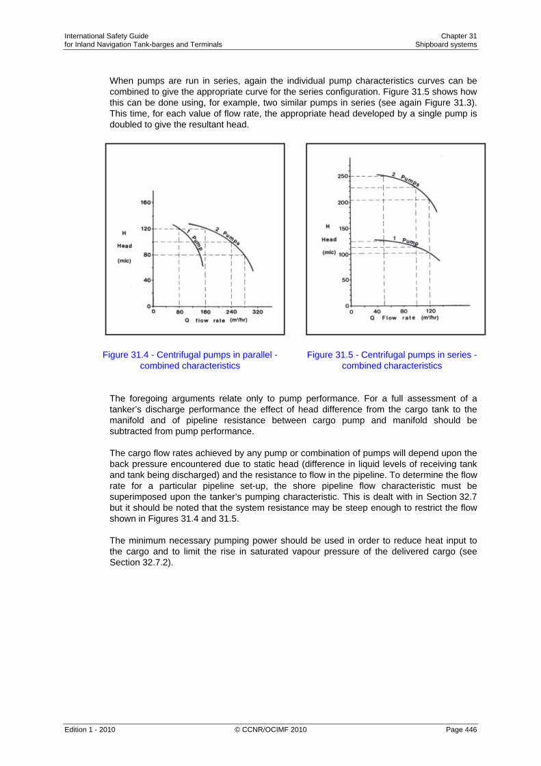
When pumps are run in series, again the individual pump characteristics curves can be combined to give the appropriate curve for the series configuration. Figure 31.5 shows how this can be done using, for example, two similar pumps in series (see again Figure 31.3). This time, for each value of flow rate, the appropriate head developed by a single pump is doubled to give the resultant head.
Figure 31.4 - Centrifugal pumps in parallel - Figure 31.5 - Centrifugal pumps in series - combined characteristics combined characteristics
The foregoing arguments relate only to pump performance. For a full assessment of a tanker’s discharge performance the effect of head difference from the cargo tank to the manifold and of pipeline resistance between cargo pump and manifold should be subtracted from pump performance. The cargo flow rates achieved by any pump or combination of pumps will depend upon the back pressure encountered due to static head (difference in liquid levels of receiving tank and tank being discharged) and the resistance to flow in the pipeline. To determine the flow rate for a particular pipeline set-up, the shore pipeline flow characteristic must be superimposed upon the tanker’s pumping characteristic. This is dealt with in Section 32.7 but it should be noted that the system resistance may be steep enough to restrict the flow shown in Figures 31.4 and 31.5. The minimum necessary pumping power should be used in order to reduce heat input to the cargo and to limit the rise in saturated vapour pressure of the delivered cargo (see Section 32.7.2).

International Safety Guide Chapter 31 for Inland Navigation Tank-barges and Terminals Shipboard systems
Edition 1 - 2010 © CCNR/OCIMF 2010 Page 447
Deepwell pumps Deepwell pumps are the most common type of cargo pump for Gas carriers. Figure 31.6 shows a typical deepwell pump assembly. The pump is driven electrically or hydraulically (through a sealing arrangement) by a motor which is mounted outside the tank. The drive shaft is held in carbon bearings inside the cargo discharge tube and these bearings are lubricated and cooled by the cargo flow. The centrifugal impeller is mounted at the bottom of the cargo tank and frequently comprises two or three stages together with a first stage inducer: this latter is used to minimise the NPSH requirement of the pump. Shaft sealing at the cargo tank dome consists of a double mechanical seal flushed with lubricating oil. This stops cargo leakages to atmosphere. The accurate alignment of the motor coupling, thrust bearing and mechanical oil seal is important. Furthermore, the length of the drive shaft can be a problem and the longer it becomes the more support is needed. Accordingly, it is often found that the largest types of tankers are fitted with submerged pumps. Submerged motor pumps Submerged motor pumps are installed at the bottom of cargo tanks and enable very low pump-down levels to be achieved. They are fitted on some of the larger gas carriers. The pump and electric motor are integrally mounted on the same shaft so eliminating the need for a mechanical seal or coupling. Power is supplied to the motor through specially sheathed cables. Electrical cabling is passed through a hazardous area junction box in the tank dome and then, by flexible cables to the motor terminals. The older mineral insulated copper sheathed cable used inside cargo tanks has been superseded in modern tankers by flexible stainless steel armoured insulated power cables. These pumps are cooled and lubricated by cargo flow and are, therefore, prone to damage due to loss of flow. Accordingly, the pump is protected from dry running by safety devices such as an under-current relay, a low discharge pressure switch, or a low tank level switch. Figure 31.7 shows a typical submerged pump/motor assembly for a gas carrier. Submerged pumps need to be designed for the particular grades of cargo found on the ship’s Certificate of Fitness. For example, contrary to the hydrocarbon gases, ammonia is an electric conductor and can also be a particularly corrosive cargo for some materials such as copper wires and electrical insulation. Pump design must take this into account. To preserve the electric motor, pumps used for ammonia have the electric stator enclosed in a ‘can’. Booster pumps Booster pumps are usually of the centrifugal type. They may be vertically or horizontally mounted on deck in the appropriate discharge line. In these positions, they will be driven by an increased safety (E Exe) (see Section 31.8) electric motor. Alternatively, they may be in the cargo compressor room. When fitted in the compressor room, they are driven through a gas-tight bulkhead by an electric motor installed in the electric motor room. Figures 31.8 and 31.9 show examples of these types of pump. The particular pumps shown are fitted with double mechanical seals. The seal flushing system should be well maintained to ensure continuing reliability.

International Safety Guide Chapter 31 for Inland Navigation Tank-barges and Terminals Shipboard systems
Edition 1 - 2010 © CCNR/OCIMF 2010 Page 448
Figure 31.6 - Typical deepwell pump

International Safety Guide Chapter 31 for Inland Navigation Tank-barges and Terminals Shipboard systems
Edition 1 - 2010 © CCNR/OCIMF 2010 Page 449
Figure 31.7 - Submerged motor pump for Gases

International Safety Guide Chapter 31 for Inland Navigation Tank-barges and Terminals Shipboard systems
Edition 1 - 2010 © CCNR/OCIMF 2010 Page 450
Figure 31.8 - Vertical booster pump
Figure 31.9 Horizontal booster pump

International Safety Guide Chapter 31 for Inland Navigation Tank-barges and Terminals Shipboard systems
Edition 1 - 2010 © CCNR/OCIMF 2010 Page 451
Ice prevention at cargo pumps The formation of ice or hydrates (see Section 27.9) may occur in tankers carrying refrigerated or semi-pressurised LPG. Furthermore, hydrates may be transferred from the terminal during loading operations. Hydrates from the shore can be removed by cargo filters in the terminal loading lines. Hydrate formations may enter cargo pumps, block lubricating passages, unbalance impellers and seize bearings. To prevent such damage it is common practice to inject a small quantity of freezing-point depressant into the cargo pump, especially submerged pumps, to facilitate de-icing. Because of the danger of methanol contamination to certain LPG cargoes, injection of this product should not normally be allowed without cargo receivers’ agreement. When deepwell pumps are not in operation, it is recommended that manual rotation of the shafts be carried out during cool-down and loading to prevent freezing of the impellers.
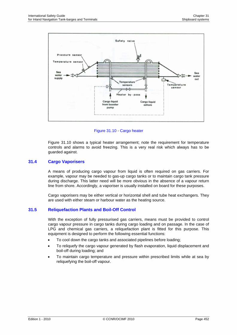
31.3 Cargo Heaters When discharging refrigerated cargoes into pressurised shore storage, it is usually necessary to heat the cargo so as to avoid low-temperature embrittlement of the shore tanks and pipelines. Cargo heaters are normally of the conventional horizontal shell and tube type exchanger. Most often, they are mounted in the open air on the tanker’s deck. Harbour water is commonly used as the heating medium and this passes inside the tubes with the cargo passing around the tubes. The heaters are typically designed to raise the temperature of fully refrigerated propane from -45°C to –5°C; however, it should be noted that the cargo flow rate at which this temperature rise may be achieved can be significantly reduced in cold water areas. Under such circumstances only very slow discharge rates may be possible and when water temperatures fall below 5°C it becomes increasingly difficult to use water as a heating medium.
International Safety Guide Chapter 31 for Inland Navigation Tank-barges and Terminals Shipboard systems
Edition 1 - 2010 © CCNR/OCIMF 2010 Page 452
Figure 31.10 - Cargo heater
Figure 31.10 shows a typical heater arrangement; note the requirement for temperature controls and alarms to avoid freezing. This is a very real risk which always has to be guarded against.
31.4 Cargo Vaporisers A means of producing cargo vapour from liquid is often required on gas carriers. For example, vapour may be needed to gas-up cargo tanks or to maintain cargo tank pressure during discharge. This latter need will be more obvious in the absence of a vapour return line from shore. Accordingly, a vaporiser is usually installed on board for these purposes. Cargo vaporisers may be either vertical or horizontal shell and tube heat exchangers. They are used with either steam or harbour water as the heating source.
31.5 Reliquefaction Plants and Boil-Off Control With the exception of fully pressurised gas carriers, means must be provided to control cargo vapour pressure in cargo tanks during cargo loading and on passage. In the case of LPG and chemical gas carriers, a reliquefaction plant is fitted for this purpose. This equipment is designed to perform the following essential functions: • To cool down the cargo tanks and associated pipelines before loading; • To reliquefy the cargo vapour generated by flash evaporation, liquid displacement and
boil-off during loading; and • To maintain cargo temperature and pressure within prescribed limits while at sea by
reliquefying the boil-off vapour.

International Safety Guide Chapter 31 for Inland Navigation Tank-barges and Terminals Shipboard systems
Edition 1 - 2010 © CCNR/OCIMF 2010 Page 453
There are two main types of reliquefaction plant and these are described in the following sections.
31.5.1 Indirect Cycles
Indirect cycle is descriptive of a system where an external refrigeration plant is employed to condense the cargo vapour without it being compressed. This cycle is relatively uncommon as its use is limited to a small numbers of cargoes. It requires, for efficiency, a very cold refrigerant and large surfaces for heat exchange.
This type of reliquefaction plant is, however, required by the Gas Codes when carrying any of the following cargoes • Chlorine. • Ethylene oxide. • Ethylene oxide — propylene oxide mix. • Propylene oxide.
Figure 31.10(a) - Examples of indirect cooling cycles Reference to Table 27.5 shows that with respect to propylene oxide it is unlikely, but dependent on ambient conditions, that refrigeration will be required on voyage. Two indirect cycle systems are shown diagrammatically in Figure 31.10(a).
31.5.2 Direct Cycles Direct cycle is descriptive of a system where the boil-off is compressed, condensed and returned to the tank. This is the most common system, but may not be employed for certain gases. There are three main types of direct cycle reliquefaction plant and these are described in the following sections.

International Safety Guide Chapter 31 for Inland Navigation Tank-barges and Terminals Shipboard systems
Edition 1 - 2010 © CCNR/OCIMF 2010 Page 454
Single-stage direct cycle The single-stage direct cycle system is particularly suited to the semi-pressurised carrier. A simplified diagram of single-compression reliquefaction is shown in Figures 31.11(a) and (b). This cycle is suitable where suction pressures are relatively high, as in the carriage of semi-pressurised products. Boil-off vapours from the cargo tank are drawn off by the compressor — (a) in the diagrams. Compression increases the pressure and temperature of the vapour — to (b) in the diagrams. The high temperature allows it to be condensed against sea water in the condenser — at (c) in the diagrams. The condensed liquid is then flashed back to the tank via a float controlled expansion valve — at (d) in the diagrams. The liquid/vapour mixture being returned the cargo tank may be either distributed by a spray rail at the top of the cargo tank or taken to the bottom of the tank to discourage re-vaporisation. The spray rail is normally used when the tank is empty and bottom discharge when the tank is full (see also Section 27.21 and Figure 27.18).
Figure 31.11(a) - Single-stage direct reliquefaction cycle

International Safety Guide Chapter 31 for Inland Navigation Tank-barges and Terminals Shipboard systems
Edition 1 - 2010 © CCNR/OCIMF 2010 Page 455
Figure 31.11(b) - Mollier diagram — single-stage direct reliquefaction cycle Two-stage direct cycle Although two-stage direct cycle equipment is relatively uncommon, it is used for those liquefied gas carriers handling a wide range of products. For grades such as butadiene and vinyl chloride its fitting is essential. A simplified diagram showing two-stage reliquefaction is given in Figures 31.12(a) and (b). The two-stage cycle with inter-stage cooling is used where suction pressures are low and, as a result, compression ratios high (assuming harbour water condensing) compared to the single-stage cycle. Two-stage compression (with inter-stage cooling) is necessary to limit the compressor discharge temperature which increases significantly with the higher compression ratio. This is particularly important for cargoes such as butadiene and vinyl chloride (see also Section 32.6).

International Safety Guide Chapter 31 for Inland Navigation Tank-barges and Terminals Shipboard systems
Edition 1 - 2010 © CCNR/OCIMF 2010 Page 456
Figure 31.12(a) - Two-stage direct reliquefaction cycle with inter-stage cooling
Figure 31.12(b) - Mollier diagram — two-stage direct reliquefaction cycle The vapour from the first stage discharge — (b) in the diagrams — is taken to an interstage cooler where its superheat is reduced — (c) in the diagrams. The cooling medium is cargo liquid flashed down to intercooler pressure from the harbour water-cooled condenser. The remaining parts of the cycle are similar to the single-stage cycle.

International Safety Guide Chapter 31 for Inland Navigation Tank-barges and Terminals Shipboard systems
Edition 1 - 2010 © CCNR/OCIMF 2010 Page 457
Cascade direct cycle The cascade cycle is used for fully refrigerated cargoes where a special refrigerant such as R22* (see below) is used to obtain the lower carriage temperatures. Furthermore in these systems, refrigeration plant capacities are not so affected by sea water temperature changes compared with other reliquefaction cycles. For the carriage of ethylene this type of equipment is essential.
Figure 31.13 - Simplified cascade reliquefaction cycle The cascade system uses a refrigerant such as R22 to condense cargo vapours; a simplified diagram for this system is shown in Figure 31.13. The single-stage compression of cargo vapour is identical to the single-stage direct cycle, but the cargo condenser is cooled using R22 instead of harbour water. The cargo, in condensing, evaporates the liquid R22 and the R22 vapour is then taken through a conventional R22 closed refrigeration cycle, condensing against harbour water — hence the term cascade. * Refrigerant gas – R22 As appropriate the indirect and direct cascade reliquefaction systems discussed in this Guide are assumed to use the refrigerant monochlorodifluoromethane which is more normally referred to by its refrigerant number R22. This material is a halogenated chloro fluoro carbon (HCFC). It is well suited for use in reliquefaction plants, particularly in reciprocating type compressors. This refrigerant is not specifically listed in the Montreal protocol to be phased out but a separate agreement, indicating that its eventual phasing out by the year 2015 is desirable, has been reached by all signatories to the Montreal protocol. Research into suitable replacements is under way with major chemical companies involved.

International Safety Guide Chapter 31 for Inland Navigation Tank-barges and Terminals Shipboard systems
Edition 1 - 2010 © CCNR/OCIMF 2010 Page 458
R22 has a very low toxicity; however, in the presence of a naked flame it breaks down into a toxic gas which has a very strong smell. As per the Montreal Protocol, R22 will eventually be phased out in the not too distant future. As per EU protocol 2037/2000, HCFC will be banned from January 2010.
31.6 Cargo Compressors and Associated Equipment The compressor is the heart of the reliquefaction plant. As far as LPG tankers are concerned there are two main types of compressor: these are the reciprocating type and the screw type.
31.6.1 Reciprocating Compressors Older compressors were sometimes not of the oil-free type. This attracted the problems discussed in Sections 27.10 and 32.6.1 because many liquefied gases can adversely affect the quality of the lubricating oil used in the machines. In using these older compressors, very careful control is required. In particular, sump heating systems are often fitted in order to evaporate any dissolved gases. In addition, the changing of lubricating oil between cargoes is usually necessary. Full data on the operation of these compressors should be available from manufacturers’ handbooks. For these reasons, the vast majority of reciprocating cargo compressors now found on board gas carriers are of the so-called oil-free type.
International Safety Guide Chapter 31 for Inland Navigation Tank-barges and Terminals Shipboard systems
Edition 1 - 2010 © CCNR/OCIMF 2010 Page 459
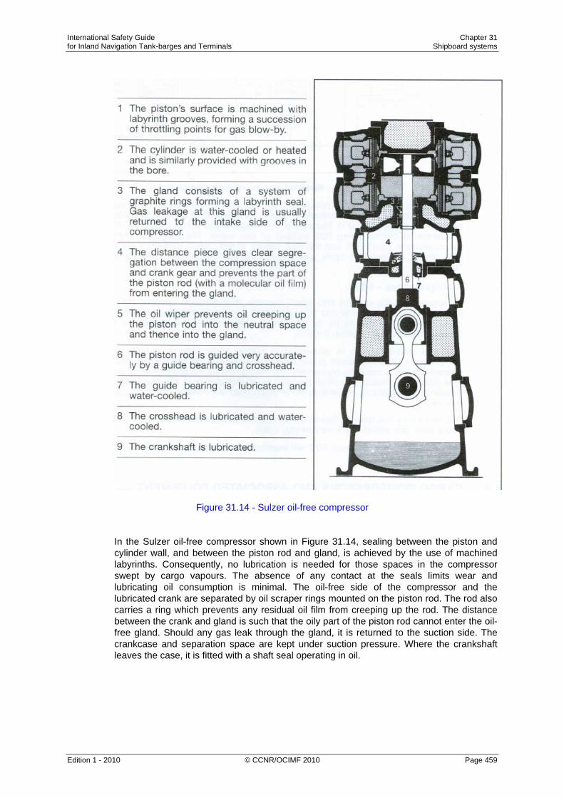
Figure 31.14 - Sulzer oil-free compressor In the Sulzer oil-free compressor shown in Figure 31.14, sealing between the piston and cylinder wall, and between the piston rod and gland, is achieved by the use of machined labyrinths. Consequently, no lubrication is needed for those spaces in the compressor swept by cargo vapours. The absence of any contact at the seals limits wear and lubricating oil consumption is minimal. The oil-free side of the compressor and the lubricated crank are separated by oil scraper rings mounted on the piston rod. The rod also carries a ring which prevents any residual oil film from creeping up the rod. The distance between the crank and gland is such that the oily part of the piston rod cannot enter the oil-free gland. Should any gas leak through the gland, it is returned to the suction side. The crankcase and separation space are kept under suction pressure. Where the crankshaft leaves the case, it is fitted with a shaft seal operating in oil.
International Safety Guide Chapter 31 for Inland Navigation Tank-barges and Terminals Shipboard systems
Edition 1 - 2010 © CCNR/OCIMF 2010 Page 460
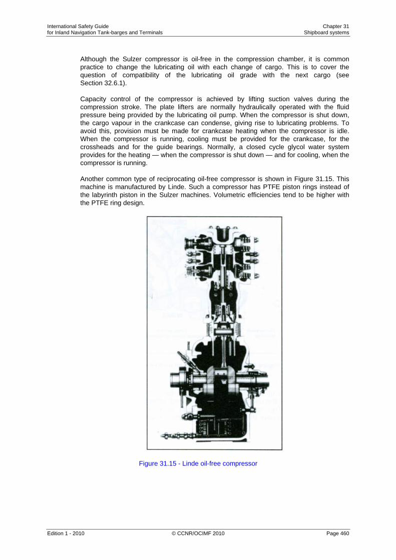
Although the Sulzer compressor is oil-free in the compression chamber, it is common practice to change the lubricating oil with each change of cargo. This is to cover the question of compatibility of the lubricating oil grade with the next cargo (see Section 32.6.1). Capacity control of the compressor is achieved by lifting suction valves during the compression stroke. The plate lifters are normally hydraulically operated with the fluid pressure being provided by the lubricating oil pump. When the compressor is shut down, the cargo vapour in the crankcase can condense, giving rise to lubricating problems. To avoid this, provision must be made for crankcase heating when the compressor is idle. When the compressor is running, cooling must be provided for the crankcase, for the crossheads and for the guide bearings. Normally, a closed cycle glycol water system provides for the heating — when the compressor is shut down — and for cooling, when the compressor is running. Another common type of reciprocating oil-free compressor is shown in Figure 31.15. This machine is manufactured by Linde. Such a compressor has PTFE piston rings instead of the labyrinth piston in the Sulzer machines. Volumetric efficiencies tend to be higher with the PTFE ring design.
Figure 31.15 - Linde oil-free compressor

International Safety Guide Chapter 31 for Inland Navigation Tank-barges and Terminals Shipboard systems
Edition 1 - 2010 © CCNR/OCIMF 2010 Page 461
31.6.2 Screw Compressors
Screw compressors for use with liquefied gas cargoes can be either dry oil-free or oil-flooded machines. In the dry machines, the screw rotors do not make physical contact but are held in-mesh and driven by external gearing. Due to leakage through the clearances between the rotors, high speeds are necessary to maintain good efficiency (typically 12,000 rpm). Figure 31.16 is a diagram of a typical rotor set with the common combination of four and six lobes. The lobes inter-mesh and gas is compressed in the chambers numbered 1, 2, 3, in the diagram which are reduced in size as the rotors turn. The compressor casing carries the suction and discharge ports. The oil-flooded machine relies on oil injection into the rotors and this eliminates the need for timing gears. Drive power is transmitted from one rotor to the other by the injected oil. This also acts as a lubricant and coolant. Because the rotors are sealed with oil, gas leakage is much less and, therefore, oil-flooded machines can run at lower speeds (3,000 rpm). An oil separator on the discharge side of the machine removes oil from the compressed gas.
Figure 31.16 - Typical rotor for an oil-free screw compressor Capacity control of screw compressors can be achieved in a number of ways. The most common is the use of a sliding valve which effectively reduces the working length of the rotors. This is more efficient than suction throttling. Screw compressors consume more power than reciprocating compressors.

International Safety Guide Chapter 31 for Inland Navigation Tank-barges and Terminals Shipboard systems
Edition 1 - 2010 © CCNR/OCIMF 2010 Page 462
31.6.3 Compressor Suction Liquid Separator
It is necessary to protect cargo vapour compressors against the possibility of liquid being drawn in. Such a situation can seriously damage compressors since liquid is incompressible. It is normal practice, therefore, to install a liquid separator on the compressor suction line coming in from the cargo tanks. The purpose of this vessel is to reduce vapour velocity and, as a result, to allow any entrained liquid to be easily removed from the vapour stream. In case of over-filling, the separator is fitted with high-level sensors which set off an alarm and trip the compressor.
31.6.4 Purge Gas Condenser Many reliquefaction plants are fitted with a heat exchanger mounted above the cargo condenser. These units are of the shell and tube types. The purpose of this heat exchanger is to condense any cargo vapours which remain mixed with incondensable gases (such as nitrogen). These cargo vapours may have failed to condense in the main condenser. For example, commercial propane which may have 2 per cent ethane in the liquid will have perhaps 14 per cent ethane in the vapour; ethane being the more volatile component. On a semi-pressurised LPG carrier, the presence of ethane can cause difficulties in a conventional sea water-cooled condenser.
Figure 31.17 - Typical purge gas condenser system

International Safety Guide Chapter 31 for Inland Navigation Tank-barges and Terminals Shipboard systems
Edition 1 - 2010 © CCNR/OCIMF 2010 Page 463
Figure 31.17 shows a typical purge gas condenser system. The uncondensed gases in the main condenser are displaced into the shell of the purge condenser. Here they are subjected to the same pressure that exists in the main condenser but to a lower condensing temperature. This is equivalent to the outlet temperature from the expansion valve, since the whole or part of this liquid passes through the tube side of the purge condenser. This lower condensing temperature allows cargo vapours to be condensed and incondensible gases are purged from the top of the purge gas condenser by a pressure control system.
31.7 Inert Gas and Nitrogen Systems As covered in Section 27.7, gas carriers use various forms of inert gas and these are listed below: • Inert gas from combustion-type generators; • Nitrogen from shipboard production systems, and • Pure nitrogen taken from the shore (either by pipeline, road tanker or barge).
31.7.1 Nitrogen Production on Tankers The most common system utilised for the production of nitrogen on tankers is an air separation process. This system works by separating air into its component gases by passing compressed air over hollow fibre membranes. The membranes divide the air into two streams — one is essentially nitrogen and the other contains oxygen, carbon dioxide plus some trace gases. This system can produce nitrogen of about 95 up to 99.8 per cent purity. The capacity of these systems depends on the number of membrane modules fitted and is dependant on inlet air pressure, temperature and the required nitrogen purity. Figure 31.18 shows one such system.
Figure 31.18 - The membrane system for producing nitrogen
International Safety Guide Chapter 31 for Inland Navigation Tank-barges and Terminals Shipboard systems
Edition 1 - 2010 © CCNR/OCIMF 2010 Page 464
31.7.2 Pure Nitrogen from the Shore
The quality of inert gas produced by shipboard systems is usually inadequate for oxygen-critical cargoes — see strict in-tank oxygen requirements in Table 27.3(b). Bearing in mind the components in the inert gas, this may create restrictions on use if tanks have been previously gas-freed for inspection; and this is often necessary when a change in grades is involved. Under these circumstances, and prior to loading, it is normal for Masters to arrange for cargo tanks to be inerted with pure nitrogen, taken from the shore. This is usually delivered by pipeline, road tanker or barge. As deliveries are mostly in liquid form, where immediate inerting is required, a nitrogen vaporiser is needed.
31.8 Electrical Equipment in Gas Dangerous Spaces A common definition of area safety classification for electrical equipment is as follows: Zone 0: An area with a flammable mixture continuously present. Zone 1: An area where flammable mixtures are likely during normal operations. Zone 2: An area where flammable mixtures are unlikely during normal operations. Electrical installations on gas carriers are subject to the requirements of the classification society and the Gas Codes. Zones and spaces on tankers are classified as either gas-safe or gas-dangerous, depending on the risk of cargo vapour being present. For example, accommodation and machinery spaces are gas-safe, while compressor rooms, cargo tank areas and holds are gas-dangerous. In gas-dangerous spaces, only electrical equipment of an approved standard may be used; this applies to both fixed and portable electrical equipment. There are several types of electrical equipment certified as being safe for use on gas carriers and these are described in the following sections. Intrinsically safe equipment Intrinsically safe equipment can be defined as an electrical circuit in which a spark or thermal effect (under normal operation or specified fault conditions) is incapable of causing the ignition of a given explosive mixture. Limitation of such energy may be achieved by placing a barrier, as shown in Figure 31.19, in the electrical supply. This must be positioned in a safe area. Zener barriers are frequently used for this purpose and, in the circuit shown, the voltage is limited by the Zener diodes so that the maximum current flow to the hazardous area is restricted by the resistors. The uses of such intrinsically safe systems are normally limited to instrumentation and control circuitry in hazardous areas. Because of the very low energy levels to which they are restricted, intrinsically safe systems cannot be used in high-power circuits.

International Safety Guide Chapter 31 for Inland Navigation Tank-barges and Terminals Shipboard systems
Edition 1 - 2010 © CCNR/OCIMF 2010 Page 465
Figure 31.19 - Intrinsic safety using Zener barriers Flameproof equipment A flameproof enclosure is one which can withstand the pressure developed during an internal ignition of a flammable mixture. Furthermore, the design is such that any flames, occurring within the enclosure, are cooled to below ignition temperatures before reaching the surrounding atmosphere. Therefore, the gap through which hot gases are allowed to escape is critical and great care must be taken in assembly and maintenance of flameproof equipment to ensure that these gaps are well maintained. No bolts must be omitted or tightened incorrectly, while the gap must not be reduced by painting, corrosion or other obstructions. Pressurised or purged equipment The pressurisation or purging of equipment is a technique used to ensure that an enclosure remains gas-free. In the case of pressurisation, an over-pressure of about 0.5 bar, relative to the surrounding atmosphere, must be maintained. In the case of a purged enclosure, a continuous supply of purging gas must be provided to the enclosure. Air or inert gas can be used. Increased safety equipment The use of Increased Safety Equipment is appropriate for electrically powered light fittings and motors. This equipment has a greater than normal separation between electrical conductors and between electric terminals. Starters are designed to minimise both arcing at contactors and to limit the temperature of components. Increased safety motors, with flameproof enclosures, are frequently used on deck on gas carriers. Here they may be found driving deepwell pumps or booster pumps. In such cases they must be protected by a suitable weatherproof covering.

International Safety Guide Chapter 31 for Inland Navigation Tank-barges and Terminals Shipboard systems
Edition 1 - 2010 © CCNR/OCIMF 2010 Page 466
31.9 Instrumentation
Instrumentation is an important part of gas tanker equipment and is required for the measurement of cargo level, pressure and temperature. It is also used for gas detection. Instrumentation must be carefully selected and well maintained.
31.9.1 Liquid Level Instrumentation The applicable Gas Codes and classification society rules normally require every cargo tank to be fitted with at least one liquid level gauge. Specific types of gauging system are required for certain cargoes. Classification for gauging systems is as follows: • Indirect systems — these may be either weighing methods or flow meters. • Closed devices which do not penetrate the cargo tank — here ultrasonic devices or
radio isotope sources may be used. • Closed devices which penetrate the cargo tank — such as float gauges and radar type
gauges. Float gauges
Figure 31.20 - Float level gauge

International Safety Guide Chapter 31 for Inland Navigation Tank-barges and Terminals Shipboard systems
Edition 1 - 2010 © CCNR/OCIMF 2010 Page 467
The float gauge is widely used on all gas carriers. It consists of a float attached by a tape to an indicating device which can be arranged for local and remote readout. Figure 31.20 shows a typical float gauge installed in a tubular well. Alternatively guide wires may be fitted. Float gauges have gate valves for isolation so that the float can be serviced in a safe atmosphere. The float must be lifted from the liquid level when not in use; if left down, liquid sloshing especially in rough conditions, will damage the tape-tensioning device. Float gauges are normally placed in a tank sump or reach to a minimum distance to the tank bottom Radar gauges Another type of tank gauging equipment is that designed to operate on the principle of radar. Such equipment works at very high frequencies — approximately 11 gigahertz (11 x 109). Radar type liquid level gauges have now been specially developed for liquefied gases and their usage on gas tankers. The equipment provides measurements adequate to meet industry requirements. The above devices are classed as closed devices. This means that, when in use, no cargo liquids or vapours are released to the atmosphere during level measurement
31.9.2 Level Alarm and Automatic Shut-down Systems Every cargo tank should be fitted with an independent high level sensor giving audible and visual alarms. The float, capacitance or ultrasonic sensors may be used for this purpose. The high-high-level alarm — or other independent sensor — is required to automatically stop the flow of cargo to the tank. During cargo loading, there is a danger of generating a significant surge pressure if the valve stopping the flow closes too quickly against a high loading rate. (For further information on surge pressure see Sections 31.1.3 and 16.10).
31.9.3 Pressure and Temperature Monitoring The applicable Gas Codes should call for pressure monitoring throughout the cargo system. Appropriate positions include cargo tanks, pump and compressor discharge lines, liquid crossovers and vapour crossovers. In addition, pressure switches are fitted to various systems to protect personnel and equipment by operating alarms and shut-down systems. It is recommended that more than one thermometer be fitted to the cargo tanks to assist with monitoring to prevent undue thermal stresses. Tanker’s staff should be aware of the lowest temperatures to which the cargo tanks can be exposed and these values should be marked on the temperature gauges — especially those at the cargo manifold.

International Safety Guide Chapter 31 for Inland Navigation Tank-barges and Terminals Shipboard systems
Edition 1 - 2010 © CCNR/OCIMF 2010 Page 468