CHAPTER 3 SSPSI ANALYTICAL METHODS: THEORY, CODE, AND … · A pseudo-static method for pile...
76
75 CHAPTER 3 SSPSI ANALYTICAL METHODS: THEORY, CODE, AND PRACTICE 3.1 Analytical Methods The development of analytical methods for SSPSI has principally been driven by the demands of two sectors, offshore oil production activities, and to a lesser extent, the nuclear power industry. For offshore applications, where cyclic wave loading applies lateral loads to pile-supported marine structures, a limited series of field and model tests has established the empirically-based and widely accepted “p-y” method of laterally loaded pile analysis. This static loading analysis method has been modified and extended to cyclic loading conditions, and is also routinely applied to dynamic or earthquake loading cases. At the same time, dynamic soil-pile analysis methods have been developed for the idealization of piles embedded in a visco-elastic medium; these techniques have also found their way into practice. They are more theoretically grounded than the p-y method, and along with the finite element method, are an outgrowth of the considerable effort in the 1960’s and 1970’s to study the soil-structure interaction problem of partially embedded nuclear power plants. However, these methods generally do not allow for the adequate characterization of localized yielding at the soil-pile interface, and are therefore better- suited to relatively low levels of seismic loading. In addition to these classes of analysis, four levels of progressively “complete” SSPSI analyses can be described. The basic level consists of a single pile kinematic seismic response analysis, normally incorporating nonlinear response and performed as a
Transcript of CHAPTER 3 SSPSI ANALYTICAL METHODS: THEORY, CODE, AND … · A pseudo-static method for pile...

75
CHAPTER 3 SSPSI ANALYTICAL METHODS:
THEORY, CODE, AND PRACTICE
3.1 Analytical Methods
The development of analytical methods for SSPSI has principally been driven by
the demands of two sectors, offshore oil production activities, and to a lesser extent, the
nuclear power industry. For offshore applications, where cyclic wave loading applies
lateral loads to pile-supported marine structures, a limited series of field and model tests
has established the empirically-based and widely accepted “p-y” method of laterally loaded
pile analysis. This static loading analysis method has been modified and extended to cyclic
loading conditions, and is also routinely applied to dynamic or earthquake loading cases.
At the same time, dynamic soil-pile analysis methods have been developed for the
idealization of piles embedded in a visco-elastic medium; these techniques have also found
their way into practice. They are more theoretically grounded than the p-y method, and
along with the finite element method, are an outgrowth of the considerable effort in the
1960’s and 1970’s to study the soil-structure interaction problem of partially embedded
nuclear power plants. However, these methods generally do not allow for the adequate
characterization of localized yielding at the soil-pile interface, and are therefore better-
suited to relatively low levels of seismic loading.
In addition to these classes of analysis, four levels of progressively “complete”
SSPSI analyses can be described. The basic level consists of a single pile kinematic
seismic response analysis, normally incorporating nonlinear response and performed as a

76
pile integrity evaluation. A pseudo-static method for pile integrity evaluation consists of
transforming the horizontal profile of soil displacement (derived from a free-field site
response analysis) to a curvature profile, and comparing peak values to allowable pile
curvatures (see Figure 3.1). This method assumes piles perfectly follow the soil, and that
no inertial interaction takes place. Alternatively, a displacement time history may be
applied to nodal points along the pile in a dynamic pile integrity analysis. In a second level
of analysis, pile head stiffness or impedance functions may be condensed from linear or
nonlinear soil-pile analyses and assembled into a pile group stiffness matrix for use in a
global response analysis (Figure 3.2). Secant stiffness values at design level deformations
are normally proscribed from nonlinear soil-pile response analyses (Figure 3.3). Third,
both inertial and kinematic interaction may be evaluated from a substructuring type
analysis to determine pile head impedance and foundation level input motions (Figure 3.4).
Finally, a fully coupled SSPSI analysis may be carried out to ascertain the complete system
response.
Figure 3.1 - Pile Curvature Profile Derived from Site Response Analysis(after Margasson and Holloway, 1977)

77
Figure 3.2 - Flexible Pile Stiffness Matrix (after Kriger and Wright, 1980)
Figure 3.3 - Selection of Secant Stiffness Value at Design Level Displacement fromNonlinear Soil-Pile Force-Displacement Curve (after Kriger and Wright, 1980)

78
Figure 3.4 - Substructuring Concept: a) Definition of Problem; b) Decomposition intoInertial and Kinematic Interaction Problems; c) Two-step Analysis of Inertial Interaction
(after Gazetas, 1984)

79
It is instructive to recognize that each class of analysis may be applied to multiple
levels of analysis. For example, a beam-on-Winkler-foundation analysis may be conducted
as a pile integrity evaluation or to compute pile head stiffness terms. An elastic continuum
analysis can be utilized to determine pile head impedance or applied in a substructuring
fashion. Finite element methods have been employed to develop other classes of analysis
as well as to perform complete SSPSI analyses.
Static, cyclic, and dynamic loading are all considered in the SSPSI problem.
Figure 3.5 depicts idealized soil-pile load-displacement diagrams for each of these various
modes of loading. Simplified methods for determining static pile head stiffness are
routinely used for dynamic response analyses, as it has been determined that pile head
static stiffness is roughly equivalent to dynamic stiffness in the seismic frequency range of
interest. Several caveats must be made for this simplifying assumption: 1) unlike stiffness,
damping is frequency dependent over the range of interest, and it is therefore common
practice to select impedance function values at the site and/or structural resonant
frequencies; 2) static stiffness terms should be degraded to account for the effects of cyclic
loading; 3) dynamic axial stiffness terms are not as well approximated by static stiffness as
for lateral response; and 4) dynamic pile group efficiencies and load distribution are
significantly different from static values. It is important to recognize that both lateral and
axial stiffness terms are vital components of pile group impedance functions, as structural
inertial response may induce a foundation rocking mode and mobilize axial pile resistance.
Finally, pile group effects must be accounted for in the SSPSI analyses, and are more fully
described in section 3.1.5. They may be implicit in a substructuring or complete analysis,

80
but have to be separately accounted for with interaction factors when assembling a pile
group impedance matrix from individual pile terms.
Figure 3.5 - Soil-Pile Load Displacement Diagrams for Various Modes of Loading(after Mosikeeran, 1990)
Distinctions are commonly made between fixed head and free head (“pinned”
connection) piles, and “rigid” and “flexible” pile behavior (see Figure 3.6) based on
relative soil-pile stiffness. Flexible pile behavior is an underlying assumption of the beam-
on-Winkler-foundation analysis and is often intrinsic to elastic continuum analyses as a
plane strain assumption. Rigid pile behavior requires that the cross-coupling stiffness
terms associated with the additional modes of shaft resistance be accounted for in the
analysis method (Figure 3.7). Various researchers have proposed criteria for rigid and
flexible behavior, and they are summarized in Table 3-1.

81
Table 3-1 Criteria for Pile Rigidity (after Kulhawy and Chen, 1995)
Source Criterion forRigid Behavior
Criterion forFlexible Behavior
Note
Broms (1964a) βrD < 1.5 βrD > 1.5 aPoulos & Davis (1980) Kr > 10-2 Kr < 10-5 bBierschwale et al. (1981) D/B < 6 D/B > 6 cDobry et al. (1982) SH < 5 SH > 5 dDavies & Budhu (1986) D < 1.5 B K0.36 D > 1.5 B K0.36 eBudhu & Davies (1987) D < 1.3 B K0.222 D > 1.3 B K0.222 fCarter & Kulhawy (1988) D/B < 0.05 (Ep/G*)0.5 D/B > (Ep/G*)2/7 gPoulos & Hull (1989) D < Dp/3 D > Dp hNote: B = pile diameter, D = pile depth, Ep = pile elastic modulus, Ip = pile moment of inertia, Es = soil elastic modulus, νs = soil Poisson’s ratio, Gs = soil shear modulus a - βr = (khB/4EpIp)
0.25; kh = coefficient of subgrade reaction b - Kr = (EpIp/EsD
4) = flexibility factor c - in some cases, may be rigid for D/B < 10 d - SH = (D/B)/(Ep/Es)
0.25 = flexibility factor
e - K = (Ep/Es) = stiffness ratio; for constant soil modulus with depth f - K = (Ep/mB); m is Es rate of increase; for linear variation of soil modulus with depth g - G* = Gs(1+3νs/4) = modified soil shear modulus h - Dp = 4.44(EpIp/Es)
0.25 = critical pile depth
Figure 3.6 - Rigid Versus FlexiblePile Behavior(after Kulhawy and Chen, 1995)
Figure 3.7 - Rigid Pile Lateral LoadingResistance Components (after Kulhawyand Chen, 1995)

82
The following sections will present a brief overview of four types of SSPSI
analyses; these generally fall into the discrete and continuum classes of models. For a
more complete review refer to Novak (1991), Gohl (1993), Pender (1993), or Gazetas
and Mylonakis (1998).
3.1.1 Beam-on-Elastic Foundation
Hetenyi (1946) originally presented beam-on-elastic-foundation solutions (also
known as the subgrade reaction method) in the form of the governing fourth-order
differential equation:
pxdydEI =4
4
(3.1)
with p = -Esy and where E and I are the pile modulus of elasticity and moment of inertia, y
is the pile deflection, x is the depth below the soil surface, Es is the modulus of subgrade
reaction, and p is the reaction of soil on the pile. As is the case with the elastic continuum
method, analytical solutions are not available for arbitrary distributions of soil or pile
stiffness. This method has mainly been applied to static lateral pile loading problems, and
is therefore used for the determination of pile head stiffness terms in SSPSI analyses.
Matlock and Reese (1960) presented a generalized iterative solution method for
rigid and flexible laterally loaded piles embedded in soils with two forms of varying
modulus with depth. Davisson and Gill (1963) investigated the case of a laterally loaded
pile embedded in a layered soil system with a constant (but different) modulus of subgrade
reaction in each layer. They concluded that the near surface modulus was the controlling
factor for the pile response, and that soil investigations and characterization should be

83
focused in this zone. In classic companion papers, Broms (1964a, b) described a method
for analyzing lateral pile response in cohesive and cohesionless soils. His method for
computing ground surface deflections of rigid and flexible fixed and free head piles was
based on a modulus of subgrade reaction using values suggested by Terzaghi (1955). For
undrained loading, he designated that a constant subgrade modulus be used with a value of
9 Su for the ultimate lateral soil resistance. For drained loading cases, a subgrade modulus
linearly increasing with depth was specified and a Rankine earth pressure-based method
was used for computing an ultimate resistance assumed equal to 3KpDpσ’v.
Jamilokowski and Garassino (1977) provided a state-of-the-art discussion on soil
modulus and ultimate soil resistance for laterally loaded piles. Randolph and Houlsby
(1984) used classical plasticity theory to derive lower and upper bound values of the
limiting pressure on an undrained laterally loaded pile that ranged from approximately 9 to
12 Su as a function of pile roughness. Hansbro (1995) revisited Brom’s computation of
drained ultimate lateral resistance, and based on results of centrifuge tests conducted by
Barton (1982) suggested that a drained ultimate lateral resistance of Kp2Dpσ’v is more
appropriate for cohesionless soils. Kulhawy and Chen (1995) applied Brom’s concepts to
drilled shafts, recognizing the components of resistance to lateral loading unique to drilled
shafts, and noted the importance of conducting appropriate laboratory tests for laterally
loaded pile and drilled shaft analysis.

84
3.1.2 Beam-on-Winkler Foundation
By accepting Winkler’s foundation assumption (1876) that each layer of soil
responds independently to adjacent layers, a beam and discrete spring system may be
adopted to model pile lateral loading. Although this assumption ignores the shear transfer
between layers of soil, it has proven to be a popular and effective method for static and
dynamic lateral pile response analyses. In this method, the soil-pile contact is discretized
to a number of points where combinations of springs and dashpots represent the soil-pile
stiffness and damping at each particular layer. These soil-pile springs may be linear elastic
or nonlinear; p-y curves typically used to model nonlinear soil-pile stiffness have been
empirically derived from field tests, and have the advantage of implicitly including pile
installation effects on the surrounding soil, unlike other methods. In advanced
applications, capabilities for soil-pile gapping, cyclic degradation, and rate dependency are
also provided. A singular disadvantage of a beam-on-Winkler-foundation model is the
two-dimensional simplification of the soil-pile contact, which ignores the radial and three-
dimensional components of interaction.
For dynamic loadings, “free-field” soil acceleration time histories are usually
computed in a separate site response analysis, double integrated to displacement time
histories, and then externally applied to the soil-pile springs. The multi-step uncoupled
approach has the disadvantage of potentially introducing numerical errors in the
integration step, and artificially separates the overall soil-pile system response. Recently,
investigators have begun to develop fully-coupled analyses wherein both soil and soil-pile-
superstructure response can be simultaneously evaluated (Lok, 1999).

85
McClelland and Focht (1958) can be said to be the originators of the p-y method
of laterally loaded pile analysis. They proposed a procedure for correlating triaxial stress-
strain data to a pile load-deflection curve at discrete depths, and estimating the modulus of
subgrade reaction at each layer. Of particular interest is the ensuing discussion provided
by Peck, Matlock, and others to their paper, wherein Reese first presented his concept of a
near surface wedge (see Figure 3.8) and deep plasticity flow failure models, with an
ultimate undrained resistance of 12 Su.
Penzien et al. (1964) were some of the first researchers to present a method for
seismic pile response analysis, and focused their efforts on the problem of bridge
structures supported on long piles driven through soft clays. They constructed a multi-
degree of freedom discrete parameter system for modeling the soil medium response
initiated by seismic base excitation. This response then served as the input for the response
analysis of the discrete parameter structural system. Bilinear springs afforded nonlinear
hysteretic soil response, with parallel and series dashpots provided for soil damping and
creep, respectively, and lumped masses to contribute soil inertial effects. The conclusions
of their study regarding site response, pile curvature demands, and superstructure
ductility, all remain valid to this day.
In a series of reports to Shell Development Company, Matlock and his co-workers
conducted static and cyclic field and laboratory tests of laterally loaded piles in soft clay
(partially described in Chapter 4). He described the p-y concept as the relationship that
relates the soil resistance “p” arising from the nonuniform stress field surrounding the pile
mobilized in response to a lateral soil displacement “y” (see Figure 3.9). For a single pile,
a family of p-y curves can be described (Figure 3.10), normally stiffer with depth.

86
Figure 3.8 - Lateral Loading Near Surface Passive Wedge Geometry and Soil-Pile Forces(after Reese, 1958)
Figure 3.9 - Definition of P-Y Concept with a) Pile at Rest; b) Laterally Loaded PileMobilizing Soil Resistance (after Thompson, 1977)
Figure 3.10 - Typical Family of P-Y Curves, Progressively Stiffer with Depth(after Meyer and Reese, 1979)

87
Matlock (1970) proposed p-y curves for static and cyclic loading of piles in soft
clay which are shown in Figure 3.11a and b, with
=
yypp
cu
33.0
5.0 (3.2)
where:
p = lateral soil resistancepu = ultimate soil resistance = Np c DNp = ultimate lateral soil resistance coefficientc = soil undrained shear strengthD = pile diametery = pile deflectionyc = critical pile deflection = 2.5 εc Dεc = strain at one-half maximum deviator stress in a UU triaxial compression testx = depth below ground surfacexcr = critical depth where soil wedge failure transforms to flow failure
(a) (b)
Figure 3.11 - Characteristic Shape of P-Y Curve in Soft Clay for a) Static Loading;b) Cyclic Loading (after Matlock, 1970)
This method is codified in the API Recommended Practice (API, 1993) and is the
established criterion for laterally loaded pile analysis in soft clays in the nearly ubiquitous
computer program COM624P (Reese, 1984). Matlock also turned his attention to pile
dynamics, and issued the beam-on-dynamic-Winkler-foundation analysis program SPASM

88
8 (Matlock and Foo, 1978). In this approach, a discrete element linear elastic pile was
linked to a fully nonlinear, hysteretic, degrading soil support model with gapping capability
(Figure 3.12). The soil gapping model is shown schematically in Figure 3.13. The pile
could be extended above the mudline where element stiffnesses and restraints would be
introduced to simulate the characteristics of the superstructure. Separately computed
lateral ground displacements are used as the input excitation at the ends of the soil support
nodes. Note that nonlinear supports are specified near the pile head, and elastic supports
are presented at depth, anticipating elastic response in this zone, and providing
computational efficiency. The solution method was a time domain finite difference
procedure that iterated on soil-pile tangent stiffness to ensure compatibility with computed
deflections. A parallel array of elasto-plastic subelements provided for the nonlinear
spring stiffness (see Figure 3.14), and linear dashpots attached directly to the pile effected
radiation damping. Soil degradation was provided as a penalty method, incurred as an
element experienced a full reversal in the direction of slip, with the ultimate resistance
asymptotically approaching a user specified lower bound. In Matlock et al. (1981), a
method for simulating soil-pile response in liquefiable cohesionless soils during earthquake
shaking was presented. In this approach, the effective stress site response code DESRA II
(Lee et al., 1978) was used as input to the SPASM 8 model, with degradation of the p-y
backbone curve carried out in proportion to the excess pore pressure generation
calculated by DESRA II. Matlock and Foo (1980) also described the computer code
DRIVE 7, a model for axial loading of piles with similar features as

89
Figure 3.14 - SPASM 8 Sub-element Nonlinear Spring Model(after Matlock and Foo, 1978)
Figure 3.12 - SPASM 8 a) Soil-Pile-Superstructure Model; b) Variationin Load-Deflection Behavior versusDepth (after Matlock and Foo, 1978)
Figure 3.13 - SPASM 8 a) Soil-PileGapping Model; b) Force-DisplacementBehavior (after Matlock and Foo, 1978)

90
SPASM 8, and suitable for static, cyclic, or dynamic loading, including pile driving
simulation.
The API recommended method for constructing p-y curves in sand was the result
of work by Reese et al. (1974) from the results of static and cyclic lateral load tests. The
curve consisted of two straight line segments joined by a parabolic segment (Figure 3.15).
The ultimate soil resistance was determined from the lesser of two expressions reflecting
shallow wedge failure and deep flow failure geometries, and modified for pile diameter,
depth, and loading regime. Specific charts for determining the modulus of subgrade
reaction were provided. Reese et al. (1975) conducted lateral pile load tests in an
overconsolidated strain-softening stiff clay deposit and presented the characteristic p-y
Figure 3.15 - Characteristic Shape of P-Y Curve in Sand (after Reese et al., 1974)
Figure 3.16 - Characteristic Shape of P-Y Curve in Stiff Clay for a) Static Loading;b) Cyclic Loading (after Reese et al., 1975)

91
curves shown in Figures 3.16a and b for static and cyclic loading; these too comprise
currently recommended API design curves. Guidelines for computing the ultimate soil
resistance pc, the static and cyclic stiffness parameters ks and kc, and the empirical A and B
factors were given. It is important to recognize that water was impounded at the surface
of this test site, and may have contributed to excess degradation of soil resistance due to
near surface scour in the soil-pile gap. Perhaps Reese’s most influential contribution has
been the introduction of the computer programs COM624P (Reese, 1984) and LPILE
(Reese and Wang, 1989), first presented as COM622 in Reese (1977). These analytical
tools provide highly efficient platforms for p-y analysis of static and cyclic laterally loaded
piles in layered soils. Reese has also released codes describing axial pile response, and pile
group behavior.
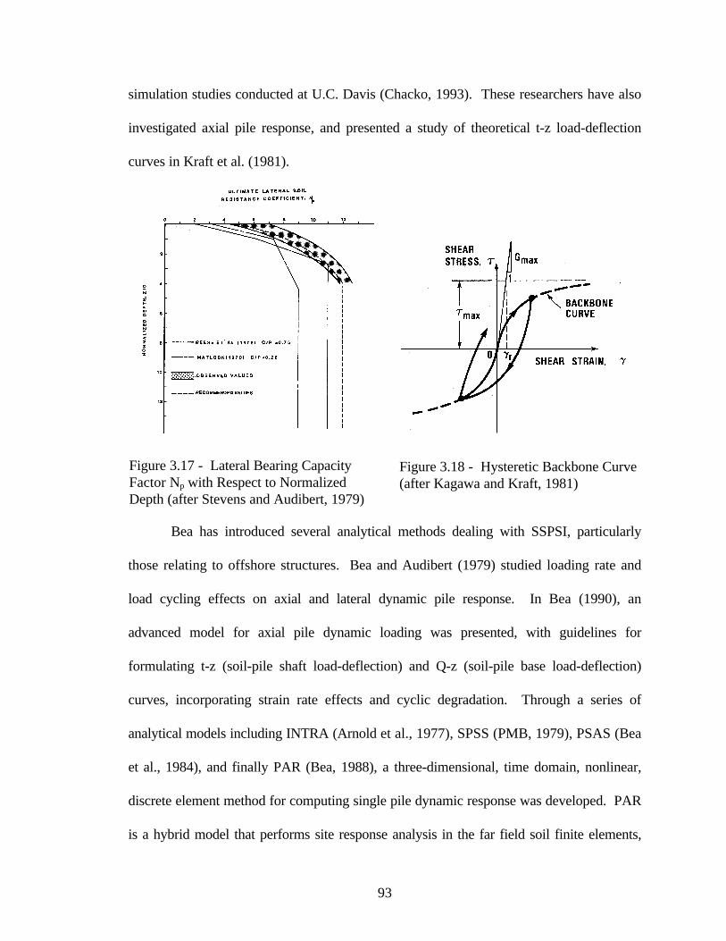
Stevens and Audibert (1979) recast existing p-y curve formulations with a
dependency on pile diameter. They noted that original p-y curve criteria were based on
field load tests of relatively small diameter piles, and by reviewing a broader database of
load test data they were able to derive an expression for pile deflection proportional to the
square root of pile diameter. In addition, they proposed a modified profile of lateral soil
resistance with an ultimate value of 11 SuB, as shown in Figure 3.17.
O’Neill and Murchison (1983) carried out a systematic evaluation of p-y
relationships in sands and compared the predictive accuracy of four methods against a set
of pile load test data. The methods tested included the segmented curve of Reese et al.
(1974), a modification suggested by Bogard and Matlock (1980), a bilinear representation
proposed by Scott (1979), and a continuous hyperbolic tangent curve described by Parker

92
and Reese (1970). The hyperbolic curve proved to be the most accurate for both static
and cyclic loading, and relatively easy to implement. The form of the p-y curve is given by
= ypA
kzpApu
u tanhη (3.3)
where η = 1 for circular, prismatic piles, A is a factor for static or cyclic loading, k is the
initial modulus of subgrade reaction, z is depth, and pu is determined from equations for
wedge type and deep flow failure mechanisms. Ironically, Bogard and Matlock’s (1980)
simplified method has found greater acceptance than this more accurate approach. In a
similar vein, O’Neill and Gazioglu (1984) investigated p-y relationships in cohesive soils,
and attempted to develop a unified method for both soft and stiff clay, but this method has
not been widely adopted.
Kagawa and Kraft (1980) developed a nonlinear dynamic Winkler model using the
equivalent linear method, with input excitation applied as lateral ground displacements at
the end of the near-field soil elements. The pile was modeled by a continuous beam with
near field soil elements comprised of parallel springs and dashpots, and with
superstructure elements that generated the inertial component of response. Soil spring
stiffness values were determined from the hysteretic backbone curve as shown in Figure
3.18, and the radiation damping dashpot coefficient was computed as
( )VVBc SPS += ρ2 (3.4)
In Kagawa and Kraft (1981), the nonlinear soil model was formulated as an effective
stress model, and cyclic degradation of soil resistance was governed by pore pressure
generation. This model has been incorporated in the computer code NONSPS
(McClelland Engineers, 1983) which has achieved only fair performance in recent model
93
simulation studies conducted at U.C. Davis (Chacko, 1993). These researchers have also
investigated axial pile response, and presented a study of theoretical t-z load-deflection
curves in Kraft et al. (1981).
Bea has introduced several analytical methods dealing with SSPSI, particularly
those relating to offshore structures. Bea and Audibert (1979) studied loading rate and
load cycling effects on axial and lateral dynamic pile response. In Bea (1990), an
advanced model for axial pile dynamic loading was presented, with guidelines for
formulating t-z (soil-pile shaft load-deflection) and Q-z (soil-pile base load-deflection)
curves, incorporating strain rate effects and cyclic degradation. Through a series of
analytical models including INTRA (Arnold et al., 1977), SPSS (PMB, 1979), PSAS (Bea
et al., 1984), and finally PAR (Bea, 1988), a three-dimensional, time domain, nonlinear,
discrete element method for computing single pile dynamic response was developed. PAR
is a hybrid model that performs site response analysis in the far field soil finite elements,
Figure 3.17 - Lateral Bearing CapacityFactor Np with Respect to NormalizedDepth (after Stevens and Audibert, 1979)
Figure 3.18 - Hysteretic Backbone Curve(after Kagawa and Kraft, 1981)

94
and models soil-pile interaction with near field springs and dashpots (see Figure 3.19).
Provisions for progressive gapping, cyclic degradation, and radiation damping are
included, but pile group effects must be accounted for externally.
Figure 3.19 - PAR Analytical Model (after Bea et al., 1984)
Nogami also developed hybrid near field/far field soil-pile interaction models for
dynamic loading, as shown schematically in Figure 3.20. He formulated solutions for
single pile and pile group axial and lateral response in both the time and frequency
domains, incorporating nonlinear soil-pile response, degradation, gapping, slip, radiation
damping, and loading rate effects (Nogami et al., 1991; Nogami et al., 1992). In Nogami
(1985) and Nogami and Konagi (1988), the transfer matrix approach was described that
was used to solve the equations of motion for a pile subject to soil-pile interaction forces,
functions of the near field and far field soil element properties. Nogami (1991) makes a
detailed comparison of the features and performance of Matlock’s, Novak’s, and
Nogami’s Winkler foundation models for lateral pile response. Nogami’s far field

95
(a)
(b)Figure 3.22 - Nogami’s Inner Field and Near Field Soil-Pile Models for: a) Vertical
Excitation; b) Horizontal Excitation (after Otani et al., 1991)
Figure 3.20 - Nogami’s Beam-on-Winkler Foundation Soil-PileInteraction Model(after Nogami et al., 1988)
Figure 3.21 - Nogami’s Far Field Soil-PileModels for: a) Vertical Excitation; b) HorizontalExcitation (after Nogami et al., 1988)

96
element consisted of three Kelvin-Voigt parallel spring-dashpot pairs designed to simulate
an infinite elastic plane strain medium, and a shear element in series to simulate interaction
of adjacent soil layers (Figure 3.21). The near field element was a nonlinear spring, with
mass to simulate near field inertial effects (Figure 3.22). Gapping was provided by an
elasto-plastic interface element. Nogami’s models can be used to compute pile head
impedance functions, or input excitations can be directly applied to the discrete end nodes
of the model. As will be described in section 3.3.9, WSDOT favorably evaluated a
Nogami soil-pile interaction model in a SSPSI study they conducted; this represents the
sole example in the literature of Nogami’s model being coded for computer applications.
Makris and Badoni (1995a) introduced a so-called macroscopic model based on
the Bouc-Wen model of visco-plasticity, which used distributed nonlinear springs to
approximate the soil-pile reaction. Limits of soil resistance were based on the work of
Broms (1964), Randolph and Houlsby (1984), and Matlock (1970). Radiation damping
was provided by a frequency dependent viscous dashpot that attenuated at large pile
deflections. The model accommodated pile head loading, and required that two
parameters be fit by experimental data. Validation against five case studies was provided.
Makris (1994) has also presented an analytical solution for pile kinematic response due to
the passage of Rayleigh waves, applicable to near field earthquake response.
Pender and Pranjoto (1996) updated a nonlinear soil-pile interaction model
originally proposed by Carter (1984) to include the effects of gapping. Compression-only
springs were attached to both sides of the pile, preloaded to reflect the effects of pile
installation, and provided with the ability to detach and form a gap when the spring force
reached zero. A hyperbolic form of the nonlinear spring stiffness was adopted, defined by

97
initial stiffness and ultimate resistance parameters. The model very well demonstrated
progressive gapping with depth and with the number of load cycles, and the consequent
reduction in pile head lateral stiffness. The authors acknowledged the need to extend the
model to dynamic loading.
3.1.3 Elastic Continuum
The elastic continuum analytical method is based on Mindlin’s (1936) closed form
solution for the application of point loads to a semi-infinite mass. The accuracy of these
solutions is directly related to the evaluation of the Young’s modulus and the other elastic
parameters of the soil. This approach is limited in the sense that nonlinear soil-pile
behavior is difficult to incorporate (the equivalent linear method is available), and it is
more appropriately applied for small strain, steady state vibration problems. In addition,
layered soil profiles cannot be accommodated, and only solutions for constant, linearly
increasing, and parabolically increasing soil modulus with depth have been derived. True
continuum models do have the advantage of intrinsically modeling the effects of radiation
damping, whereas discrete models must artificially simulate this energy dissipation mode.
Tajimi (1966) was the first to describe a dynamic soil-pile interaction solution
based on elastic continuum theory. He used a linear Kelvin-Voigt visco-elastic stratum to
model the soil and ignored the vertical components of response. His basic method has
been modified and extended by Tazoh et al. (1988) and other researchers to include
superstructure inertial effects.
Poulos has been a major progenitor of elastic solutions for soil and rock
mechanics, and has worked extensively on all aspects of pile foundation response to axial

98
and lateral loads. In Poulos (1971a, b) he first published elastic continuum solutions for
laterally loaded single piles and groups under static loading. Poulos and Davis (1980)
presented a comprehensive set of analysis and design methods for pile foundations based
on elastic continuum theory. Poulos (1982) described a procedure for degradation of soil-
pile resistance under cyclic lateral loading and compared it to several case studies. In a
different approach, Swane and Poulos (1984) proposed a subgrade reaction method that
provided for progressive soil-pile gapping with bilinear elasto-plastic springs and friction
slider blocks. In the 29th Rankine Lecture, Poulos (1989) presented a compendium of his
work on axial pile loading.
In 1974, Novak published the first of many papers dealing with pile dynamics,
where he adopted a plane strain, complex transmitting boundary adjacent to the pile for
solution of pile stiffness and damping coefficients. The plane strain condition is equivalent
to incorporating the Winkler assumption into the continuum model, and formed the basis
for his future work. Axial response of floating piles was considered in Novak (1977), and
the particular sensitivity of response to the pile tip condition, i.e. end-bearing or floating,
was noted. Novak and Aboul-Ella (1978) improved this model by considering layered soil
media, imperfect fixity of the pile tip, and material damping of the soil. Nogami and
Novak (1976) and Novak and Nogami (1977) formulated more rigorous solutions for
axial and lateral pile response, respectively, in a linear visco-elastic medium in a similar
fashion as Tajimi (1966). To account for the development of soil nonlinearity adjacent to
the pile, Novak and Sheta (1980) proposed a cylindrical boundary zone around the pile
that was characterized by decreased modulus and increased damping relative to the free-
field, and with no mass to prevent wave reflections from the fictitious interface between

99
the cylindrical zone and the outer region. Novak and his co-workers have issued the
computer code DYNA4 (Novak, et al. 1993), which implemented their studies of single
and pile group lateral and axial dynamic response.
Gazetas and Dobry (1984) derived a method for substructuring the SSPSI problem
into kinematic and inertial components from a parametric finite element study based on the
work of Blaney et al. (1976). For the inertial interaction component, they described the
pile head dynamic stiffness by a complex valued impedance function of the form
ypCiK do=+ ω (3.5)
where K is the soil-pile stiffness, ω is the excitation frequency, C is the coefficient of
equivalent viscous damping, po is the amplitude of the forcing function, and yd is the
complex amplitude of the horizontal motion. Constant, linearly varying, and parabolically
varying soil modulus with depth cases were studied for single piles subjected to vertically
propagating shear waves. Kinematic interaction factors were graphically presented as
functions of D, B, Ep, Es, ω and site frequency f; these curves are multiplied against free-
field response spectra to yield design pile head response spectra. The authors also
considered the problem of dynamic pile response in layered soil profiles and described a
method whereby a static pile head stiffness was “corrected” to account for profiling, and
the overall damping value was obtained from a weighted average of dashpot coefficients
developed along the length of the pile. They also included a discussion of radiation
damping models and proposed a simplified plane strain version as a function of B, ρs, Vs,
and ω (see Figure 3.23). This model for radiation damping emanating from a laterally
oscillating pile consisted of zones of waves traveling at the soil shear wave velocity Vs,
and at Lysmer’s analog velocity VLa, where

100
)1(4.3
νπ −= V
V S
La(3.6)
The authors made the important note that at frequencies less than the natural frequency of
the system, there is no radiation damping. Gazetas (1991) made a complete survey of
foundation vibration problems and included detailed design charts and equations for direct
computation of pile head lateral and axial stiffness and damping coefficients in the three
above mentioned soil profiles. These expressions were a function of D, B, ρp, Ep, ρs, Es,
Vs, ω and soil damping β.
Figure 3.23 - One- and Two-Dimensional Radiation Damping Models(after Gazetas and Dobry, 1984)
Davies and Budhu (1986) and Budhu and Davies (1987, 1988) used the boundary
element method to develop convenient design equations for the analysis of static laterally
loaded fixed and free headed piles. They utilized an elastic continuum model that
accounted for nonlinear soil response with yield influence factors in profiles of both
101
constant and linearly varying soil modulus with depth. Application of this method to
cyclic or dynamic loadings was not made by these authors.
3.1.4 Finite Element Methods
The finite element method potentially provides the most powerful means for
conducting SSPSI analyses, but is has not yet been fully realized as a practical tool. The
advantages of a finite element approach include the capability of performing the SSPSI
analysis of pile groups in a fully-coupled manner, without resorting to independent
calculations of site or superstructure response, or application of pile group interaction
factors. It is of course possible to model any arbitrary soil profile, and to study 3-D
effects. Challenges to successful implementation of this technique lie in providing
appropriate soil constitutive models that can model small to very large strain behavior, rate
dependency, degradation of resistance, and still prove practical for use. Special features
to account for pile installation effects and soil-pile gapping should also be implemented.
Yegian and Wright (1973) implemented a finite element analysis with a radial soil-
pile interface element that described the nonlinear lateral pile response of single piles and
pairs of piles to static loading. Based on work by Kausel et al. (1975), Blaney et al.
(1976) used a finite element formulation with a consistent boundary matrix to represent
the free-field, subjected to both pile head and seismic base excitations, and derived
dynamic pile stiffness coefficients as a function of dimensionless frequency. Desai and
Appel (1976) presented a three dimensional finite element solution with interface elements
for the laterally loaded pile problem. Emery and Nair (1977) studied an axisymmetric
finite element model that incorporated non-symmeteric free-field acceleration boundary

102
excitations from wave propagation analyses. Randolph and Wroth (1978) modeled the
linear elastic deformation of axially-loaded piles. Kuhlemeyer (1979a) offered efficient
static and dynamic solutions for lateral soil-pile elastic response; Kuhlemeyer (1979b) used
a finite element model of dynamic axially loaded piles to verify Novak’s (1977) solution
and a simplified method presented by the author. Angelides and Roesset (1981) extended
Blaney’s work with an equivalent linearization scheme to model nonlinear soil-pile
response. Force-deflection relations were developed and compared favorably with p-y
curves suggested by Stevens and Audibert (1979). Randolph (1981) derived simplified
expressions for the response of single piles and groups from a finite element parametric
study. Dobry et al. (1982) made a parametric study of the dynamic response of head
loaded single piles in uniform soil using Blaney’s method and proposed revised pile
stiffness and damping coefficients as a function of Es and Ep. Kay et al. (1983) promoted a
site-specific design methodology for laterally loaded piles consisting of pressuremeter test
data as input to an axisymmetric finite element program. Lewis and Gonzalez (1985)
compared field test results of drilled piers to a 3-D finite element study that included
nonlinear soil response and soil-pile gapping.
Trochianis et al. (1988) investigated nonlinear monotonic and cyclic soil-pile
response in both lateral and axial modes with a 3-D finite element model of single and
pairs of piles, incorporating slippage and gapping at the soil-pile interface. They deduced
a simplified model accommodating pile head loading only. Koojiman (1989) described a
quasi-3-D finite element model that substructured the soil-pile mesh into independent
layers with a Winkler type assumption. Brown et al. (1989) obtained p-y curves from 3-D
finite element simulations that showed only fair comparison to field observations. Wong

103
et al. (1989) modeled soil-drilled shaft interaction with a specially developed 3-D thin
layer interface element. Bhowmik and Long (1991) devised 2-D and 3-D finite element
models that used a bounding surface plasticity soil model and provided for soil-pile
gapping. Brown and Shie (1991) used a 3-D finite element model to study group effects
on modification of p-y curves. Urao et al. (1992) contrasted results from a dynamic 3-D
finite element analysis of a composite pile/ diaphragm wall foundation with an
axisymmetric model. Cai et al. (1995) analyzed a 3-D nonlinear finite element subsystem
model consisting of substructured solutions of the superstructure and soil-pile systems. In
companion papers, Wu and Finn (1997a, b) presented a quasi-3-D finite element
formulation with relaxed boundary conditions that permitted: a) dynamic nonlinear
analysis of pile groups in the time domain, and b) dynamic elastic analysis of pile groups in
the frequency domain. These methods showed good comparison to more rigorous
techniques, but at reduced computational cost. Fujii et al. (1998) compared the results of
a fully-coupled 2-D effective stress SSI model to measured performance of a pile-
supported structure in the Kobe earthquake.

104
3.1.5 Pile Group Effects
The results of single soil-pile interaction analyses must be extended to reflect the
group configurations piles are typically installed in for accomplishing full SSPSI analyses.
This is in contrast to substructuring or complete analysis methods which inherently
consider the entire group response. If piles are arrayed in groups with large pile-to-pile
spacings (greater than 6 - 8 pile diameters), pile group interaction effects are normally
ignored for static loading (see Figure 3.24). But this may be an inaccurate approach for
dynamically loaded piles, as much of the pile group interaction effects arise from wave
energy reflected between neighboring piles, which does not attenuate as rapidly as static
loading pile group interaction. Pile group dynamic response is also a function of load
level; many of the group analysis methods that will be described address small strain elastic
response, and few researchers have investigated nonlinear pile group interaction. There is
evidence however to suggest that pile group effects lessen with increasing soil-pile
nonlinearity, which inhibits wave energy transmission between piles.
Figure 3.24 - Pile Group Interaction as Function of Pile Spacing(after Bogard and Matlock, 1983)

105
The behavior of a pile group subjected to lateral loading and overturning moment is
shown in Figure 3.25, which illustrates the components of pile group response. These
components include:
• group rotation, inducing axial tensile/compressive forces, most severe at end piles,
• group translation and relative pile translations,
• individual pile head rotations at pile to cap connections, and
• individual pile deflections and consequent bending moments.
The factors that influence the group response consist of:
• individual pile response: small strain elastic or nonlinear behavior,
• loading: static, cyclic, or dynamic; transient or steady state,
• soil properties, particularly as modified by pile group installation,
• relative soil-pile stiffness; more flexible piles experiencing greater interaction,
• group geometry, including individual pile cross sections and group spacing,
• head fixity, idealized as free head or fixed head, but in actuality an intermediate case,
• tip condition, either floating or end-bearing,
• superstructure mass and flexibility, which impart inertial loads to the pile group, and
• pile cap embedment depth, stiffness and damping characteristics.
The objectives of conducting a pile group analysis are to determine the following:
• pile group and individual pile deflections,
• individual pile head shear forces and moment distributions, and
• modifications to the input ground motion for superstructure analysis.
The manner in which this is accomplished relates to the level of single pile analysis.
Single pile kinematic response analyses can be modified to approximate group effects and
superstructure influence. Single pile impedance functions can be assembled into group
impedance functions with a group interaction theory. The group impedance function is
then used in a global structural analysis, which produces forces and deflections on the pile

106
group. These forces and deflections can then be distributed to the individual piles with
group interaction theory, and individual pile head forces can be checked not to exceed the
pile to cap connection capacity. Then the most critically loaded pile(s) in the group can be
assessed in a single pile integrity analysis mode to determine whether pile moment
distributions exceed capacity. To determine the effect of the pile group on modifying
ground motions input to the superstructure, the analysis must be either conducted in a true
substructuring fashion; or alternatively, this effect can be captured in a complete SSPSI
analysis.
Figure 3.25 - Components of Pile Group Response Under Lateral Loading(after O’Neill and Dunnavant, 1985)
In the following sections, static and dynamic pile group response theories will be
presented, defined as one of two categories: 1) pile group interaction methods, used in
relating single pile analysis results to group behavior; 2) pile group complete dynamic
analyses, where the entire group response is analyzed in one step. Reviews of pile group
dynamic response are provided by Roesset (1984) and Novak (1991).

107
3.1.5(a) Pile Group Interaction Methods
Poulos (1971) introduced the concept of pile group interaction factors. He used
Mindlin’s elasticity equations to solve for stresses and displacements between pairs of piles
due to horizontal point loads applied in an elastic half space. Poulos described interaction
factors as:
loading own its todue pile of (rotation)nt displaceme
pileadjacent todue (rotation)nt displaceme additional=α (3.7)
He presented charts of α factors for both fixed and free head piles subject to lateral and
moment loadings as functions of pile flexibility Kr (see Table 3-1), pile spacing, pile
diameter, pile length, and departure angle (angle between piles and direction of loading).
Analysis of groups was accomplished by superposition, calculating each pile’s interaction
with all other piles in the group, and ignoring the presence of intervening piles.
Subsequently, his method has proved to underestimate pile group interaction at small pile
spacings and overestimate interaction at large spacings. Poulos elaborated this method to
include soil limit pressures, soil-pile axial slip, variation of soil modulus with depth, and
batter piles in the computer code DEFPIG (Poulos, 1980). Randolph and Poulos (1982)
presented a simplified flexibility matrix method for pile group response based on Poulos’
axial interaction factors and Randolph’s (1981) lateral interaction factors. In Poulos and
Randolph (1983), these two methods are compared. Randolph (1986) also issued the pile
group analysis program PIGLET, based on parametric finite element analyses.
Focht and Koch (1973) combined Poulos’ elastic interaction factors with nonlinear
p-y analysis in a hybrid model to predict group deflections and shear load distributions.
They conceived of pile group interaction to consist of two components, nonlinear soil
108
response close to the piles, and an elastic component at intermediate ranges between piles.
The analysis procedure consisted of first computing a single pile mudline deflection from
conventional p-y analysis, then computing a Poulos interaction factor-derived deflection at
the mudline, the latter based on a low stress level in the soil. Individual pile deflections
and shear forces were then estimated from integrating the plastic and elastic deformations,
and the total group response was solved for. The variations of deflection and moment
with depth on individual piles was then constructed from conventional p-y data modified
by “Y” factors, accounting for the elastic components of interaction. The authors
recognized the uncertainty in selecting values of soil modulus for elastic interaction, but it
has proven to be a viable tool for pile group analysis under static and cyclic loading.
Reese et al. (1984) suggested modifications to the relative stiffness factor R in this
procedure.
Bogard and Matlock (1983) introduced the modified unit transfer load method,
which developed p-y curves for group piles by considering an imaginary pile with a
diameter equal to the pile group diameter. As shown in Figure 3.26, the group pile p-y
curve is constructed by summing the single pile deflection with the pile group soil mass
deflection at a given soil pressure. This method was developed for static and cyclic
loadings of a circular pile group in soft clay, and its extension to other group geometries
and conditions is unproven.
O’Neill and Dunnavant (1985) surveyed static laterally loaded pile group
interaction analyses, and compared the hindcast performance of four methods against a
database of 16 pile group load tests. The methods evaluated included the Focht-Koch
hybrid analysis, the Bogard-Matlock modified unit load transfer method, a plane strain

109
interaction procedure (Hariharan and Kumarasamy, 1982), and the PILGP2R hybrid
method, proposed by the authors. The plane strain interaction procedure consisted of
analyzing stresses and displacements in an elastic layer produced by the displacement of a
rigid embedded disk. The PILGP2R hybrid model overcame a limitation of the Focht-
Koch model, providing for a variation in Y-multipliers over the pile depth, rather than a
single value applied to the entire pile. Overall, the study showed the PILGP2R model to
provide the best estimates of average behavior of group piles, of initial group lateral
stiffness, and load distribution, but it was found to underpredict deflections and moments
at high load levels.
Figure 3.26 - Pile Group Unit Load Transfer Method (after Bogard and Matlock, 1983)
Brown et al. (1987) performed cyclic lateral load tests on 3x3 pile groups in stiff
clay and sand (see Chapter 4), and proposed the concept of p-multipliers to account for
group effects. The p-multipliers are reduction factors applied to the p-y relationship
computed for an individual pile of the group. These reduction factors are a function of
pile spacing and orientation to loading, and are implemented in the pile group analysis
program GROUP (Reese et al., 1994).

110
Ooi and Duncan (1994) presented the group amplification procedure for laterally
loaded pile groups, which was derived from single pile analyses by the characteristic load
method (Duncan et al., 1994) and group interaction using the Focht and Koch (1973)
procedure. Their parametric studies yielded a deflection amplification factor
( ) ( )( )PCPDSBNAC
N
piley
s++= 5.0 (3.8)
where A, B, and C are factors for clay and sand soils, Npile is the number of piles, S is the
average pile spacing, D is the single pile diameter, PS is the total lateral load on the pile
group, and PN = SUD2 for clay and KPγD3 for sand. A simplified procedure was also
presented for estimating the maximum bending moment in the most critically loaded pile in
the group. The method applied to statically loaded, vertical, uniformly spaced, fixed head,
flexible piles embedded in a homogeneous soil. Validation against several case histories
was provided, with reasonable accuracy attained.
Kaynia and Kausel (1982) derived dynamic interaction factors for floating pile
group interaction analysis by combining a numerical integration for the evaluation of the
influence coefficients with an analytical solution for the pile stiffness and flexibility
matrices. This boundary element formulation computed Green’s functions from imposed
barrel and disk loads in a homogeneous soil medium, and used a consistent stiffness matrix
to account for the far field. Their interaction factors were presented as complex-valued
frequency dependent ratios of the dynamic displacement of pile i to the static displacement
of pile j, due to a unit harmonic load on pile j. Vertical and horizontal interaction factors
are shown in Figure 3.27, demonstrating positive and negative group efficiencies.
Normalized dynamic stiffness and damping of a 4x4 pile group for different spacings is

111
shown in Figure 3.28, indicating the strong frequency dependence of dynamic group
response. They also derived expressions for the distribution of forces over the pile group
(see Figure 3.29), which was shown to vary from static loading force distributions. Other
important conclusions from this study were that the superposition technique is valid for
dynamic pile group solutions (in homogeneous soil), pile groups are less influenced by
near-surface ground conditions than isolated piles, group interaction effects are stronger
for softer soil, and radiation damping increases with foundation size.
Figure 3.27 - Vertical and Horizontal Dynamic Pile Interaction Factors(after Kaynia and Kausel, 1982)

112
Figure 3.28 - Normalized Horizontal and Vertical Dynamic Stiffness and Damping of 3x3Pile Group in Soft Soil (after Kaynia and Kausel, 1982)
Figure 3.29 - Distribution of Horizontal and Vertical Forces in 4x4 Pile Group inSoft Soil Medium (after Kaynia and Kausel, 1982)

113
In companion reports, Sanchez-Salinero (1982, 1983) investigated single pile and
pile group dynamic response. Using static and dynamic axial and lateral single pile head
stiffness coefficients as indices, he compared the values computed by the methods of
Poulos (1971), Penzien (1964), Kuhlemeyer (1979), Novak (1974), Blaney et al. (1976),
and Novak and Nogami (1977). For static lateral loads, Poulos’ method was found to
give lower stiffnesses and Kuhlemeyer’s approach was found to give higher stiffnesses,
with the other methods yielding similar intermediate values. For dynamic loads, Novak’s
Winkler assumption produced results comparable to Blaney’s more sophisticated
formulation. Sanchez-Salinero therefore extended the Winkler concept to an
elastodynamic boundary element formulation for developing pile group interaction factors.
He contrasted point and disk pile approximations, and verified the validity of the
superposition technique. The strong frequency dependence of pile group stiffness
coefficients was noted, with the author concluding that the effects of soil nonlinearity on
pile group response may significantly affect the results.
Dobry and Gazetas (1988) presented a simplified method for calculating dynamic
pile interaction factors in homogeneous soil by assuming that cylindrical wave propagation
governs vibration of source piles and displacement of neighboring piles. Fan and Gazetas
(1991) studied pile group kinematic interaction effects, and as shown in Figure 3.30, the
generalized pile head to free-field transfer function illustrates the pile group effect in
filtering out high frequency components of motion. They found that pile group
configuration and spacing have little influence on kinematic response, as pile head fixity
and relative soil-pile stiffness play a stronger role. Gazetas and Makris (1991) and Makris
and Gazetas (1992) developed simplified methods of analysis for pile group axial and

114
lateral dynamic response, respectively (see Figure 3.31). Using a dynamic Winkler model,
they found pile group effects to be more pronounced for inertial than kinematic loading.
The substructuring approach unifying the kinematic and inertial analyses is described in
Gazetas et al. (1992), and is shown schematically in Figure 3.32. Mylonakis et al. (1997)
applied this substructuring approach in an equivalent linear method to analyze pile-
supported bridge piers.
Figure 3.30 - Generalized Pile Head/Free Field Transfer Function for KinematicInteraction (after Fan and Gazetas, 1991)
Figure 3.31 - Schematic of Three-Step Procedure for Computing Pile-Soil-PileInteraction (after Makris and Gazetas, 1992)

115
Figure 3.32 - Substructuring Method for Seismic Soil Pile Superstructure InteractionAnalysis (after Gazetas et al., 1993)

116
3.1.5(b) Pile Group Complete Dynamic Analyses
Wolf and von Arx (1978) generalized the solution of Blaney et al. (1976) to
publish the first pile group complete dynamic response analysis method. They considered
a horizontally layered visco-elastic soil deposit with piles of equal diameter and length,
either floating or endbearing, in any group configuration. They used an axisymmetric
finite element model to calculate the Green’s functions producing the displacements at any
point in the soil mass given a ring load applied at a discrete layer. The Green’s functions
were then used to compute the flexibility matrix of the soil at each frequency, and the
dynamic stiffness matrix of the complete system was then assembled. The results
displayed strong dependence on frequency, number of piles, and pile spacing. Wolf
(1980) detailed procedures for calculating the dynamic stiffnesses of groups of battered
piles. Most recently, Wolf et al. (1992) described simplified but reasonably accurate cone
models for single pile and pile group dynamic response.
Waas and Hartmann (1981) analyzed pile groups arrayed in concentric rings, and
assumed that the radial, vertical, and tangential components of displacement were
proportional to the direction of applied loading. They substructured the problem (see
Figure 3.33) and determined the flexibility matrix of the visco-elastic soil deposit with
applied point and ring loads, for coupling to the structure/pile stiffness matrix. They
suggested that nonlinear soil behavior could be modeled by an equivalent linear analysis,
and that rectangular pile groups could be transformed into equivalent circular groups
amenable to their analysis technique. Their analysis clearly demonstrated the effects of
kinematic and inertial interaction as shown in Figures 3.34a - d.

117
Figure 3.33 - Separation of SSPSI Analysis into Kinematic and Inertial InteractionComponents (after Waas and Hartmann, 1981)
(a) (b)
(c) (d)
Figure 3.34 - a) Definition of Transfer Function; b) Transfer Function without BuildingMass for Soft Soil; c) Transfer Function without Building Mass for Stiff Soil; d) Transfer
Function for Different Building Masses in Stiff Soil (after Waas and Hartmann, 1981)

118
Kagawa (1983) used elastic wave propagation to compute soil displacements and
reactions between pairs of piles for the derivation of pile group stiffness and damping
coefficients. Both vertical and lateral interaction were considered, as well as pile head
fixity condition. These values were found to be dependent on pile spacing, departure
angle, and frequency. Dynamic pile group impedance efficiencies both in excess of and
less than one were calculated. Kagawa (1991) adopted a substructuring approach to the
pile group dynamic response problem, as shown in Figure 3.35. In this method, the
stiffness of the superstructure with piles was calculated by conventional means, and the
load displacement relations for the cylindrical cavities obtained from a flexibility analysis.
The flexibility analysis consisted of applying ring loads to one cavity, and computing
displacements in the neighboring cavity (Figure 3.36); Kagawa noted that compatibility
conditions are often relaxed in this type of analysis for computational efficiency. By
formulating a more rigorous method, Kagawa was able to demonstrate a moderate loss in
analytical accuracy when using relaxed compatibility conditions.
Sheta and Novak (1982) investigated the effects of soil nonlinearity on pile group
axial dynamic response by means of including a cylindrical weak zone surrounding floating
or endbearing individual piles. Figure 3.37 demonstrates that group interaction effects
elevate the response peaks, while the inclusion of a weak boundary zone serves to dull the
peaks, but not eliminate them. El Sharnouby and Novak (1984) described a method of
analysis of pile group interaction under static axial and lateral loading that yielded
interaction factors, and was found to compare reasonably well with other accepted
analyses (This method was updated by the authors in 1990).

119
Mitwally and Novak (1987) presented complex, frequency dependent interaction
factors for dynamic pile group response of offshore structures, with the recommendation
that the equivalent linear method be employed to simulate nonlinear soil-pile response.
The authors evaluated the effects of including pile group interaction effects on the
response of a pile-supported platform subjected to wave loading; the results shown in
Figure 3.38 illustrate the frequency dependence of group interaction. El-Marsafawi et al.
(1992) derived pile group dynamic interaction factors from a boundary integral
formulation for floating and end-bearing piles in homogeneous or non-homogeneous soil
deposits. They also verified the applicability of the superposition approach for the
conditions studied, with some limitations. A set of translation, rotation, translation-
rotation coupling, fixed head, and vertical interaction factors were described in terms of
Figure 3.35 - Example of SubstructuringApproach (after Kagawa, 1991)
Figure 3.36 - Soil Displacements dueto Ring Loading (after Kagawa, 1991)

120
amplitude and phase angle, a more convenient form for interpolation than real and
imaginary stiffness terms. The authors concluded that the superposition method worked
well except for cases of vertical response of stiff end-bearing piles, and the high frequency
range for nonhomogeneous soils.
Figure 3.37 - Dynamic Response of Pile Supported Foundation Indicating Influence ofGroup Effects and Weak Zone (after Sheta and Novak, 1982)
El Naggar and Novak (1994a) described a nonlinear model for dynamic axial pile
response that consisted of a slip zone, inner field, and outer field (see Figure 3.39) that
simulated a variety of field test results with great success. El Naggar and Novak (1994b)
presented chart solutions for pile group interaction factors derived from this model. Most
recently, El Naggar and Novak (1995) described a dynamic nonlinear time-domain
Winkler soil-pile interaction model that allowed for both axial and lateral pile group
response. The axial model consisted of a linear outer region and a nonlinear inner field
connected to the pile by a plastic slider allowing for soil-pile slip. The lateral response
mode also consisted of inner and outer fields with formulations by Novak and Aboul-Ella

121
Figure 3.38 - Platform Response to Wave Loading with Pile Group Interaction bothConsidered and Neglected (after Mitwally and Novak, 1987)

122
Figure 3.39 - Nonlinear Model for Dynamic Axial Response of Single Pile(after El Naggar and Novak, 1994b)
Figure 3.40 - Nonlinear Model For Dynamic Lateral Response of Pile Groups(after El Naggar and Novak, 1995)

123
(1978) and Novak and Sheta (1980) but with the addition of a directional gapping model.
Interpile springs were used to model lateral and axial pile group effects (see Figure 3.40).
They found that nonlinear foundation response is more pronounced for nonhomogeneous
soil profiles than homogeneous ones, and that the nonlinear foundation behavior decreases
the structural damping ratio, but this is more than offset by the increase in foundation
damping. They also concluded that dynamic pile group effects increase foundation
damping, significantly for linear conditions, but to a lesser extent for nonlinear conditions.
Nogami (1979) presented solutions for the dynamic axial response of pile groups
in homogeneous soil profiles. Nogami and Konagi (1987) studied nonlinear pile group
axial response by incorporating slip at the soil-pile interface in a dynamic Winkler model.
They found this nonlinearity to reduce wave interference effects and suppress the
frequency dependence of dynamic group response. Nogami et al. (1988) and Otani et al.
(1991) extended the dynamic Winkler pile group model to lateral loading, and included
slip, gapping and inelastic soil behavior. Their nonlinear near field model was found to
dull the peaks of computed pile head impedance functions. Unfortunately, Nogami has
not presented his work in a form convenient for use by the profession, and it remains
underutilized and not well validated.
In addition to studying pile group interaction under static loading, Banerjee has
also researched pile group dynamic interaction effects. Banerjee and Davies (1980)
compared the results of a boundary element formulation pile group analysis method with
static loading field case histories. Banerjee and Sen (1987) reported on boundary element
formulations for pile group dynamic response. They also investigated the effects of a
ground contacting massless pile cap, and found a marginal increase in pile head impedance
124
of small floating pile groups, most pronounced for the damping component. Mamoon
(1990) conducted an extensive study of cap effects on dynamic group response. He
accounted for pile cap inertia, but ignored the shear stress in the mat base. An important
conclusion from this study was that pile cap inertia can reduce the sharp peaks in the
dynamic response.
Makris and Badoni (1995b) followed their earlier work with a simplified method
for analysis for pile groups subject to obliquely incident shear and Rayleigh waves, with
spring and dashpot coefficients evaluated from the techniques described in Makris and
Gazetas (1992). The method consisted of computing the difference between single
“source” piles and free-field response, and propagating it to neighboring “receiver” piles.
By superposition, the pile group displacement, rotation, and individual pile head forces
were obtained, incorporating both kinematic and inertial sources of loading. The results
from this approximate method were found to compare very favorably to methods by
Mamoon and Banerjee (1990), and Kaynia and Novak (1992). In a comprehensive report
encapsulating Badoni’s Ph.D. dissertation work, Badoni and Makris (1997) summarize
numerical analysis methods for structures incorporating nonlinear axial and lateral soil-pile
group interaction, as well as structural nonlinearity and pile yielding.
The complex response method finite element computer programs FLUSH (Lysmer
et al., 1975) and SASSI (Bechtel, 1991), through principally designed for soil-structure
interaction analyses, do have the capability of modeling SSPSI as a complete analysis, but
are not well equipped to deal with strong soil-pile nonlinearity, gapping, etc. The
generalized finite element code DRAIN2D-X (Prakash et al., 1993) has also been used by
a number of researchers as a platform for SSPSI analyses.

125
3.2 Building Code Provisions
This section will examine the myriad of building code recommendations for
conducting soil-structure interaction design and analyses, and provisions for dealing with
the seismic performance of pile foundations. Although many of these codes incorporate
simplified soil-structure interaction analysis methods, they acknowledge the need for site-
specific studies for structures on soft soils subject to strong levels of shaking. First, codes
dealing with building structures will be reviewed, followed by those pertaining to bridges.
3.2.1 Uniform Building Code / SEAOC Recommendations
The 1997 Uniform Building Code (ICBO, 1997) and the companion Blue Book
Recommended Lateral Force Requirements and Commentary (SEAOC, 1996) do not
provide any overt requirements for consideration of soil-structure interaction. Chapter 18
of the UBC, “Foundations and Retaining Walls”, provides minimal design guidance for
foundation construction in seismic zones 3 and 4, but emphasizes consideration of the
potential for soil liquefaction or strength loss. Specific requirements for steel pile width to
thickness ratios and concrete pile transverse reinforcement are given. An emphasis is also
placed on the capacity of the foundation to sustain the base shear and overturning forces
transmitted from the superstructure and for the adequacy of superstructure to foundation
connections. The SEAOC recommendations call general attention to cyclic degradation,
pile group effects, pile cap resistance, pile flexure and ductility, and kinematic loadings,
but offer no specific requirements for design. Chapter 16 of the UBC, “Structural Design
Requirements”, provides for both response spectrum and time history analyses for

126
earthquake design; however there are no provisions to account for soil-structure
interaction in either method. In essence, the UBC partially addresses pile integrity under
kinematic and inertial loading, but does not explicitly account for the influence of the pile
foundation on the ground motions imparted to the superstructure.
3.2.2 National Earthquake Hazard Reductions Program
The 1997 NEHRP Recommended Provisions for Seismic Regulations for New
Buildings and Other Structures (BSSC, 1997) includes detailed procedures for
incorporating the effects of soil-structure interaction in the determination of design
earthquake forces in the structure. Incorporating these effects has the direct result of
reducing the base shear applied to the structure, and consequently the lateral forces and
overturning moments, but may increase lateral displacements (due to rocking). The
maximum permissible base shear reduction factor is 30 %, and it is computed as a function
of flexible base period and damping factors. The flexible base period is a composite of
fixed base, flexible rocking, and flexible translational periods, the latter two computed
from foundation stiffnesses.
The accompanying Commentary presents a procedure for deriving the foundation
stiffness factors from a simple model of a rigid mat bonded to an elastic halfspace. The
model can take into account foundation shape, embedment, and soft soil over stiff layer,
but the Commentary acknowledges that its application to pile foundations is more
tenuous. This is the type of model that Stewart investigated (see chapter 2), and his
findings echoed this conclusion. The Commentary states that individual pile stiffness
factors may be determined from field tests or beam-on-elastic-subgrade analyses, but

127
provides scant details. Perhaps unconservatively, the Commentary recommends summing
individual pile stiffness factors to compute pile group stiffness, without reduction factors.
The 1997 NEHRP Guidelines for the Seismic Rehabilitation of Buildings (BSSC, 1997)
provides simplified expressions for pile axial and rocking stiffness and the influence of pile
caps on pile group seismic response. For cases where the piles may significantly
contribute to lateral stiffness (i.e., soft soils, battered piles), the Provisions recommend
that a beam-column analysis be performed. In promoting an elastic model of soil-structure
interaction, the NEHRP Provisions do not directly incorporate nonlinear effects, but
attempt to overcome this limitation by recommending that foundation stiffness factors be
selected based on anticipated strain levels in the soil response.
The NEHRP foundation design requirements primarily focus on assuring adequate
pile cap connections, transverse reinforcement, and the ability to withstand maximum
imposed curvatures resulting from seismic loading. These curvatures are observed to
potentially arise from: 1) soil settlement beneath the pile cap, leaving an unsupported pile
length in the zone of maximum inertial forces; 2) large deformations and/or reduction in
soil strength as a result of liquefaction; and 3) large deformations in soft soils, particularly
at soft/stiff soil interfaces.

128
3.2.3 Mexico City Building Code
The 1987 Mexico City Building Code carries with it lessons from the 1985 Mexico
City Earthquake (see Chapter 2). The Complementary Technical Norms (Gomez and
Garcia-Ranz, 1988) includes a simplified method for considering the effects of soil-
structure interaction. The objective of the procedure is to obtain a flexible-base period of
the structure for use with the response spectrum method, which is a weighted function of
the rigid base, flexible rocking, and flexible translational periods of the structure. Methods
for computing the rocking and translational stiffnesses of slabs, footings, friction, and end
bearing piles is included. Minimum spacing between structures is recommended as large
rocking displacements are possible. Foundation elements are to be designed “taking into
account a horizontal inertia force, acting on that volume of soil beneath them that
potentially would move during a shear soil failure... subject to a horizontal acceleration of
(0.04 - 0.15) g.” In summary, the Mexico City building code contains the basic elements
of the NEHRP provisions, specifically tailored for the longer period deep clay sites under
its jurisdiction, and is unique in that it attempts to differentiate the particular response of
pile foundations.
3.2.4 People’s Republic of China Aseismic Building Design Code
The 1989 People’s Republic of China Aseismic Building Design Code (PRC,
1989) states that “influences of soil-structure interaction may be disregarded in aseismic
structural analyses. When the soil-structure interaction is taken into account for highrise
reinforced concrete buildings with box-shaped or stiff raft foundations and constructed on
the Type III or IV site (softer soils), the seismic loads evaluated on the basis of the rigid-

129
foundation assumption may be diminished by 10 to 20 percent, their interstory drifts being
determined under the resulting reduction of story shear forces.” What this means is that
the code recognizes the beneficial effects of soil-structure interaction in period lengthening
and increased damping for longer period structures, thereby decreasing design forces, but
does not consider the potentially unconservative force increase for very short period
structures whose period lengthens on the ascending part of the response spectrum; nor
does it recognize potentially greater displacements due to rocking. With respect to piles,
the code requires piles in liquefiable layers to have minimum embedment in more stable
layers, but this requirement ignores the damage potential arising at zones of soil stiffness
contrast.
3.2.5 American Petroleum Institute Recommended Practice
The offshore oil industry has been a driving force behind the development of
analysis methods for the response of pile foundations under lateral cyclic loading, primarily
due to wave loading of pile-supported offshore drilling platforms. The API
Recommended Practice 2A-WSD (API, 1993) codifies the p-y type analysis method,
which is directly based on field tests conducted by Reese and Matlock in sands and clays.
Reduction factors for cyclic loading cases are given for both sands and clays, and the
sensitivity of axial capacity to cyclic lateral loading is also noted. With the enormous
investments and lack of redundancy in offshore drilling platforms, it is universal practice to
perform site-specific analyses, and not rely on published codes. A type of analysis known
as a “static push-over analysis” is commonly performed, which consists of building a finite
element model of the entire structure including the foundation piles and soil, and laterally

130
displacing the platform until yielding occurs in a component of the system; in this manner,
the designer can direct the system response. This formulation is convenient for offshore
platforms, which have a limited number of piles and structural elements, and the soil-pile
interaction is commonly modeled by p-y curves or a finite element mesh. Such a method
does not however capture the dynamic features of SSPSI, but it does succeed in coupling
the substructure and superstructure components of the system.
3.2.6 Improved Seismic Design Criteria for California Bridges
The 1996 ATC-32 Improved Seismic Design Criteria for California Bridges:
Provisional Recommendations (ATC, 1996) is a companion document to the current
Caltrans Bridge Design Specifications (BDS), and includes specific recommendations for
the seismic design of pile foundations. These recommendations are refinements of the
BDS, and take the form of presumptive values and simplified charts.
ATC-32 defines four types of bridges, two categories of seismic evaluation, and
four levels of analysis to be applied. Equivalent static analysis, conducted only for small
ordinary bridges, does not account for SSPSI. Elastic dynamic analysis, for which the
seismic design of most bridges is carried out, consists of a modal spectral analysis of a
finite element “stick model” of the bridge. The soil-pile rotational and translational
flexibilities are represented by linear elastic springs with secant stiffnesses based on
maximum load levels anticipated. The commentary cautions that development of
nonlinearity in the soil and other components of the structure are possible, but that the
elastic model can give good insights into system response. Inelastic static analysis is a
higher level evaluation required for important bridges and is used to examine inelastic

131
response of the bridge when subject to lateral displacements generated during the design
earthquake. This type of analysis, also known as a static push-over analysis, is intended to
capture the nonlinear response of the entire system, including nonlinear soil-foundation
interaction. Inelastic dynamic analysis may be performed in place of inelastic static
analysis; the type of soil-pile model for these inelastic analyses is not specified by ATC-32.
The commentary does make the interesting point that the seismic demand on the
foundation is an artifact of the analysis method; it also acknowledges that the methods
recommended only account for inertial loading from the superstructure into the piles, and
does not consider the effects of kinematic loading on the overall response of the structure.
The specifications require that pile foundations have sufficient capacity to resist
loads transmitted from the superstructure, while accounting for ductility developed in the
structure in the computation of these loads; adequacy of structural and connection details
is emphasized. Loads generated by ground movements and settlement should be
accounted for. The desired structural action is such that plastic hinges develop in elements
above the ground surface for inspection and repair accessibility, or that a sufficient load
path exists that directs failure into the soil, rather than the pile.
ATC-32 provides information on assigning foundation stiffness values based on
linear elastic response. It is important to emphasize that these stiffness values are
developed from static (or at best, cyclic) loading patterns, and are not true dynamic
stiffnesses. Lateral resistance is provided by piles and in some cases by passive pressure
on the sides of embedded pile caps, while bending stiffness is attributed only to the piles.
At stable soil sites, the resistance of the pile cap can contribute a significant lateral
stiffness to the pile footing, but at poor soil sites (liquefiable sands and soft clays), such

132
resistance is to be ignored. As axial capacity is provided by soil resistance at depth and
lateral capacity by shallow soil resistance, there is very little cross coupling between the
resistances and soil-pile interaction can be evaluated independently for the two modes of
loading. A table of presumptive lateral pile stiffness values is given, and is supplemented
by a series of simplified pile head stiffness charts based on a beam-on-elastic subgrade
reaction model; these charts provide stiffness values for a variety of pile head embedment
and boundary conditions. The specifications also define presumptive values for standard
Caltrans pile types for lateral capacity, tolerable foundation displacements up to 3.0 in, and
angular distortion up to 0.008 radians. With respect to nonlinear soil-pile interaction, the
capacity of piles to resist both axial compressive and tensile loads while accounting for the
effects of cyclic degradation of bearing capacity is addressed, particularly for friction piles,
piles at soft soil sites, and piles subject to skin friction shear stress reversal induced by
superstructure rocking. The commentary recommends that a site-specific analysis be
undertaken to determine pile stiffness and shear capacity at poor soil sites (liquefiable
sands and soft clays), cautioning that fully liquefied sands have a residual strength of only
about 10 % of the initial p-y curve resistance. At such sites, a number of design strategies
to resist the shear load are given, including the use of stronger connection details and
more ductile pile types.
In general, the seismic response of bridge structures is most sensitive to the
rotational component of stiffness of pile groups. According to the Commentary, pile
group effects for rotational response can be ignored for groups consisting of less than 20
piles at standard spacing, as their response is not in phase; relatively small group effects
are noted for translational response. Group effects are mitigated under cyclic loading at

133
soft soil sites, as the remolded soil is less effective in transferring stresses to neighboring
piles. However, group effects can become very important for large pile groups, and
special analyses are warranted in these cases. The effects of radiation damping dissipating
energy in the system are not accounted for.
The use of batter piles must be accompanied by proper understanding of their
performance and adequate detailing of connections and transverse reinforcement. At poor
soil sites subject to lateral ground movements, stiff batter piles tend to attract very large
forces compared to more compliant vertical piles, and their use is to be avoided. The pile
shaft, a continuous extension of the column into a foundation element, also has special
design guidelines, including a recommendation to increase the value of the modulus of
subgrade reaction used in computing p-y curves for shafts of diameter greater than 2 feet.
In summary, the ATC-32 guidelines provide a comprehensive and efficient method
for evaluating seismic response of bridge structures. They do not represent the state-of-
the-art for SSPSI, as a detailed nonlinear foundation model can be uneconomical for
complex bridge structures; but they do consider in a simplified fashion the principal modes
of SSPSI, and provide a very practical approach for bridge designers.
3.2.7 FHWA Seismic Design of Highway Bridge Foundations
The Federal Highway Administration has published a series of design manuals
addressing SSPSI for bridge structures, including Seismic Design of Highway Bridge
Foundations (1986). The lead authors of this manual, Lam and Martin, also participated
in the ATC-32 document, and the content is quite similar. Again, a simplified approach is
taken, which includes the use of equivalent linear frequency independent static pile head

134
stiffness terms, while ignoring radiation damping, pile group effects, and kinematic
loading. Nonetheless, due attention is given to nonlinear soil-pile interaction (p-y curve
method), liquefaction hazard, influence of rotational stiffness, load transfer, batter piles,
head fixity, pile cap stiffness, and special design procedures for drilled shafts.
3.2.8 Japanese Seismic Design Specifications for Highway Bridges
Kawashima and Hasegawa (1994) trace the history of seismic damage to highway
bridges in Japan and the consequent evolution of Japanese building codes. According to
the authors, the 1971 and 1980 specifications provided countermeasures against damage
of substructures caused by liquefaction and lateral spreading, and subsequent earthquakes
did not manifest damage in structures built to these standards. The 1990 specifications
included revisions that addressed the classification of ground conditions, the inertia force
applied to substructures, providing ductility in columns, and improvements in evaluating
the resistance of sandy soils to liquefaction (which has historically been the major pile
seismic hazard in Japan - see Chapter 2).
Unjoh and Terayama (1998) published a translation of the complete Seismic
Design Specifications of Highway Bridges, issued by the Japanese Public Works Research
Institute in 1996 to reflect the lessons of the Hyogo-ken nanbu earthquake. Clearly,
Kawashima and Hasegawa’s conclusion regarding newer building codes “eliminating”
liquefaction hazards was nullified by the experience in Kobe. Consequently, the 1996
code provides detailed guidelines for the design of foundations at sites vulnerable to soil
instability. These guidelines include the assessment of liquefaction potential, the
calculation of forces arising from lateral spreading, and the decrease in bearing capacity of

135
weak cohesive soils. An entire chapter is devoted to ductility design of foundations,
recognizing the fact that it is not always possible to ensure purely elastic foundation
response, particularly at sites subject to soil instability. Ductility is allowed to develop in
foundation elements under conditions where the performance limits of the superstructure
and the foundation are not exceeded, but at the same time limiting yielding of the pile
members and/or the pile-soil resistance.
3.2.9 New Zealand Bridge Design Specifications
Specifications for the seismic design of bridge foundations promulgated by the
New Zealand National Society for Earthquake Engineering in 1980 (Edmonds et al.,
1980) are among the most extensive dealing with SSPSI. The document begins by stating:
“In assessing the response of a bridge structure to earthquake excitation, the foundation
flexibility resulting from the interaction between the bridge foundation and the soil should
be taken into account.” The overall design philosophy is stated that it is desirable for pile
foundations to remain elastic, but that ductility is permissible if yielding is unavoidable.
Several classes of seismic soil-pile interaction methods are noted to be available, including:
equivalent cantilever, beam on an elastic foundation, soil medium as an elastic halfspace,
discrete soil-pile springs, and finite element models. The point is made that for any
analysis method the soil stiffness should be strain compatible with the pile deflections
produced by the design loading. Design loadings are given for capacity design,
development of ductility in the piles, and axial loading due to rocking of the foundation.
The specification also recommends that special consideration be given to the performance
of batter piles, pile group effects, liquefaction hazards, soil-pile gapping, and cyclic

136
degradation of soil strengths. With respect to pile caps, it is noted that frictional
resistance of the underside should be disregarded due to settlement, but that passive lateral
resistance of caps embedded in cohesive soils may be incorporated.
As a final note, the commentary to the specification observes: “The use of a more
refined soil foundation interaction model for pile foundations will not necessarily lead to a
more reliable prediction of foundation behaviour as the accuracy of the prediction will
depend as much on the reliability of the soil data as upon refinement of the model.
Confidence in the soil data implies knowledge of the following:
• Modification to the undisturbed characteristics of the soil caused by the change in the
stress state of the soil during and subsequent to the installation of the foundation.
• Time dependent changes in the soil properties depending on the number of cycles of
loading and the amplitude of each cycle.”
These are very difficult properties to know, and yet we use sophisticated SSPSI models...
3.3 Current State-of-Practice SSPSI Design and Analysis Applications
Due to the complexity of the problem, the unavailability of standardized and
validated analysis techniques, and the perception that doing so is conservative, designers
routinely ignore or greatly simplify the presence of pile foundations in their analyses. A
special challenge of soil-structure interaction problems are that they span two disciplines,
geotechnical and structural engineering, and the analysis is frequently broken into parts
rather than addressed in a holistic manner. Where a geotechnical engineer may idealize a
complex multimode superstructure as a single degree of freedom oscillator, the structural
engineer will often represent the potentially nonlinear soil-pile interaction with a simple

137
linear spring. In this manner, nonlinear system interaction between the superstructure and
substructure is artificially prevented. The following case histories are presented as a
survey of design applications for SSPSI for bridge structures indicative of advanced state-
of-practice. The diverse and non-standardized design approaches are intended to illustrate
the lack of professional consensus and the gap between the current state-of-practice and
the current state-of-the-art; they can also be considered creative applications of limited
tools to complex problems.
3.3.1 National Survey
Hadjian et al. (1992) conducted a national survey of design professionals to
ascertain the state-of-practice with respect to the seismic response of pile foundations.
The respondents, both geotechnical and structural engineering firms, often ignored SSPSI
effects and at most considered them in a simplified fashion. Typically a geotechnical
designer would provide load-deflection and -moment diagrams to the structural engineer,
who would in turn select a foundation spring value to be used in the structural analysis.
Although the load-deflection and -moment diagrams are routinely developed with
nonlinear soil-properties in a “p-y” type analysis, this nonlinearity is lost when the
structural engineer ignores the strain and frequency dependence of the loading. Few
respondents indicated consideration of pile inelasticity, radiation damping, or soil-pile
gapping. Group effects were treated based on empirical or elastic/static interaction
solutions, and did not account for the dynamic nature of the problem. The effect of pile
foundations modifying foundation input ground motions was not identified by the
respondents as a common engineering consideration. Hadjian identified the uncoupling of

138
the analysis between the geotechnical and structural engineer as a prime limitation on
advancing the state-of-practice in this field.
3.3.2 ASCE Workshop
At an ASCE Technical Workshop on the Lateral Response of Pile Foundations
conducted in San Francisco in 1994, representatives from major geotechnical engineering
firms gave presentations indicative of the local state-of-practice. A variety of methods for
analysis of lateral loading of single piles were presented ranging from simplified chart
solutions to the advanced computer code PAR (Bea, 1988). Group effects were treated
with Poulos’ elastic/static interaction factors and empirical results from Reese (1990).
Finally, the lateral response of piles in liquefaction susceptible soils was addressed with a
method for degrading the p-y curve based on soil index properties. To analyze earthquake
and liquefaction-induced pile curvatures, two methods were outlined: the first, consisting
of using a site response analysis (i.e. SHAKE91) to determine the soil response with
depth, and imposing that on the pile to generate moment and shear distribution along the
pile; the second, consisting of using a nonlinear dynamic 2-D or 3-D finite element analysis
(i.e. SASSI) that models both piles and soil. The first approach is conservative in that it
does not account for soil-pile interaction, and the second approach is complex, costly to
implement, and does not capture important soil-pile interface nonlinearities.
3.3.3 San Francisco-Oakland Bay Bridge
Under contract to Caltrans, G & E Engineering Systems recently performed an
earthquake assessment for the east span of the San Francisco-Oakland Bay Bridge (1994).

139
They studied four structural models of increasing complexity and concluded that the most
sophisticated model, incorporating dynamic nonlinear analysis with multiple independent
support motions, considering soil-structure interaction and local soil conditions, gave
superior results and the added cost of the analysis was justified. Methods not considering
local soil conditions and the influence of foundation flexibility were judged inadequate.
Although this higher level analysis provided for superstructure nonlinearity, the
foundations were modeled by elastic springs. 18 bridge piers of the east span of the San
Francisco Oakland Bay Bridge are supported on groups of Douglas Fir timber piles, from
184 to 625 in number, driven through fill, soft clays, sands, and stiff clay deposits. The
foundation impedances were computed for each pier as 6 x 6 stiffness and damping
matrices, generally ignoring the cross coupling terms. Lateral stiffness terms for individual
piles were computed by the method of Kuhlemeyer (1976), as a function of the pile radius
and relative soil-pile stiffness, as represented by the ratio of soil-pile elastic moduli.
Damping terms were computed as a function of pile radius and soil shear wave velocity in
the vicinity of the pile. Single pile vertical impedance factors were computed as a function
of pile and soil elastic properties by the method of Novak (1976). The individual pile
impedances were then assembled into group impedance function for each pier using a
group efficiency factor of 0.2, in accordance with recommendations of Gazetas et al.
(1992) and El-Marsafawi et al. (1992). The final analysis results predicted longitudinal
motions would be damaging to the piles and pile caps, and it was observed that such
damage would soften the rocking stiffness of the bridge, thereby increasing superstructure
forces. In summary, SSPSI effects are seen to be crucial in properly modeling this
structural response, though in this case implementation of foundation impedance functions

140
based on frequency independent elastic soil-pile properties may be inaccurate under strong
levels of shaking.
3.3.4 San Diego-Coronado Bay Bridge
Sykora et al. (1995) developed foundation impedance functions for a seismic
vulnerability study of the San Diego-Coronado Bay Bridge. 22 of the 30 bridge piers are
supported by groups of 10 to 44 54 in diameter prestressed concrete pipe piles, ranging
from 32 to 111 ft in length, driven/jetted into hydraulic fill and young bay deposits. The
foundation idealization was based on the assumption that the point of connection between
the superstructure (including the upper segment of the piles and cap) and the substructure
was the mudline, and therefore the foundation was condensed at this point and an
equivalent static spring stiffness computed at this elevation; free head conditions were
therefore used for all single pile evaluations. Lateral load deflection relationships were
calculated using the p-y based computer code COM624P (Reese, 1984), and secant
stiffness values selected based on conservative pile head deflection and rotation limits.
The authors acknowledged that this is preferably an iterative process between the
foundation and structural analysis, but project limitations precluded this approach. With
individual pile lateral and axial stiffness values, the pile group stiffness was assembled with
the computer code GROUP (Reese et al., 1990) and reduced with empirical data to
account for group effects. The resultant stiffness matrix was then available for use in
global structural analyses. Unfortunately, the authors did not comment on the selection of
the damping component of the foundation impedance functions. This overall approach is

141
very common for bridge design (it is promoted by ATC-32), but is limited in that secant
stiffnesses do not truly provide for the nonlinear response of the foundation system.
3.3.5 Continuous Column-Shafts
Conner and Grant (1995) presented a method for the seismic analysis of typical
bridge bents consisting of concrete columns on single drilled shafts. The authors observed
that a single drilled shaft foundation has a great deal more flexibility (especially
rotationally) than a pile group, and thus moderate variations in shaft stiffness can have
substantial effects on the magnitude and distribution of column forces. In addition, where
cross coupling terms of pile group stiffness matrices are typically ignored, these effects are
significant for drilled shafts and should be accounted for. The method employed consisted
of using the p-y based computer code LPILE (Reese and Wang, 1989) to determine load-
deflection relationships, from which secant stiffness values were selected; cracked section
properties (50 %) were selected for the shaft. The higher flexibility of single drilled shaft
foundations relative to pile groups demanded that soil-pile nonlinearity be treated by fully
iterating pile head secant stiffness values with the superstructure analysis. Deflections and
rotations reported by the foundation model were converged with those calculated from the
stiffness used in the dynamic analysis. Formation of plastic hinges in the column or shaft
was determined by a static inelastic analysis or from the dynamic elastic analysis at
locations where computed moments exceed the plastic hinge moment. Finally, the forces
in the drilled shaft were determined from a separate foundation model. Overall, this
method is an extension of the basic “local-inelastic global-elastic” method promoted by

142
ATC-32, sensibly tailored for this special foundation type, but still subject to previously
described limitations.
3.3.6 Caltrans Simplified Method
Abghari and Chai (1995) attempted to couple the substructure and superstructure
components of the SSPSI problem in an efficient manner by modeling a single pile
extracted from a pile group and including the superstructure contribution to that pile.
Their analysis was made for the Napa River Bridge, a 1000 m long structure supported by
prestressed concrete piles driven into Bay Mud. A SHAKE91 (Idriss et al., 1991) site
response analysis was made, and the resultant free-field displacement time history was
applied to nodal points of the dynamic soil-pile interaction code PAR. This approach was
contrasted with a pseudo-static approach, in which maximum free-field soil displacement
loads were combined with increasing load levels of superstructure inertial forces (0, 25,
50, 75, and 100 %). The authors concluded that the success of the pseudo-static
approach is highly dependent on the site-specific soil properties. Additionally, by
extracting one pile for both analyses, important group effects influencing load distribution,
rocking, and radiation damping are absent.
3.3.7 Alemany Interchange Retrofit
Fowler et al. (1994) described the design procedures for the foundation retrofit of
the I-280/101 Alemany interchange in San Francisco. The double deck viaduct was
originally founded on a variety of driven piles in variable soil conditions. To upgrade the
foundation capacity, drilled shafts were selected to augment both lateral and axial capacity

143
of the pile groups. The authors recognized that no established methods existed for
analyzing the seismic response of this complex hybrid foundation system, and adopted a
pseudo-static approach. Trial foundation groups were developed by adding drilled shafts
to the existing group in progressive length, diameter, and number, until a condition of
fixity or no lateral deflection at the pile tip was predicted by the computer model. Load
and moment combinations were generated at the base of the columns for input into the
foundation analysis, and lateral loads were reduced to account for pile cap passive
resistance. The p-y and t-z based computer programs APILE2 (Reese and Wang, 1990),
SHAFT1 (Reese and Wang, 1989), LPILE (Reese and Wang, 1989), and GROUP (Reese
et al., 1990) were utilized to analyze axial, lateral, and group performance, with an
allowance made for cyclic degradation of soil resistance. Limit states for acceptable
foundation design consisted of pile bending moment, axial and uplift capacity, and pile cap
rotation and translation. Given the complex structure, foundation, and site conditions, this
pseudo-static approach appears to be an efficient and reasonable approximation, although
it ignores the true dynamic nature of the problem.
3.3.8 Mercer Slough
Motivated by the failure of the Struve Slough Bridge in the Loma Prieta
earthquake, Kramer (1993) performed an investigation for the Washington State
Department of Transportation (WSDOT) into the seismic behavior of bridge foundations
for I-90 crossing the Mercer Slough in Bellevue, Washington. The Mercer Slough Bridge
is a 2800 ft long 85 span bridge supported on pile-founded, five column, reinforced
concrete bents; the pile foundations consist of four 50 ft long timber piles at each cap,

144
notable for their lack of mechanical connection to the caps. The site is underlain by a very
soft, thick deposit of peat, known to provide little lateral pile resistance, and also poorly
characterized in terms of dynamic properties. A series of field static and dynamic pile
head loading tests was conducted to evaluate the in-situ impedance of the soil-pile system.
The dynamic tests produced impedance values which varied with both load magnitude and
frequency. The results from the static tests were extrapolated using the method of Scott
(1981) to compute individual pile horizontal stiffness terms, which were simply summed to
obtain the pile group stiffness for use in a global structural analysis. McLean and Cannon
(1994) performed dynamic analysis of the bridge with the baseline and + 33 % baseline
foundation stiffness cases; structural response was found to be moderately sensitive to the
foundation stiffness case used. To investigate pile bending, 3-D finite element analyses
were performed, recognizing that the commonly held assumption that piles move in phase
with the surrounding soil is not reasonable for the very soft peat deposits, and that
estimating pile curvatures from site response soil strain profiles was inappropriate. In the
finite element analyses, the soil deformation patterns were applied statically and
corresponded to the times at which the maximum soil profile curvature had developed in
the site response analysis; inertial forces and P-∆ effects contributed by the superstructure
were not considered. The results indicated that pile curvatures were significantly reduced
relative to free-field curvatures.
3.3.9 WSDOT Study
Cofer et al. (1994) also studied modeling of foundations for seismic analysis of bridges
for WSDOT. Their approach was to develop a discrete foundation element for use in the

145
nonlinear seismic bridge analysis computer code NEABS, and conduct a parametric study
with this element on two bridge structures containing shallow and deep foundations.
Following the work of Nogami (1992), the discrete foundation element was formulated
with bi-linear spring stiffness and a linear viscous damping dashpot, with options for strain
degradation or hardening, and soil-pile gapping. The stiffness and damping in each of the
local six degrees of freedom was independently specified, and the foundation damping was
independent of the global structural Rayleigh damping scheme. A parametric study was
made of the Mercer Slough Bridge studied by Kramer (1993) using the discrete
foundation element in four flexible base models, and contrasted with a fixed base
assumption. The structural discretization consisted of a single bent supported by five
columns, each with a common support model:
• The first discrete pile cap model used a linear lateral spring with properties based on
Kramer’s experimental work. This model also included a rotational spring derived
from calculating the resistance to rotation of the center of the pile cap which was
afforded by the eccentric axial reaction of the piles, assumed to be elastic and
endbearing; this rotational spring was used for all four flexible foundation models.
• The second discrete pile cap model used a hysteretic bilinear lateral spring in
conjunction with a viscous lateral damper. The bilinear spring stiffness was
determined by first conducting a Winkler foundation analysis based on the modulus of
horizontal subgrade reaction, calibrating the results to Kramer’s experimental data,
and scaling the spring properties to account for the pile group effect. The damping
coefficient was also based on the results of Kramer’s field tests.
146
• The third discrete pile cap model used an elastic lateral spring, with a secant stiffness
based on the results of an analysis conducted using the second model; no damper was
included. This model corresponds to the commonly used secant stiffness “local
inelastic global elastic” approach favored by many practitioners.
• Finally, a Winkler-type pile foundation was employed as the fourth flexible foundation
model with the four pile group represented by a single pile element; the soil reaction
springs were based on Nogami’s (1988) far field submodel incorporating elastic
stiffness and damping features.
The performance of these elements was evaluated by subjecting the bent model to a
suite of earthquake excitations, and compiling column drift, column top internal moment,
and column top plastic rotation as indices of the structural performance. For filtered
motions (derived from site response analyses) applied to the foundation models, the
structural response quantities progressively increased for the flexible foundation model
cases above the fixed base response case, with the Winkler foundation producing the most
severe response. It is important to recognize that these analyses predicted that structural
forces, not only displacements, may be increased by SSPSI. Unfiltered records were also
applied to the foundation models, and although the flexible foundation model responses
exceeded the fixed base model, an opposite trend was observed for the filtered records,
i.e., structural response quantities decreased with increasing foundation flexibility. An
important conclusion, therefore, is that SSPSI effects may exhibit an important frequency
dependence.
3.3.10 Alaskan Way Viaduct

147
Kramer (1995) studied seismic vulnerability of the Alaskan Way Viaduct in Seattle
for WSDOT, a structure of similar design, construction, and age as the Cypress Freeway
in Oakland, California, which catastrophically collapsed in the 1989 Loma Prieta
earthquake. The viaduct is a 2.2 mile long double deck reinforced concrete structure
founded on cast-in-place, precast concrete, composite timber/concrete, and steel H piles.
The alignment is underlain by soft sediments, historically a tideflat area later reclaimed by
hydraulic filling, and susceptible to liquefaction. The computer code DYNA4 (Novak et
al. 1993) was used to evaluate foundation stiffness and damping coefficients for use in a
dynamic structural analysis, not considering liquefaction; the analysis was conducted at the
assumed primary response frequency of the structure. Interestingly, pile group interaction
was not considered with the rationale that using soil parameters from samples recovered at
a distance from the actual piles would be compensated for by the intergroup densification
due to piledriving (?!). To account for soil-pile nonlinearity, static nonlinear p-y pile
analyses were performed using a modified version of COM624, and the pile deflection-
compatible soil moduli recorded at each lateral load level were used to compute soil
modulus reduction factors to be used in the DYNA4 analysis. The overall structural
response using this foundation model was found to be similar to a fixed base assumption.
With respect to liquefaction, the viaduct foundations were judged to be subject to
potential loss of lateral support and bearing capacity. But the critical liquefaction failure
mode was governed by lateral spreading and failure of the timber pile-supported seawall
retaining the reclaimed shorefront on which the viaduct was constructed. Four typical
pile-supported seawall sections were modeled with the finite difference computer code
FLAC (Itasca, 1993) in a pseudo-static manner, using post-liquefaction residual soil

148
strengths. The analysis predicted large ground instabilities and damaging lateral spreading,
thereby necessitating remediation and ground improvement measures.
3.3.11 Caltrans Liquefaction Mitigation
Jackura and Abghari (1994) recount methods for analysis and mitigation of
liquefaction hazard at three pile-supported bridge structures in San Diego and the San
Francisco Bay Area. Both loss of lateral pile support and loads imposed due to lateral
spreading were identified as design concerns in these cases, and the analyses focused on
the survivability of the substructures. A common design approach consisted of selecting
liquefied p-y curve criteria based on site specific information, and applying peak
superstructure inertial force contributions computed from SHAKE91 and SUMDES (Li et
al., 1992) -derived site specific acceleration response spectra to a single pile analysis code
BMCOL76 (Matlock et al., 1981). Where judged a hazard, additional loads from lateral
spreading were applied to the pile. Group and/or dynamic effects were not considered.
Pile failure was predicted under the design loadings for the three sites studied. Stone
columns and ductile piles were employed to mitigate the liquefaction hazard at these sites
and improve foundation capacity.
3.3.12 Port Mann Bridge
Another case involving liquefaction hazard is reported by Chang et al. (1995) in
their study of the seismic vulnerability of the Port Mann Bridge near Vancouver, British
Columbia. A number of the bridge pier locations were originally densified with ground
improvement methods, but this analysis indicated that at several piers flowslides and loss

149
of bearing capacity remained a possibility. Extensive site investigation and laboratory
testing was performed to provide suitable parameters for the geotechnical analyses. At the
main span pier N1, supported by 164 24 in diameter steel pipe piles each 144 ft deep,
arrayed in a sheetpile cofferdam filled with densified sand and a concrete cap, a flowslide
of the surrounding loose sands was studied. A 2-D finite element model of the piles,
cofferdam, sheetpiles, cap, and surrounding soil was analyzed with pre- and post-
liquefaction soil strengths using the computer code SSCOMPPC (Boulanger et al., 1991),
subject to the lateral flowslide loads applied to nodes of the sheetpiles. Pile lateral load-
deflection curves were calibrated against a simultaneous GROUP (Reese et al. 1990)
analysis. The results indicated formation of plastic hinges in the piles at the base of the
densified sand and below the tip of the sheetpiles. Foundation stiffness factors for use in
a global structural analysis were developed using GROUP, with no adjustments made for
group interaction (due to large pile spacings) or for cyclic degradation (based on
laboratory and field test observations). Further ground improvement was recommended
to mitigate the discerned liquefaction hazards.

150
3.4 Summary of SSPSI Analytical Methods
A comprehensive survey of analytical methods dealing with SSPSI has been made.
Techniques for the analysis of single piles and pile groups under static, cyclic, and dynamic
loading have been described. It has been shown that the nonlinear dynamic response of
pile groups, with coupled superstructure response, has not been adequately resolved by
the profession. Instead, approximate methods for extending static and single pile analyses
to this complex problem is the norm, which ignores significant characteristics of SSPSI
including nonlinear response, degradation of resistance, frequency dependence, dynamic
load distribution, and group effects. A review of building code requirements and a
representative sampling of design case histories further this conclusion, i.e. the state of
practice for SSPSI is fragmented and falls behind the state-of-the-art. Efforts to expand
the database of case histories and to validate analytical models for SSPSI are recounted in
the following chapter dealing with previous experimental work.