chapter 3 saad hameed abid
10
26 Chapter Three Design and implementation of the proposed system 3.1 Introduction Using Arduino and some hardware components to measure the opacity of the water and the salt levels, these components are connected into some fashion and controlled using a host PC software and a firmware resides in the Arduino microcontroller 3.2 System components The system contains three components that collaborate together to achieve its goal, these co mponents are: 3.2.1 Hardware components 3.2.1.1 Arduino Uno: Arduino is an open-source electronic prototyping platform based on flexible, easy-to-use hardware and software. It's intended for artists, designers, hobbyists and anyone interested in creating interactive objects or environments. Arduino is a single-board microcontroller, intended to make the application of interactive objects or environments more accessible. The hardware consists of an open-source hardware board designed around an 8-bit Atmel AVR microcontroller, or a 32-bit Atmel ARM. Pre- programmed into the on-board microcontroller chip is a boot loader that allows uploading programs into the microcontroller memory without needing a chip (device) programmer. Arduino boards can be purchased pre-assembled or as do-it-yourself kits. Hardware design information is available for those who would like to assemble an Arduino by hand.
Transcript of chapter 3 saad hameed abid

8/11/2019 chapter 3 saad hameed abid
http://slidepdf.com/reader/full/chapter-3-saad-hameed-abid 1/9
26
Chapter Three
Design and implementation of the proposed system
3.1 Introduction
Using Arduino and some hardware components to measure the
opacity of the water and the salt levels, these components are
connected into some fashion and controlled using a host PC
software and a firmware resides in the Arduino microcontroller
3.2 System components
The system contains three components that collaborate together
to achieve its goal, these components are:
3.2.1 Hardware components
3.2.1.1 Arduino Uno:
Arduino is an open-source electronic prototyping platform based on
flexible, easy-to-use hardware and software. It's intended for artists,designers, hobbyists and anyone interested in creating interactive objects
or environments.
Arduino is a single-board microcontroller, intended to make the
application of interactive objects or environments more accessible. The
hardware consists of an open-source hardware board designed around an
8-bit Atmel AVR microcontroller, or a 32-bit Atmel ARM. Pre-
programmed into the on-board microcontroller chip is a boot loader thatallows uploading programs into the microcontroller memory without
needing a chip (device) programmer.
Arduino boards can be purchased pre-assembled or as do-it-yourself kits.
Hardware design information is available for those who would like to
assemble an Arduino by hand.
8/11/2019 chapter 3 saad hameed abid
http://slidepdf.com/reader/full/chapter-3-saad-hameed-abid 2/9
27
figure 3.1 Arduino Uno
.
:
We can Summaries the arduino properties as follows :
• Microcontroller ATmega328
• Operating Voltage 5V
• Input Voltage (recommended) 7-12V
• Input Voltage (limits) 6-20V
• Digital I/O Pins 13 (of which 6 provide PWM output)
• Analog Input Pins 6
• DC Current per I/O Pin 40 mA
• DC Current for 3.3V Pin 50 mA
• Flash Memory 32 KB (ATmega328) of which 0.5 KB used by
bootloader
• SRAM 2 KB (ATmega328)
• EEPROM 1 KB (ATmega328)
• Clock Speed 16 MHz
8/11/2019 chapter 3 saad hameed abid
http://slidepdf.com/reader/full/chapter-3-saad-hameed-abid 3/9
28
figure 3.2Arduino Uno description
3.2.1.2 Power :
The Arduino Uno can be powered via the USB connection or with an
external power supply. The power source is selected automatically.
External (non-USB) power can come either from an AC-to-DC adapter
(wall-wart) or battery. The adapter can be connected by plugging a
2.1mm center-positive plug into the board's power jack. Leads from a
battery can be inserted in the Gnd and Vin pin headers of the POWER
connector.
The board can operate on an external supply of 6 to 20 volts. If supplied
with less than 7V, however, the 5V pin may supply less than five volts
and the board may be unstable. If using more than 12V, the voltage
regulator may overheat and damage the board. The recommended range
is 7 to 12 volts.

8/11/2019 chapter 3 saad hameed abid
http://slidepdf.com/reader/full/chapter-3-saad-hameed-abid 4/9
29
3.2.1.3 The power pins of Arduino:
• VIN: The input voltage to the Arduino board when it's using an
external power source (as opposed to 5 volts from the USB
connection or other regulated power source). You can supplyvoltage through this pin, or, if supplying voltage via the power
jack, access it through this pin.
• -5V: This pin outputs a regulated 5V from the regulator on the
board. The board can be supplied with power either from the DC
power jack (7 - 12V), the USB connector (5V), or the VIN pin of
the board (7-12V). Supplying voltage via the 5V or 3.3V pins
bypasses the regulator, and can damage your board. We don't
advise it.
• -3V3: A 3.3 volt supply generated by the on-board regulator.
Maximum current draw is 50 mA.
• GND: Ground pins.
• IOREF: This pin on the Arduino board provides the voltage
reference with which the microcontroller operates. A properly
configured shield can read the IOREF pin voltage and select theappropriate power source or enable voltage translators on the
outputs for working with the 5V or 3.3V.
3.2.1.4 Input and Output:
Each of the 14 digital pins on the Uno can be used as an input or output,
using pinMode(), digitalWrite(), and digitalRead() functions. Theyoperate at 5 volts. Each pin can provide or receive a maximum of 40 mA
and has an internal pull-up resistor (disconnected by default) of 20-50
kOhms. In addition, some pins have specialized functions:
• Serial: 0 (RX) and 1 (TX). Used to receive (RX) and transmit (TX)
TTL serial data. These pins are connected to the corresponding
pins of the ATmega8U2 USB-to-TTL Serial chip.

8/11/2019 chapter 3 saad hameed abid
http://slidepdf.com/reader/full/chapter-3-saad-hameed-abid 5/9
30
• External Interrupts: 2 and 3. These pins can be configured to
trigger an interrupt on a low value, a rising or falling edge, or a
change in value. See the attachInterrupt() function for details.
•
PWM: 3, 5, 6, 9, 10, and 11. Provide 8-bit PWM output with theanalogWrite() function.
The Uno has 6 analog inputs, labeled A0 through A5, each of which
provide 10 bits of resolution (i.e. 1024 different values). By default they
measure from ground to 5 volts, though is it possible to change the upper
end of their range using the AREF pin and the analogReference()
function. Additionally, some pins have specialized functionality.
3.2.1.5 Programming
The Arduino Uno can be programmed with the Arduino software
(download). Select "Arduino Uno from the Tools > Board menu
(according to the microcontroller on your board).The ATmega328 on the Arduino Uno comes with a bootloader that
allows you to upload new code to it without the use of an external
hardware programmer. It communicates using the original STK500
protocol reference, C header files.
You can also bypass the bootloader and program the microcontroller
through the ICSP (In-Circuit Serial Programming) header; see these
instructions for details.
3.2.2 Plastic container
This system is constructed using a transparent plastic square
container, this container is shown in figure 3.3

8/11/2019 chapter 3 saad hameed abid
http://slidepdf.com/reader/full/chapter-3-saad-hameed-abid 6/9
31
Figure 3.3: plastic container
3.2.3 InfraRed (IR)
An infrared receiver, or IR receiver, is hardware that sends information
from an infrared remote control to another device by receiving and
decoding signals. In general, the receiver outputs a code to uniquely
identify the infrared signal that it receives. This code is then used in order
to convert signals from the remote control into a format that can be
understood by the other device. It is the part of a device that receives
infrared commands from a remote control. Because infrared is light, it
requires line-of-sight visibility for the best possible operation, but can
however still be reflected by items such as glass and walls. Poorly placed
IR receivers can result in what is called "tunnel vision", where the
operational range of a remote control is reduced because they are set so
far back into the chassis of a device.
There are many different kinds of infrared receivers and at Future
Electronics we stock many of the most common types categorized by
supply voltage, carrier frequency, transmission distance, power
dissipation, packaging type and supply current. The parametric filters on
our website can help refine your search results depending on the required
specifications.

8/11/2019 chapter 3 saad hameed abid
http://slidepdf.com/reader/full/chapter-3-saad-hameed-abid 7/9
32
Infrared receivers can often be found in consumer products such as
television remote controls or infrared ports such as PDAs, laptops, and
computers. They are also present in devices such as home theatres, cable
or satellite receivers, VCRs, DVD and Blu-Ray players and audio
amplifiers. Infrared receivers can also be found in the industrial, military,
aerospace and photography markets
3.3 Software:
The software that has been used in this project are Visual basic and
Arduino programming language, a description on each of them follows:
3.3.1 Visual basic:
Visual Basic is a third-generation event-driven programming language
and integrated development environment (IDE) from Microsoft for its
COM programming model first released in 1991. Microsoft intends
Visual Basic to be relatively easy to learn and use. Visual Basic was
derived from BASIC and enables the rapid application development
(RAD) of graphical user interface (GUI) applications, access to databases
using Data Access Objects, Remote Data Objects, or ActiveX Data
Objects, and creation of ActiveX controls and objects.
Like the BASIC programming language, Visual Basic was designed to
accommodate beginner programmers. Programmers can create both
simple and complex GUI applications. Programming in VB is a
combination of visually arranging components or controls on a form,
specifying attributes and actions for those components, and writing
additional lines of code for more functionality. Since VB defines default
attributes and actions for the components, a programmer can develop asimple program without writing much code. Programs built with earlier
versions suffered performance problems, but faster computers and native
code compilation has made this less of an issue.
Forms are created using drag-and-drop techniques. A tool is used to place
controls (e.g., text boxes, buttons, etc.) on the form (window). Controls
have attributes and event handlers associated with them. Default values
are provided when the control is created, but may be changed by the
programmer. Many attribute values can be modified during run time

8/11/2019 chapter 3 saad hameed abid
http://slidepdf.com/reader/full/chapter-3-saad-hameed-abid 8/9
33
based on user actions or changes in the environment, providing a dynamic
application. For example, code can be inserted into the form resize event
handler to reposition a control so that it remains centered on the form,
expands to fill up the form, etc. By inserting code into the event handler
for a keypress in a text box, the program can automatically translate the
case of the text being entered, or even prevent certain characters from
being inserted. Figure 3.4 shows the user interface for the system
implemented in Visual Basic
Figure 3.4 user interface
3.4 Firmware
3.4.1 Arduino programming language:
The Arduino integrated development environment (IDE) is a cross- platform application written in Java, and is derived from the IDE for the
Processing programming language and the Wiring projects. It is designed
to introduce programming to artists and other newcomers unfamiliar with
software development. It includes a code editor with features such as
syntax highlighting, brace matching, and is also capable of compiling and
uploading programs to the board with a single click. A program or codewritten for Arduino is called a "sketch".
Arduino programs are written in C or C++. The Arduino IDE comes witha software library called "Wiring" from the original Wiring project,
8/11/2019 chapter 3 saad hameed abid
http://slidepdf.com/reader/full/chapter-3-saad-hameed-abid 9/9
34
which makes many common input/output operations much easier. Users
only need define two functions to make a runnable cyclic executive program:
• setup(): a function run once at the start of a program that can
initialize settings
• loop(): a function called repeatedly until the board powersoff
figure 3.5 Arduino sketch
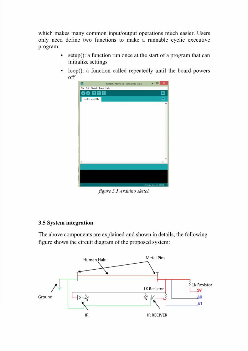
3.5 System integration
The above components are explained and shown in details, the following
figure shows the circuit diagram of the proposed system:
Human HairMetal Pins
Ground
IR IR RECIVER
1K Resistor
1K Resistor