
Chapter 3. Pulsed and water-cooled magnets
68
Ch. 3. Pulsed and Water‐Cooled Magnets T. J. Dolan Magnetic field calculations Coil forces Coil forces RLC circuit equations Distribution of J and B E t Energy storage Switching and transmission Magnetic flux compression Component reliability Power and cooling requirements Coil design considerations 1 Coil design considerations Dolan, IPR 2010
Transcript of Chapter 3. Pulsed and water-cooled magnets

Ch. 3. Pulsed and Water‐Cooled Magnets
T. J. Dolan
Magnetic field calculations Coil forcesCoil forces RLC circuit equations Distribution of J and BE tEnergy storage Switching and transmissionMagnetic flux compression Component reliability Power and cooling requirements Coil design considerations
1
Coil design considerations
Dolan, IPR 2010

BackgroundChinese Discovered magnetism and invented compass.
Mapped the world using compass and astronomical navigation.Zheng He brought knowledge to Europe in 1434
Oersted deflection of compass by current in wire
Ampere interaction of current carrying wiresAmpere interaction of current-carrying wires
Faraday magnetic induction
Maxwell equations of electromagnetism
Dolan, IPR 2010 2
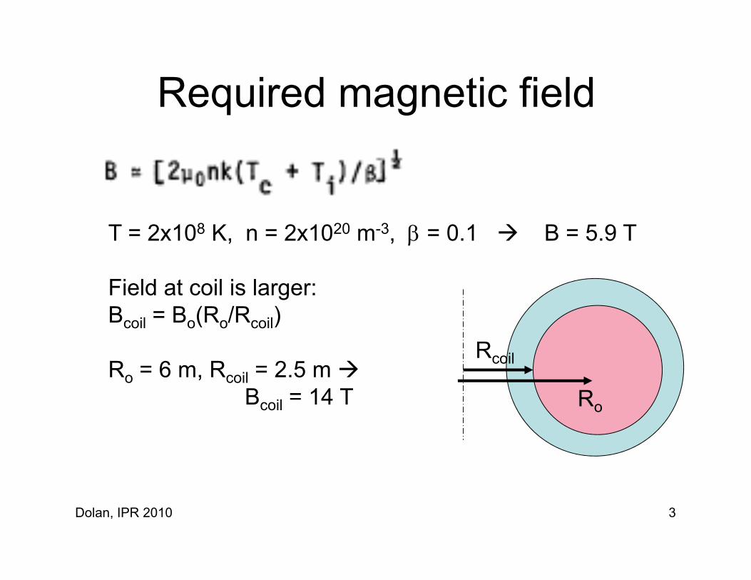
Required magnetic fieldequ ed ag e c e d
T = 2x10⁸ K, n = 2x10²⁰ m-3, = 0.1 B = 5.9 T
Field at coil is larger: Bcoil = Bo(Ro/Rcoil) coil o( o coil)
Ro = 6 m, Rcoil = 2.5 m B il = 14 T
Rcoil
RBcoil 14 T Ro
Dolan, IPR 2010 3

Advantages of Water-Cooled MagnetsAdvantages of Water Cooled Magnets
Dolan, IPR 2010 4

Dolan, IPR 2010 5
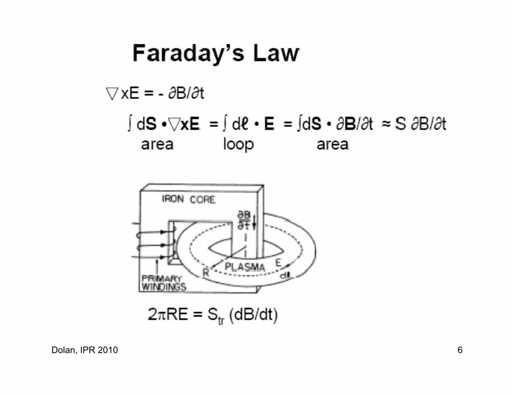
Dolan, IPR 2010 6

Dolan, IPR 2010 7

(eh and fg are equal and opposite.)
Dolan, IPR 2010 8

Dolan, IPR 2010 9

Toroidal Magnetic Field RippleToroidal Magnetic Field Ripple
Dolan, IPR 2010 10
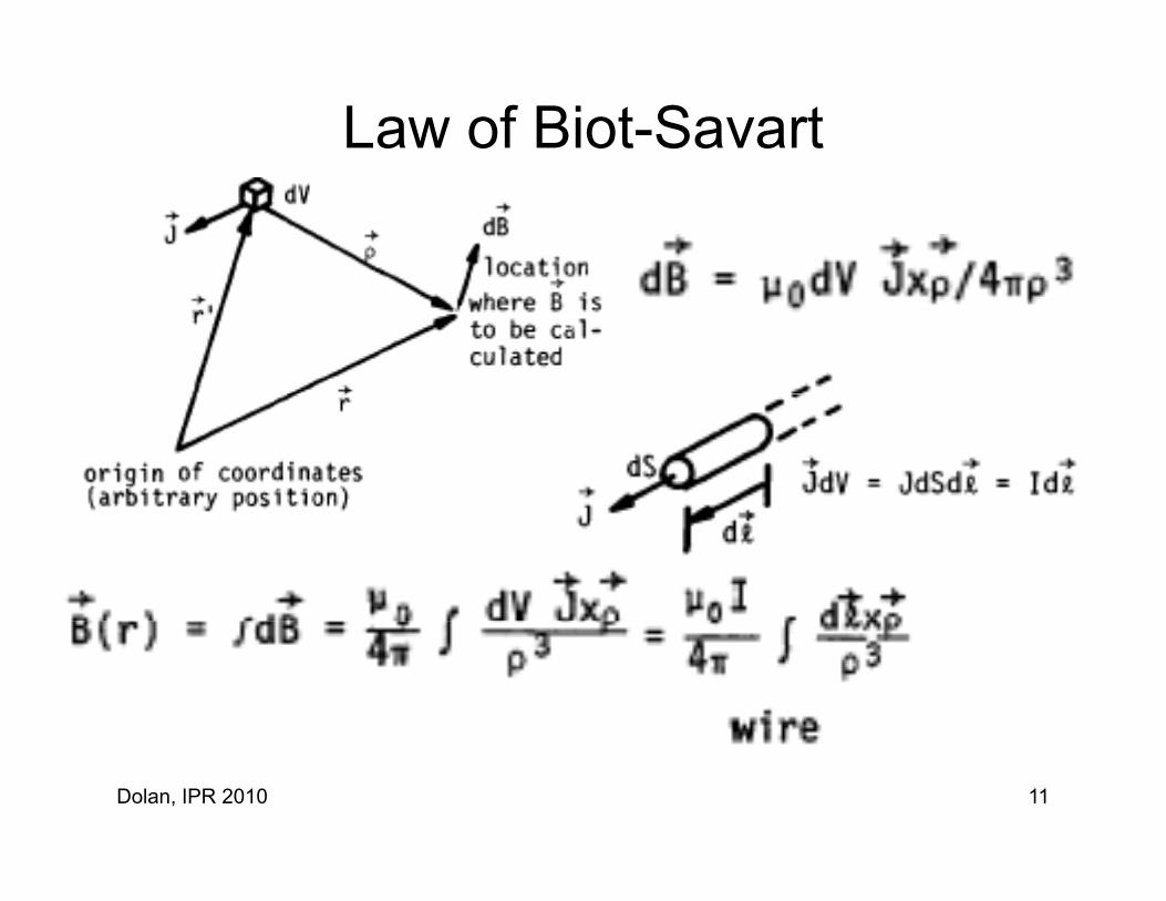
Law of Biot-Savart
Dolan, IPR 2010 11
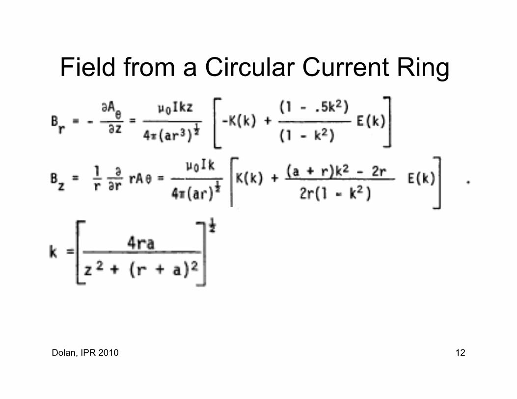
Field from a Circular Current RingField from a Circular Current Ring
Dolan, IPR 2010 12

Dolan, IPR 2010 13
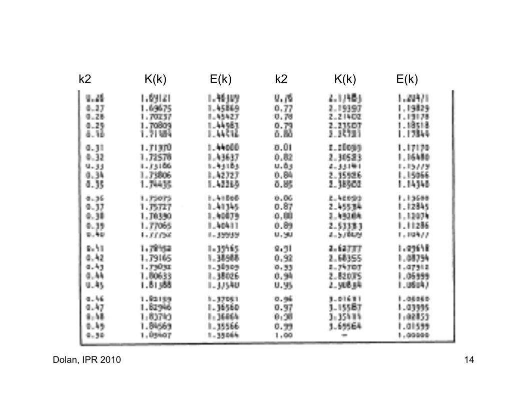
k2 K(k) E(k) k2 K(k) E(k)k2 K(k) E(k) k2 K(k) E(k)
Dolan, IPR 2010 14

Example – Field of Circular CoilCircular coil, a = 0.5 m, I = 100 kA. Find B( r = 0.4 m, z = 0.6 m )
k2 = 0.683707K(k) = 2.05215 E(k) = 1.25125
Br = 0.0025 T
Bz = 0.027 T
Dolan, IPR 2010 15
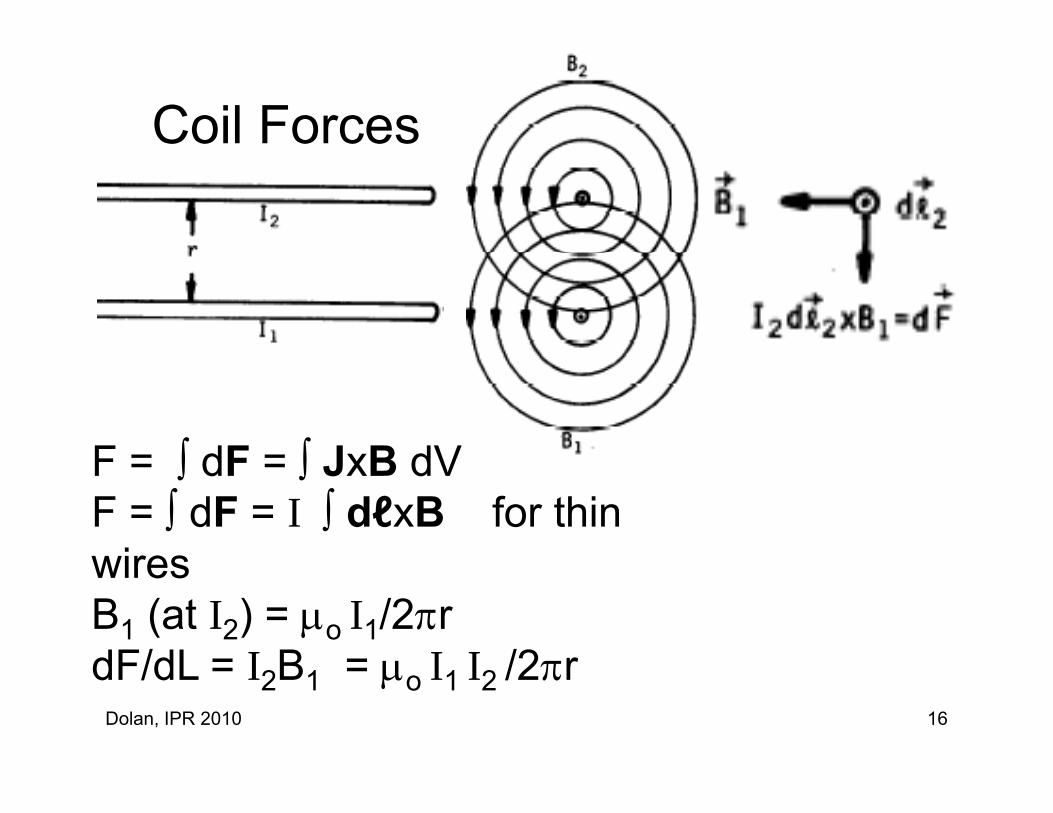
Coil Forces
F = dF = JxB dVF = dF = JxB dV F = dF = I dℓxB for thin wireswiresB1 (at I2) = o I1/2rdF/dL = I B = I I /2r
Dolan, IPR 2010 16
dF/dL = I2B1 = o I1 I2 /2r
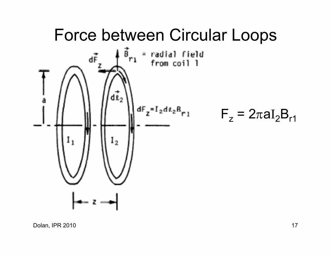
Force between Circular Loops
F 2 aI BFz = 2aI2Br1
Dolan, IPR 2010 17
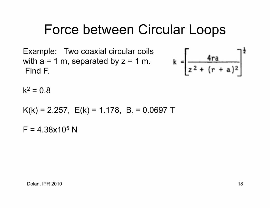
Force between Circular LoopsExample: Two coaxial circular coilswith a = 1 m, separated by z = 1 m. , p yFind F.
k2 = 0 8k = 0.8
K(k) = 2.257, E(k) = 1.178, Br = 0.0697 T
F = 4.38x10⁵ N
Dolan, IPR 2010 18

Tensile Stress in Long Solenoid Coil
Example Case:Example Case: r1 = 1 m, ∆r = 0.2 mB = 10 T.
= 212 MPa
Yield stress of copper= 280 MPa
Dolan, IPR 2010 19

Force on Torsatron CoilsForce on Torsatron Coils
Dolan, IPR 2010 20

Force Reduced Torsatron Coils
Optimum Pitch angle ~ 42ogR/ac ~ 7
Dolan, IPR 2010 21

TF Coil Design ConsiderationsgTF coil forces tend to:
i il diincrease coil radius acdecrease major radius Rcbend coils (due to interaction with vertical field)
Considerstress concentrationsfatiguefatiguecreepthermal stress
TF coils shaped like “D” have lower stress than circular coilsTF coils shaped like “D” have lower stress than circular coils.
Dolan, IPR 2010 22

Reduction of Field Errors
Coil winding accuracy
Coil alignment
Coil supports to minimize motion
Series connection to equalize currentsSeries connection to equalize currents
Stray B fields from current leads
Stray B fields from ferrous objects
Dolan, IPR 2010 23
Componentsp
Energy storageEnergy storage
Switches
Transmission lines
Coils
Diagnostics and controlsDiagnostics and controls
Dolan, IPR 2010 24
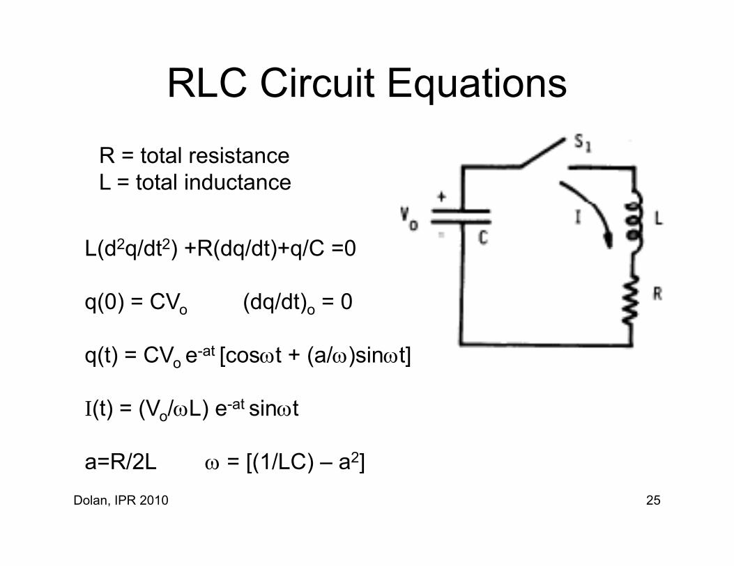
RLC Circuit EquationsqR = total resistanceL t t l i d tL = total inductance
L(d2q/dt2) +R(dq/dt)+q/C =0L(d2q/dt2) +R(dq/dt)+q/C =0
q(0) = CVo (dq/dt)o = 0
q(t) = CVo e-at [cost + (a/)sint]
I(t) = (Vo/L) e-at sint
a=R/2L = [(1/LC) a2]Dolan, IPR 2010 25
a=R/2L = [(1/LC) – a2]
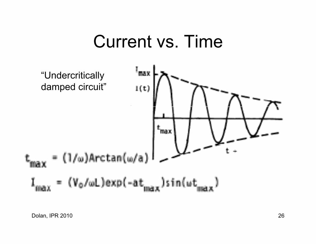
Current vs TimeCurrent vs. Time
“UndercriticallyUndercritically damped circuit”
Dolan, IPR 2010 26

“Crowbar” Switch S2
Close S1 at t=0
Close S2 at t=tmax
Dolan, IPR 2010 27

Resistance of Wire, Rod, Plate, TubeResistance of Wire, Rod, Plate, Tubeℓ
R d / SR = dx / S0
Example:Copper tube r1 = 0.02 m, r2 = 0.025 m, ℓ = 3 m= 2x10⁻⁶ Ohm-m 2x10 Ohm m
S = (r22-r1
2) = 0.000707 m2
R = ℓ / S = 0.00849 Ohm
Dolan, IPR 2010 28

Inductance of N-turn SolenoidInductance of N turn SolenoidLength ℓ , Radii r1 and r2
= r2/r11 2
Example: N=20,ℓ = 1 m r = 5 mℓ = 1 m, r1 = .5 m,r2 = .8 m
= 1.6, = 2, L/N2r1 = 1.2x10-6
= ℓ /r1
L = 2.4x10⁻⁴ Henry
Dolan, IPR 2010 29

Parallel Plate Transmission LineParallel Plate Transmission Line
L=oS ℓ Ksh / h
Dolan, IPR 2010 30

Graph of K h vs (s/h)Graph of Ksh vs. (s/h)
If /h 1If s/h << 1,
then Ksh = 1
Dolan, IPR 2010 31
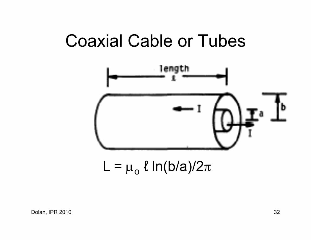
Coaxial Cable or TubesCoaxial Cable or Tubes
L = ℓ ln(b/a)/2L = o ℓ ln(b/a)/2
Dolan, IPR 2010 32

Distribution of J and BDistribution of J and B
J/t = 2J/J/t J/B/t = 2B/
Assume 2B ≈ B/2
B/t ≈ B
Then B ≈ B/2 ≈
Ski d th (2/ )1/2Skin depth = (2/)1/2
In copper at 1 MHz, = 0.07 mm
Dolan, IPR 2010 33
pp
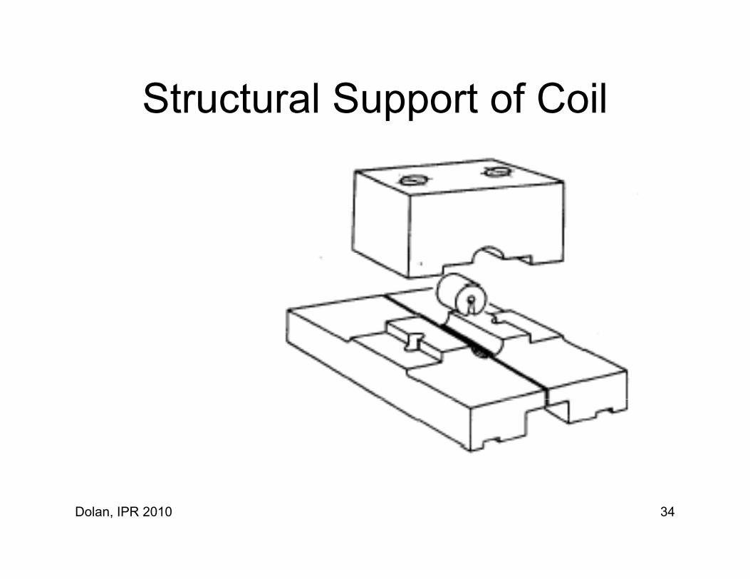
Structural Support of CoilStructural Support of Coil
Dolan, IPR 2010 34

Distribution of J and B in coilDistribution of J and B in coil
Actual
Approximate
Dolan, IPR 2010 35
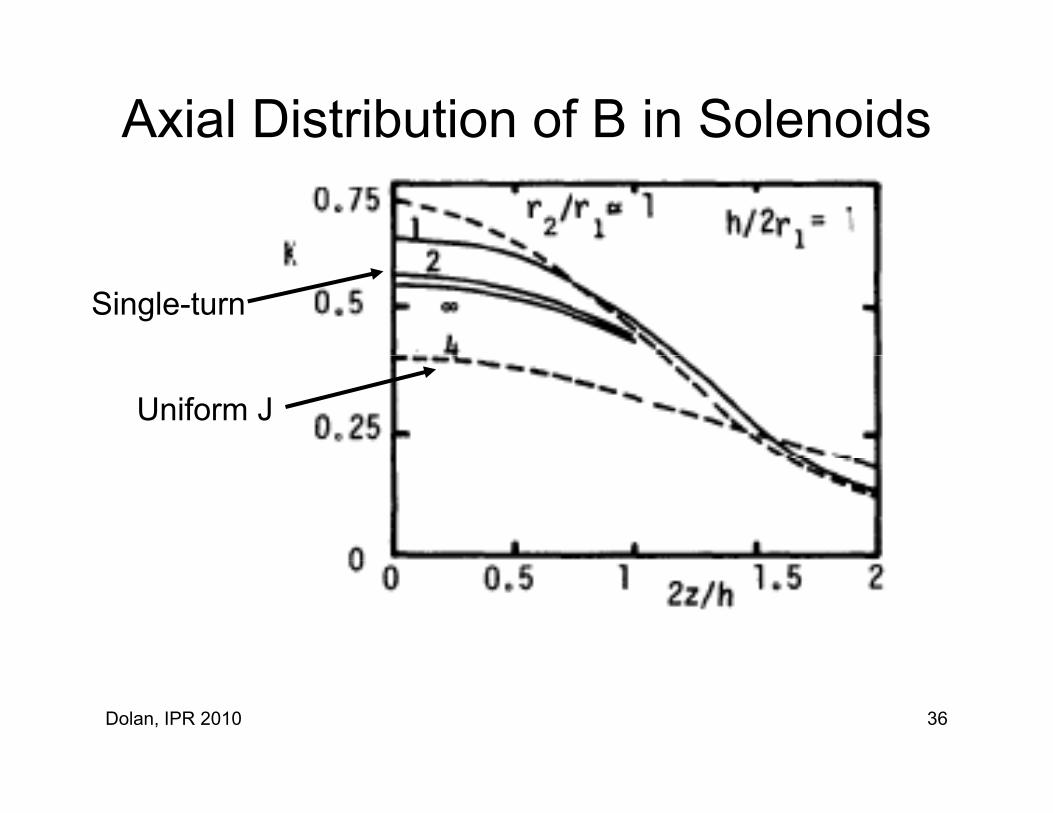
Axial Distribution of B in Solenoids
Single-turn
Uniform J
Dolan, IPR 2010 36
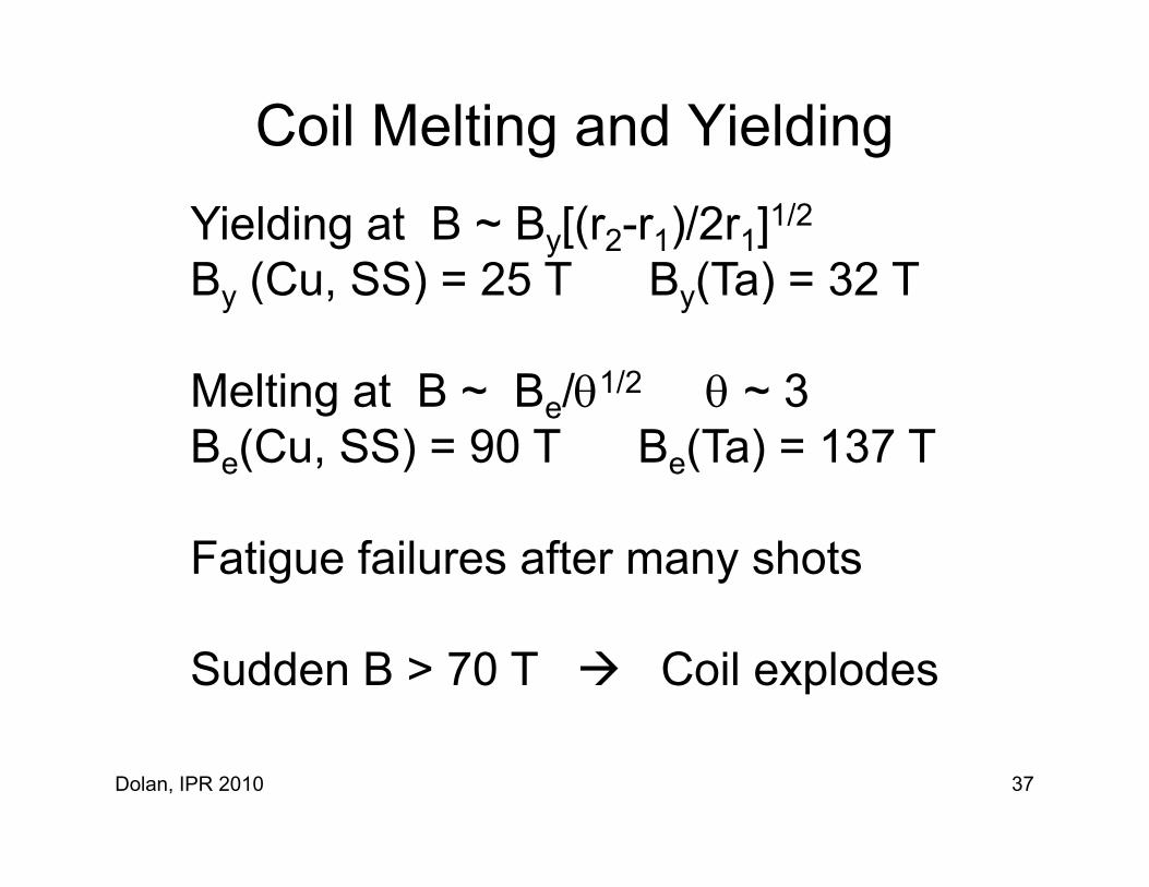
Coil Melting and YieldingYielding at B ~ By[(r2-r1)/2r1]1/2
B (Cu SS) = 25 T B (Ta) = 32 TBy (Cu, SS) = 25 T By(Ta) = 32 T
Melting at B ~ B /1/2 ~ 3Melting at B ~ Be/1/2 ~ 3 Be(Cu, SS) = 90 T Be(Ta) = 137 T
Fatigue failures after many shots
Sudden B > 70 T Coil explodes
Dolan, IPR 2010 37

Energy Storage Systems
Dolan, IPR 2010 38

Scyllac CapacitorScyllac Capacitor
60 kV, 1.85 F
Dolan, IPR 2010 39

Energy Storage System CostsEnergy Storage System Costs
Fusion experimentsPower gridsS lSolar powerWind power
flywheel
~1980 values
Dolan, IPR 2010 40

Inductive Energy Storage
Opening switch S1 forces current to flow throughplasma confinement coil.
S1 : difficult to prevent arcing
Transfer efficiency = LsL/(Ls+L)2 25%
Dolan, IPR 2010 41
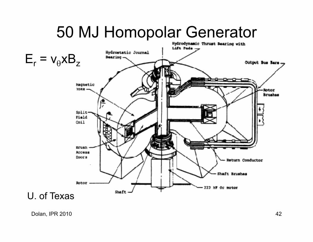
50 MJ Homopolar GeneratorEr = vxBz
U of Texas
Dolan, IPR 2010 42
U. of Texas
Flywheel Energy Storage
Can store about 500 MJ/m3Can store about 500 MJ/m
Princeton Plasma Physics LaboratoryPrinceton Plasma Physics Laboratory
200 MW 3motor-generator 200 MW, 3 s
More expensive than homopolar system
Dolan, IPR 2010 43

Spark Gap Switchp p
Dolan, IPR 2010 44

Los Alamos Dual Spark Gap Switch
Low “jitter”:3240 switchesfired within 10 ns.
Dolan, IPR 2010 45

Exploding Foil Switch
Dolan, IPR 2010 46

Marx Bank
+400 kV
Capacitors are charged in parallel
100 kV 100 kV 100 kV 100 kV
Capacitors are charged in parallelThen discharged in series to give high voltage
Dolan, IPR 2010 47

High Voltage Coaxial Cable
Scyllac experiment had 250 km of these cablesScyllac experiment had 250 km of these cables. 105 shot reliability.
Dolan, IPR 2010 48

Magnetic Flux Compression
“Bellows” type
Dolan, IPR 2010 49

Imploding Metallic LinerImploding Metallic Linerexplosive
linerDebris
lowflux
Debris
Liner
Compressed
flux
Dolan, IPR 2010 50

Failure Ratesfjdt = failure probability of item j during dt
tFailure probability between 0 and t: p = dt f (t)Failure probability between 0 and t: pf = dt fj(t)
0
Probability of not failing before time t = 1 pProbability of not failing before time t = 1-pf
“Failure Rate” at time t: rj(t) = pf/(1-pf)
Total failure rate r(t) = rj(t) (failures per second)jj
Estimated time between failures ETBF = 1/r(t)
Dolan, IPR 2010 51
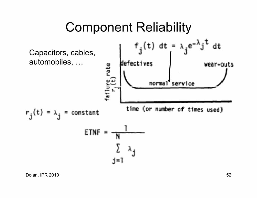
Component Reliability
Capacitors, cables,automobilesautomobiles, …
Dolan, IPR 2010 52
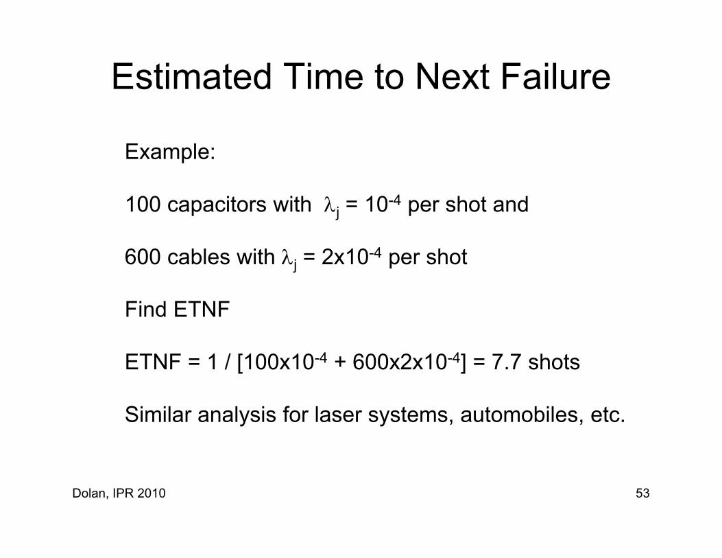
Estimated Time to Next Failure
Example:
100 capacitors with j = 10-4 per shot and
600 cables with j = 2x10⁻⁴ per shot
Find ETNFFind ETNF
ETNF = 1 / [100x10-4 + 600x2x10-4] = 7.7 shots
Similar analysis for laser systems, automobiles, etc.
Dolan, IPR 2010 53
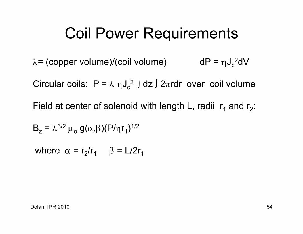
Coil Power Requirements
= (copper volume)/(coil volume) dP = Jc2dV
Circular coils: P = Jc2 dz 2rdr over coil volume
fField at center of solenoid with length L, radii r1 and r2:
Bz = 3/2 o g()(P/r1)1/2z o g( )( 1)
where = r2/r1 = L/2r1
Dolan, IPR 2010 54
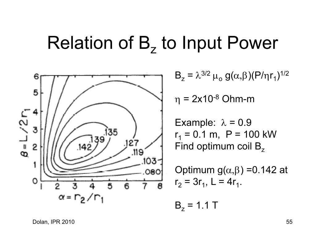
Relation of B to Input PowerRelation of Bz to Input PowerBz = 3/2 o g()(P/r1)1/2Bz o g()(P/r1)
= 2x10⁻⁸ Ohm-m
Example: = 0.9r1 = 0.1 m, P = 100 kW Find optimum coil Bz
Optimum g() =0.142 atOptimum g() 0.142 atr2 = 3r1, L = 4r1.
B = 1 1 TDolan, IPR 2010 55
Bz = 1.1 T

Coil Power RequirementsCoil Power Requirements
Given r1 = 3 m, B = 10 T, find P
Result: P = 240 MWResult: P 240 MW
This is why big experiments use superconducting coils.
Liquid N2 coolant (77 K) can lower and required power.
Dolan, IPR 2010 56

Heat Removal RateP =CmT(dV/dt)
C = specific heat of coolant = mass density of coolantm mass density of coolantT = temperature rise of coolantdV/dt = volumetric flow rate of coolant = AwvA l t h lAw = coolant channel areav = coolant flow speed
Dolan, IPR 2010 57

Pumping Powerp gReynold’s Number
Re = dVm/
p = f Lcmv2/2D (Pa)
Pumping power: Pc = p (dV/dt)/p p = pump efficiency
Dolan, IPR 2010 58

Friction F tFactor
Re = dVm/
Dolan, IPR 2010 59

Example – Pumping Power100 kW coil, 16 coolant channels in parallel, each 30 m long, 4.6 mm diameter, t = 60 K. Find dV/dt v p PFind dV/dt, v, p, Pc
Total dV/dt = P/CmT = 3.99x10⁻⁴ m3/s O h l (dV/d )/16 2 49 10 5 3/One channel = (dV/dt)/16 = 2.49x10⁻⁵ m3/sAc = 1.66x10⁻⁵ m2
v = (dV/dt)/A = 1.50 m/s( )Re = 6872 f = 0.035 from graphp = f L v2/2D = 2 56x105 Pap = f Lcmv /2D = 2.56x10 PaPc = p (dV/dt)/p = 128 W.
Dolan, IPR 2010 60
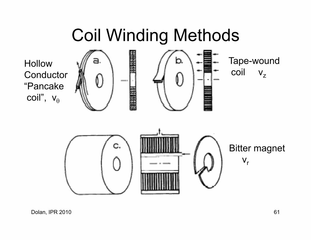
Coil Winding MethodsgHollow Conductor
Tape-wound coil vzConductor
“Pancake coil”, v
coil vz
Bitter magnetvr
Dolan, IPR 2010 61

Safe Value of Current DensitySafe Value of Current Density
Heat dissipated in volume Vch cooled by one channelPch = J2Vch
Equate to heat removed by coolant: P =Cmt(dV/dt)
Solve for safe value of J
Dolan, IPR 2010 62
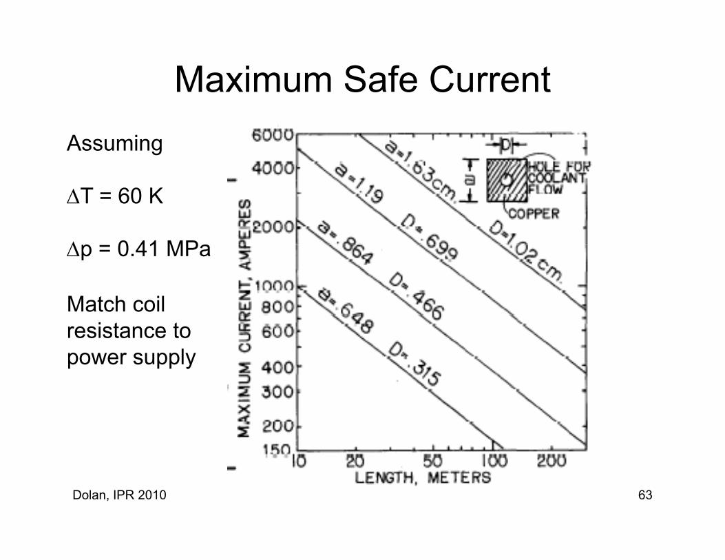
Maximum Safe CurrentAssuming
T = 60 K
p 0 41 MPap = 0.41 MPa
Match coilresistance topower supply
Dolan, IPR 2010 63

Coil Electrical ResistanceRc = Lc/AcExample: 16 coils in series,Example: 16 coils in series, each Lc = 30 m,Square copper with a = 8 64 mm D = 4 66 mm
Da = 8.64 mm, D = 4.66 mm.
Ac = a2 – D2/4 = 5.76x10⁻⁵ m2
a
One winding: Rc = 0.0104 Ohm16 in Series R = 1.67 Ohm.
Joints add resistance.
Dolan, IPR 2010 64

Coil WindingCoil WindingWind around a formHi h t i t b d t hHigh tension to bend copper to shapeAccurate position of copper important
Fiberglass insulation between layersEpoxy to hold conductor rigidlyBrazed jointsBrazed joints
Aluminum joints unreliable
Dolan, IPR 2010 65

Summary – Pulsed MagnetsSummary Pulsed MagnetsComponents and circuit calculations are simple, but
diff i f J d B ldiffusion of J and B are more complex.
Capacitor banks are widely used for pulsed magnetsy g
Inductive storage and flywheels less expensive atvery high energyvery high energy
Magnetic flux compression very high B
Component reliability for millions of shots is difficult
Dolan, IPR 2010 66

Summary – Water-Cooled Magnets
Cryogenic insulation refrigeration not neededCryogenic insulation, refrigeration not neededBrazed joints reliableBolted joints easy to assemble and disassembleC fCan tolerate high neutron fluencesDoes not require stabilizationTechnology well developed, reliablegy p ,
Calculations of current, B field, coil power,and pumping power simple and reliableand pumping power simple and reliable.
Dolan, IPR 2010 67

Dolan, IPR 2010 68