Chapter 3 Multiview Orthographic Projection.pptportal.unimap.edu.my/portal/page/portal30/Lecture...
52
PDT176 COMPUTER‐AIDED DRAFTING CHAPTER 3 CHAPTER 3 MULTIVIEW ORTHOGRAPHIC PROJECTION PROJECTION
Transcript of Chapter 3 Multiview Orthographic Projection.pptportal.unimap.edu.my/portal/page/portal30/Lecture...
PDT176 COMPUTER‐AIDED DRAFTING
CHAPTER 3CHAPTER 3
MULTIVIEW ORTHOGRAPHIC PROJECTIONPROJECTION
CONTENT
1) Projection Theory
2) Multiview Projection Plane) j
3) Orientation of Views
4) The Six Principal Views4) The Six Principal Views
5) Conventional View Placement
6) First- and Third-Angle Projection
7) Line Convention
8) Fundamental View of Edges & Planes
9) Angles on Planes
10) Holes
11) Tangent & Intersections
12) Orthographic Projection in AutoCAD
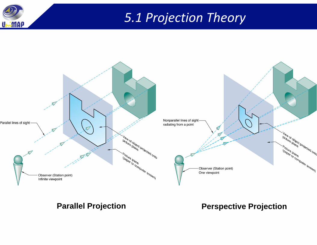
5.1 Projection Theory
To represent 3D objects on 2D media.o ep ese 3 objec s o ed a
Based on two variables:1 Line of sight – Imaginary ray of light between an observer’s eye1. Line of sight Imaginary ray of light between an observer s eye
and an object.2. Plane of projection – Imaginary flat plane upon which the image is
created by the lines of sight is projectedcreated by the lines of sight is projected.
Two projection methods primarily used; i) perspective and ii) parallel.
Parallel projection – Object is positioned at infinity and viewed from multiple points on an imaginary line, parallel to the object.
Perspective projection – Object is positioned at a finite distance and viewed from a single point. g p
5.1 Projection Theory
Parallel Projection Perspective Projection
5.2 Multiview Projection Plane
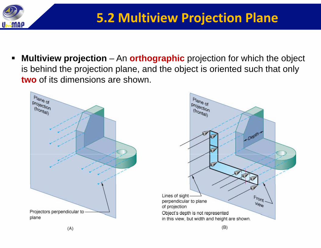
Multiview projection – An orthographic projection for which the object is behind the projection plane, and the object is oriented such that only two of its dimensions are shown.
5.2 Multiview Projection Plane
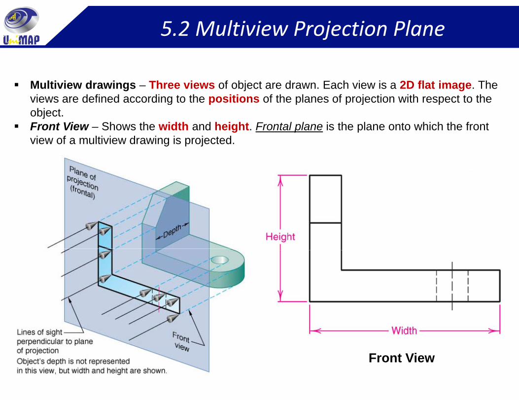
Multiview drawings – Three views of object are drawn. Each view is a 2D flat image. The views are defined according to the positions of the planes of projection with respect to the g p p p j pobject.Front View – Shows the width and height. Frontal plane is the plane onto which the front view of a multiview drawing is projected.
Front View
5.2 Multiview Projection Plane
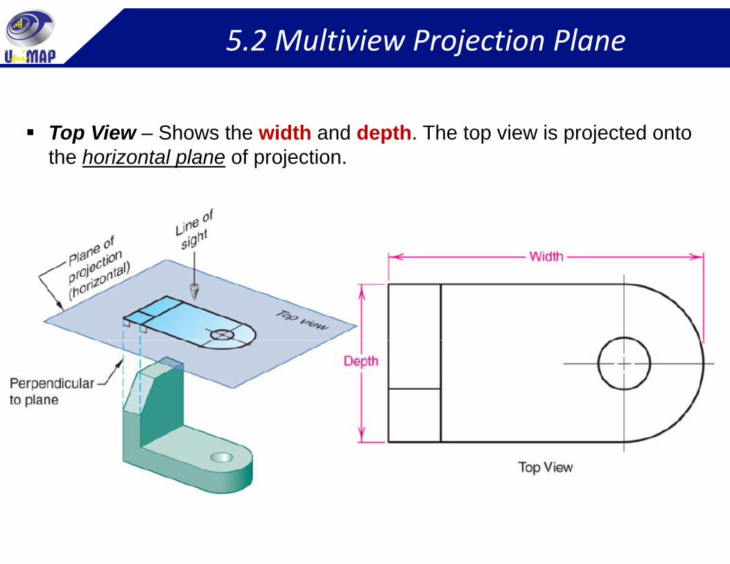
Top View – Shows the width and depth. The top view is projected onto the horizontal plane of projection.
5.2 Multiview Projection Plane
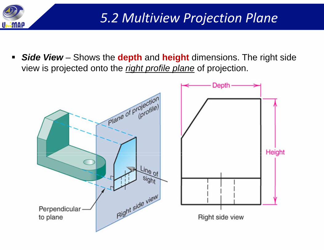
Side View – Shows the depth and height dimensions. The right side view is projected onto the right profile plane of projection.
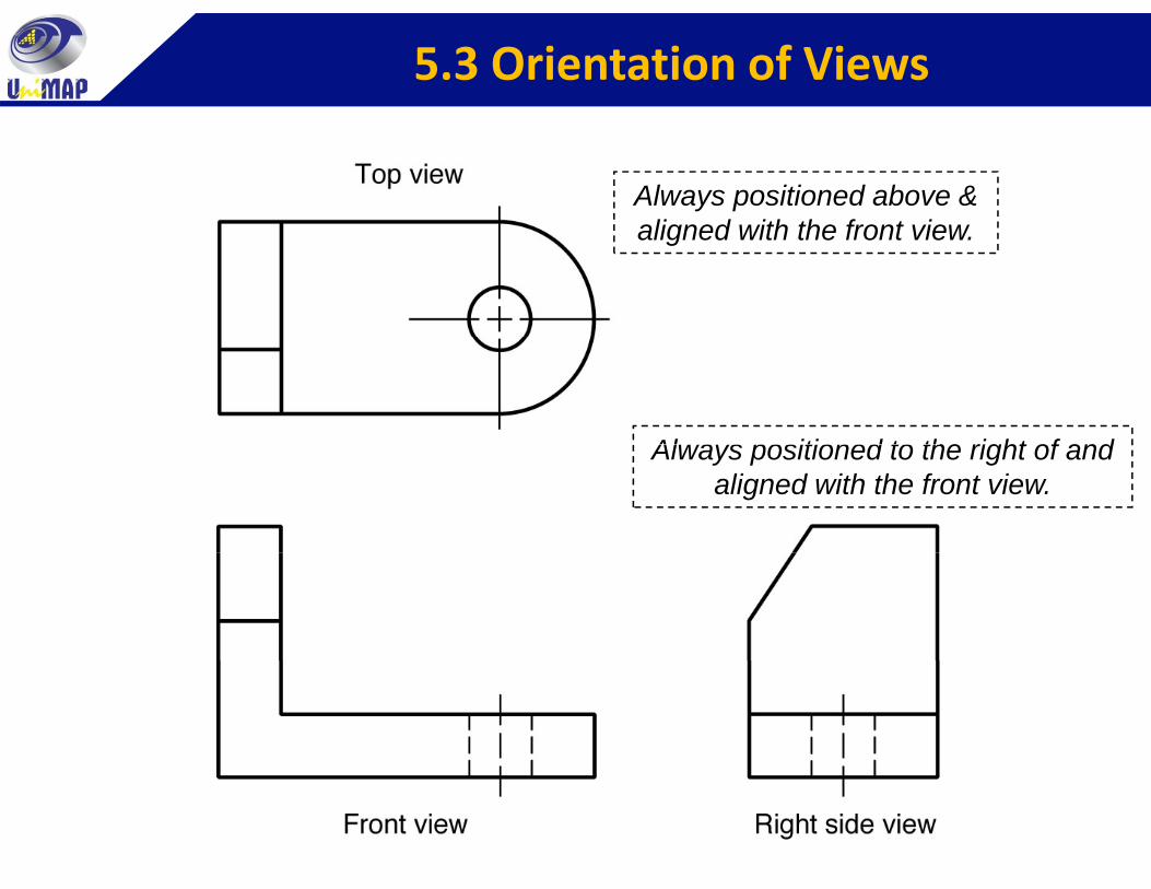
5.3 Orientation of Views
Always positioned above & aligned with the front viewaligned with the front view.
Always positioned to the right of andAlways positioned to the right of and aligned with the front view.
5.4 The Six Principal Views
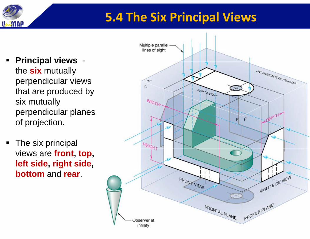
Principal views -Principal views the six mutually perpendicular views that are produced bythat are produced by six mutually perpendicular planes f j tiof projection.
The six principal views are front, top, left side, right side,bottom and rear.
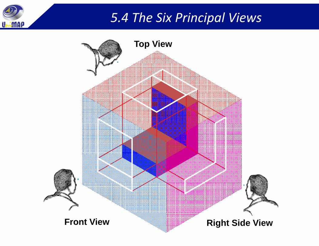
5.4 The Six Principal Views
Top View
Front View Right Side View
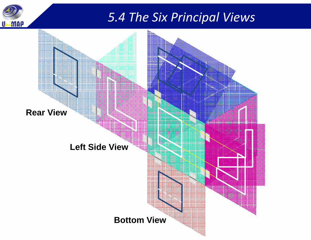
5.4 The Six Principal Views
Rear View
Left Side ViewLeft Side View
Bottom View
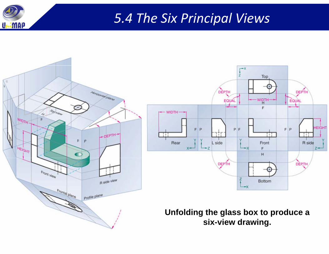
5.4 The Six Principal Views
Unfolding the glass box to produce a i i d isix-view drawing.
5.5 Conventional View Placement
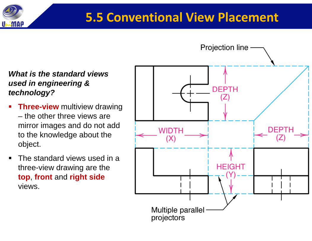
What is the standard views used in engineering & technology?technology?
Three-view multiview drawing – the other three views are mirror images and do not add to the knowledge about the object.
The standard views used in a three-view drawing are the top, front and right sidetop, front and right sideviews.
5.5 Conventional View Placement
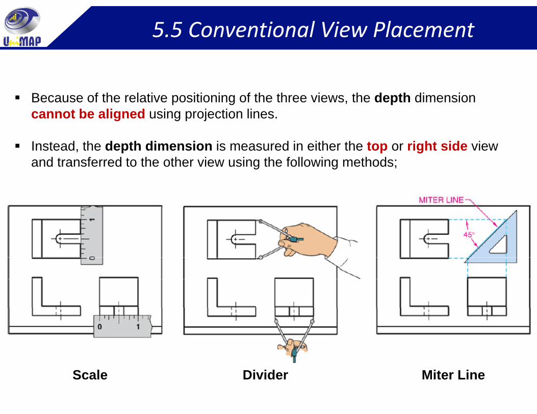
Because of the relative positioning of the three views, the depth dimension cannot be aligned using projection lines.
Instead, the depth dimension is measured in either the top or right side view f fand transferred to the other view using the following methods;
Scale Divider Miter Line
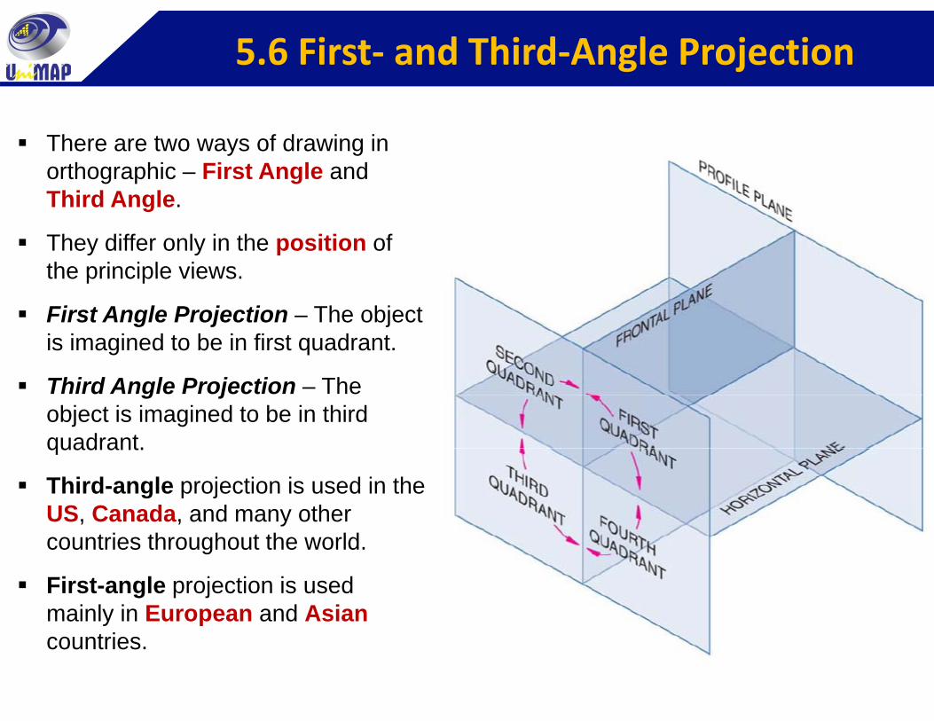
5.6 First‐ and Third‐Angle Projection
There are two ways of drawing in orthographic – First Angle and Third Angle.
They differ only in the position of the principle viewsthe principle views.
First Angle Projection – The object is imagined to be in first quadrant.
Third Angle Projection – The object is imagined to be in third quadrant.quadrant.
Third-angle projection is used in the US, Canada, and many other
t i th h t th ldcountries throughout the world.
First-angle projection is used mainly in European and Asiany pcountries.
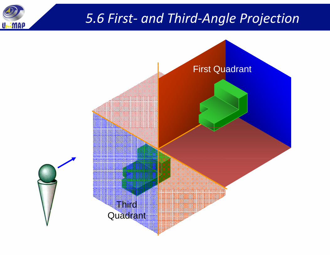
5.6 First‐ and Third‐Angle Projection
Fi Q dFirst Quadrant
ThirdQuadrant
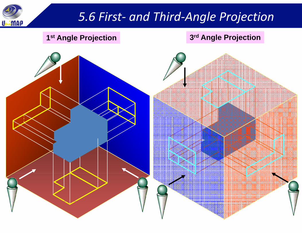
5.6 First‐ and Third‐Angle Projection
1st Angle Projection 3rd Angle Projection
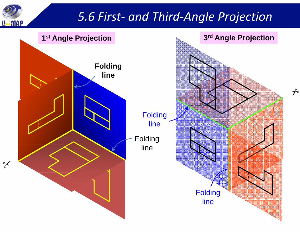
5.6 First‐ and Third‐Angle Projection
1st Angle Projection 3rd Angle Projection
Foldingline
Folding
Folding
Foldingline
line
Foldinglineline
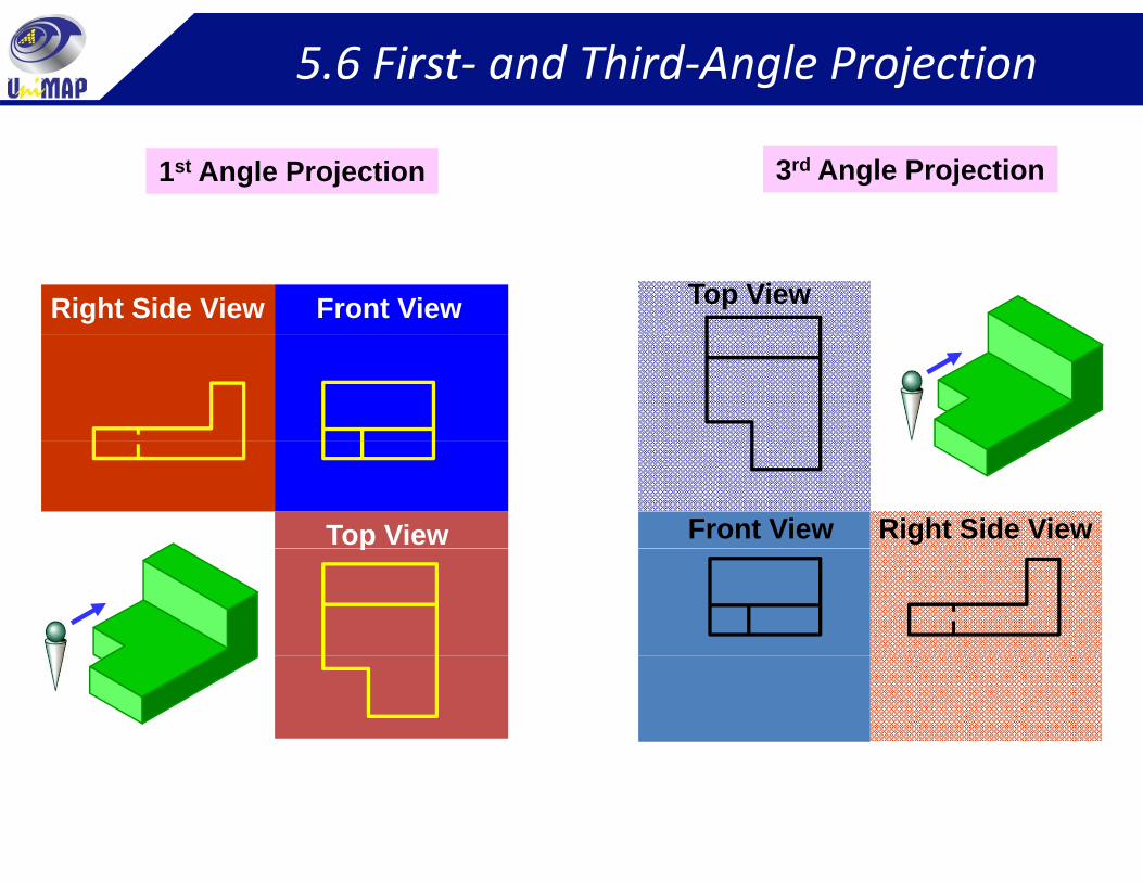
5.6 First‐ and Third‐Angle Projection
1st Angle Projection 3rd Angle Projection
Front ViewRight Side View Top View
Front View Right Side ViewTop Viewp
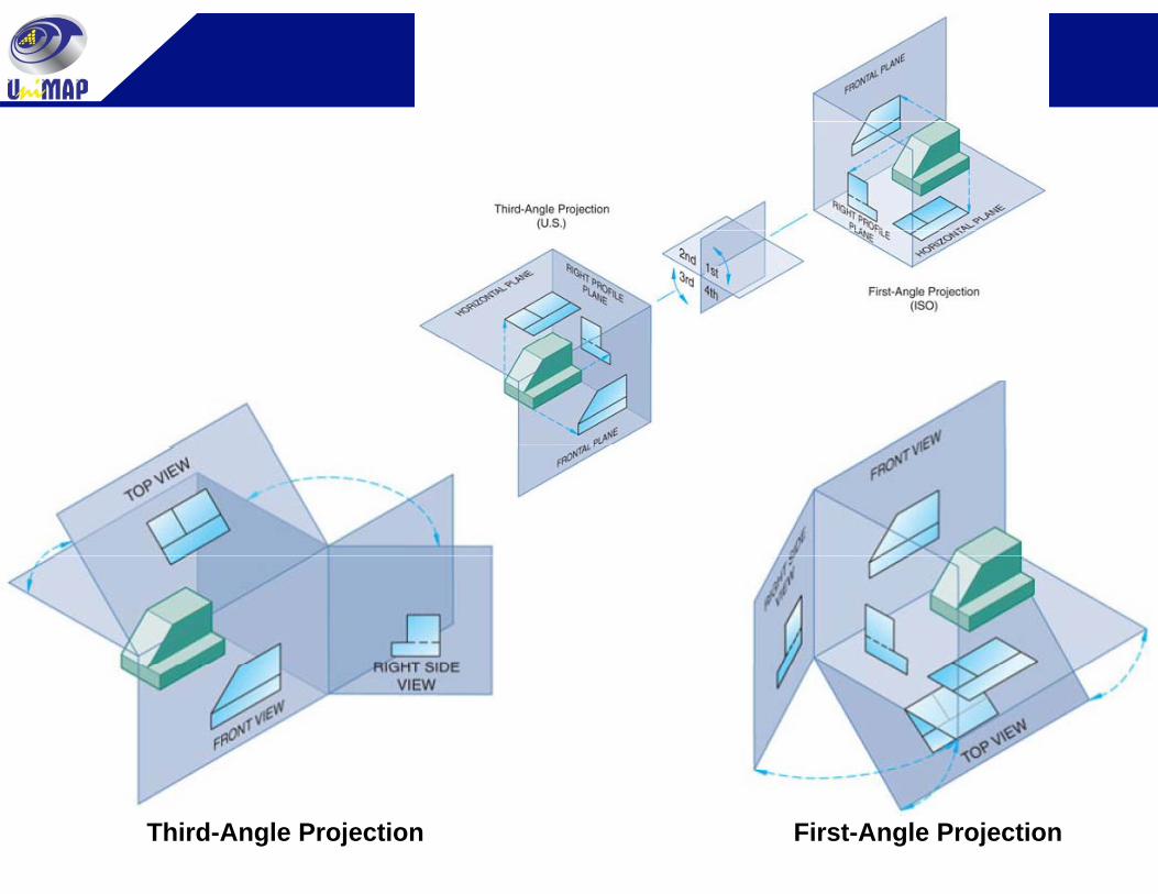
First‐ and Third‐Angle Projection contProjection cont.
Third-Angle Projection First-Angle Projection
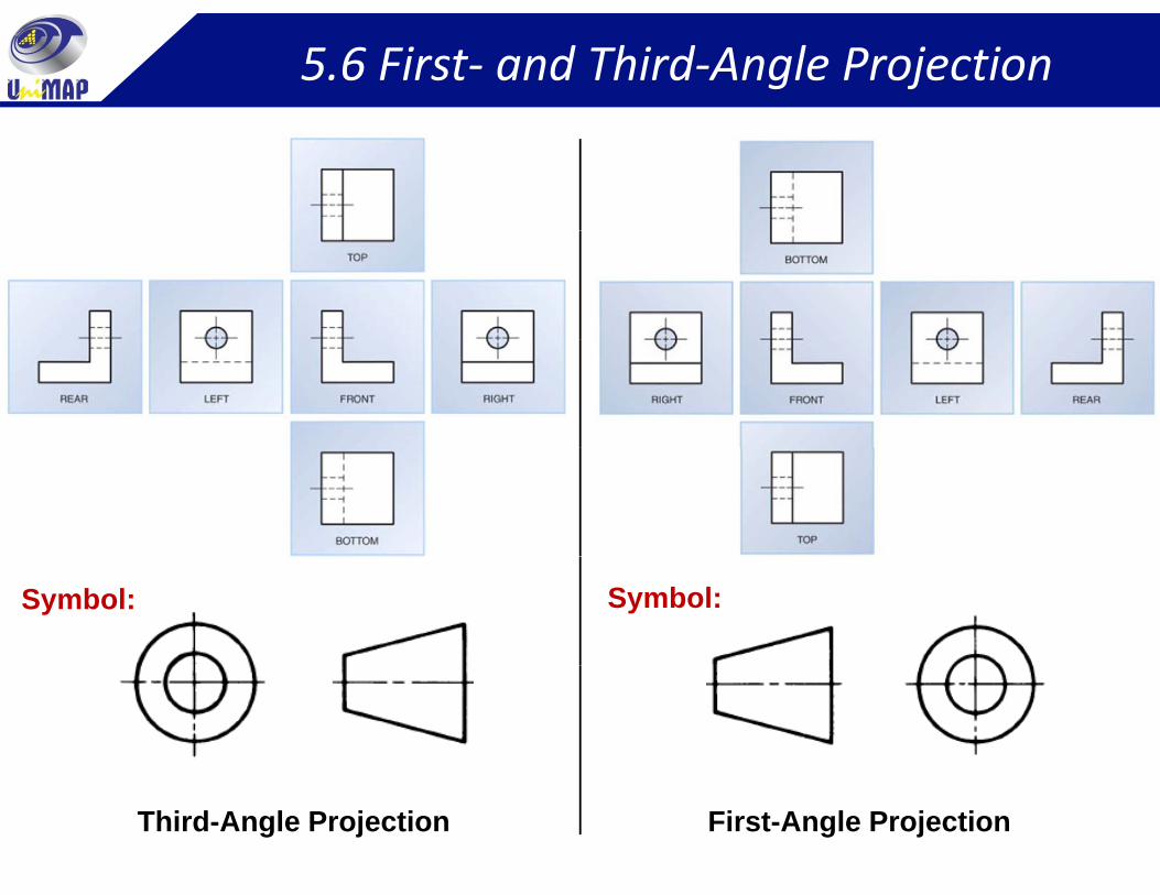
5.6 First‐ and Third‐Angle Projection
Symbol: Symbol:
Third-Angle Projection First-Angle Projection
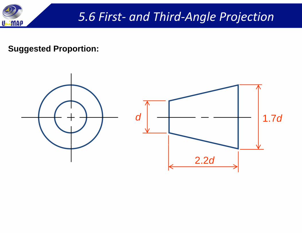
5.6 First‐ and Third‐Angle Projection
Suggested Proportion:
d 1 7dd 1.7d
2.2d
5.7 Line Convention
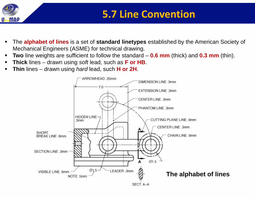
The alphabet of lines is a set of standard linetypes established by the American Society of Mechanical Engineers (ASME) for technical drawing.g ( ) gTwo line weights are sufficient to follow the standard – 0.6 mm (thick) and 0.3 mm (thin).Thick lines – drawn using soft lead, such as F or HB.Thin lines – drawn using hard lead, such H or 2H.
The alphabet of lines
5.7 Line Convention
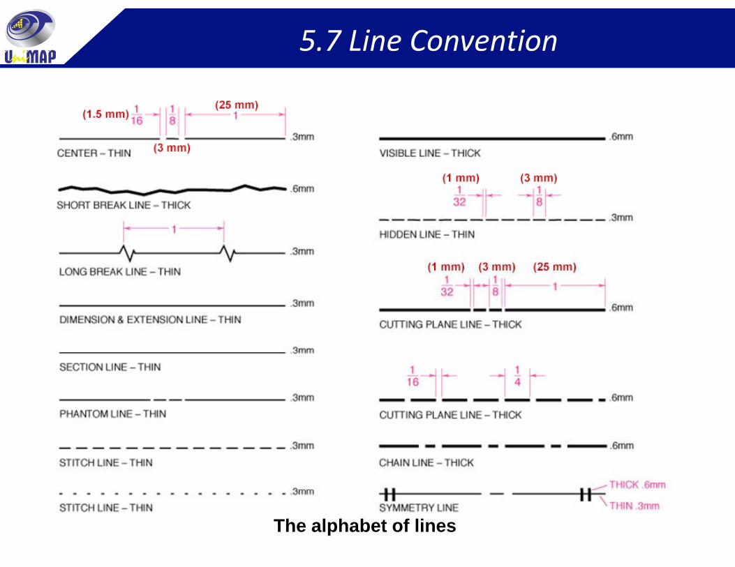
The alphabet of lines
5.7 Line Convention
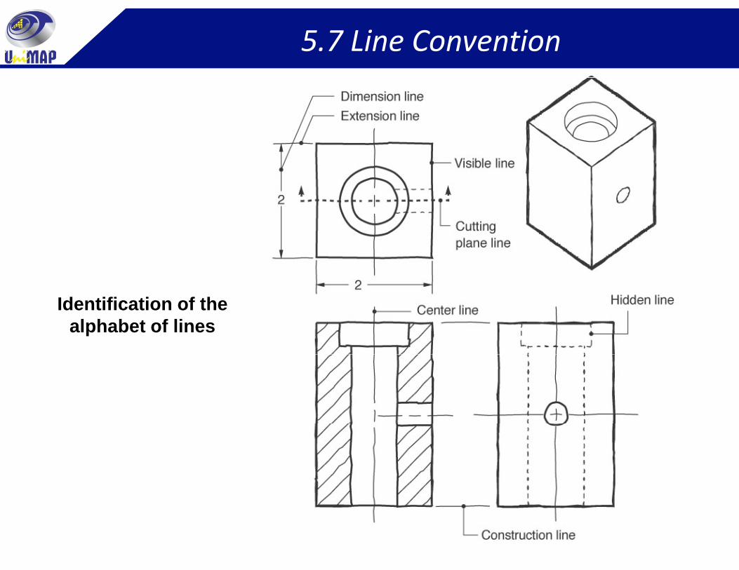
Identification of the alphabet of lines
5.7 Line Convention
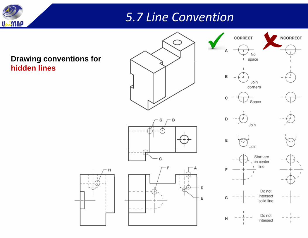
Drawing conventions forDrawing conventions for hidden lines
5.7 Line Convention
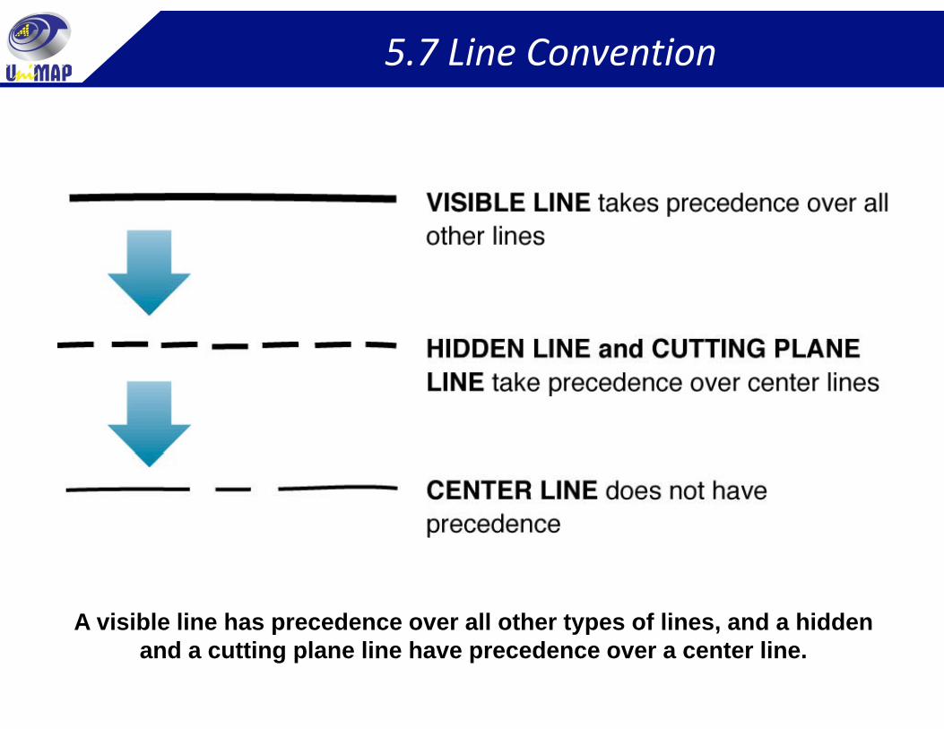
A visible line has precedence over all other types of lines, and a hidden p yp ,and a cutting plane line have precedence over a center line.
5.7 Line Convention
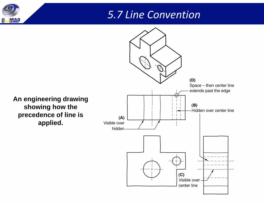
An engineering drawing g g gshowing how the
precedence of line is applied.
5.7 Line Convention
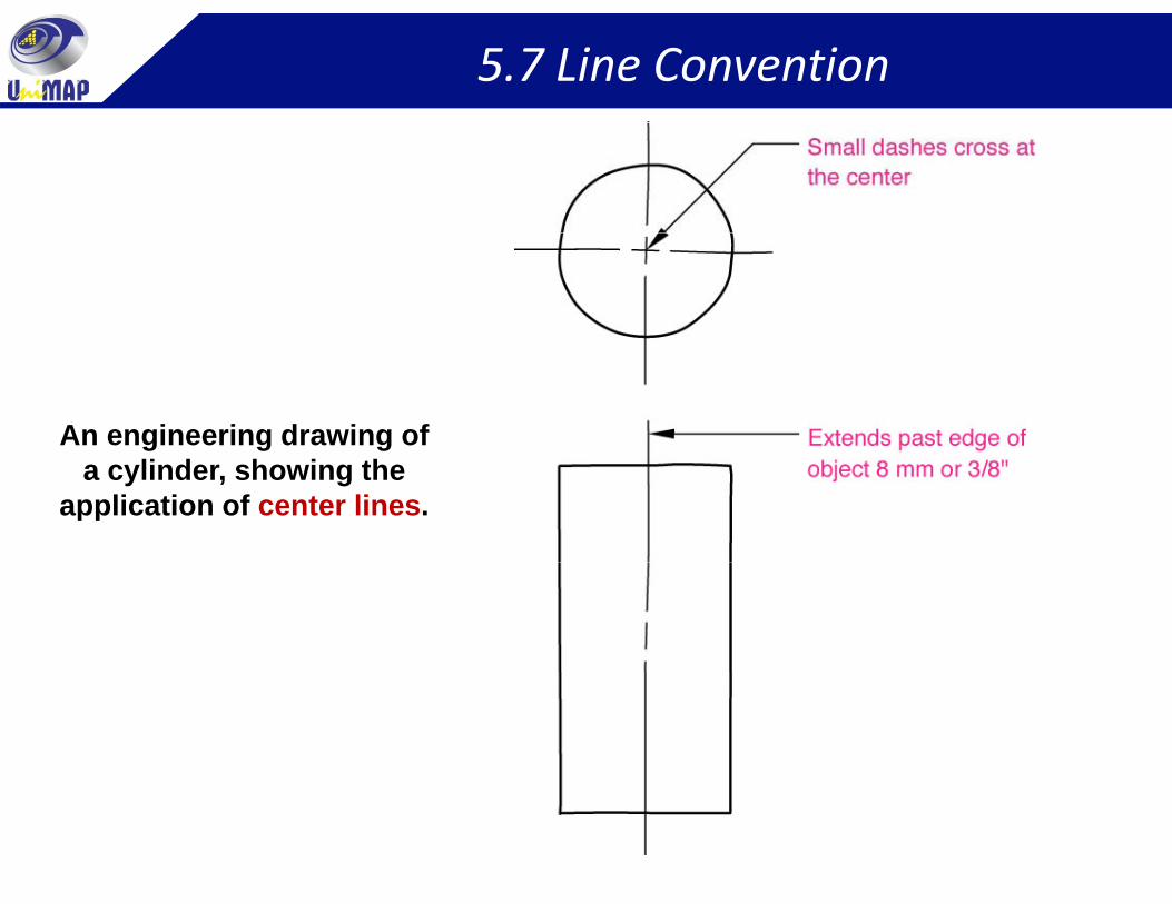
An engineering drawing of a cylinder, showing the
application of center lines.
5.8 Fundamental View of Edges & Planes
1) Edge Line
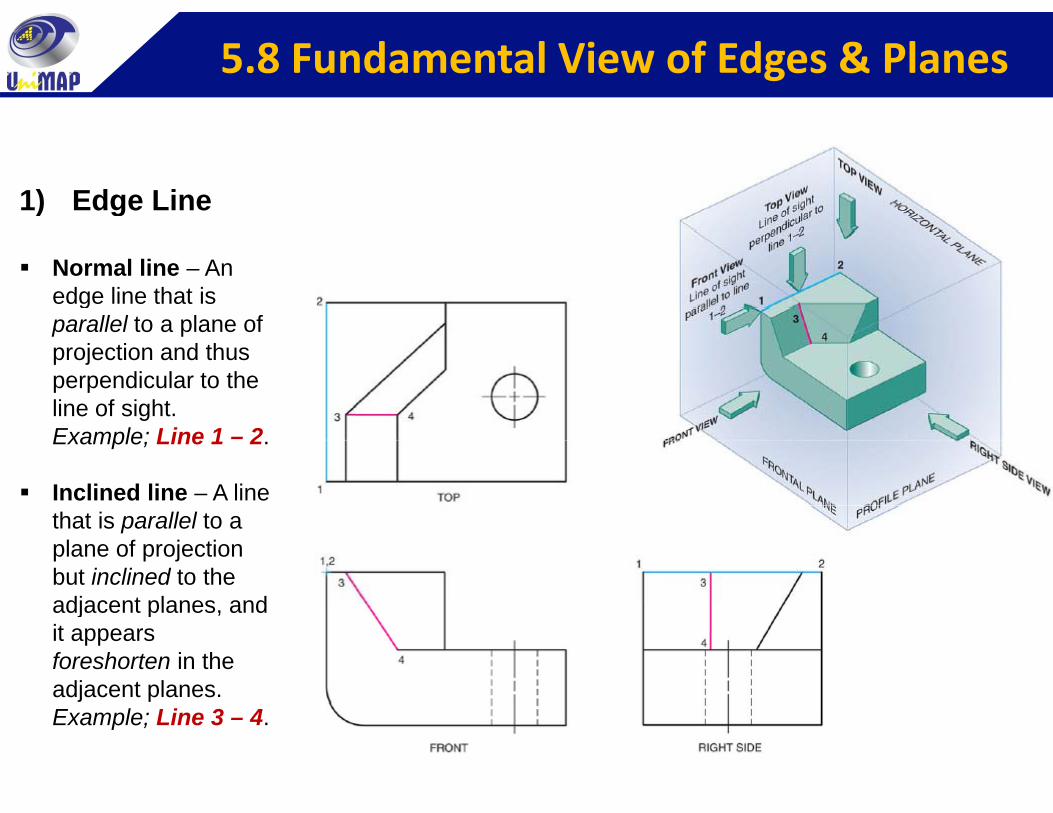
Normal line – An edge line that is
1) Edge Line
gparallel to a plane of projection and thus perpendicular to the line of sightline of sight. Example; Line 1 – 2.
Inclined line – A line that is parallel to a plane of projection but inclined to the adjacent planes andadjacent planes, and it appears foreshorten in the adjacent planes. Example; Line 3 – 4.
5.8 Fundamental View of Edges & Planes
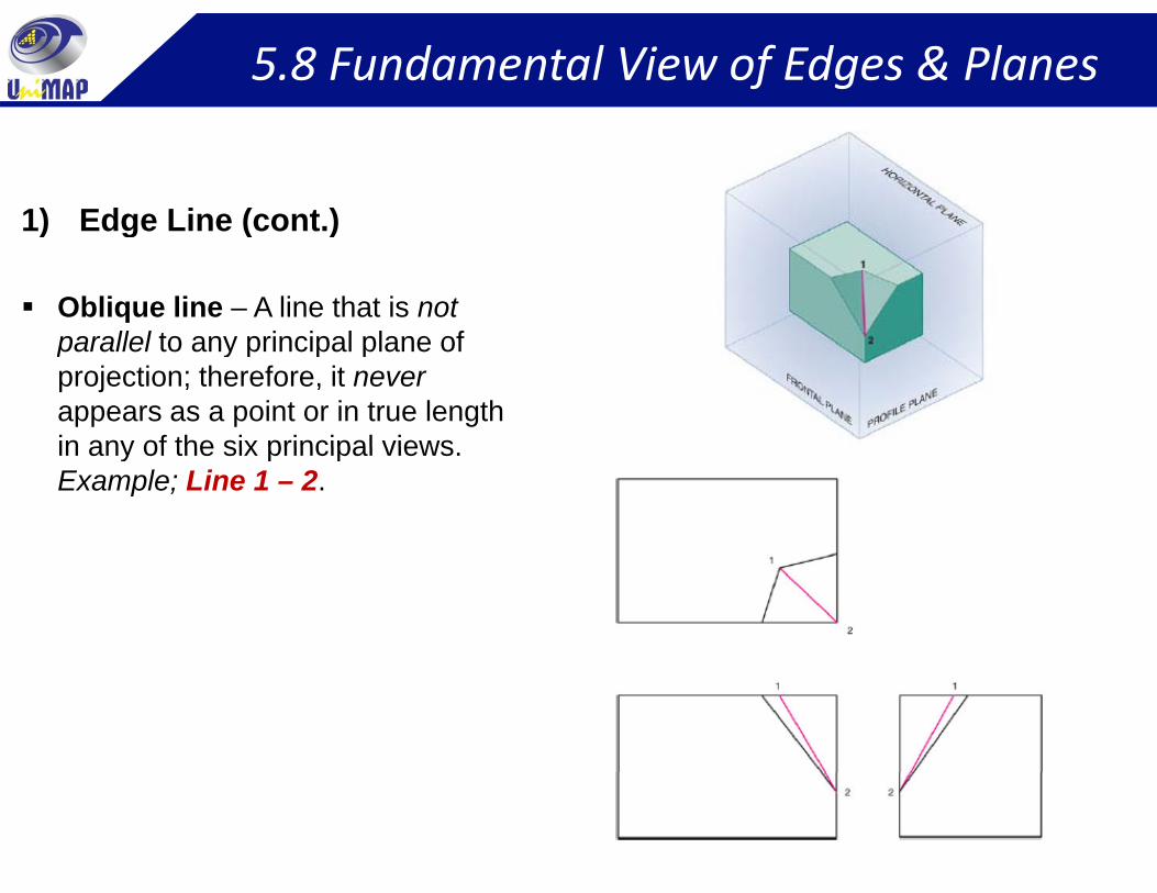
1) Edge Line (cont.)
Oblique line – A line that is not parallel to any principal plane of
1) Edge Line (cont.)
parallel to any principal plane of projection; therefore, it neverappears as a point or in true length in any of the six principal viewsin any of the six principal views. Example; Line 1 – 2.
5.8 Fundamental View of Edges & Planes
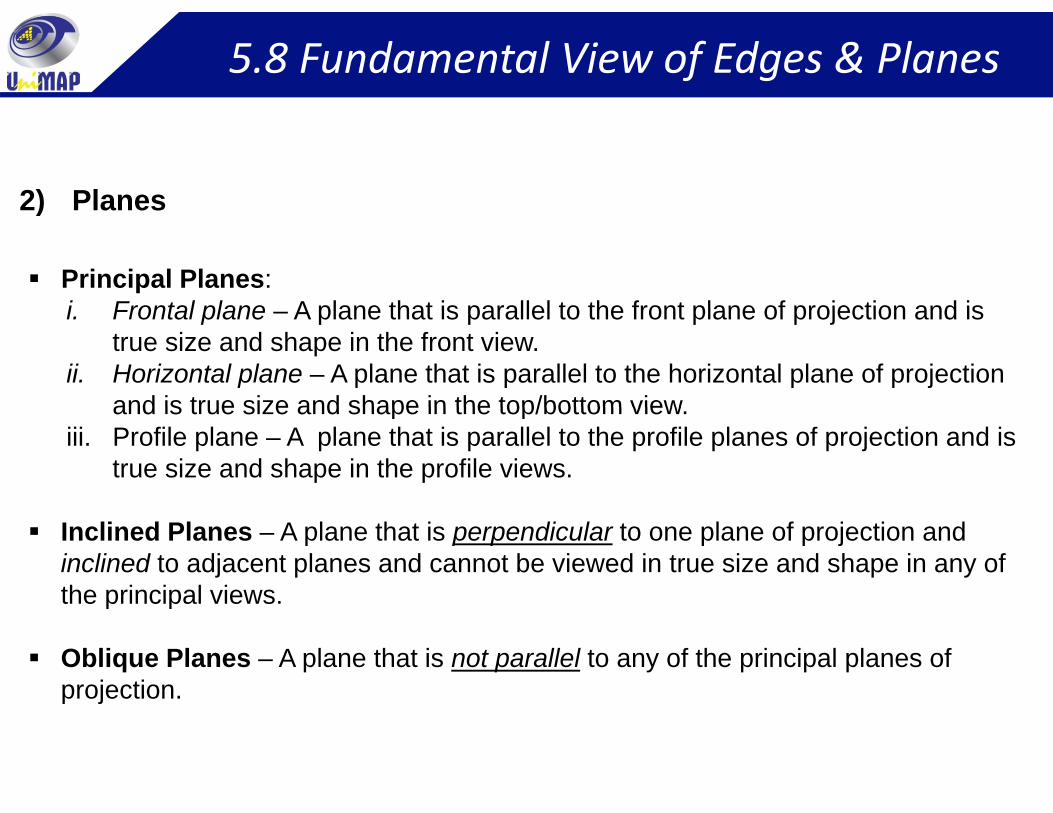
2) Planes2) Planes
Principal Planes:i Frontal plane A plane that is parallel to the front plane of projection and isi. Frontal plane – A plane that is parallel to the front plane of projection and is
true size and shape in the front view.ii. Horizontal plane – A plane that is parallel to the horizontal plane of projection
and is true size and shape in the top/bottom viewand is true size and shape in the top/bottom view.iii. Profile plane – A plane that is parallel to the profile planes of projection and is
true size and shape in the profile views.
Inclined Planes – A plane that is perpendicular to one plane of projection and inclined to adjacent planes and cannot be viewed in true size and shape in any of the principal views.p p
Oblique Planes – A plane that is not parallel to any of the principal planes of projection. p j
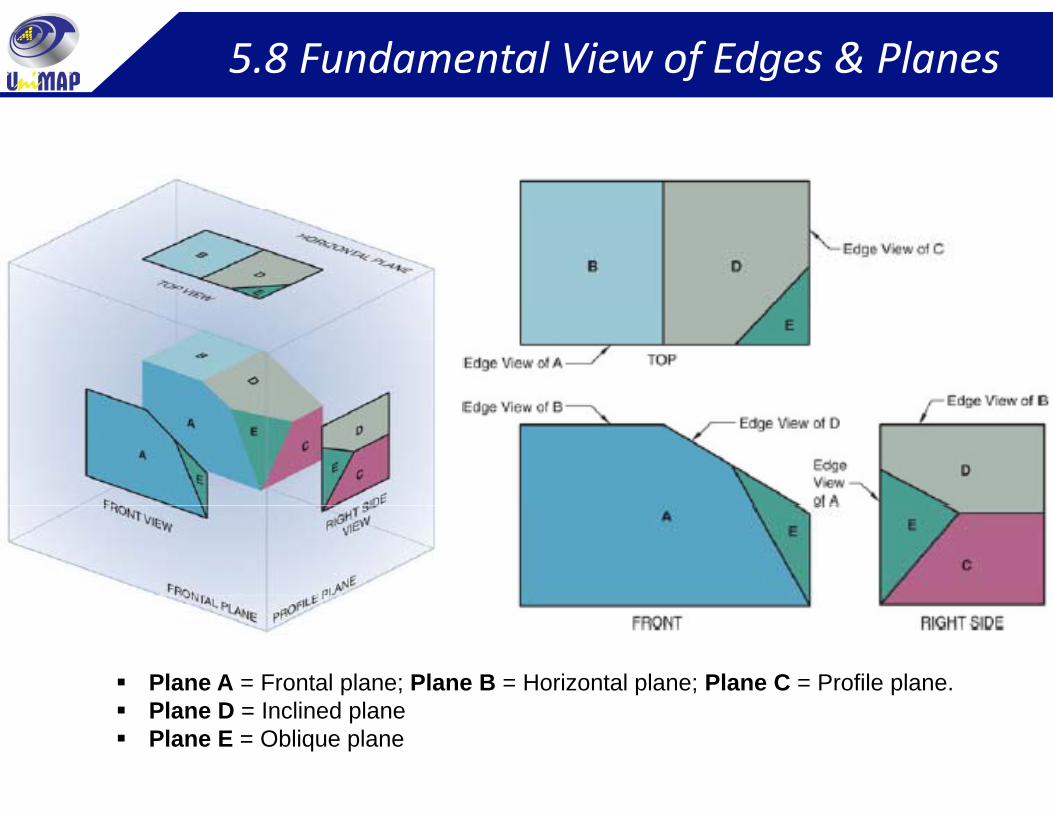
5.8 Fundamental View of Edges & Planes
Plane A = Frontal plane; Plane B = Horizontal plane; Plane C = Profile plane.Pl D I li d lPlane D = Inclined planePlane E = Oblique plane
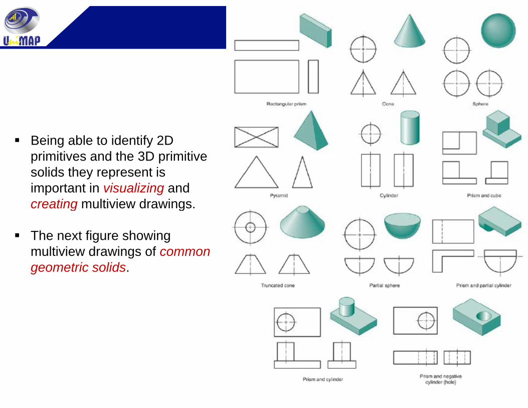
Multiview Representation
Being able to identify 2D primitives and the 3D primitiveprimitives and the 3D primitive solids they represent is important in visualizing and creating multiview drawingscreating multiview drawings.
The next figure showing multiview drawings of commonmultiview drawings of common geometric solids.
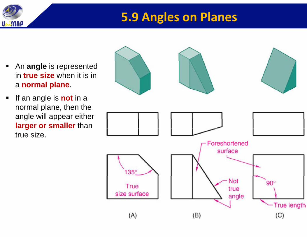
5.9 Angles on Planes
An angle is represented in true size when it is in a normal plane.
If an angle is not in a normal plane, then the angle will appear eitherangle will appear either larger or smaller than true size.
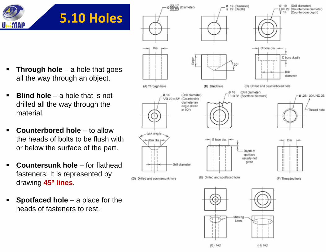
5.10 Holes
Through hole – a hole that goes all the way through an object.
Blind hole a hole that is notBlind hole – a hole that is not drilled all the way through the material.
Counterbored hole – to allow the heads of bolts to be flush with or below the surface of the part.
Countersunk hole – for flathead fasteners. It is represented by drawing 45º lines.
Spotfaced hole – a place for the heads of fasteners to rest.
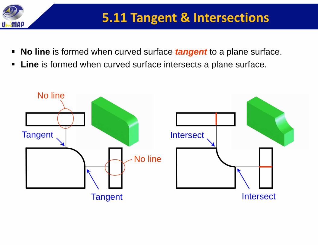
5.11 Tangent & Intersections
No line is formed when curved surface tangent to a plane surface.Line is formed when curved surface intersects a plane surface
N li
Line is formed when curved surface intersects a plane surface.
No line
Tangent Intersect
No line
Tangent Intersect
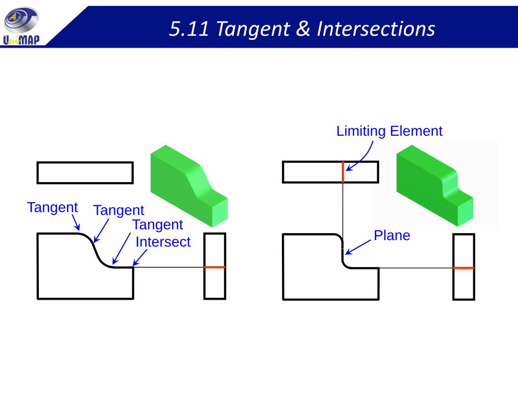
5.11 Tangent & Intersections
Limiting Element
Intersect
TangentTangent
Tangent
Plane
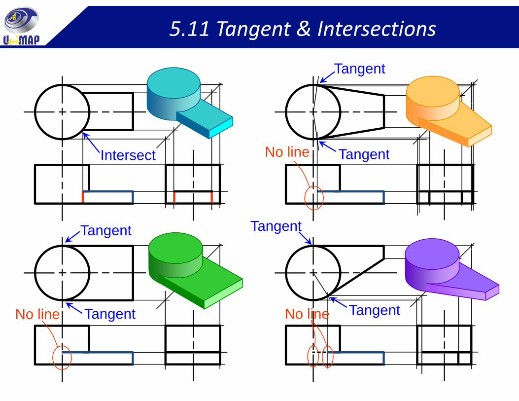
5.11 Tangent & Intersections
Tangent
I t t TangentNo lineIntersect TangentNo line
TangentTangent
No line Tangent TangentNo line
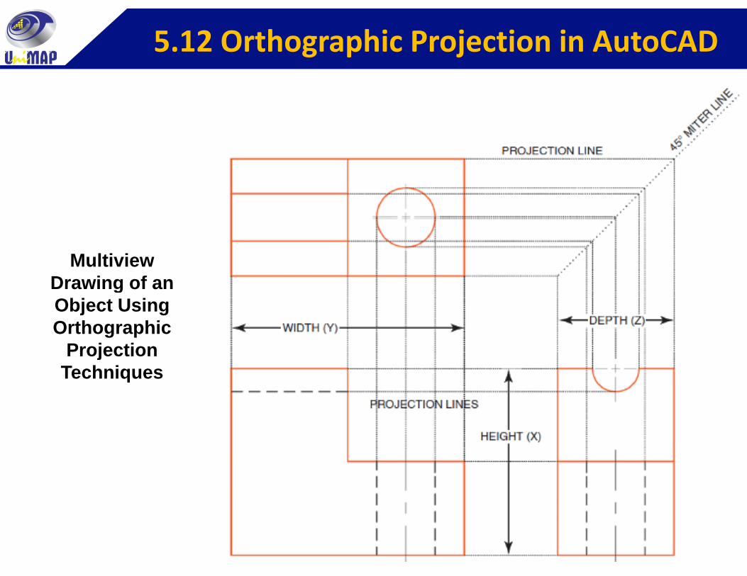
5.12 Orthographic Projection in AutoCAD
Multiview Drawing of anDrawing of an Object Using Orthographic
Projection jTechniques
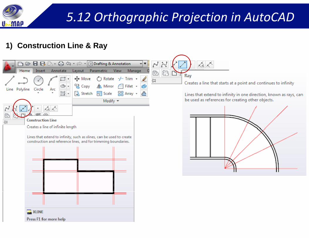
5.12 Orthographic Projection in AutoCAD
1) Construction Line & Ray
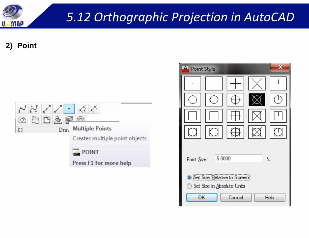
5.12 Orthographic Projection in AutoCAD
2) Point
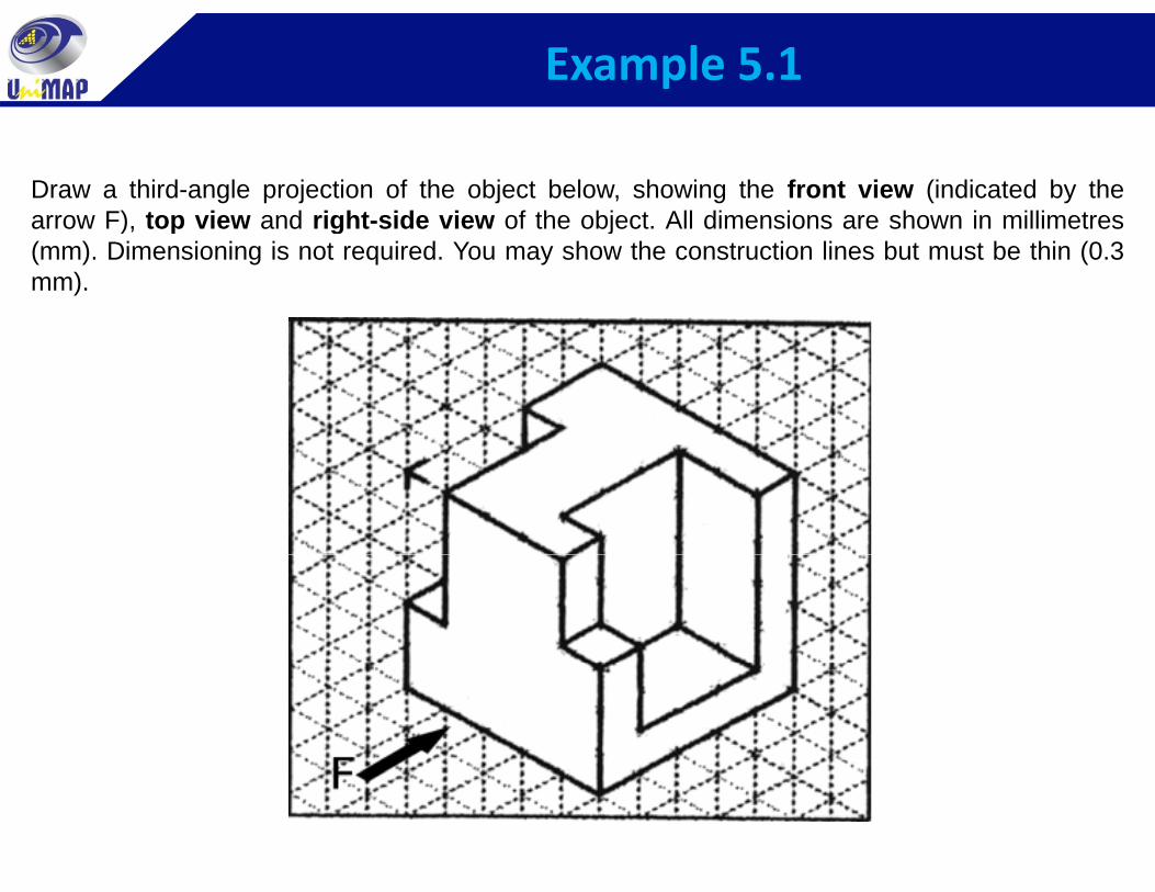
Example 5.1
Draw a third-angle projection of the object below, showing the front view (indicated by thearrow F), top view and right-side view of the object. All dimensions are shown in millimetres), p g j(mm). Dimensioning is not required. You may show the construction lines but must be thin (0.3mm).
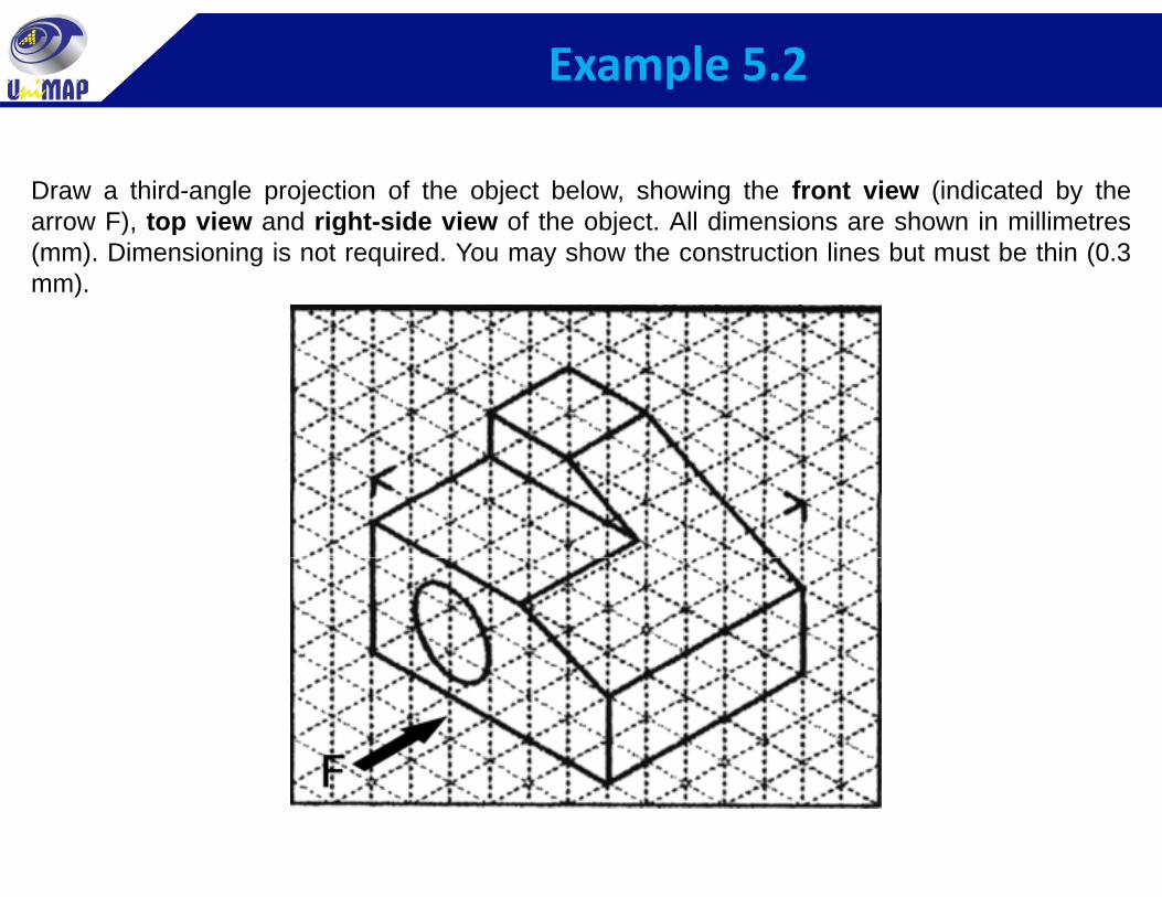
Example 5.2
Draw a third-angle projection of the object below, showing the front view (indicated by thearrow F), top view and right-side view of the object. All dimensions are shown in millimetres), p g j(mm). Dimensioning is not required. You may show the construction lines but must be thin (0.3mm).
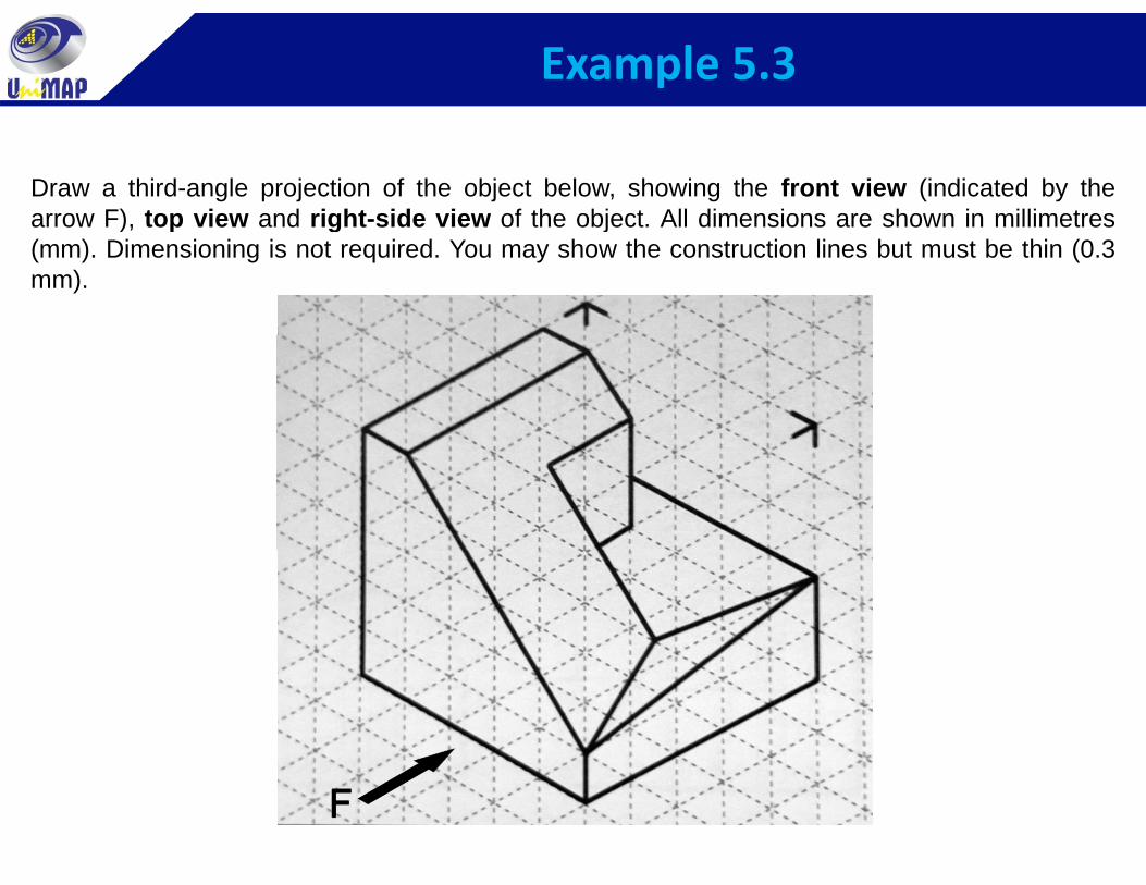
Example 5.3
Draw a third-angle projection of the object below, showing the front view (indicated by thearrow F), top view and right-side view of the object. All dimensions are shown in millimetres), p g j(mm). Dimensioning is not required. You may show the construction lines but must be thin (0.3mm).
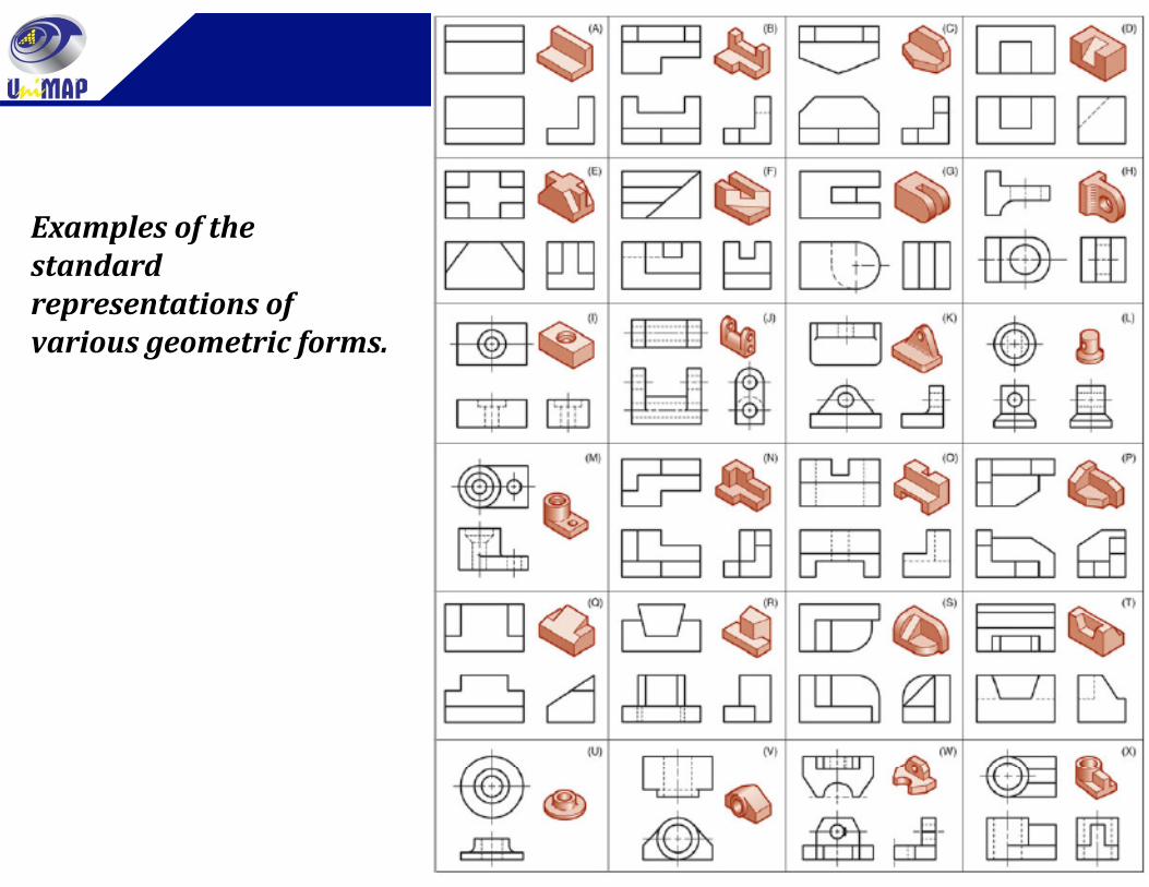
Examples of theExamples of the standard representations of
i t i fvarious geometric forms.
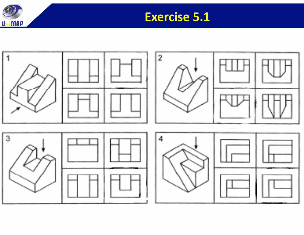
Exercise 5.1
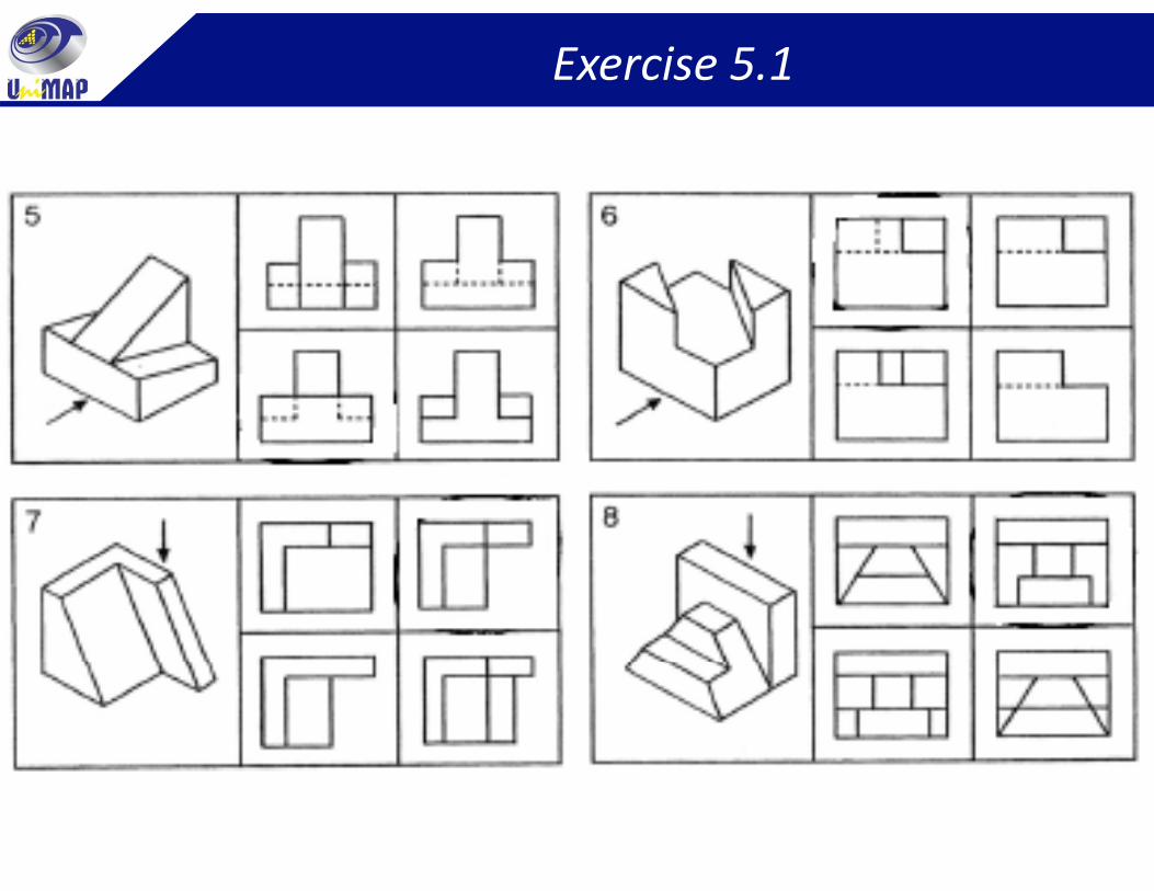
Exercise 5.1
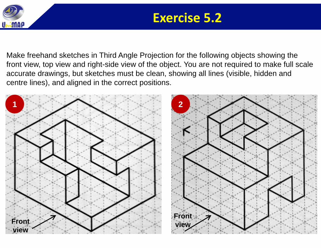
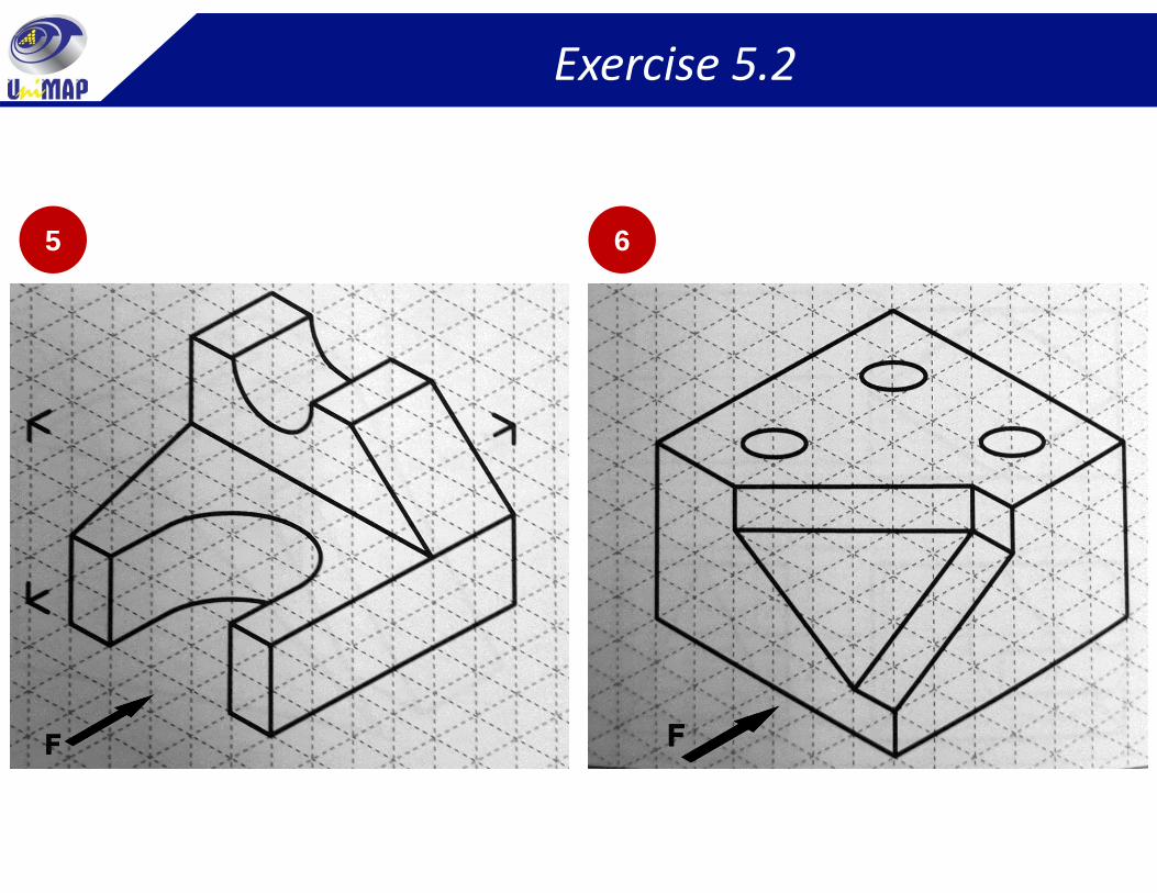
Exercise 5.2
Make freehand sketches in Third Angle Projection for the following objects showing the front view top view and right side view of the object You are not required to make full scalefront view, top view and right-side view of the object. You are not required to make full scale accurate drawings, but sketches must be clean, showing all lines (visible, hidden and centre lines), and aligned in the correct positions.
1 2
F tFrontview
Frontview
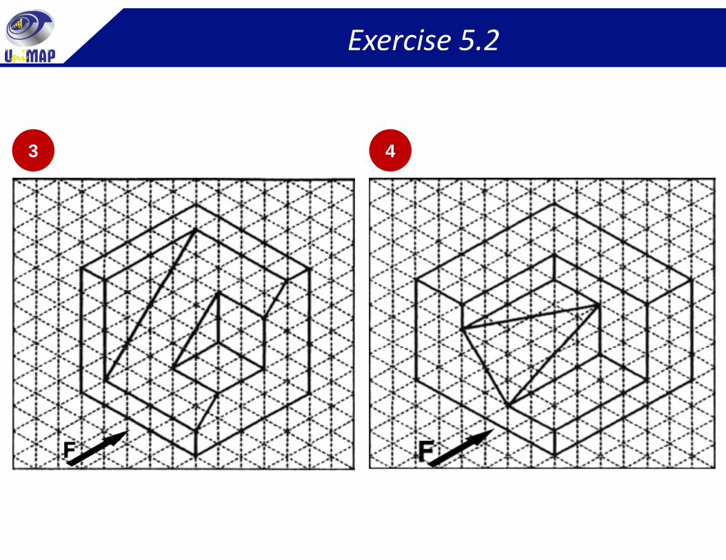
Exercise 5.2
3 43 4
Exercise 5.2
65 6