
Chapter 3: Lighting System & Design CHAPTER 3 LIGHTING...
36
PLT 302 : ELECTRICAL INSTALLATION I Chapter 3: Lighting System & Design
Transcript of Chapter 3: Lighting System & Design CHAPTER 3 LIGHTING...

CHAPTER 3
LIGHTING SYSTEM AND DESIGN
PLT 302 : ELECTRICAL INSTALLATION I
Chapter 3: Lighting System & Design

Luminaries
An apparatus which controls the distribution oflight from the source (lamp) and includes all therequired fixing arrangements, connections andprotectionsLuminous Flux/ Light Output
The total quantity of light emitted per second by alight source.
Lamp Lumens (lm) = the quantity of light emitted by alight source
Unit: Lumens (lm)
Faculty of Engineering TechnologyUniversiti Malaysia Perlis
Sept 20142
3.1 Definitions, Quantities and Units
Faculty of Engineering TechnologyUniversiti Malaysia Perlis
Sept 20143
3.1 Definitions, Quantities and Units
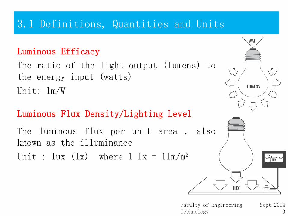
Luminous Efficacy
The ratio of the light output (lumens) tothe energy input (watts)
Unit: lm/W
Luminous Flux Density/Lighting Level
The luminous flux per unit area , alsoknown as the illuminance
Unit : lux (lx) where 1 lx = 1lm/m2

Faculty of Engineering TechnologyUniversiti Malaysia Perlis
Sept 20144
3.1 Definitions, Quantities and Units Luminous Intensity, I
A measure of light power of a source in a givendirection
Unit : candela (cd)Luminance, L
A measure of the intensity of the light per unit areagiven off from surface in a given direction
Unit : cd/m2
Illuminance, E
The luminous flux density at the surface or workingplane
Unit : lux (lx)Luminous intensity of a luminaire or lamp in allspatial directions and is normally shown in the formof a polar curve

Faculty of Engineering TechnologyUniversiti Malaysia Perlis
Sept 20145
3.1 Definitions, Quantities and Units
Polar Curve
is a schematic figure of theluminous intensity (Candela)distribution of the luminaire.
the shape of the polar curvesindicates the way in which theluminaire controls of the lightdistribution from the lamp.
Faculty of Engineering TechnologyUniversiti Malaysia Perlis
Sept 20146
3.2 Generation of Light
3.2.1Light SourceGenerally, a electric light sources can be divided into three types such as:i. Incandescentii. Luminescenceiii.Electroluminescence

Faculty of Engineering TechnologyUniversiti Malaysia Perlis
Sept 20147
3.2 Generation of Light
3.2.1.1 Incandescent•Solids and liquids emit visibleradiation when they are heated totemperatures aboves 1000K.•The intensity increases and theappearance becomes whiter as thetemperature increases.•This phenomenon is known asincandescence or temperatureradiation.
Faculty of Engineering TechnologyUniversiti Malaysia Perlis
Sept 20148
3.2 Generation of Light
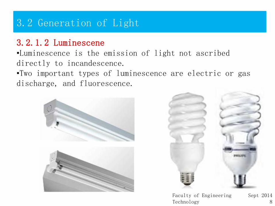
3.2.1.2 Luminescene•Luminescence is the emission of light not ascribed directly to incandescence.•Two important types of luminescence are electric or gas discharge, and fluorescence.

Faculty of Engineering TechnologyUniversiti Malaysia Perlis
Sept 20149
3.2 Generation of Light
3.2.1.3 Electroluminescence
•Electroluminescence is the emission of light when low voltage direct current is applied to a semi-conductor device containing a crystal and a p-n junction.•The most common electroluminescent device is the LED.

Faculty of Engineering TechnologyUniversiti Malaysia Perlis
Sept 201410
3.2 Generation of Light
3.2.2 Lamp Type Definition
An electric lamp is a device converting electric energy into light.
Lamp Types by Light Generation Methodi) Incandescent lampsii)Gas discharge lamps
High pressure or HID Mercury vapour (MV) Metal halide (MH) lamps High pressure sodium (HPS) lamps
iii) Electroluminescent lamps - LEDs

Faculty of Engineering TechnologyUniversiti Malaysia Perlis
Sept 201411
3.2 Generation of Light
3.2.2 Lamp Type
Types by Standard Classification Incandescent lamps Fluorescent lamp HID lamps
i. mercury vapour (MV) lampsii. metal halide (MH) lampsiii. high pressure sodium (HPS) lamps
Low pressure sodium (LPS) lamps LED sources

Faculty of Engineering TechnologyUniversiti Malaysia Perlis
Sept 201412
3.2 Generation of Light
3.2.3 Lighting Systemsa) Lighting Unit or Luminaire
A lighting unit consists of: a lamp or lamps a ballast (for gas discharge lamps) a fixture or housing an internal wiring and sockets a diffuser (louver or lens).
b) Lighting SystemA typical lighting system consists of: luminaires lighting control system(s).
c) Lighting System EnvironmentA lighting system environment consists of: room (ceiling, wall, floor) room objects.
Faculty of Engineering TechnologyUniversiti Malaysia Perlis
Sept 201413
3.2 Generation of Light
3.2.4 Incandescent Light
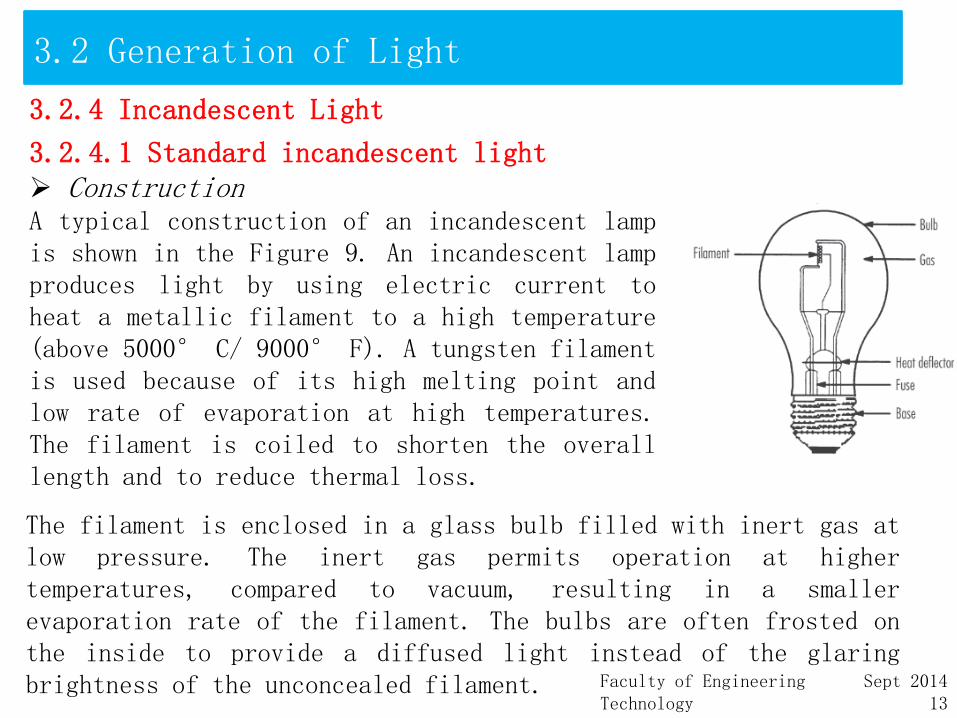
3.2.4.1 Standard incandescent light ConstructionA typical construction of an incandescent lampis shown in the Figure 9. An incandescent lampproduces light by using electric current toheat a metallic filament to a high temperature(above 5000° C/ 9000° F). A tungsten filamentis used because of its high melting point andlow rate of evaporation at high temperatures.The filament is coiled to shorten the overalllength and to reduce thermal loss.
The filament is enclosed in a glass bulb filled with inert gas atlow pressure. The inert gas permits operation at highertemperatures, compared to vacuum, resulting in a smallerevaporation rate of the filament. The bulbs are often frosted onthe inside to provide a diffused light instead of the glaringbrightness of the unconcealed filament.

Faculty of Engineering TechnologyUniversiti Malaysia Perlis
Sept 201414
3.2 Generation of Light
Shape
A = Arbitrary (standard) - universal use for home lightingB = Bullet - decorativeBR = Bulging reflector - for substitution of incandescent R lampsC = Cone shape - used mostly for small appliances and indicator lampsER = Elliptical reflector - for substitution of incandescent R lampsF = Flame - decorative interior lightingG = Globe - ornamental lighting and some floodlightsP = Pear - standard for streetcar and locomotive headlightsPAR = Parabolic aIuminized - used in spotlights and floodlights reflectorS = Straight - lower wattage lamps - sign and decorativeT = Tubular – showcase and appliance lighting

Faculty of Engineering TechnologyUniversiti Malaysia Perlis
Sept 201415
3.2 Generation of Light
3.2.4 Incandescent Light
3.2.4.2 Tungsten Halogen Lamp ConstructionThe quartz tungsten halogen lamp is another type of incandescentlamp.The conventional incandescent lamp loses filament material byevaporation which is deposited on the bulb wall, leading to bulbblackening and reduced lamp efficacy during the life of thelamp.When a halogen element is added to the filling gas under certaindesign conditions, a chemical reaction occurs, as a result ofwhich evaporated tungsten is redeposited on the filament,preventing any deposits on the bulb wall.The bulb of the tungsten halogen lamp is normally made of quartzglass to withstand the lamp’s high-temperature operatingconditions.The fixture often incorporates a reflector for better heatdissipation and beam control.

Faculty of Engineering TechnologyUniversiti Malaysia Perlis
Sept 201416
3.2 Generation of Light
Shape
Tubular:T3 : Line voltage tungsten halogen lamp - double-ended
Tubular:T10 : Line voltage tungsten halogen lamp - single-ended
Tubular:T6 : Line voltage tungsten halogen lamp - single-ended
Tubular:T-4 : Line voltage tungsten halogen lamp - without reflector
Tubular:T-3 : Low voltage tungsten halogen lamp - without reflector
Maxi-spot : Low voltage tungsten halogen lamp - with reflector
Mini-spot : Low voltage tungsten halogen lamp - with reflector
PAR 36 : Low voltage tungsten halogen lamp - PAR36 reflector
MR 16 : Low voltage tungsten halogen lamp – MR16 Reflector

Faculty of Engineering TechnologyUniversiti Malaysia Perlis
Sept 201417
3.2 Generation of Light
3.2.4 Incandescent Light
3.2.4.3 Halogen PAR LampGeneral DescriptionHalogen PAR lamps are lamps with a Parabolic Aluminum Reflector(PAR) which use a halogen capsule instead of a simple filament.The halogen capsule includes a tungsten filament and halogen gas.
PAR Lamp FamiliesPAR lamps have evolved into four families, listed below, fromlowest to highest efficiency:
i. standard PAR lampsii. energy saving PAR lampsiii.halogen PAR lampsiv. Infra Red (IR) halogen PAR lamps.

Faculty of Engineering TechnologyUniversiti Malaysia Perlis
Sept 201418
3.2 Generation of Light
• All PAR lamps have an aluminum or silver coating reflector on part of the bulb’s
surface.PAR lamps are used for directional lighting, i.e., highlighting or spot
lighting.
• Most common size is the PAR38 and other sizes include PAR30, PAR20 and
PAR16.
• Beam spreads are described as narrow spot (NS), spot (SP) and flood (FL).
Halogen PAR Lamps
• Halogen PAR lamps use a halogen capsule instead of a tungsten filament.
• Lamp watts: 45 W, 65 W, 90 W.
• Life: 2,000 hours.
Applications
• Downlights,
• Accent lighting,
• Outdoor lighting.
Faculty of Engineering TechnologyUniversiti Malaysia Perlis
Sept 201419
3.2 Generation of Light
Advantages
Halogen PAR lamps have many advantages over standard and energy saving
PAR lamps:
• energy savings in the order of 40% - 60%;
• whiter light;
• constant light output throughout lamp life without lamp darkening.
Limitations
Halogen PAR lamps are more expensive than standard and energy saving PAR.
Assessment
• Halogen PAR lamps provide energy savings which outweigh the lamp price
difference in less than a year.
• Halogen PAR lamps provide better quality light.

Faculty of Engineering TechnologyUniversiti Malaysia Perlis
Sept 201420
3.2 Generation of Light
3.2.4.4 Gas Discharge Lampi. Low Pressure Discharge
1) Fluorescent Lamp (Low pressure mercury vapour lamp)ConstructionA fluorescent lamp is a low-pressure mercury electric dischargelamp.A fluorescent lamp consists of a glass tube filled with amixture of argon gas and mercury vapour at low pressure.When current flows through the ionized gas between theelectrodes, it emitsultraviolet (UV) radiation fromthe mercury arc.The UV radiation is converted tovisible light by a fluorescentcoating on the inside of the tube.The lamp is connected to the powersource through a ballast, whichprovides the necessary startingvoltage and operating current.

Faculty of Engineering TechnologyUniversiti Malaysia Perlis
Sept 201421
3.3 Calculation of Lighting Requirement
3.3.1 Inverse SquareIf we were to illuminate a surface by means of a lamppositioned vertically above it, measure theillumination at the surface, and then move the lamptwice as far away, the illumination now measuredwould be four times less.
Faculty of Engineering TechnologyUniversiti Malaysia Perlis
Sept 201422
3.3 Calculation of Lighting Requirement
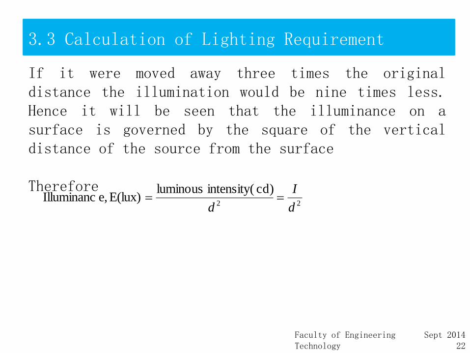
If it were moved away three times the originaldistance the illumination would be nine times less.Hence it will be seen that the illuminance on asurface is governed by the square of the verticaldistance of the source from the surface
Therefore22
cd)intensity( luminousE(lux)e,Illuminanc
d
I
d

Faculty of Engineering TechnologyUniversiti Malaysia Perlis
Sept 201423
3.3 Calculation of Lighting Requirement
3.3.2 Cosine RuleFrom figure below it will be seen that point X isfurther from the source than is point Y. Theilluminance at this point is therefore less. In factthe illuminance at X depends on the cosine of theangle θ. Hence,
2
3cos
d
lEx
Faculty of Engineering TechnologyUniversiti Malaysia Perlis
Sept 201424
3.3 Calculation of Lighting Requirement
Example 1A light source of 900 candelas is situated 3m above a working surface.Calculate the illuminance directly below the source.What would be the illuminace if the lamp were moved to a position 4m from the surface?

Faculty of Engineering TechnologyUniversiti Malaysia Perlis
Sept 201425
3.3 Calculation of Lighting Requirement
Example 2A 250W sodium vapour street lamp emits a light of 22500 cd and is situated 5m above the road. Calculate the illuminancea) direct below the lamp andb) at a horizontal distance along the road of 6m.
Faculty of Engineering TechnologyUniversiti Malaysia Perlis
Sept 201426
3.4 Lighting Design
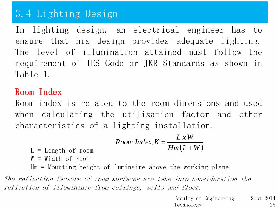
In lighting design, an electrical engineer has toensure that his design provides adequate lighting.The level of illumination attained must follow therequirement of IES Code or JKR Standards as shown inTable 1.
Room IndexRoom index is related to the room dimensions and usedwhen calculating the utilisation factor and othercharacteristics of a lighting installation.
W L Hm
W x L K Index, Room
L = Length of roomW = Width of roomHm = Mounting height of luminaire above the working plane
The reflection factors of room surfaces are take into consideration the reflection of illuminance from ceilings, walls and floor.
Faculty of Engineering TechnologyUniversiti Malaysia Perlis
Sept 201427
3.4 Lighting Design
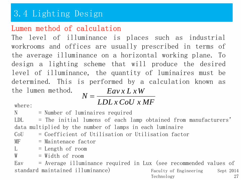
Lumen method of calculationThe level of illuminance is places such as industrialworkrooms and offices are usually prescribed in terms ofthe average illuminance on a horizontal working plane. Todesign a lighting scheme that will produce the desiredlevel of illuminance, the quantity of luminaires must bedetermined. This is performed by a calculation known asthe lumen method.
where:N = Number of luminaires requiredLDL = The initial lumens of each lamp obtained from manufacturers’data multiplied by the number of lamps in each luminaireCoU = Coefficient of Utilisation or Utilisation factorMF = Maintenace factorL = Length of roomW = Width of roomEav = Average illuminance required in Lux (see recommended values ofstandard maintained illuminance)
MF x CoU x LDL
W x L x EavN

Faculty of Engineering TechnologyUniversiti Malaysia Perlis
Sept 201428
3.4 Lighting Design
In order to find the coefficient of utilisation, CoU,the room index,K must be calculated first. Havingdone this assessment is made of the room reflectance.Both room index and reflector factors are thenapplied to the manufacturers’ photometric data todetermine the utilisation factor for the luminaire.
Faculty of Engineering TechnologyUniversiti Malaysia Perlis
Sept 201429
3.4 Uniformity of Illuminance
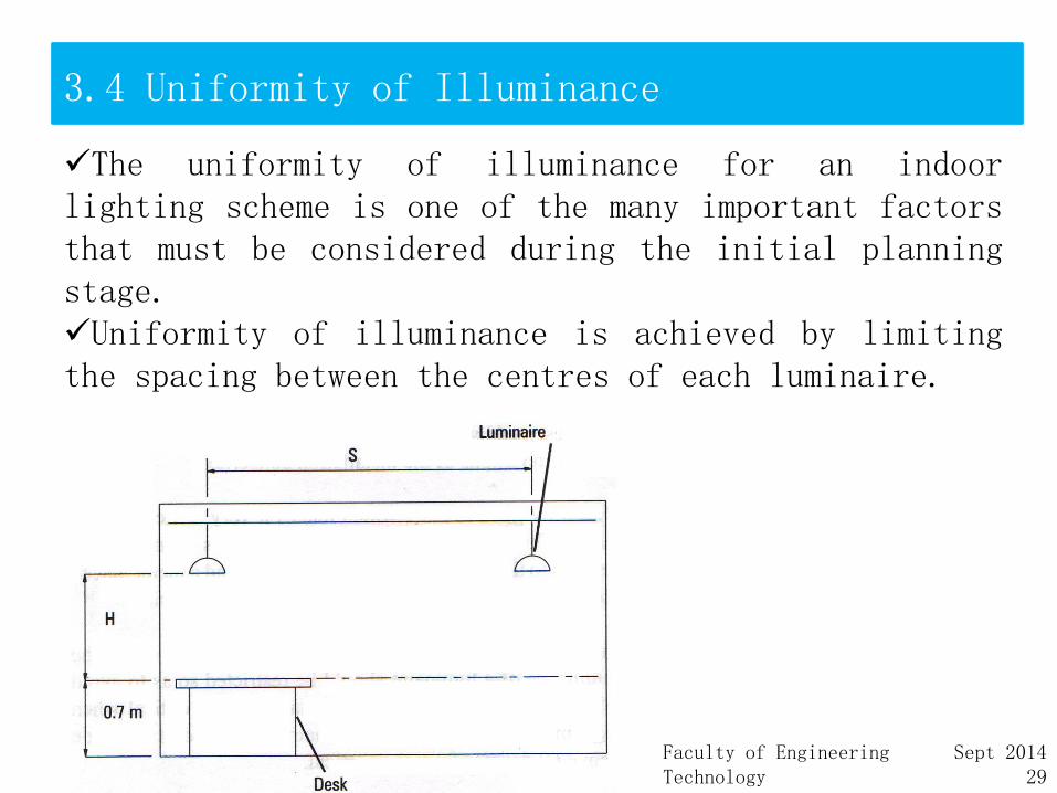
The uniformity of illuminance for an indoorlighting scheme is one of the many important factorsthat must be considered during the initial planningstage.Uniformity of illuminance is achieved by limitingthe spacing between the centres of each luminaire.
Faculty of Engineering TechnologyUniversiti Malaysia Perlis
Sept 201430
3.4 Uniformity of Illuminance
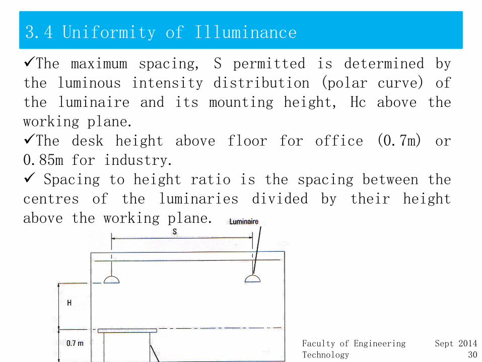
The maximum spacing, S permitted is determined bythe luminous intensity distribution (polar curve) ofthe luminaire and its mounting height, Hc above theworking plane.The desk height above floor for office (0.7m) or0.85m for industry. Spacing to height ratio is the spacing between thecentres of the luminaries divided by their heightabove the working plane.
Faculty of Engineering TechnologyUniversiti Malaysia Perlis
Sept 201431
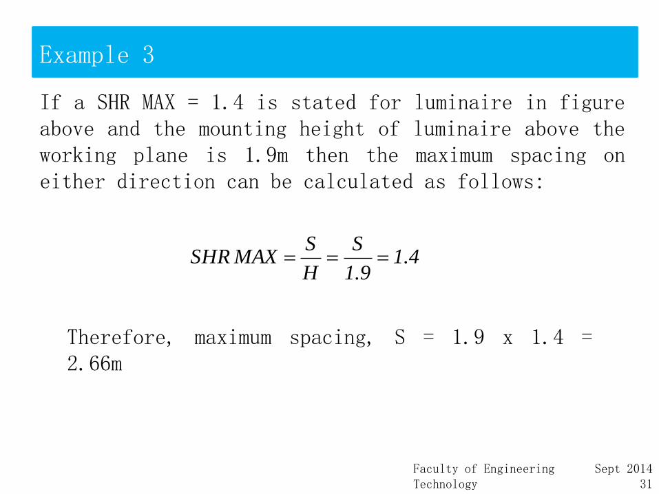
Example 3
If a SHR MAX = 1.4 is stated for luminaire in figureabove and the mounting height of luminaire above theworking plane is 1.9m then the maximum spacing oneither direction can be calculated as follows:
4.19.1
S
H
S MAXSHR
Therefore, maximum spacing, S = 1.9 x 1.4 =2.66m

Faculty of Engineering TechnologyUniversiti Malaysia Perlis
Sept 201432
Example 3

Faculty of Engineering TechnologyUniversiti Malaysia Perlis
Sept 201433
3.4 Uniformity of Illuminance
If the spacing height ratio is exceeded then therewill be areas between luminaries which will haveserious reduction of illuminance as shown in figurebelow
It is recommended that the ratio of the minimumilluminance to the average illumainance over theworking plane should not less than 80%.
Faculty of Engineering TechnologyUniversiti Malaysia Perlis
Sept 201434
3.4 Uniformity of Illuminance
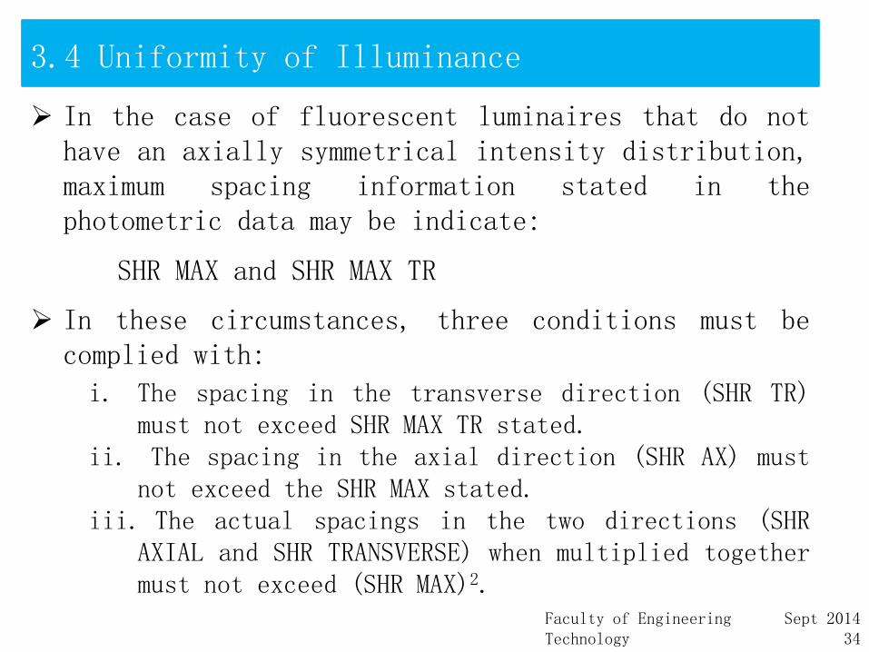
In the case of fluorescent luminaires that do nothave an axially symmetrical intensity distribution,maximum spacing information stated in thephotometric data may be indicate:
SHR MAX and SHR MAX TR
In these circumstances, three conditions must becomplied with:
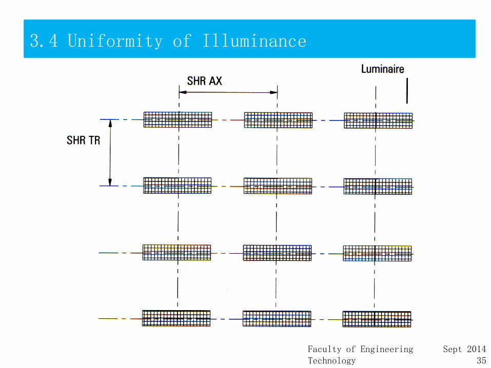
i. The spacing in the transverse direction (SHR TR)must not exceed SHR MAX TR stated.
ii. The spacing in the axial direction (SHR AX) mustnot exceed the SHR MAX stated.
iii. The actual spacings in the two directions (SHRAXIAL and SHR TRANSVERSE) when multiplied togethermust not exceed (SHR MAX)2.
Faculty of Engineering TechnologyUniversiti Malaysia Perlis
Sept 201435
3.4 Uniformity of Illuminance

Faculty of Engineering TechnologyUniversiti Malaysia Perlis
Sept 201436
3.4 Example 4
An office area requires an average illuminance of 500 luxon the working plane, 0.75m from the floor. Officedimensions are 10m long by 6m wide. Ceiling height is2.68m and painted white. Walls have also a light finishedsurface.Room surface reflection factors are:
Ceiling, C = 0.70Walls, W = 0.50Floor, F = 0.20
Assume a maintenance factor to be 0.85.Determines the total number of luminaires for the officestogether with a plan view of their spacing arrangement forthese types of lamp is used in this lighting design:i. TL-5 (3x36W)ii. LED downlightiii.CFL downlight


![DNT 126 Basic Computer Programming [Asas Pengaturcaraan ...portal.unimap.edu.my/portal/page/portal30/Lecture...hadapan sebelum anda memulakan peperiksaan ini.] This question paper](https://static.fdocuments.in/doc/165x107/611b16d1db385263f31b1167/dnt-126-basic-computer-programming-asas-pengaturcaraan-hadapan-sebelum.jpg)


![index [portal.unimap.edu.my]portal.unimap.edu.my/portal/page/portal30/Lecture Notes...Programmable Logic Devices (PLDs) are ICs with a large number of gates and flip flops that can](https://static.fdocuments.in/doc/165x107/5e7054cbeb00c9419349ced3/index-notes-programmable-logic-devices-plds-are-ics-with-a-large-number.jpg)