
CHAPTER 3 FORMS OF CORROSION (cont’) Chapter Outlines 3.5 Selective Leaching 3.6 Erosion Corrosion...
80
CHAPTER 3 CHAPTER 3 FORMS OF CORROSION FORMS OF CORROSION (cont’) (cont’) Chapter Outlines 3.5 Selective Leaching 3.6 Erosion Corrosion 3.7 Stress Corrosion
-
Upload
marvin-lester -
Category
Documents
-
view
238 -
download
8
Transcript of CHAPTER 3 FORMS OF CORROSION (cont’) Chapter Outlines 3.5 Selective Leaching 3.6 Erosion Corrosion...
CHAPTER 3CHAPTER 3
FORMS OF CORROSIONFORMS OF CORROSION(cont’)(cont’)
Chapter Outlines
3.5 Selective Leaching3.6 Erosion Corrosion3.7 Stress Corrosion3.8 Hydrogen Damage

SELECTIVE LEACHINGSELECTIVE LEACHING

SELECTIVE LEACHING (“Dealloying”, “Parting”)
Corrosion in which one constituent of an alloy is preferentially removed, leaving behind an altered (weakened) residual structure.
Can occur in several systems.

Combinations of alloys and environments subject to dealloying and elements preferentially removed
Alloy Environment Element removed
BrassesMany waters, especially under stagnant conditions
Zn (dezincification)
Grey ironAluminium bronzes
Soils, many watersHCl, acids containing Chloride
Fe (graphitic corrosion)Al (dealuminification)
Silicon bronzes High-temperature steam and acidic species Si (desiliconification)
Tin bronzesCopper-nickels
Hot brine or steamHigh heat flux and low water velocity (in refinery condenser tubes)
Sn (destannification)Ni (denickelification)
Copper-gold single crystalsMonels
Ferric chlorideHydrofluoric and other acids
CuCu in some acids, and Ni in others
Gold alloys with copper or silverHigh-nickel alloys
Sulfide solutions, human salivaMolten salts
Cu, Ag, Cr, Fe, Mo and T
Medium- and high-carbon steels
Oxidizing atmospheres, hydrogen at high temperatures
C (decarburization)
Iron-chromium alloys High-temperature oxidizing atmospheres Cr, which forms a protective film
Nickel-molybdenum alloys Oxygen at high temperature Mo

Dezincification
All Cu-Zn alloys (Brasses) containing > 15% Zn are susceptible . . .
e.g. common yellow brass . . . 30 Zn 70 Cu, dezincifies to red copper-rich structure. Dezincification can be uniform...
- potable water inside
- or plug-type.... (boiler water inside, combustion gases outside)
Uniform dezincification of brass pipe.
Plug-type dezincification.

Overall dimensions of original material tend to be retained . . . residual is spongy and porous . . . often brittle.
Can go unnoticed, especially if covered with dirt/deposit, etc.
Uniform dezincification...
- usually found in high brasses (high[Zn]), acid environments;
Plug-type dezincification...
- usually found in low brasses, alkaline, neutral or slightly acid environments.
Section of one of the plugs shown before

Prevention
- Make environment less aggressive (e.g., reduce O2 content);
- Cathodically protect;
- Use a better alloy (common cure - above not usually feasible)... - “red” brass (<15% Zn) almost immune - Admiralty Brass. . . 70 Cu, 29 Zn, 1 Sn; - arsenical Admiralty. . . 70 Cu, 29 Zn, 1 Sn, 0.04 As (Sn and Sn-As in deposited films hinder redeposition of Cu);
- For very corrosive environments likely to provoke dezincification, or for critical components, use . . . - cupronickels 70-90 Cu, 30-10 Ni.
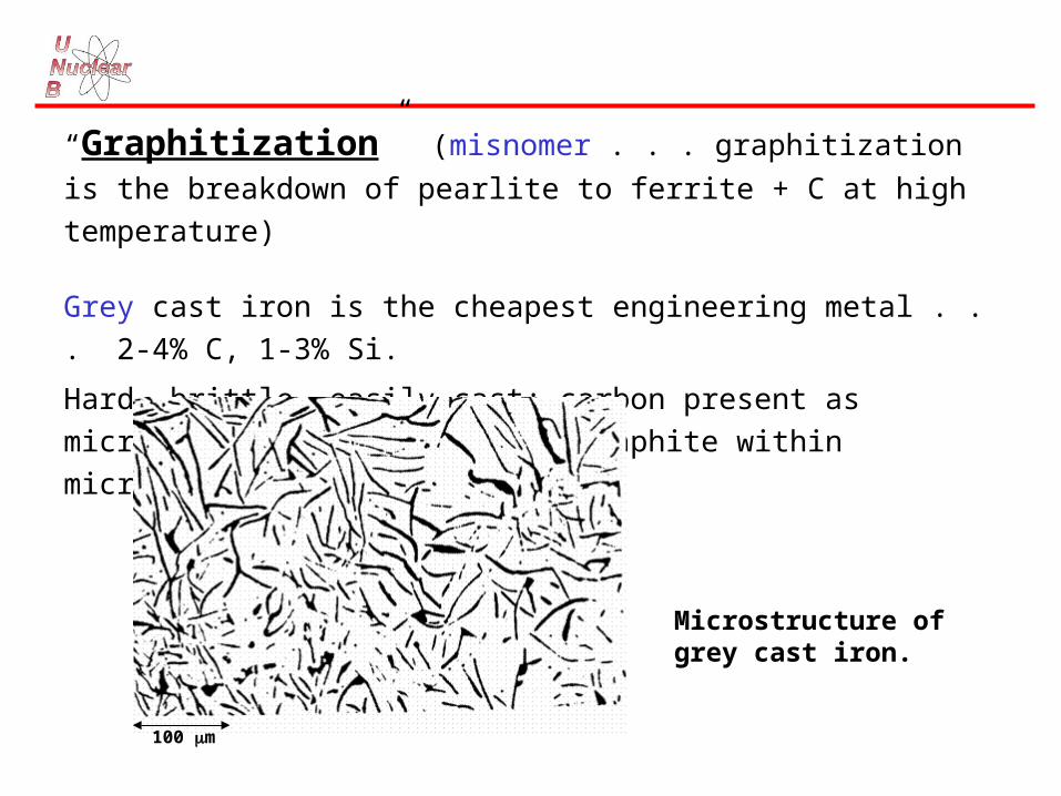
“Graphitization” (misnomer . . . graphitization is the breakdown of
pearlite to ferrite + C at high temperature)
Grey cast iron is the cheapest engineering metal . . . 2-4% C, 1-3% Si.
Hard, brittle, easily cast; carbon present as microscopic flakes of matrix
graphite within microstructure.
Microstructure of grey cast iron.
100 m
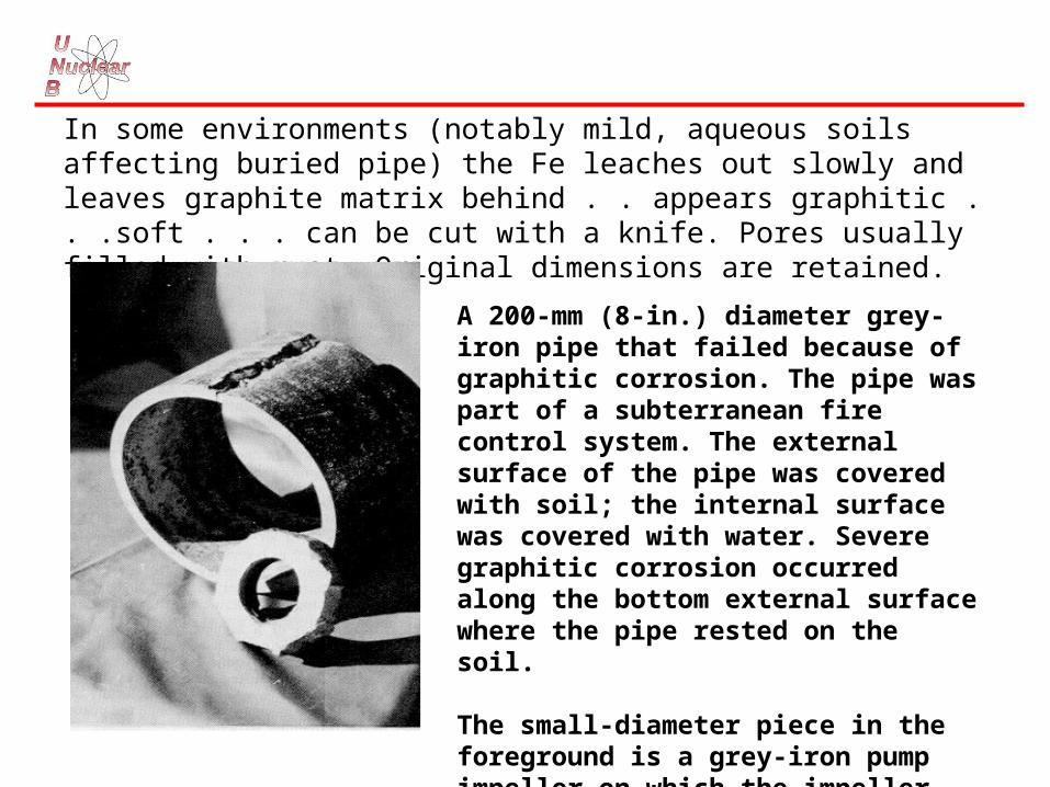
In some environments (notably mild, aqueous soils affecting buried pipe) the Fe leaches out slowly and leaves graphite matrix behind . . appears graphitic . . .soft . . . can be cut with a knife. Pores usually filled with rust. Original dimensions are retained.
A 200-mm (8-in.) diameter grey-iron pipe that failed because of graphitic corrosion. The pipe was part of a subterranean fire control system. The external surface of the pipe was covered with soil; the internal surface was covered with water. Severe graphitic corrosion occurred along the bottom external surface where the pipe rested on the soil.
The small-diameter piece in the foreground is a grey-iron pump impeller on which the impeller vanes have disintegrated because of graphitic corrosion.
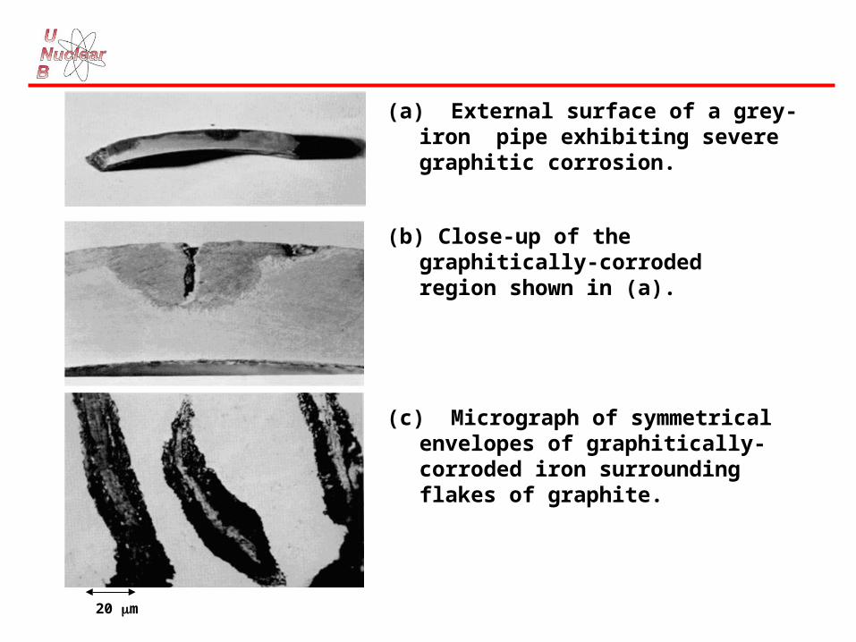
(a) External surface of a grey-iron pipe exhibiting severe graphitic corrosion.
(b) Close-up of the graphitically-corroded region shown in (a).
(c) Micrograph of symmetrical envelopes of graphitically-corroded iron surrounding flakes of graphite.
20 m
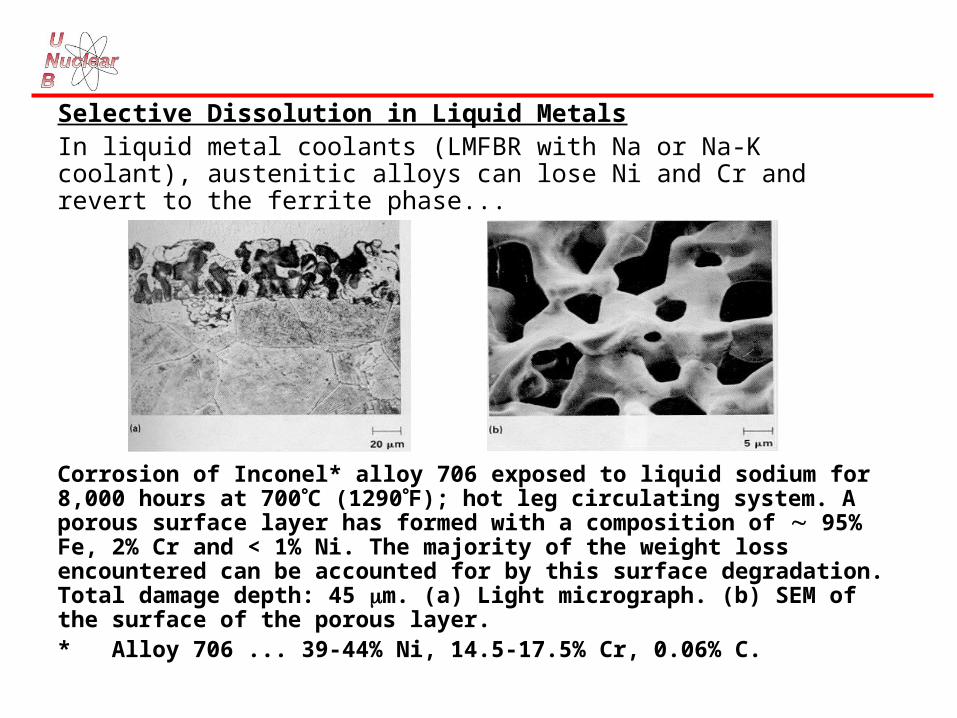
Selective Dissolution in Liquid MetalsIn liquid metal coolants (LMFBR with Na or Na-K coolant), austenitic alloys can lose Ni and Cr and revert to the ferrite phase...
Corrosion of Inconel* alloy 706 exposed to liquid sodium for 8,000 hours at 700C (1290F); hot leg circulating system. A porous surface layer has formed with a composition of 95% Fe, 2% Cr and < 1% Ni. The majority of the weight loss encountered can be accounted for by this surface degradation. Total damage depth: 45 m. (a) Light micrograph. (b) SEM of the surface of the porous layer.* Alloy 706 ... 39-44% Ni, 14.5-17.5% Cr, 0.06% C.

Also in fusion-reactor environments (Li as coolant)....
Light micrograph of cross-section. SEM of surface showing porous layer.
Corrosion of type 316 stainless steel exposed to thermally convective lithium for 7488 hours at the maximum loop temperature of 600C.

Usually, the transport and deposition of leached elements is of more concern than the actual corrosion.
(a) (b)
SEM micrographs of chromium mass transfer deposits found at the 460C (860C) position in the cold leg of a lithium/type-316-stainless-steel thermal convection loop after 1700 hours. Mass transfer deposits are often a more serious result of corrosion than wall thinning. (a) Cross section of specimen on which chromium was deposited. (b) Top view of surface.

Iron crystals found in a plugged region of a failed pump channel of a lithium processing test loop.
100 m
Selective Leaching in Molten Salts
Molten salts are ionic conductors (like aqueous solutions) and can promote anodic-cathodic electrolytic cells . . . they can be aggressive to metals.
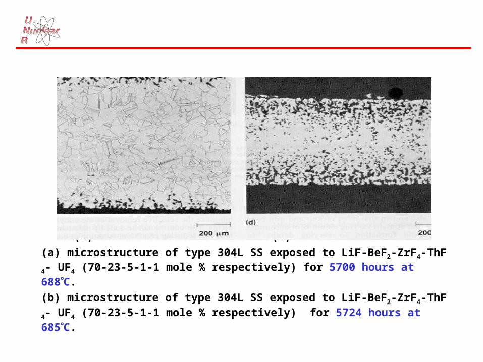
ALSO . . . some molten salts (notably fluorides) are “Fluxes” and dissolve surface deposits that would otherwise be protective: dealloying of Cr from Ni-base alloys and stainless steels can occur in the surface layers exposed to molten fluorides; the vacancies in the metal lattice then coalesce to form subsurface voids which agglomerate and grow with increasing time and temperature.
(a) (b)
(a) microstructure of type 304L SS exposed to LiF-BeF2-ZrF4-ThF4- UF4 (70-23-5-1-1 mole % respectively) for 5700 hours at 688C.
(b) microstructure of type 304L SS exposed to LiF-BeF2-ZrF4-ThF4- UF4 (70-23-5-1-1 mole % respectively) for 5724 hours at 685C.
EROSION CORROSIONEROSION CORROSION

EROSION-CORROSION (“Flow-Assisted” or “Flow-Accelerated” Corrosion)
An increase in corrosion brought about by a high relative velocity between the corrosive environment and the surface.
Removal of the metal may be:• as corrosion product which “spalls off” the surface because of the high fluid
shear and bares the metal beneath;• as metal ions, which are swept away by the fluid flow before they can
deposit as corrosion product.
Remember the distinction between erosion-corrosion and erosion:• erosion is the straightforward wearing away by the mechanical abrasion
caused by suspended particles . . . e.g., sand-blasting, erosion of turbine blades by droplets . . .
• erosion-corrosion also involves a corrosive environment . . . the metal undergoes a chemical reaction.
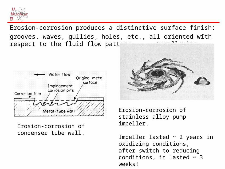
Erosion-corrosion produces a distinctive surface finish:
grooves, waves, gullies, holes, etc., all oriented with respect to the fluid flow pattern . . . “scalloping”...
Erosion-corrosion of condenser tube wall.
Erosion-corrosion of stainless alloy pump impeller.
Impeller lasted ~ 2 years in oxidizing conditions;after switch to reducing conditions, it lasted ~ 3 weeks!
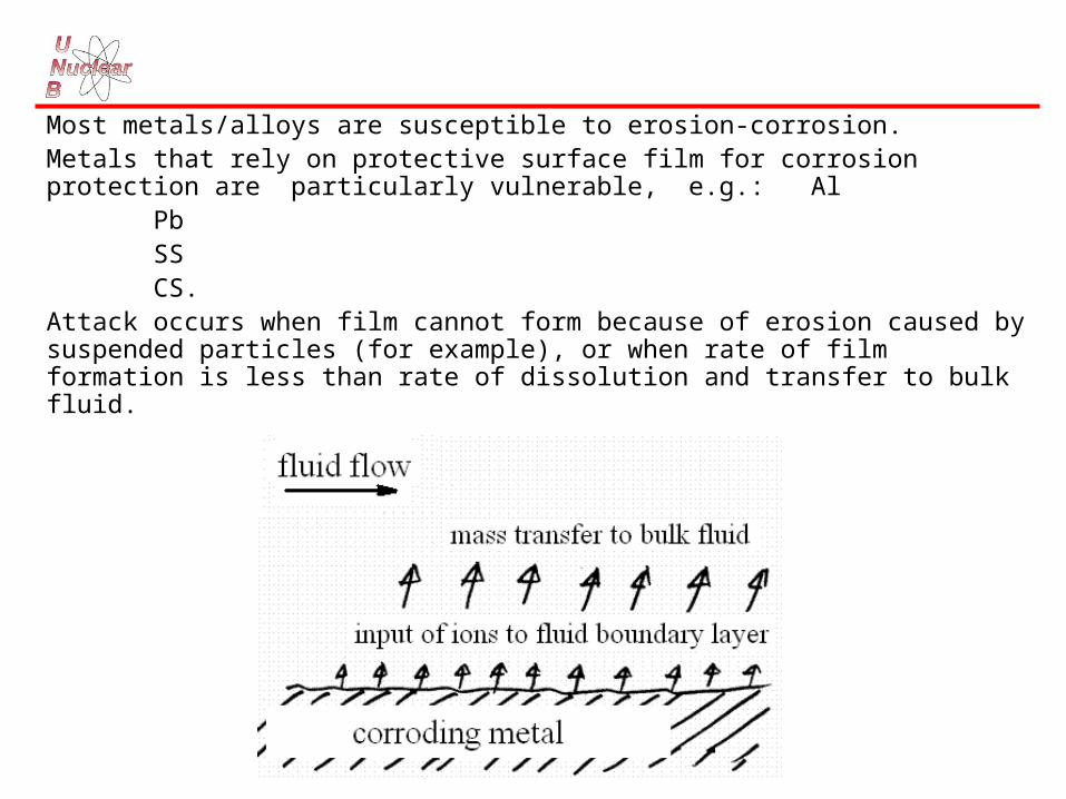
Most metals/alloys are susceptible to erosion-corrosion.Metals that rely on protective surface film for corrosion protection are particularly vulnerable, e.g.: Al
Pb SS CS.
Attack occurs when film cannot form because of erosion caused by suspended particles (for example), or when rate of film formation is less than rate of dissolution and transfer to bulk fluid.

Erosion-Corrosion found in: - aqueous solutions;- gases;- organic liquids;- liquid metal.
If fluid contains suspended solids, erosion-corrosion may be aggravated. Vulnerable equipment is that subjected to high-velocity fluid, to rapid change in
direction of fluid, to excessive turbulence . . .viz. equipment in which the contacting fluid has a very thin boundary layer
- high mass transfer rates.Vulnerable equipment includes:
- pipes (bends, elbows, tees);- valves;- pumps;- blowers;- propellers, impellers;- stirrers;- stirred vessels;- HX tubing (heaters, condensers);
- flow-measuring orifices, venturies;- turbine blades;- nozzles;- baffles;- metal-working equipment (scrapers, cutters, grinders, mills);- spray impingement components;- etc.

Surface film effects
Protective corrosion-product films important for resistance to erosion-corrosion.
Hard, dense, adherent, continuous films give good resistance, provided that they are not brittle and easily removed under stress.
Lead sulphate film protects lead against DILUTE H2SO4 under stagnant conditions, but not under rapidly moving conditions.
Erosion-corrosion of hard lead by 10% sulphuric acid (velocity 39 ft/sec).

pH affects films in erosion-corrosion of low-alloy steel.
Scale generally granular Fe3O4 (non-protective). But at pH 6 & pH 10, scale Fe(OH)2/Fe(OH)3 . . . hinders mass transport of oxygen and ionic species.
Effect of pH of distilled water on erosion-corrosion of carbon steel at 50C (velocity 39 ft/sec).

Dissolved O2 often increases erosion-corrosion . . .
e.g. copper alloys in seawater. . . BUT . . . on steels, dissolved O2 will inhibit erosion-corrosion . . . utilized in boiler feedwater systems.
Effects of temperature and dissolved O2 on the weight-loss of AISI 304 stainless steel exposed for 800 hours in flowing water at 3.7 m/s.

Effect of oxygen dosing on erosion-corrosion and potential of carbon steel in water at 150C, pH at 25oC= 7.8.

Good resistance of Ti to erosion-corrosion in:
- seawater;
- Cl- solutions;
- HNO3;
and many other environments.
Resistance depends on formation and stability of TiO2 films.

Chromium imparts resistance to erosion-corrosion to: - steels;
- Cu alloys.
Such tests have led to the marketing of a new alloy for condenser tubes . . “CA-722” . . . previously “IN-838” . . . with constituents . . . Cu-16Ni-0.4Cr.
Effect of chromium additions on seawater impingement-corrosion resistance of copper-nickel alloys. 36-day test with 7.5 m/s jet velocity; seawater temperature: 27C.

Velocity Effects
N.B. Turbulent flow regime for V < Vc is sometimes called
Flow-Assisted Corrosion regime.
Schematic showing the effect of flow velocity on erosion-corrosion rate.

Relationship between flow velocity, v, and erosion-corrosion rate, w, may be written as . . .
w = kva where k and a are constants that depend on the system.
DISCUSS: What happens when v = 0 ?How do we express no dependence on velocity?
The exponent a varies between . . .0.3 (laminar flow) and 0.5 (turbulent flow)...occasionally reaching > 1.0 for mass transfer and fluid shear
effects.
For mechanical removal of oxide films (spalling), the fluid shear stress at the surface is important, and a > 1.0 . . . (may reach 2 - 4).

Erosion-Corrosion in Carbon Steel and Low-Alloy Steels
N.B. these materials are used extensively in boilers, turbines, feed-water heaters in fossil & nuclear plants.
High velocities occur in single-phase flow (water) and two-phase flow (wet steam).
Single-phase E-C seen in H.P. feedwater heaters, SG inlets in AGRs, feedwater pumps.
Two-phase E-C more widespread . . . steam extraction piping, cross-over piping (HP turbine to moisture separator), steam side of feedwater heaters.

Material effects – low-alloy steel . . .
Erosion-corrosion loss as a function of time for mild steel and 1 Cr 0.5 Mo steel in water (pH at 25C = 9.05) flowing through an orifice at 130C.
Cr additions reduce E-C.
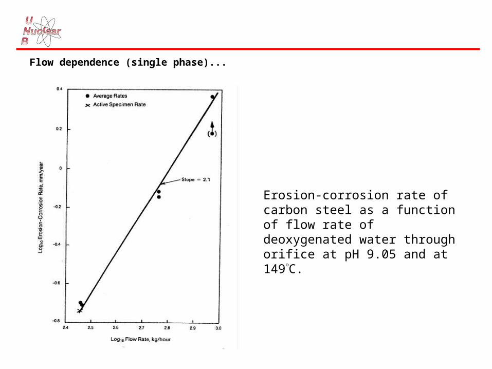
Flow dependence (single phase)...
Erosion-corrosion rate of carbon steel as a function of flow rate of deoxygenated water through orifice at pH 9.05 and at 149C.

Mechanism... for E-C of C.S. in high temperature de-oxygenated water...
- magnetite film dissolves reductively
Fe3O4 + (3n-4) H2O + 2e
3Fe(OH)n(2-n) + (3n-8)H+
- high mass transfer rates remove soluble Fe II species;
- oxide particles eroded from weakened film by fluid shear stress;
- metal dissolves to try and maintain film.
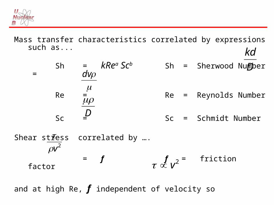
Mass transfer characteristics correlated by expressions such as...
Sh = kRea Scb Sh = Sherwood Number =
Re = Re = Reynolds Number
Sc = Sc = Schmidt Number
Shear stress correlated by ….
= f f = friction factor
and at high Re, f independent of velocity so
D
kd
dv
D
2v
2v

Temperature and pH dependence for single-phase E-C of CS . . .
Effect of temperature on the exponent of the mass transfer coefficient for the erosion-corrosion of carbon steel in flowing water at various pHs.
Prevention of Erosion-Corrosion
• design (avoid impingement geometries, high velocity, etc.);
• chemistry (e.g., in steam supply systems . . . for CS or low-alloy steel add O2, maintain pH > 9.2, use morpholine rather than NH3);
• materials (use Cr-containing steels);
• use hard, corrosion-resistant coatings.

CAVITATION DAMAGE
Similar effect to E-C: mechanical removal of oxide film caused by collapsing vapour bubbles.
High-speed pressure oscillations (pumps, etc.) can create shock waves > 60,000 psi. Surface attack often resembles closely-spaced pitting.

FRETTING CORROSION
Similar to E-C but surface mechanical action provided by wear of another
surface . . . generally intermittent, low-amplitude rubbing.
Two theories . . . with same overall result . . .
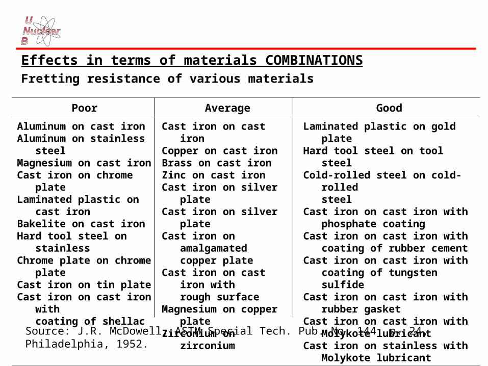
Effects in terms of materials COMBINATIONSFretting resistance of various materials
Source: J.R. McDowell, ASTM Special Tech. Pub. No. 144, p. 24, Philadelphia, 1952.
Poor Average Good
Aluminum on cast ironAluminum on stainless steelMagnesium on cast ironCast iron on chrome plateLaminated plastic on cast ironBakelite on cast ironHard tool steel on stainlessChrome plate on chrome plateCast iron on tin plateCast iron on cast iron with coating of shellac
Cast iron on cast ironCopper on cast ironBrass on cast ironZinc on cast ironCast iron on silver plateCast iron on silver plateCast iron on amalgamated copper plateCast iron on cast iron with rough surfaceMagnesium on copper plateZirconium on zirconium
Laminated plastic on gold plateHard tool steel on tool steelCold-rolled steel on cold- rolled steelCast iron on cast iron with phosphate coatingCast iron on cast iron with coating of rubber cementCast iron on cast iron with coating of tungsten sulfideCast iron on cast iron with rubber
gasketCast iron on cast iron with Molykote lubricantCast iron on stainless with Molykote lubricant
Prevention of Fretting Corrosion
• lubricate;
• avoid relative motion (add packing, etc.);
• increase relative motion to reduce attack severity;
• select materials (e.g., choose harder component).

STRESS CORROSIONSTRESS CORROSION

STRESS CORROSION (“Stress Corrosion Cracking” - SCC)
Under tensile stress, and in a suitable environment, some metals and
alloys crack . . . usually, SCC noted by absence of significant surface
attack . . . occurs in “ductile” materials.

“Transgranular” SCC (“TGSCC”)
Cross section of stress-corrosioncrack in stainless steel.
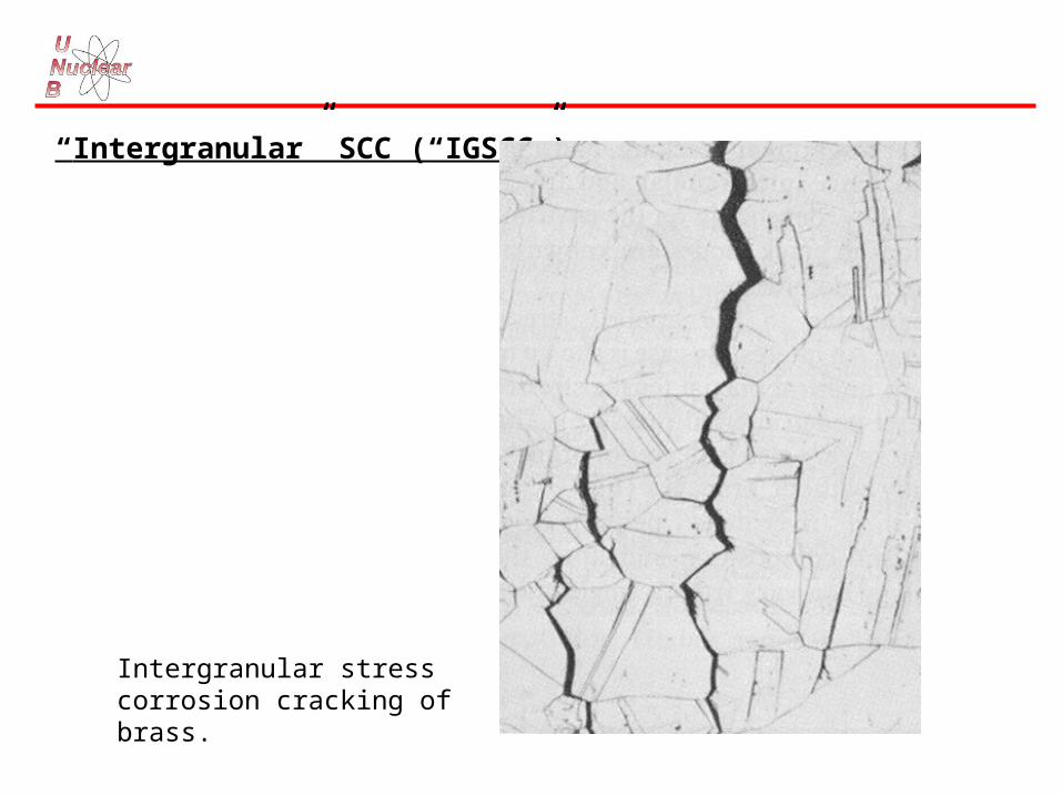
“Intergranular” SCC (“IGSCC”)
Intergranular stress corrosion cracking of brass.

Two original classic examples of SCC:• “season cracking” of brass;
• “caustic embrittlement” of CS;

“Season Cracking”
Occurs where brass case is crimped onto bullet, i.e., in area of high residual stress.
Common in warm, wet environments (e.g., tropics).
Ammonia (from decomposition of organic matter, etc.) must be present.
Season cracking of German ammunition.

“Caustic Embrittlement”Early steam boilers (19th and early 20th century) of riveted carbon steel. Both stationary and locomotive engines often exploded.
Examination showed:• cracks or brittle failures around rivet holes;• areas susceptible were cold worked by riveting (i.e., had high residual stresses);• whitish deposits in cracked regions were mostly caustic (i.e., sodium hydroxide
from chemical treatment of boiler water); • small leaks at rivets would concentrate NaOH and even dry out to solid. SCC
revealed by dye penetrant.
Carbon steel plate from a caustic storage tank failed by caustic embrittlement.

Factors important in SCC:
• environmental composition;
• stress;
• metal composition and microstructure;
• temperature;
e.g., brasses crack in NH3, not in Cl-;
SSs crack in Cl-, not in NH3;
SSs crack in caustic, not in H2SO4, HNO3, CH3COOH, . . . etc.
}necessary

STRESS
The greater the stress on the material, the quicker it will crack. (N.B.
in fabricated components, there are usually RESIDUAL STRESSES from cold
working, welding, surface treatment such as grinding or shot peening, etc., as
well as APPLIED STRESSES from the service, such as hydrostatic, vapour
pressure of contents, bending loads, etc.).
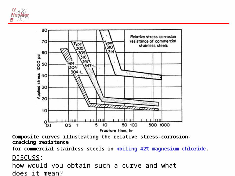
Composite curves illustrating the relative stress-corrosion-cracking resistancefor commercial stainless steels in boiling 42% magnesium chloride.
DISCUSS:how would you obtain such a curve and what does it mean?
The MAXIMUM stress you can apply before SCC is formed
(c.f. MINIMUM stress to be applied compressively to prevent SCC)
depends on alloy (composition and structure), temperature, and
environment composition.
Such “THRESHOLD” stresses may be between 10% & 70% of the yield
stress - Q.V.
N.B. residual stresses from welding steel can be close to the yield point.N.B. corrosion products can induce large stresses by “wedging”.

N.B. small-radius notch tip and even smaller-radius crack tip are STRESS RAISERS
A “wedging action” by corrosion products of 10 ksi (10,000 psi) can induce 300 ksi (300,000 psi) at the crack tip.

Corrosion product wedging “denting” of S.G. tubes in some PWRs . . .
Boiling in crevice concentrates impurities - can lead to acid + Cl- at seawater-cooled sites.
“Hour-glassing” of Alloy-600 tubes led to severe straining and cracking of tubes. Surrey PWR in U.S. was first to replace S.Gs., because of denting.
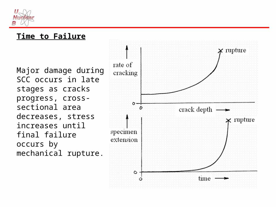
Time to Failure
Major damage during SCC occurs in late stages as cracks progress, cross-sectional area decreases, stress increases until final failure occurs by mechanical rupture.

Environmental Factors
No general pattern, SCC common in aqueous solutions, liquid metals; also found in fused salts, nonaqueous inorganic liquids . . .
N.B. Coriou (France) cracked Inconel-600 in pure water at 300C in 1959!!!
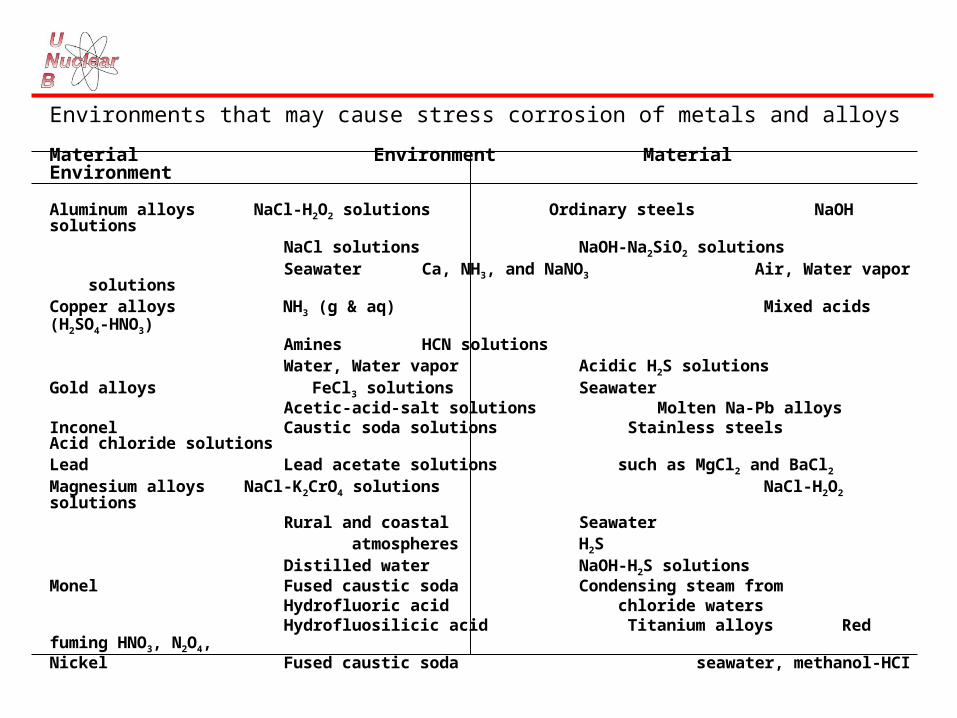
Environments that may cause stress corrosion of metals and alloys
Material Environment Material Environment
Aluminum alloys NaCl-H2O2 solutions Ordinary steels NaOH solutions NaCl solutions NaOH-Na2SiO2 solutions Seawater Ca, NH3, and NaNO3 Air, Water vapor solutions
Copper alloys NH3 (g & aq) Mixed acids (H2SO4-HNO3) Amines HCN solutions
Water, Water vapor Acidic H2S solutionsGold alloys FeCl3 solutions Seawater
Acetic-acid-salt solutions Molten Na-Pb alloysInconel Caustic soda solutions Stainless steels Acid chloride solutionsLead Lead acetate solutions such as MgCl2 and BaCl2
Magnesium alloys NaCl-K2CrO4 solutions NaCl-H2O2 solutions Rural and coastal Seawater atmospheres H2S Distilled water NaOH-H2S solutions
Monel Fused caustic soda Condensing steam from Hydrofluoric acid chloride waters Hydrofluosilicic acid Titanium alloys Red fuming HNO3, N2O4,
Nickel Fused caustic soda seawater, methanol-HCI

Increasing temperature accelerates SCC:
Most susceptible alloys crack 100C; Mg alloys crack at room temperature.
Alternate wetting and drying may aggravate SCC - accelerate crack growth (possibly because of increasing concentration of corrosive component as dryness is approached).
Effect of temperature on time for crack initiation in types 316 and 347 stainless steels in water containing 875 ppm NaCl.

Some Data for Recommending Service of CS or Ni Alloy in CausticNACE caustic soda chart super-imposed over the data on which it is based.
Area A:Carbon steel, no stress relief necessary; stress relieve welded steam-traced lines;
Area B:Carbon steel; stress relieve welds and bends;
Area C:Application of nickel alloys to be considered in this area; nickel alloy trim for valves in areas B and C.
Metallurgical Factors in IGSCC
In austenitic SS and Ni alloys, sensitization is of major importance in determining susceptibility to IGSCC . . . depletion of grain boundaries in Cr because of carbide precipitation makes them vulnerable to attack. e.g., IGSCC of recirculation piping in BWRs (type 304 SS) induced by 200 ppb dissolved oxygen in the otherwise pure H2O coolant resulted in a major replacement problem. Plants using L-grade experienced very much less SCC.
Al alloys (e.g., with Mg and Zn) are also susceptible to IGSCC because of precipitation within grain boundaries . . . Mg-rich precipitates can denude the grain boundaries of Mg, make them susceptible to attack in aqueous media.
N.B. In grain-boundary-precipitate mechanisms for inducing IGSCC, very local galvanic effects between precipitates and matrix are important:
• some precipitates are ANODIC;
• some precipitates are CATHODIC.
Grain boundary segregation of alloy constituents or impurities (without
precipitation of separate phases) can also induce IGSCC.
e.g., Mg enrichment of grain boundaries in Al alloys is a factor in IGSCC
- promotes local dissolution and hydrogen entry (maybe to form hydride, MgH);
- also . . . grain boundary enrichment of impurities and/or C in Fe-base alloys, Ni-base alloys and austenitic stainless steels can contribute to IGSCC;
- segregation of P, Si, S, N, B reported; only clear link with IGSCC reported for P in austenitic SS in oxidizing aqueous solutions, for P in ferritic alloys in nitrate and caustic solutions.
Transgranular SCC
Lattice structure in metal/alloy matrix important: dislocation emergence, movement along slip planes under stress, and similar factors that can disrupt passivating films, will promote dissolution of metal at highly localized and strained areas.
Irradiation-Assisted SCC (IASCC)
Since 1987, some in-reactor components have cracked in LWRs . . generally in core-support structures at the top of the vessel (austenitic SS, Ni alloys). More widespread in BWRs than PWRs . . . radiolytic chemical species (especially oxidizing radicals) seem to be the cause.
IASCC of Alloy-600 (Inconel) penetrations in several PWR vessel heads have led to leaks and boric-acid corrosion of RPV head steel (e.g., Davis Besse). Heads replaced.
Mechanism of SCC
SCC is very complex; probably no single mechanism, but several operating at the same time. Models (scientific descriptions) of mechanisms of two types:
• dissolution;
• mechanical fracture.
Dissolution Models of Crack Propagation
Major model is based on Film Rupture . . . (“slip-dissolution”) . . . high stresses at crack tip create local area of plastic deformation - ruptures passive films, exposed metal dissolves rapidly . . . some say periodic dissolution and re-passivation, some say crack tip always bare.

periodic rupture
Schematic representation of crack propagation by the film rupture model.
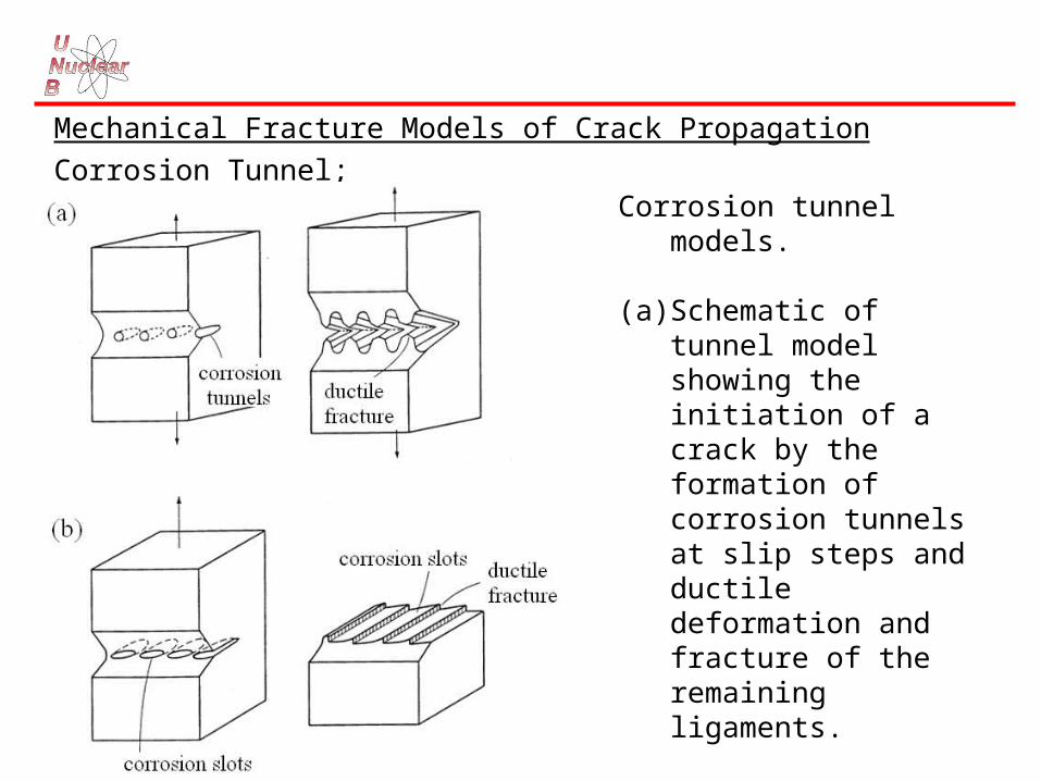
Mechanical Fracture Models of Crack Propagation
Corrosion Tunnel;Corrosion tunnel models.
(a) Schematic of tunnel model showing the initiation of a crack by the formation of corrosion tunnels at slip steps and ductile deformation and fracture of the remaining ligaments.
(b) Schematic diagram of the tunnel mechanism of SSC and flat slot formation.

• Adsorption of impurities at the crack tip promotes the nucleation of dislocations; • lead to shear-like fracture (seemingly brittle).
• Tarnish Rupture;Cracks propagate by alternate film growth and (brittle) film fracture, followed by rapid film formation over exposed metal.• Film-Induced Cleavage;
• thin film forms;• brittle crack initiates in layer;• crack moves from film into matrix;• crack continues through ductile matrix until it blunts and stops;• process repeats.
• Adsorption-Induced Brittle Fracture;Species adsorbing at crack tip alter inter-atomic bond strengths, lower stress required for fracture; propagation should be continuous.• Hydrogen Embrittlement;Cathodic processes involving hydrogen-ion reduction can inject H into matrix . . . this can embrittle metal, promote cracking . . . most likely in ferritic steels but also possible in Ni-base, Ti and Al alloys (contributes to SCC of carbon steel feeders at Point Lepreau …?).
Prevention of SCC
1. Lowering the stress below the threshold value if one exists. This may be done by annealing in the case of residual stresses, thickening the section, or reducing the load. Plain carbon steels may be stress-relief annealed at 590 to 650C, and the austenitic stainless steels are frequently stress-relieved at temperatures ranging from 820 to 930C.
2. Eliminating the critical environmental species by, for example, de-gasification, demineralization, or distillation.
3. Changing the alloy is one possible recourse if neither the environment nor stress can be changed. For example, it is common practice to use Inconel (raising the nickel content) when type 304 stainless steel is not satisfactory. Although carbon steel is less resistant to general corrosion, it is more resistant to stress-corrosion cracking than are the stainless steels. Thus, under conditions which tend to produce stress-corrosion cracking, carbon steels are often found to be more satisfactory than the stainless steels. For example, heat exchangers used in contact with seawater or brackish waters are often constructed of ordinary mild steel.

4. Applying cathodic protection to the structure with an external power supply or consumable anodes. Cathodic protection should only be used to protect installations where it is positively known that stress-corrosion cracking is the cause of fracture, since hydrogen embrittlement effects are accelerated by impressed cathodic currents.
5. Adding inhibitors to the system if feasible. Phosphates and other inorganic and organic corrosion inhibitors have been used successfully to reduce stress-corrosion cracking effects in mildly corrosive media. As in all inhibitor applications, sufficient inhibitor should be added to prevent the possibility of localized corrosion and pitting.
6. Coatings are sometimes used, and they depend on keeping the environment away from the metal - for example, coating vessels and pipes that are covered with insulation. In general, however, this procedure may be risky for bare metal.
7. Shot-peening (also known as shot-blasting) produces residual compressive stresses in the surface of the metal. Very substantial improvement in resistance to stress corrosion found as a result of peening with glass beads. Type 410 stainless was exposed to 3% NaCl at room temperature; type 304 to 42% MgCI2 at 150C; and aluminum alloy 7075-T6 to a water solution of K2Cr2O7-CrO3-NaCl at room temperature.
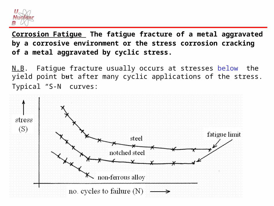
Corrosion Fatigue The fatigue fracture of a metal aggravated by a corrosive environment or the stress corrosion cracking of a metal aggravated by cyclic stress.
N.B. Fatigue fracture usually occurs at stresses below the yield point but after many cyclic applications of the stress.
Typical “S-N” curves:

Fatigue-fractured material often shows most of the fracture face shiny metallic, with the final area to fracture (mechanically by brittle fracture of a reduced cross-section) having a rough crystalline appearance . . .
If corrosion-fatigue occurs, the “shiny-metallic” area might be covered with corrosion products; BUT normal fatigue fractures may also develop corrosion products - depends on environment, stress pattern, etc.

N.B. In normal fatigue, the frequency of the stress cycles is not important. (can do accelerated fatigue tests at high frequency - the total number of cycles determines fatigue).
BUT in corrosion fatigue, low-cycle stresses are more damaging than high-frequency stresses.
Environment is important….e.g., in seawater:• Al bronzes and type 300 series SS lose 20-30% of normal fatigue resistance;• high-Cr alloys lose 60-70% resistance.
N.B. Cyclic loads mean lower allowable stresses, this must be designed into components; if there is also a corrosive environment, the allowable stresses are EVEN LOWER.
Prevention of Corrosion Fatigue
• change design so as to reduce stress and/or cycling.
• reduce stress by heat treatment (for residual stress), shot peening (to change surface residual stresses to COMPRESSIVE).
• use corrosion inhibitor with care!
• use coatings . . . electrodeposited
• Zn;
• Cr;
• Ni;
• Cu;
and
• nitrided layers (heating of steels in contact with N-containing material e.g., NH3, NaCN, etc.).

HYDROGEN DAMAGEHYDROGEN DAMAGE
HYDROGEN EFFECTS
Hydrogen can degrade metals by:
• hydrogen blistering;
• hydrogen embrittlement;
• decarburization;
• hydrogen attack.
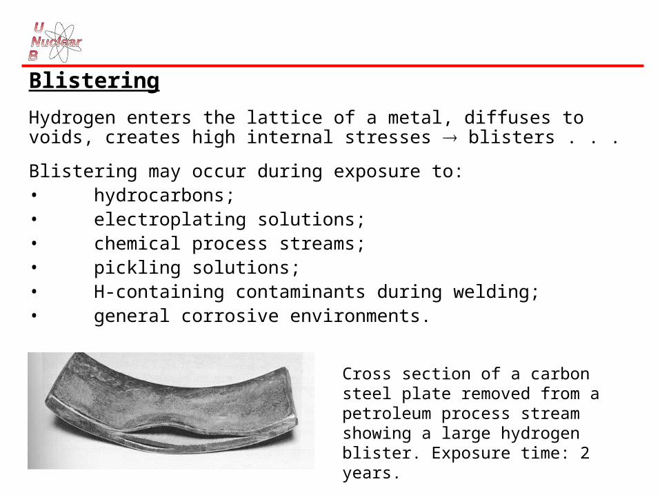
Blistering
Hydrogen enters the lattice of a metal, diffuses to voids, creates high internal stresses blisters . . .
Blistering may occur during exposure to: • hydrocarbons;• electroplating solutions;• chemical process streams;• pickling solutions;• H-containing contaminants during welding;• general corrosive environments.
Cross section of a carbon steel plate removed from a petroleum process stream showing a large hydrogen blister. Exposure time: 2 years.

Embrittlement
Similar to blistering . . . hydrogen enters metal lattice . . .BUT . . .interaction with metal lattice different. High-strength (and more brittle) steels are susceptible.
H-embrittlement different from SCC in nature of cracks . . . stress-corrosion cracks usually propagate anodically;

Hydride-forming metals are susceptible to H- embrittlement . . .e.g., Zr-alloy pressure tubes (in CANDUs) and fuel sheathing (in all water- cooled reactors) pick up hydrogen (or deuterium in heavy water ) by general corrosion. The hydrogen (D) migrates through the metal lattice to cool regions and to regions of high tensile stress - can precipitate as a separate phase - zirconium hydride.
These hydrides are themselves brittle, and crack, and the crack can propagate through the material, with more hydride progressively precipitating at the crack tip.
N.B. Enough hydride can precipitate to form a “hydride” blister . . . c.f. “hydrogen” blister.

N.B. The mechanism of hydrogen uptake by metals must involve ATOMIC HYDROGEN - molecular hydrogen cannot diffuse through metal lattices.
BUT . . . remember that molecular hydrogen may absorb and dissociate on metal surfaces.
Schematic illustration showing the mechanism of hydrogen blistering.

Decarburization and Hydrogen Attack
High temperature process - C or carbide in steels can react with gaseous hydrogen . . .
C + 2H2 CH4
Note that the reaction can occur with atomic H in the metal lattice . . .
C + 4H CH4
May crack the steel from high internal pressure.
May cause loss of strength as C disappears.

Prevention of Blistering
• use steels with few or no voids;
• use coatings;
• use inhibitors;
• remove impurities that can promote hydrogen evolution . . . S2- (particularly
bad), As, CN-, etc.;
• use different materials (Ni-base alloys have low diffusion rates for
hydrogen).
Prevention of Embrittlement
• reduce corrosion rate (inhibitors, coatings, etc.);
• change electroplating process to minimize H effects (voltage, current
density, bath composition, etc.);
• bake material to remove H;
• minimize residual stresses;
• use less susceptible material;
• maintain clean conditions during welding.


![ENTERGY NUCLEAR MANAGEMENT MANUAL ENN-DC-149 · - Erosion YOINm(3) Flow-accelerated corrosion YIT]/Nm(4) Ym/N[I](17) Microbiologically influenced corrosion (MIC) Selective leaching](https://static.fdocuments.in/doc/165x107/60843f4e021bfb1fe738e495/entergy-nuclear-management-manual-enn-dc-149-erosion-yoinm3-flow-accelerated.jpg)