Chapter 3 Features, advantages and applicability of CCTs 3.pdf · Chapter 3 . Features, advantages...
18
Chapter 3 Features, advantages and applicability of CCTs (Coal-Based Power Generating Technologies)
Transcript of Chapter 3 Features, advantages and applicability of CCTs 3.pdf · Chapter 3 . Features, advantages...

Chapter 3
Features, advantages and applicability of CCTs
(Coal-Based Power Generating Technologies)
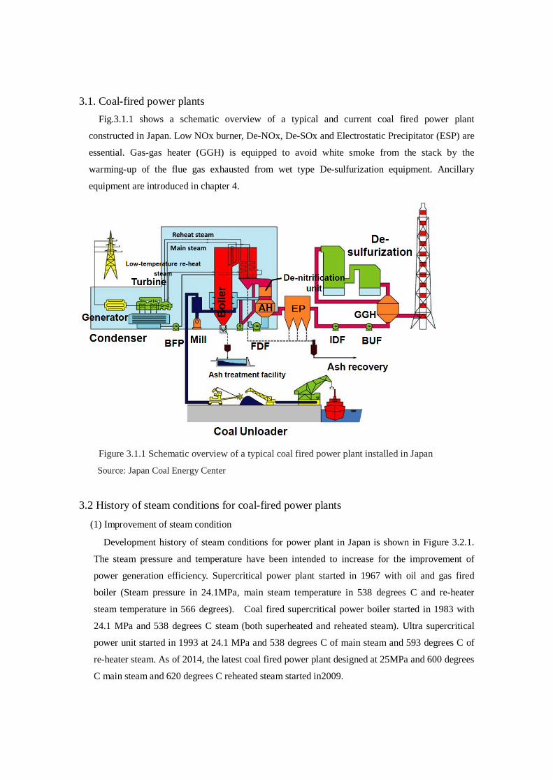
3.1. Coal-fired power plants Fig.3.1.1 shows a schematic overview of a typical and current coal fired power plant
constructed in Japan. Low NOx burner, De-NOx, De-SOx and Electrostatic Precipitator (ESP) are
essential. Gas-gas heater (GGH) is equipped to avoid white smoke from the stack by the
warming-up of the flue gas exhausted from wet type De-sulfurization equipment. Ancillary
equipment are introduced in chapter 4.
Figure 3.1.1 Schematic overview of a typical coal fired power plant installed in Japan
Source: Japan Coal Energy Center
3.2 History of steam conditions for coal-fired power plants
(1) Improvement of steam condition
Development history of steam conditions for power plant in Japan is shown in Figure 3.2.1.
The steam pressure and temperature have been intended to increase for the improvement of
power generation efficiency. Supercritical power plant started in 1967 with oil and gas fired
boiler (Steam pressure in 24.1MPa, main steam temperature in 538 degrees C and re-heater
steam temperature in 566 degrees). Coal fired supercritical power boiler started in 1983 with
24.1 MPa and 538 degrees C steam (both superheated and reheated steam). Ultra supercritical
power unit started in 1993 at 24.1 MPa and 538 degrees C of main steam and 593 degrees C of
re-heater steam. As of 2014, the latest coal fired power plant designed at 25MPa and 600 degrees
C main steam and 620 degrees C reheated steam started in2009.
Main steam
Reheat steam
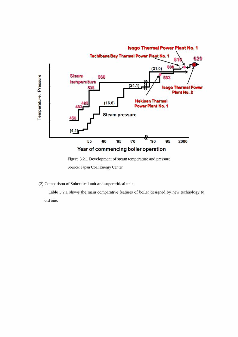
Figure 3.2.1 Development of steam temperature and pressure.
Source: Japan Coal Energy Center
(2) Comparison of Subcritical unit and supercritical unit
Table 3.2.1 shows the main comparative features of boiler designed by new technology to
old one.
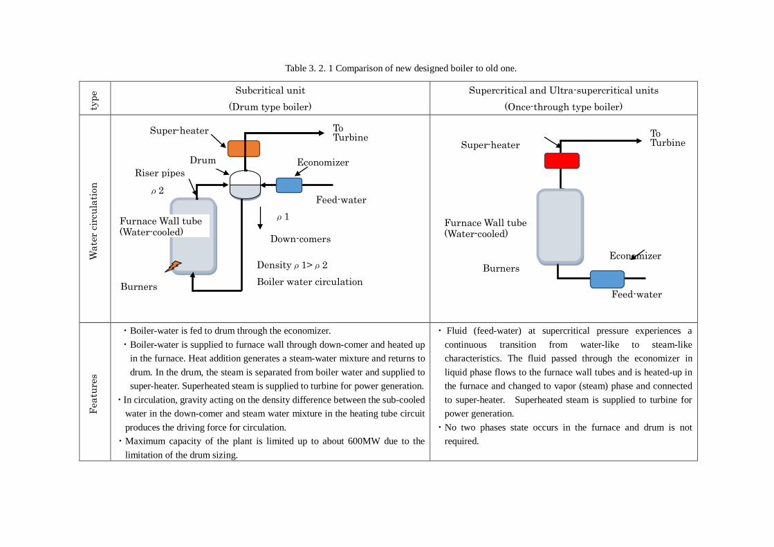
Table 3. 2. 1 Comparison of new designed boiler to old one.
type
Subcritical unit (Drum type boiler)
Supercritical and Ultra-supercritical units (Once-through type boiler)
Wat
er c
ircu
latio
n
Feat
ures
・Boiler-water is fed to drum through the economizer. ・Boiler-water is supplied to furnace wall through down-comer and heated up
in the furnace. Heat addition generates a steam-water mixture and returns to drum. In the drum, the steam is separated from boiler water and supplied to super-heater. Superheated steam is supplied to turbine for power generation.
・In circulation, gravity acting on the density difference between the sub-cooled water in the down-comer and steam water mixture in the heating tube circuit produces the driving force for circulation.
・Maximum capacity of the plant is limited up to about 600MW due to the limitation of the drum sizing.
・ Fluid (feed-water) at supercritical pressure experiences a continuous transition from water-like to steam-like characteristics. The fluid passed through the economizer in liquid phase flows to the furnace wall tubes and is heated-up in the furnace and changed to vapor (steam) phase and connected to super-heater. Superheated steam is supplied to turbine for power generation.
・No two phases state occurs in the furnace and drum is not required.
Furnace Wall tube (Water-cooled)
Riser pipes Drum
ρ2
ρ1
Down-comers
Densityρ1>ρ2 Boiler water circulation
To Turbine
Feed-water Furnace Wall tube (Water-cooled)
Burners
Super-heater
Burners
To Turbine
Feed-water
Furnace Wall tube (Water-cooled)
Super-heater
Economizer
Economizer
To Turbine
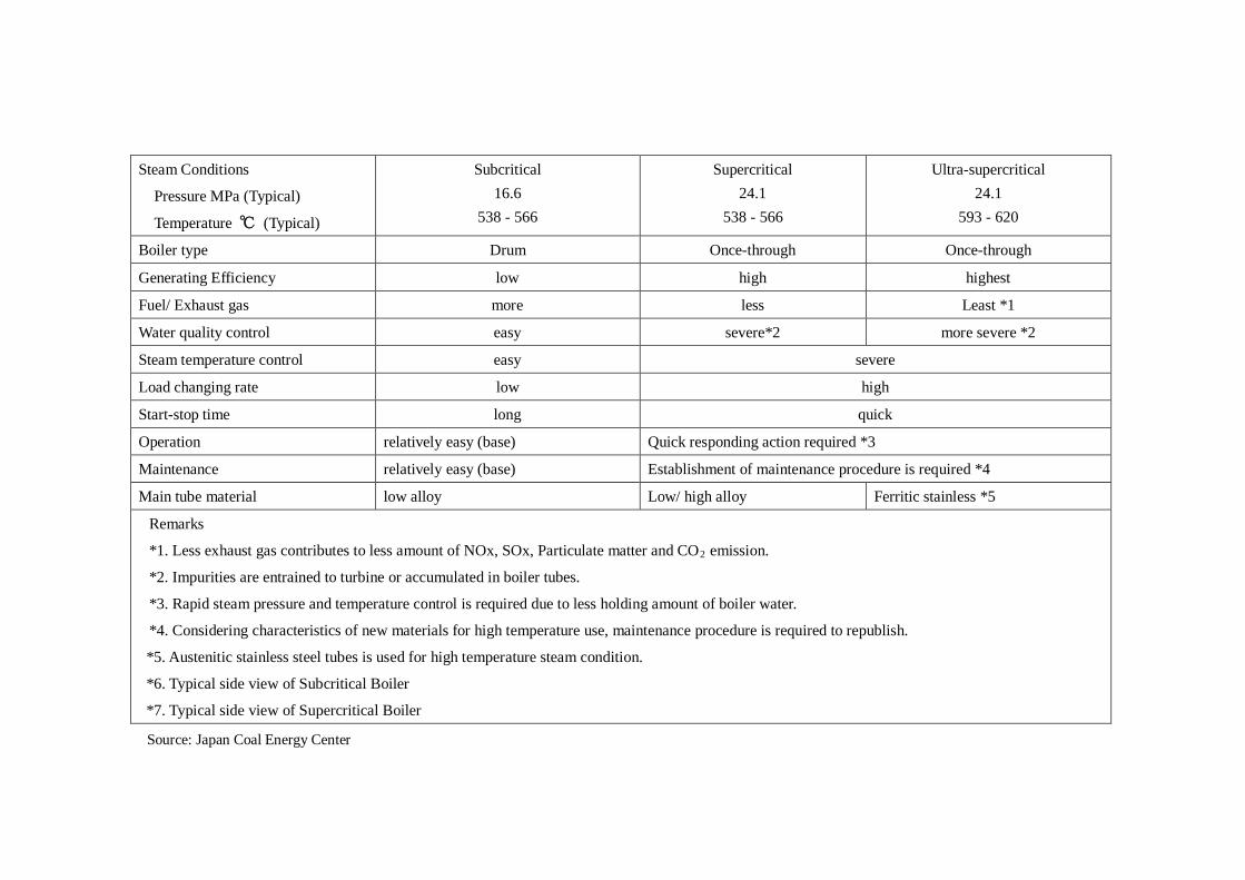
Steam Conditions
Pressure MPa (Typical)
Temperature ℃ (Typical)
Subcritical 16.6
538 - 566
Supercritical 24.1
538 - 566
Ultra-supercritical 24.1
593 - 620
Boiler type Drum Once-through Once-through
Generating Efficiency low high highest
Fuel/ Exhaust gas more less Least *1
Water quality control easy severe*2 more severe *2
Steam temperature control easy severe
Load changing rate low high
Start-stop time long quick
Operation relatively easy (base) Quick responding action required *3
Maintenance relatively easy (base) Establishment of maintenance procedure is required *4
Main tube material low alloy Low/ high alloy Ferritic stainless *5
Remarks
*1. Less exhaust gas contributes to less amount of NOx, SOx, Particulate matter and CO2 emission.
*2. Impurities are entrained to turbine or accumulated in boiler tubes.
*3. Rapid steam pressure and temperature control is required due to less holding amount of boiler water.
*4. Considering characteristics of new materials for high temperature use, maintenance procedure is required to republish.
*5. Austenitic stainless steel tubes is used for high temperature steam condition.
*6. Typical side view of Subcritical Boiler
*7. Typical side view of Supercritical Boiler
Source: Japan Coal Energy Center
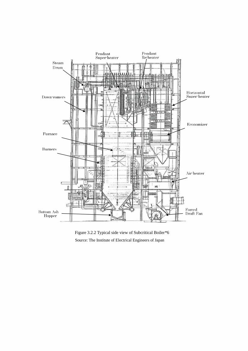
Figure 3.2.2 Typical side view of Subcritical Boiler*6
Source: The Institute of Electrical Engineers of Japan
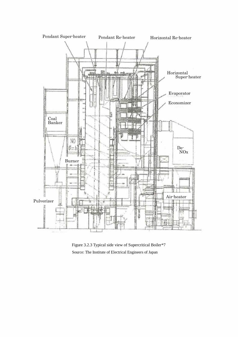
Figure 3.2.3 Typical side view of Supercritical Boiler*7
Source: The Institute of Electrical Engineers of Japan
Pendant Super-heater Pendant Re-heater Horizontal Re-heater
Horizontal Super-heater
Evaporator
De- NOx
Economizer
Air-heater
Coal Banker
Burner
Pulverizer
3.3 Ultra-supercritical coal-fired power plants In the 90th, National project was started to develop 600 degrees C class coal fired power plants to
improve the thermal efficiency. First USC (≥24.1 MPa and 593 ℃) in Japan was built in 1993
whose capacity was 700MW.
Since then the steam conditions in USC for all coal fired power plants have been adopted in
Japanese power station. Furthermore the development for the application of higher steam
temperature has been proceeded and as of 2014, the highest super-heater and re-heater steam
temperatures are in 600 ℃ and 620 ℃ respectively.
. All of them have been operating with a high efficiency and high availability.
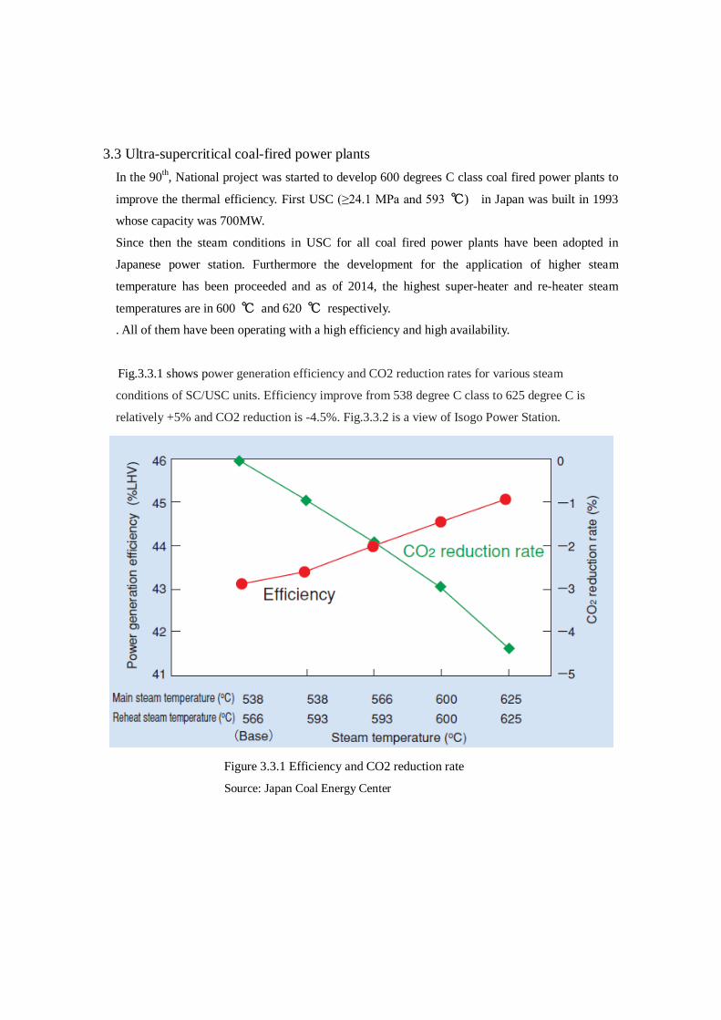
Fig.3.3.1 shows power generation efficiency and CO2 reduction rates for various steam
conditions of SC/USC units. Efficiency improve from 538 degree C class to 625 degree C is
relatively +5% and CO2 reduction is -4.5%. Fig.3.3.2 is a view of Isogo Power Station.
Figure 3.3.1 Efficiency and CO2 reduction rate
Source: Japan Coal Energy Center
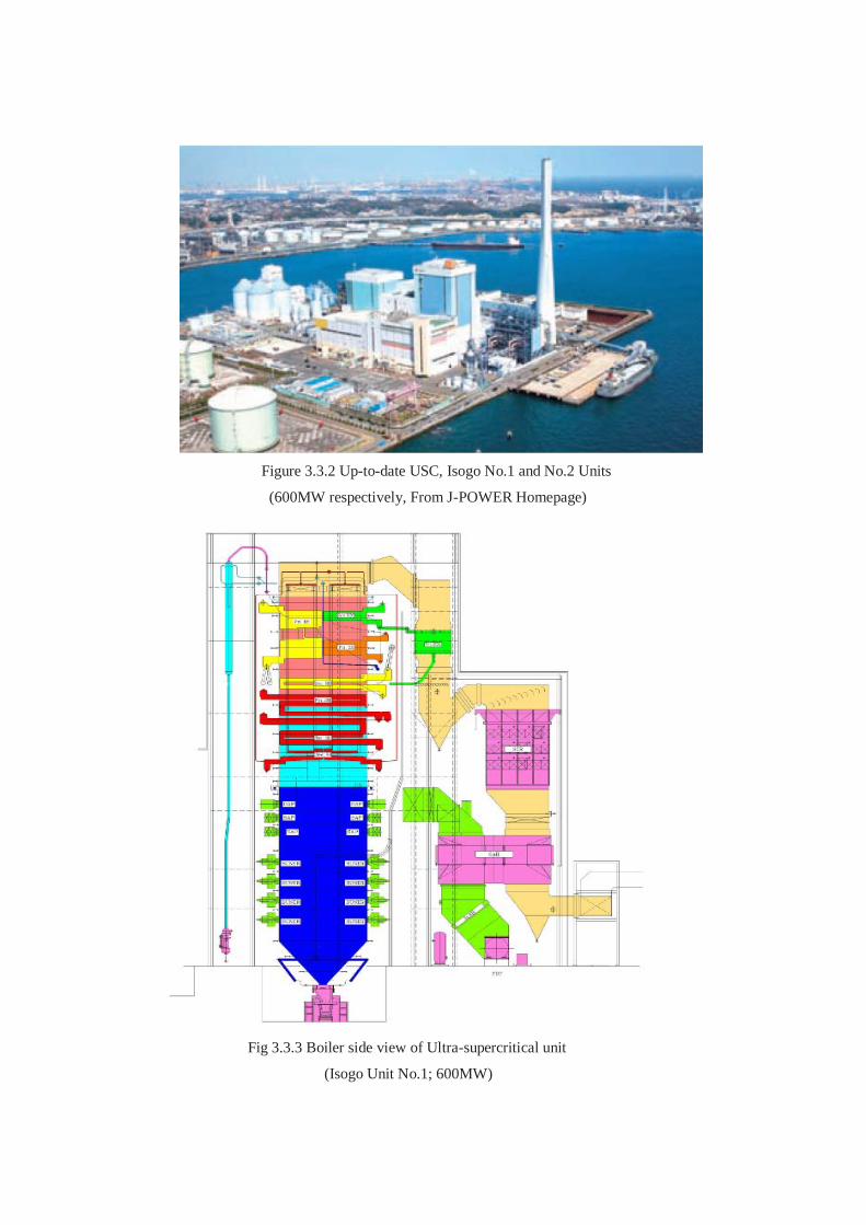
Figure 3.3.2 Up-to-date USC, Isogo No.1 and No.2 Units
(600MW respectively, From J-POWER Homepage)
Fig 3.3.3 Boiler side view of Ultra-supercritical unit
(Isogo Unit No.1; 600MW)
For the next step, the study for a 700 degree C class USC power plant started in 1998. It is called
as A-USC (Advanced USC) whose targeted net efficiency is around 50% (LHV basis).
3.4 Integrated Coal Gasification Combined Cycle (IGCC) (1) General
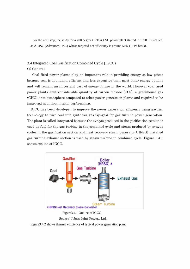
Coal fired power plants play an important role in providing energy at low prices because coal is abundant, efficient and less expensive than most other energy options and will remain an important part of energy future in the world. However coal fired power plants emit considerable quantity of carbon dioxide (CO2), a greenhouse gas (GHG), into atmosphere compared to other power generation plants and required to be improved in environmental performance. IGCC has been developed to improve the power generation efficiency using gasifier technology to turn coal into synthesis gas (syngas) for gas turbine power generation. The plant is called integrated because the syngas produced in the gasification section is used as fuel for the gas turbine in the combined cycle and steam produced by syngas cooler in the gasification section and heat recovery steam generator (HRSG) installed gas turbine exhaust section is used by steam turbine in combined cycle. Figure 3.4-1 shows outline of IGCC.
Figure3.4.1 Outline of IGCC
Source: Joban Joint Power., Ltd.
Figure3.4.2 shows thermal efficiency of typical power generation plant.
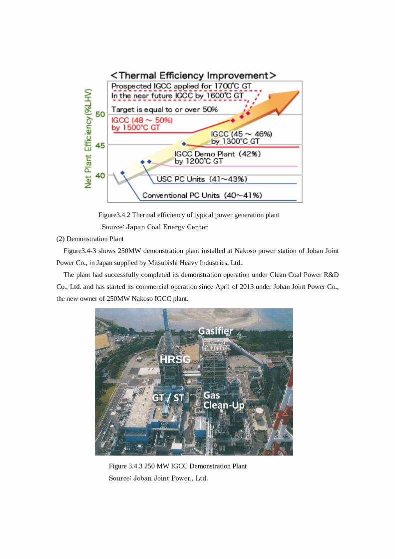
Figure3.4.2 Thermal efficiency of typical power generation plant
Source: Japan Coal Energy Center (2) Demonstration Plant
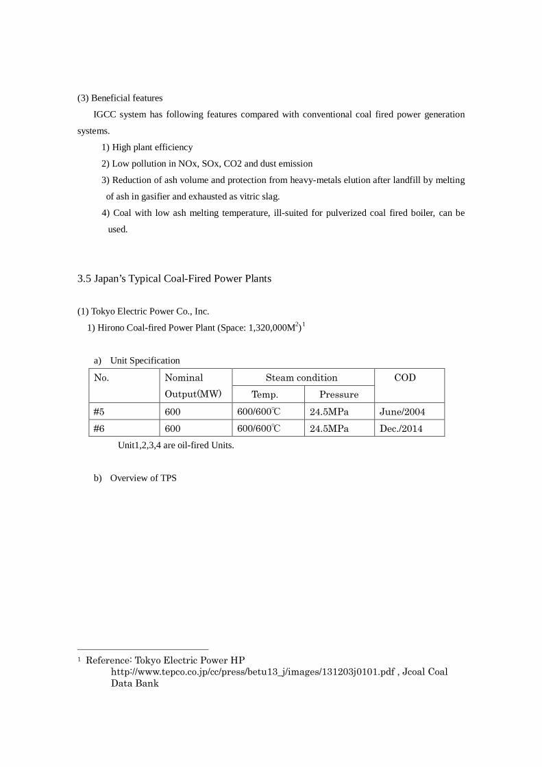
Figure3.4-3 shows 250MW demonstration plant installed at Nakoso power station of Joban Joint
Power Co., in Japan supplied by Mitsubishi Heavy Industries, Ltd..
The plant had successfully completed its demonstration operation under Clean Coal Power R&D
Co., Ltd. and has started its commercial operation since April of 2013 under Joban Joint Power Co.,
the new owner of 250MW Nakoso IGCC plant.
Figure 3.4.3 250 MW IGCC Demonstration Plant
Source: Joban Joint Power., Ltd.
GT / ST
HRSG
Gas Clean-Up
Gasifier
(3) Beneficial features
IGCC system has following features compared with conventional coal fired power generation
systems.
1) High plant efficiency
2) Low pollution in NOx, SOx, CO2 and dust emission
3) Reduction of ash volume and protection from heavy-metals elution after landfill by melting
of ash in gasifier and exhausted as vitric slag.
4) Coal with low ash melting temperature, ill-suited for pulverized coal fired boiler, can be
used.
3.5 Japan’s Typical Coal-Fired Power Plants (1) Tokyo Electric Power Co., Inc.
1) Hirono Coal-fired Power Plant (Space: 1,320,000M2)1
a) Unit Specification
No. Nominal Output(MW)
Steam condition COD Temp. Pressure
#5 600 600/600℃ 24.5MPa June/2004 #6 600 600/600℃ 24.5MPa Dec./2014 Unit1,2,3,4 are oil-fired Units.
b) Overview of TPS
1 Reference: Tokyo Electric Power HP
http://www.tepco.co.jp/cc/press/betu13_j/images/131203j0101.pdf , Jcoal Coal Data Bank
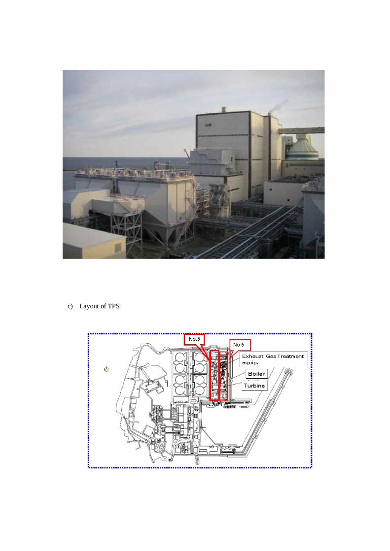
c) Layout of TPS
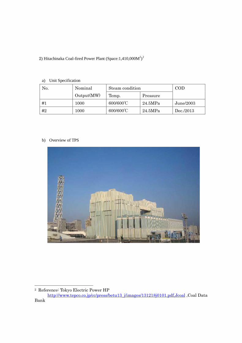
2) Hitachinaka Coal-fired Power Plant (Space:1,410,000M2)2
a) Unit Specification
No. Nominal Output(MW)
Steam condition COD Temp. Pressure
#1 1000 600/600℃ 24.5MPa June/2003 #2 1000 600/600℃ 24.5MPa Dec./2013 b) Overview of TPS
2 Reference: Tokyo Electric Power HP http://www.tepco.co.jp/cc/press/betu13_j/images/131218j0101.pdf,Jcoal ,Coal Data Bank
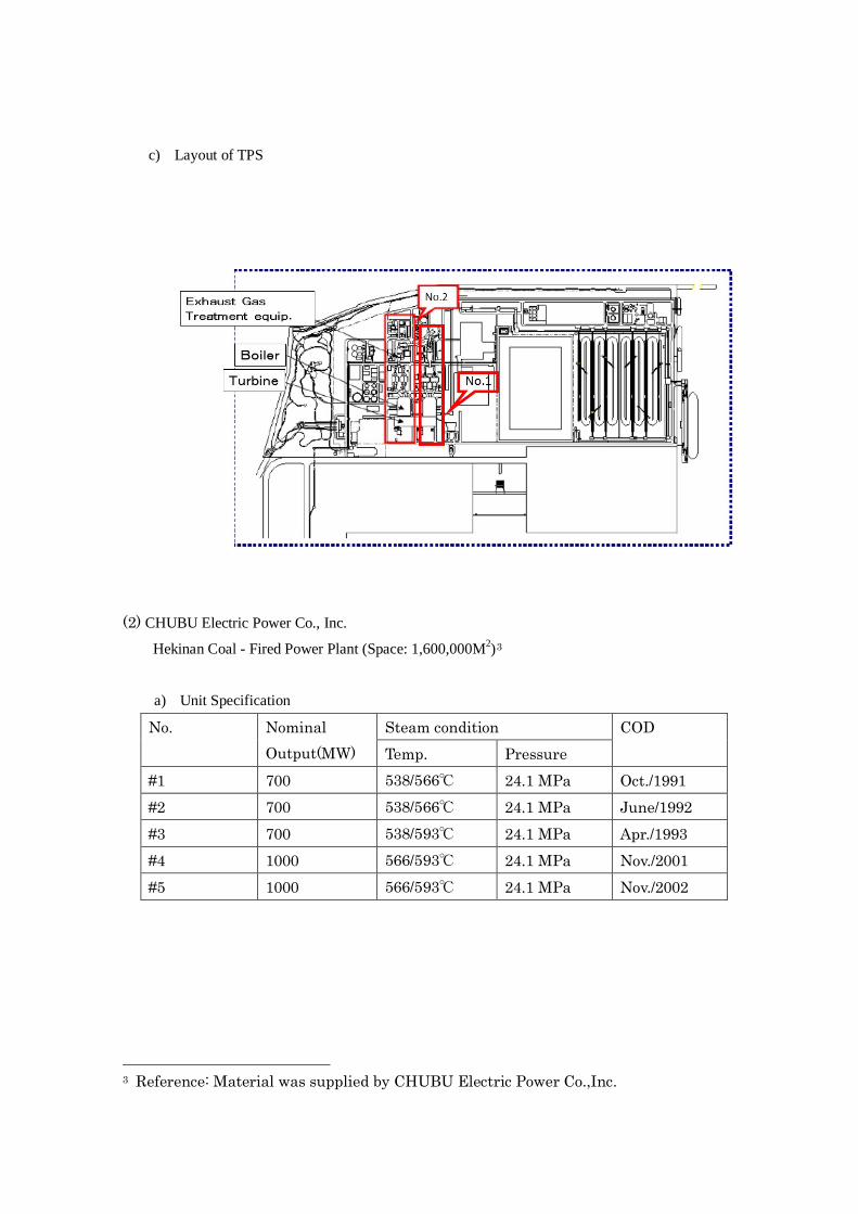
c) Layout of TPS
(2) CHUBU Electric Power Co., Inc.
Hekinan Coal - Fired Power Plant (Space: 1,600,000M2)3
a) Unit Specification
No. Nominal Output(MW)
Steam condition COD Temp. Pressure
#1 700 538/566℃ 24.1 MPa Oct./1991 #2 700 538/566℃ 24.1 MPa June/1992 #3 700 538/593℃ 24.1 MPa Apr./1993 #4 1000 566/593℃ 24.1 MPa Nov./2001 #5 1000 566/593℃ 24.1 MPa Nov./2002
3 Reference: Material was supplied by CHUBU Electric Power Co.,Inc.
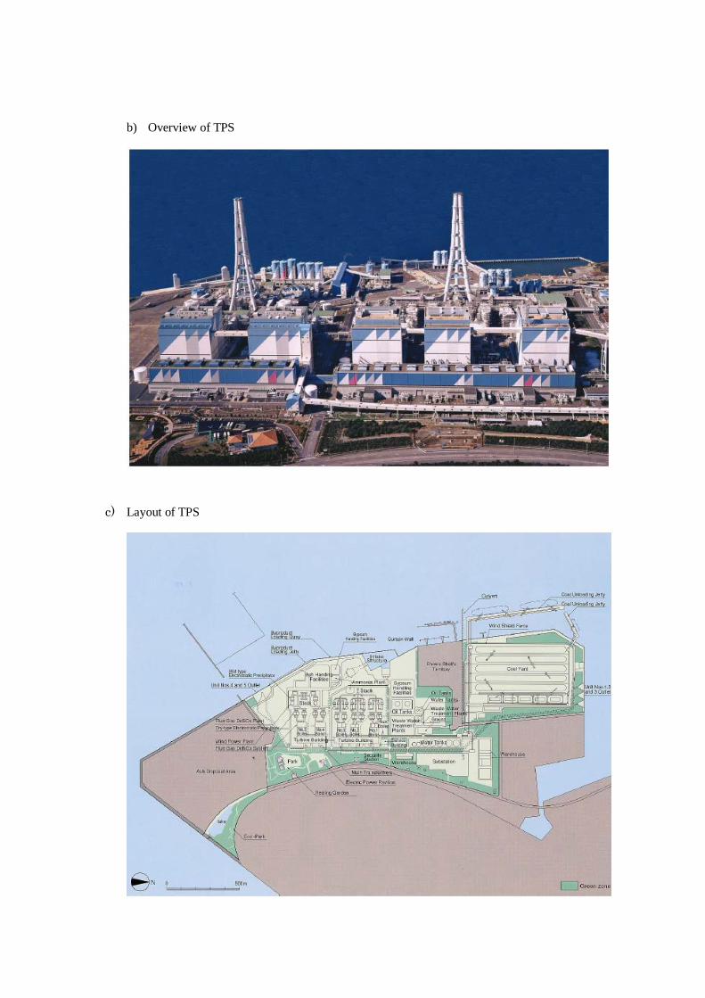
b) Overview of TPS
c) Layout of TPS
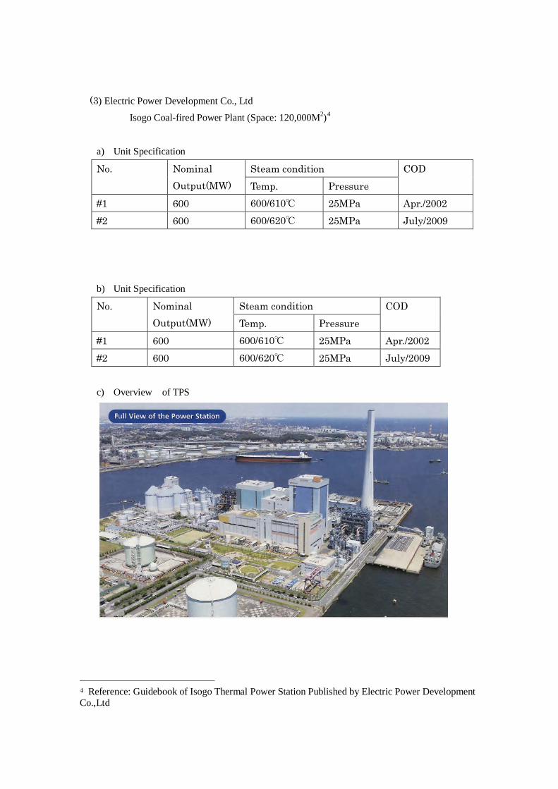
(3) Electric Power Development Co., Ltd
Isogo Coal-fired Power Plant (Space: 120,000M2)4
a) Unit Specification
No. Nominal Output(MW)
Steam condition COD Temp. Pressure
#1 600 600/610℃ 25MPa Apr./2002 #2 600 600/620℃ 25MPa July/2009
b) Unit Specification
No. Nominal Output(MW)
Steam condition COD Temp. Pressure
#1 600 600/610℃ 25MPa Apr./2002 #2 600 600/620℃ 25MPa July/2009
c) Overview of TPS
4 Reference: Guidebook of Isogo Thermal Power Station Published by Electric Power Development Co.,Ltd
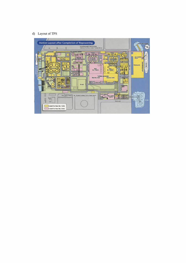
d) Layout of TPS


![PMR Science Test (CCTS)[1]](https://static.fdocuments.in/doc/165x107/543a1d31afaf9fbd2e8b58f5/pmr-science-test-ccts1.jpg)