![INDEX []€¦ · INDEX SI.NO EXPERIMENT DETAILS PAGE 1 ... STUDY AND USE OF HYDRAULIC ELEMENTS 22 6 ... connected from the FRL unit.](https://static.fdocuments.in/doc/165x107/5b5b9c827f8b9a01748e6ce7/index-index-sino-experiment-details-page-1-study-and-use-of-hydraulic.jpg)
CHAPTER 3 EXPERIMENT DETAILS AND...
12
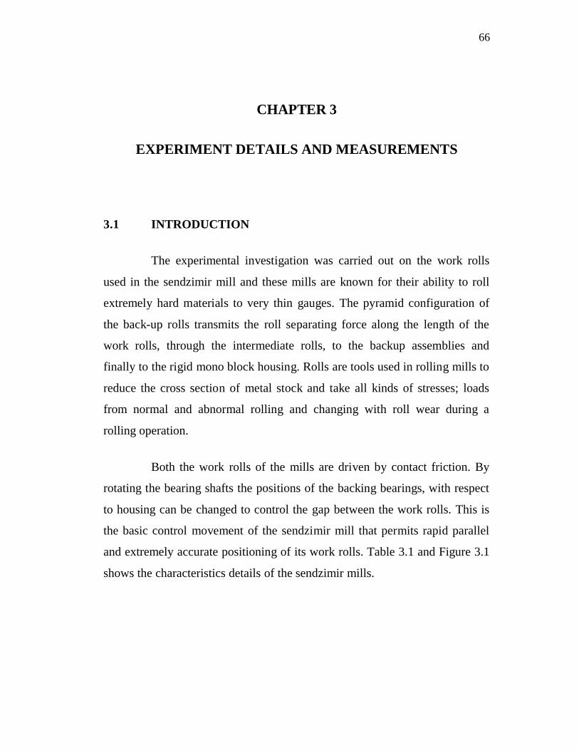
66 CHAPTER 3 EXPERIMENT DETAILS AND MEASUREMENTS 3.1 INTRODUCTION The experimental investigation was carried out on the work rolls used in the sendzimir mill and these mills are known for their ability to roll extremely hard materials to very thin gauges. The pyramid configuration of the back-up rolls transmits the roll separating force along the length of the work rolls, through the intermediate rolls, to the backup assemblies and finally to the rigid mono block housing. Rolls are tools used in rolling mills to reduce the cross section of metal stock and take all kinds of stresses; loads from normal and abnormal rolling and changing with roll wear during a rolling operation. Both the work rolls of the mills are driven by contact friction. By rotating the bearing shafts the positions of the backing bearings, with respect to housing can be changed to control the gap between the work rolls. This is the basic control movement of the sendzimir mill that permits rapid parallel and extremely accurate positioning of its work rolls. Table 3.1 and Figure 3.1 shows the characteristics details of the sendzimir mills.
Transcript of CHAPTER 3 EXPERIMENT DETAILS AND...
66
CHAPTER 3
EXPERIMENT DETAILS AND MEASUREMENTS
3.1 INTRODUCTION
The experimental investigation was carried out on the work rolls
used in the sendzimir mill and these mills are known for their ability to roll
extremely hard materials to very thin gauges. The pyramid configuration of
the back-up rolls transmits the roll separating force along the length of the
work rolls, through the intermediate rolls, to the backup assemblies and
finally to the rigid mono block housing. Rolls are tools used in rolling mills to
reduce the cross section of metal stock and take all kinds of stresses; loads
from normal and abnormal rolling and changing with roll wear during a
rolling operation.
Both the work rolls of the mills are driven by contact friction. By
rotating the bearing shafts the positions of the backing bearings, with respect
to housing can be changed to control the gap between the work rolls. This is
the basic control movement of the sendzimir mill that permits rapid parallel
and extremely accurate positioning of its work rolls. Table 3.1 and Figure 3.1
shows the characteristics details of the sendzimir mills.
67
Table 3.1 Characteristics of sendzimir mill rolls
Diameter (mm)Type of Rolls No. of
rolls Maximum MinimumLength(mm)
Work rolls 2 69 56 1530
First Intermediate 4 104 94 1424
Second Intermediate(Drive) 4 175 169 1380
Second intermediate 2 175 169 1344
Backup rolls each providedwith roller bearing 8 300 298
Figure 3.1 Schematic diagram of Sendzimir rolling mill

68
3.2 MACHINE
Experimental investigations have been carried out with varying
depth of cut, feed, speeds and number of passes for rough work rolls and for
the finish work rolls varying the dressing parameters also been included to
obtain fine finish in a roll grinder. For the attainment of good surface finish
with high hardness, a SHIBAURA roll grinding machine as shown in
Figure 3.2 with silicon carbide grinding wheel for finish work rolls and self
sharpening wheel for rough work rolls is employed. The roll grinder selected
is a semi-automatic machine and commonly used in steel rolling industries. In
this study, the parameters are varied according to an orthogonal array’s used
in different experimental conditions based on Design of Experiments. The
specification of grinding machine is given in the Table 3.2. Both rough and
finish rolls regularly redressed to rebuild the desired shape and to eliminate
the worm, fire cracked and fatigued surface.
Figure 3.1 Toshiba/Shibaura Sendzimer Roll Grinder

69
Table 3.2 Specification of Work Roll Grinding Machine
TOSHIBA/SHIBAURA SENDZIMER ROLL GRINDER
CAPACITY:
Max. crown and concavity on diameter: 0.02"
Swing over Bed Maximum: 8.46" (215mm)
Max. Overall Roll Length: 57" w/Long Center, 60" w/Short
Max. Length Between Centers: 78.8"
Max. Roll Weight: 440 lbs.
HEADSTOCK:
Speed of work (continuous): 60-300 rpm
Roll speeds, DC Variable: 60-300 rpm
TABLE:
Traverse speed (continuous): 2" - 200" min
WHEELHEAD:
Wheel speed (continuous): 300 - 1,800 rpm
Wheel size (diameter x width x hole): 14" x 1.5" x 5"
Spindle Speeds, DC Variable: 300-2000 rpm
Spindle Horsepower: 5
BACKREST:
Supportable journal diameter: 1.58" - 3.93"

70
3.3 WORK ROLL MATERIAL
The rough and finish work rolls are made of High carbon high
chromium D2 forged and hardened steel. These work rolls are produced from
electroslag refined steel and is forged on a 3000 tonne or 1000 tonne open die
forge. The forgings are immediately annealed to remove internal stresses
incurred during the forging processes. The forged work rolls then hardened up
to HRC 60.
3.3.1 Estimation of Chemical Composition
Chemical composition of the work roll materials is analyzed with
optical emission spectrometer (Figure 3.3). Sample preparation is extremely
important when analyzing samples in a spectro-lab. The work roll materials
are generally ground using a band or disc grinder. A 60 grit paper is
recommended. The spectrometer works on the principle of optical emission,
and its specifications are given in Table 3.3.The chemical composition of
work roll material is presented in the Table 3.4.Thermo-Mechanical
properties is presented in the Table 3.5.
Table 3.3 Specification of Optical Emission Spectrometer
Model : Spectrolab
Power details
Voltage -220 V AC , Frequency - 50 Hz, Power- 1.2 KVA
Argon supply - Quality 4.8 Argon- 300 liters/hr
Environmental condition

71
Table 3.4 Chemical composition of the work roll material
Table 3.5 Thermo-Mechanical Properties of the work roll
Figure 3.3 Spectrolab - Optical Emission Spectrometer
Carbon - 1.4 % - 1.6% Cobalt - Max. 1%
Chromium - 11% - 13% Manganese - Max. 0.6%
Molybdenum - 0.7% - 1.2% Phosphorus - Max. 0.03%
Sulfur - Max 0.03% Silicon - Max. 0.6%
Vanadium - Max 1.1%
Thermal Expansion : 10.4 x 10⁻⁶ at 20-100oC
Density : 7700 kg/m3 at 25°C
Poissions ratio : 0.27-0.30 at 25°C
Elastic Modulus : 190-210 Gpa at 25°C
72
3.4 SELECTION OF GRINDING WHEEL
Two problems, wheel glazing and wheel loading occur in grinding
process due to wrong selection of grinding wheel or improper cutting
conditions. Wheel glazing refers to the conditions when the grains are worn
down to the level of bond and held for too long for grinding the material. The
problem can be remedied either by changing the wheel or by changing the
cutting conditions. Wheel loading occurs when work piece chips are
embedded in the cutting face of the wheel, which reduces the effective depth
of penetration of the wheel abrasive into the work surface and thereby
reducing the rate of cutting. Wheel loading is aggravated by the presence of
small voids on the face of the grinding wheel. This can be cured by increasing
the wheel speed or using different wheel even.
Thus, the selection of grinding wheel for correct, continuous
efficient cutting demands the correct selection of the type of abrasive, the size
of grains, and the type of bonding agents and its strength and the size of
voids. Further, the behaviour of the grinding wheel is influenced by the work
piece materials, cutting speed, depth of cut, feed rate and the dressing
parameters.
Abrasives like Aluminium oxide and Silicon carbide have high
hardness in comparison to hardened steel and thus can be used for metal
removal by plastic deformation. The cutting tool materials have to be harder
for material removal by plastic deformation and also to maintain its shape and
for less wear. Work rolls used in this investigations having a hardness of HRC
60, length of work rolls are about 1630mm and diameter varies from 56mm to
68mm.To grind these work rolls, the grinding wheels must possess high
hardness, self- sharpening characteristics to avoid thermal damages on work
rolls and imparts uniform abrasive actions throughout the length of the work
rolls. For these reasons, in this experimental investigation, a self-sharpening

73
black silicon carbide grinding wheel was selected and used to grind the rough
work rolls. Green silicon carbide grinding wheel with fine grain sizes was
used to grind the finish work rolls, which require higher surface finish as
compare with rough work rolls. The specifications of the grinding wheels
used in this work are reported in the Table 3.6.
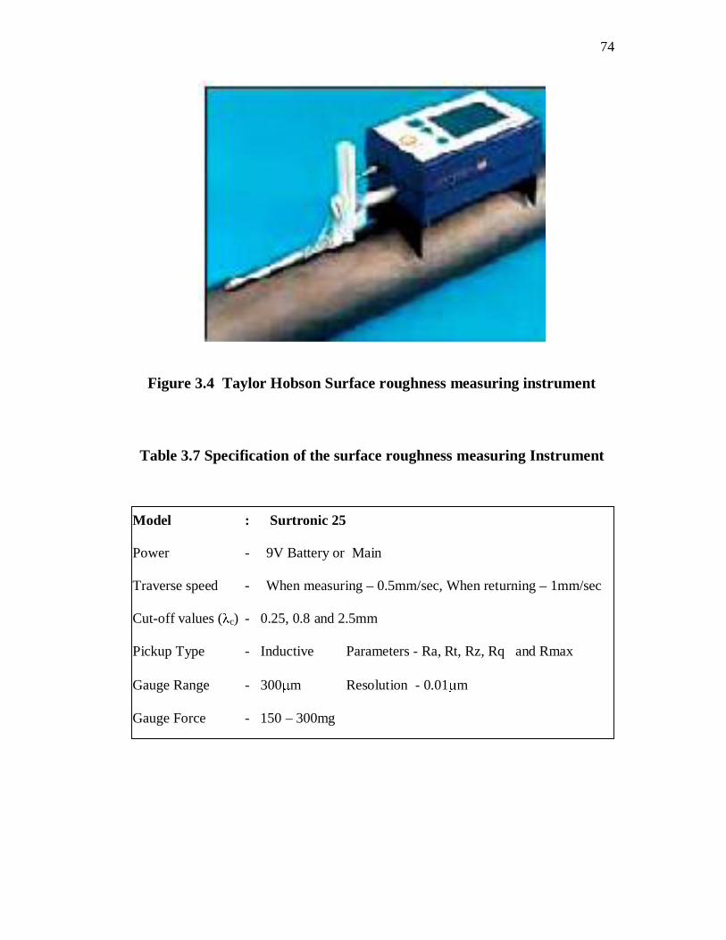
3.5 MEASUREMENT OF SURFACE ROUGHNESS
The surface roughness of the grounded work rolls is measured using
Taylor Hobson’s surtronic 25 with a diamond stylus tip of radius 5 m. It
measures Ra value at a touch of button and shows the results on a LCD
window. Figure 3.4 shows the method of measurement using this instrument
provided with roll and bore fixture. Table 3.7 shows the specification of the
instrument.
Table 3.6 Specification of the Grinding Wheels
Specification of SiC grinding wheel(Black)
Wheel diameter – 610mm
Wheel width – 76mm
Internal Diameter – 305mm
Abrasive – Silicon Carbide
Wheel grade – C60E7B14
Specification of SiC grinding wheel(Green)
Wheel diameter – 610mm
Wheel width – 76mm
Internal Diameter – 305mm
Abrasive – Silicon Carbide
Wheel grade – GC120H8BF09
74
Figure 3.4 Taylor Hobson Surface roughness measuring instrument
Table 3.7 Specification of the surface roughness measuring Instrument
Model : Surtronic 25
Power - 9V Battery or Main
Traverse speed - When measuring – 0.5mm/sec, When returning – 1mm/sec
Cut-off values ( c) - 0.25, 0.8 and 2.5mm
Pickup Type - Inductive Parameters - Ra, Rt, Rz, Rq and Rmax
Gauge Range - 300 m Resolution - 0.01 m
Gauge Force - 150 – 300mg

75
3.6 MEASUREMENT OF POWER AT GRINDING WHEEL
SPINDLE
A Digital Clamp Power Meter (DCPM) is used to take the
measurements of grinding power requirement. During grinding operation, the
power meter is attached to the electric cables of the grinding wheel spindle
motor. Figure 3.5 shows the Digital power clamp meter and its specification is
reported in the Table 3.8.
Figure 3.5 Digital Clamp Power Meter
Table 3.8 Specification of the Digital Clamp power Meter
Model : DPM 035
DC Current Ranges : 35A,350A,1000A,
AC Current Ranges : 35A,350A,1000A,
Active Power Ranges : 3.5kW,35kW,350kW,
Apparent Power Ranges : 3.5k,35k,350kVar,±(2%+5dgts)
AC Voltage (45-400Hz) Ranges : 350V,600V,
DC Voltage Ranges : 350V,600V,
76
3.7 MEASUREMENT OF HARDNESS OF WORK ROLL
MATERIAL
The measurement of surface hardness of the work roll material is
done with the use of Rockwell hardness tester. It works on the principle that
the depth of penetration varies with the hardness of material. The higher the
hardness, the smaller will be the depth of penetration and vice-versa. In this
test the depth of penetration is not measured, instead of the hardness value can
be read directly on a dial attached to the tester. A 120 degree diamond cone
also known as Brale indenter with a major load of 60kg is used in the
measurement. For this combination of indenter and load, ‘C’ scale readings
are taken.
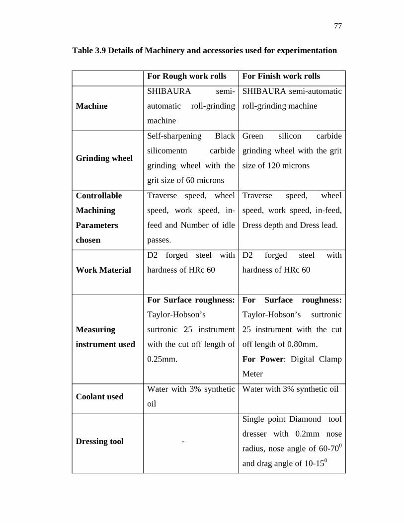
3.8 Experiment Details
Table 3.9 shows the details of machinery used, grinding wheel,
parameters considered, work material, measuring instruments, coolant and
dressing tool used for experimentation with rough and finish work rolls.
77
Table 3.9 Details of Machinery and accessories used for experimentation
For Rough work rolls For Finish work rolls
Machine
SHIBAURA semi-
automatic roll-grinding
machine
SHIBAURA semi-automatic
roll-grinding machine
Grinding wheel
Self-sharpening Black
silicomentn carbide
grinding wheel with the
grit size of 60 microns
Green silicon carbide
grinding wheel with the grit
size of 120 microns
Controllable
Machining
Parameters
chosen
Traverse speed, wheel
speed, work speed, in-
feed and Number of idle
passes.
Traverse speed, wheel
speed, work speed, in-feed,
Dress depth and Dress lead.
Work Material
D2 forged steel with
hardness of HRc 60
D2 forged steel with
hardness of HRc 60
Measuring
instrument used
For Surface roughness:
Taylor-Hobson’s
surtronic 25 instrument
with the cut off length of
0.25mm.
For Surface roughness:
Taylor-Hobson’s surtronic
25 instrument with the cut
off length of 0.80mm.
For Power: Digital Clamp
Meter
Coolant usedWater with 3% synthetic
oil
Water with 3% synthetic oil
Dressing tool -
Single point Diamond tool
dresser with 0.2mm nose
radius, nose angle of 60-700
and drag angle of 10-150