Chapter 3 Envelope materials - IKIU
76
Materials for subsurface land drainage systems 21 Chapter 3 Envelope materials Porous material placed around a subsurface drain, to protect the drain from sedimentation and improve its hydraulic performance, should be referred to as a drain envelope. It is worthwhile to distinguish between the definition and function of an envelope and that of a filter. During the early development of design criteria for drain envelopes, existing filter criteria were often used as a basis for research. Hence, the word ‘filter’ is often mistakenly used in reference to drain envelopes. A filter is by definition ‘a porous substance through which a gas or liquid is passed to separate out matter in suspension’ (Merriam-Webster, 1993). Filtration also is defined as ‘the restraining of soil or other particles subjected to hydraulic forces while allowing the passage of fluids’ (ISO 10318, 1990). Hence, a filter, used as a drain envelope, would eventually become clogged because particulate matter would be deposited on or in it, reducing its permeability. Envelopes have the task to improve the permeability around the pipe, and act as permeable constraints to impede entry of damaging quantities of soil particles and soil aggregates into drainpipes. Yet the majority of small particles of soil material and organic matter, suspended in water moving toward a drain, will actually pass through a properly selected and installed drain envelope without causing clogging. The relatively coarse envelope material placed around the drain should stabilize the soil mechanically and hydraulically, but should not act as a filter. In addition to the functions described above, drain envelopes can improve the bedding conditions. This bedding function is primarily associated with gravel envelopes in unstable soils. Gravel provides a mechanical improvement in the drain-envelope-soil system, serving as bedding and side support for large diameter plastic pipes (Framji et al., 1987). Envelope materials used to protect subsurface drains have included almost all permeable porous materials that are economically available in large quantities. Based on the composition of the substances used, they can be divided into three general categories: mineral, organic, and synthetic envelopes. MATERIALS Granular mineral envelopes Mineral envelopes mainly consist of coarse sand, fine gravel and crushed stone, which are placed under and around the drainpipe during installation. If well designed and installed, mineral granular envelopes are quite reliable because they are voluminous and can store comparatively large quantities of soil material without noticeable malfunctioning. As such, they have provided satisfactory long-term service under most circumstances. Traditionally, pit run naturally graded coarse sand or fine gravel containing a minimum of fines is the most common and widely used
Transcript of Chapter 3 Envelope materials - IKIU
Materials for subsurface land drainage systems 21
Chapter 3
Envelope materials
Porous material placed around a subsurface drain, to protect the drain from sedimentation andimprove its hydraulic performance, should be referred to as a drain envelope. It is worthwhileto distinguish between the definition and function of an envelope and that of a filter.
During the early development of design criteria for drain envelopes, existing filter criteriawere often used as a basis for research. Hence, the word ‘filter’ is often mistakenly used inreference to drain envelopes. A filter is by definition ‘a porous substance through which a gasor liquid is passed to separate out matter in suspension’ (Merriam-Webster, 1993). Filtrationalso is defined as ‘the restraining of soil or other particles subjected to hydraulic forces whileallowing the passage of fluids’ (ISO 10318, 1990). Hence, a filter, used as a drain envelope,would eventually become clogged because particulate matter would be deposited on or in it,reducing its permeability.
Envelopes have the task to improve the permeability around the pipe, and act as permeableconstraints to impede entry of damaging quantities of soil particles and soil aggregates intodrainpipes. Yet the majority of small particles of soil material and organic matter, suspended inwater moving toward a drain, will actually pass through a properly selected and installed drainenvelope without causing clogging. The relatively coarse envelope material placed around thedrain should stabilize the soil mechanically and hydraulically, but should not act as a filter.
In addition to the functions described above, drain envelopes can improve the beddingconditions. This bedding function is primarily associated with gravel envelopes in unstablesoils. Gravel provides a mechanical improvement in the drain-envelope-soil system, serving asbedding and side support for large diameter plastic pipes (Framji et al., 1987).
Envelope materials used to protect subsurface drains have included almost all permeableporous materials that are economically available in large quantities. Based on the compositionof the substances used, they can be divided into three general categories: mineral, organic, andsynthetic envelopes.
MATERIALS
Granular mineral envelopes
Mineral envelopes mainly consist of coarse sand, fine gravel and crushed stone, which areplaced under and around the drainpipe during installation. If well designed and installed, mineralgranular envelopes are quite reliable because they are voluminous and can store comparativelylarge quantities of soil material without noticeable malfunctioning. As such, they have providedsatisfactory long-term service under most circumstances. Traditionally, pit run naturally gradedcoarse sand or fine gravel containing a minimum of fines is the most common and widely used

Envelope materials22
drain envelope material. Such material can be as permanent as the soil itself. Properly designedgraded gravel envelopes fulfil all the mechanical and hydraulic functions of a drain envelopeand are the ideal envelope from a physical standpoint.
Graded gravel should be a homogeneous, well-graded mixture of clean sand and gravel freefrom silt, clay, and organic matter, which could adversely affect its permeability. The use oflimestone particles must be avoided, because a high percentage of lime in gravel envelopes is asource of incrustation. In addition, the gradation of a gravel envelope should be made inaccordance to prescribed parameters (Section Specifications for gravel envelopes).
The use of gravel as drain envelope has become a bit controversial. One of the conclusionsof a symposium held in Wageningen, The Netherlands in 1986 was the following: ‘Gravelremains for the time being the most reliable filter material. In view of the cost of gravel thedevelopment of design criteria for synthetic materials merits the highest priority’ (Vos, 1987).However, at a conference, held in Lahore, Pakistan in 1990 which was devoted specifically tothe design and application of envelopes, it was concluded that engineers who were not familiarwith synthetic envelopes, were reluctant to recommend their use (Vlotman, 1990). Consideringthe current tendency, it may be assumed that synthetic envelopes will gradually replace theapplication of gravel as envelope material in future drainage projects.
Organic envelopes
Organic materials, many of which are by-products of agricultural production, have successfullybeen applied as drain envelopes. They are voluminous, so they can be used in cases where bothparticle retention and hydraulic function are important. Organic materials may be applied directlyon the drainpipe in the trench as loose blinding material, or may be prewrapped around thedrainpipe as Prewrapped Loose Materials (PLMs). An intermediate type of application hasbeen in strip-form, applied on top of the drainpipe. This type of application is now obsolete.
Organic envelope materials include chaff, cereal straw, flax straw, rice straw, cedar leaf,bamboo, corncobs, wood chips, reeds, heather bushes, chopped flax, flax stems, grass sod, peatlitter and coconut fibre (Juusela, 1958; Framji et al., 1987).
In northwestern Europe (Belgium, Germany, and The Netherlands), the most common organicenvelopes were made from peat litter, flax straw and coconut fibres. The use of fibrous peatlitter as a cover layer of drain tiles has been common practice for decades until the end of the1950s. It was found that the hydraulic conductivity of the peat litter would often decreasedrastically due to swelling of the envelope under permanently wet conditions due to e.g.subirrigation (Rozendaal and Scholten, 1980).
During the subsequent period, flax straw has been used. It was applied originally as a coverstrip and later as prewrapped envelope. The coarseness of the flax envelope did however notalways guarantee the particle retention function. On a much smaller scale, other organic envelopeshave been applied. These materials were not always available in the required quantities andtheir handling was often laborious. The use of straw was not successful because it usuallydecomposed into a low-permeability layer around the pipe.
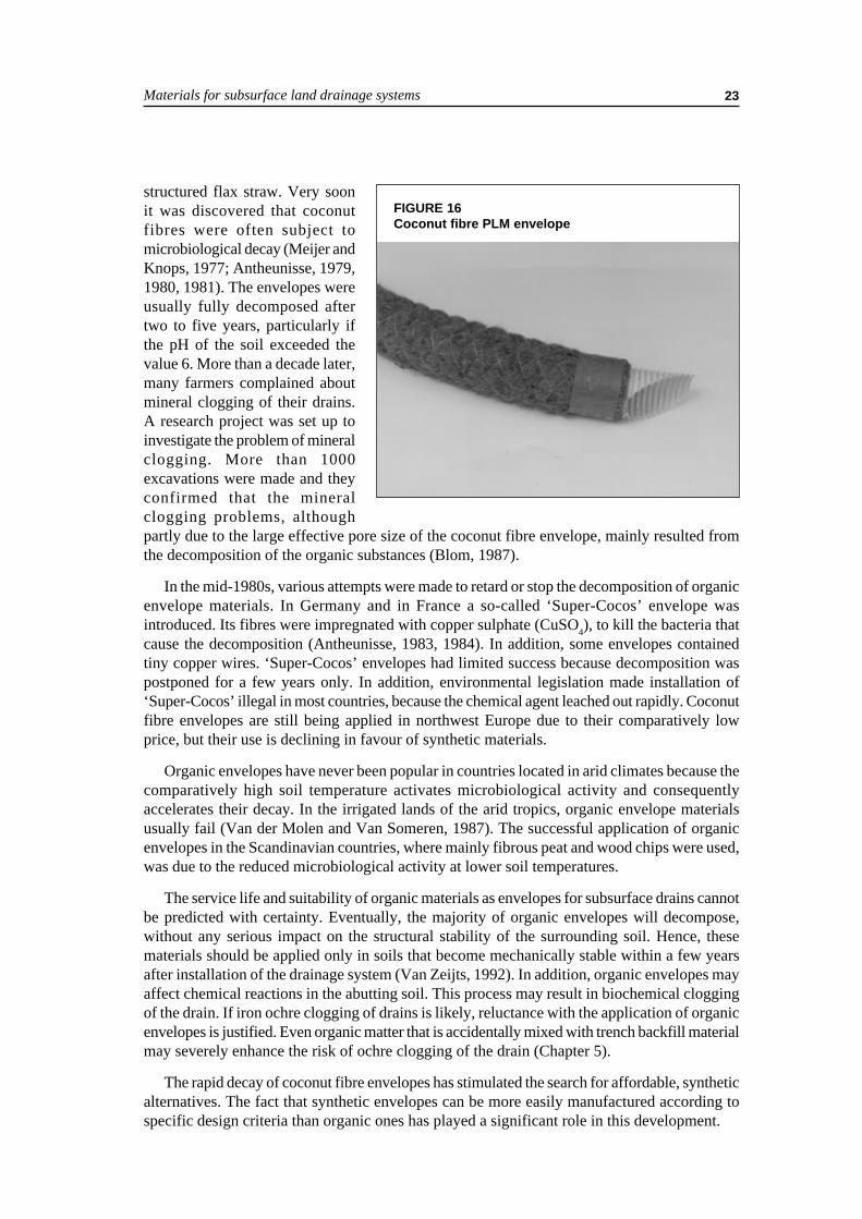
At the end of the 1960s, coconut fibre (Figure 16) was introduced (Jarman and Jayasundera,1975). Being relatively cheap, it soon dominated the market because high quality peat litterbecame scarce and expensive (Meijer, 1973) and because the flax industry declined. Moreover,the finer coconut fibre was considered a more appropriate envelope material than the coarser-
Materials for subsurface land drainage systems 23
structured flax straw. Very soonit was discovered that coconutfibres were often subject tomicrobiological decay (Meijer andKnops, 1977; Antheunisse, 1979,1980, 1981). The envelopes wereusually fully decomposed aftertwo to five years, particularly ifthe pH of the soil exceeded thevalue 6. More than a decade later,many farmers complained aboutmineral clogging of their drains.A research project was set up toinvestigate the problem of mineralclogging. More than 1000excavations were made and theyconfirmed that the mineralclogging problems, althoughpartly due to the large effective pore size of the coconut fibre envelope, mainly resulted fromthe decomposition of the organic substances (Blom, 1987).
In the mid-1980s, various attempts were made to retard or stop the decomposition of organicenvelope materials. In Germany and in France a so-called ‘Super-Cocos’ envelope wasintroduced. Its fibres were impregnated with copper sulphate (CuSO4), to kill the bacteria thatcause the decomposition (Antheunisse, 1983, 1984). In addition, some envelopes containedtiny copper wires. ‘Super-Cocos’ envelopes had limited success because decomposition waspostponed for a few years only. In addition, environmental legislation made installation of‘Super-Cocos’ illegal in most countries, because the chemical agent leached out rapidly. Coconutfibre envelopes are still being applied in northwest Europe due to their comparatively lowprice, but their use is declining in favour of synthetic materials.
Organic envelopes have never been popular in countries located in arid climates because thecomparatively high soil temperature activates microbiological activity and consequentlyaccelerates their decay. In the irrigated lands of the arid tropics, organic envelope materialsusually fail (Van der Molen and Van Someren, 1987). The successful application of organicenvelopes in the Scandinavian countries, where mainly fibrous peat and wood chips were used,was due to the reduced microbiological activity at lower soil temperatures.
The service life and suitability of organic materials as envelopes for subsurface drains cannotbe predicted with certainty. Eventually, the majority of organic envelopes will decompose,without any serious impact on the structural stability of the surrounding soil. Hence, thesematerials should be applied only in soils that become mechanically stable within a few yearsafter installation of the drainage system (Van Zeijts, 1992). In addition, organic envelopes mayaffect chemical reactions in the abutting soil. This process may result in biochemical cloggingof the drain. If iron ochre clogging of drains is likely, reluctance with the application of organicenvelopes is justified. Even organic matter that is accidentally mixed with trench backfill materialmay severely enhance the risk of ochre clogging of the drain (Chapter 5).
The rapid decay of coconut fibre envelopes has stimulated the search for affordable, syntheticalternatives. The fact that synthetic envelopes can be more easily manufactured according tospecific design criteria than organic ones has played a significant role in this development.
FIGURE 16Coconut fibre PLM envelope
Envelope materials24
Synthetic envelopes
Prewrapped loose materials
A synthetic PLM is a permeable structure consisting of loose, randomly oriented yarns, fibres,filaments, grains, granules or beads, surrounding a corrugated drainpipe, and retained in placeby appropriate netting and/or twines. Synthetic PLM envelopes are usually wrapped around thecorrugated plastic drainpipes by specialized companies and occasionally in pipe manufacturingplants. The finished product must be sufficiently strong to resist handling and installation withoutdamage.
Synthetic PLMs include various polymeric materials. Fibres may be made of polyamide(PA), polyester (PETP1), polyethylene (PE), and polypropylene (PP). Loose polystyrene (PS)beads can be wrapped around drains as PLMs in perforated foil or in string netting (‘geogrids’or ‘geonets’). The beads are subject to compression from soil loads that may reduce envelopepermeability (Willardson et al., 1980). In various European countries where the drain depthranges from 0.9 to 1.2 m, the effectof the soil load is howeverrelatively small. PLM envelopesmade from PP (waste) fibres areincreasingly used in northwestEurope and in arid areas wherethey replace expensive gravel.
Information on some envelopematerials, which are shown inFigures 17-20, is given below.Figures concerning the marketshares of various envelopematerials (‘turnover’) are given forThe Netherlands, in 1997, forillustrative purpose only. The dataare based upon the installed lengthsof wrapped drainpipes.
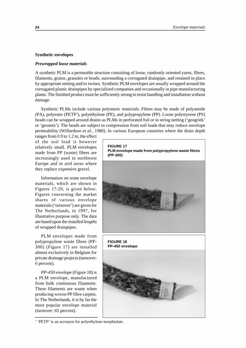
PLM envelopes made frompolypropylene waste fibres (PP-300) (Figure 17) are installedalmost exclusively in Belgium forprivate drainage projects (turnover:6 percent).
PP-450 envelope (Figure 18) isa PLM envelope, manufacturedfrom bulk continuous filaments.These filaments are waste whenproducing woven PP fibre carpets.In The Netherlands, it is by far themost popular envelope material(turnover: 65 percent).
1 ‘PETP’ is an acronym for polyethylene terephtalate.
FIGURE 17PLM envelope made from polypropylene waste fibres(PP-300)
FIGURE 18PP-450 envelope

Materials for subsurface land drainage systems 25
PP-700 envelope is a PLMmaterial, made from new PP fibres(Figure 19). Wrapping of pipes withthis envelope is comparativelylaborious, hence the high price(turnover: 4 percent). It is mainlyused for larger pipe diameters(exceeding 160 mm).
Due to the declining availabilityof PP waste fibres at competitiveprices, waste PA fibres are usedoccasionally. Contrary to PP fibres,PA fibres absorb water as a resultof which the coils may substantiallyincrease in weight. In addition, it ismore difficult to process PA fibresto homogeneous prewrappedenvelopes because of problemswith static electricity.
PS-1000 is a PLM envelopematerial that is manufactured fromcompressible PS beads in netting(Figure 20) and almost exclusivelyinstalled in agricultural areas whereflower bulbs are grown (turnover:7 percent). In these areas, thegroundwater contains a relativelyhigh amount of suspendedparticles, and PS-1000 has provena very reliable envelope. In thisapplication, the higher price of PS-1000 is a good investment; nofarmer can afford to have drainagesystems fail.
Synthetic materials deteriorate when exposed to solar (UV) radiation. Experiments withPLM envelopes, made of PP fibres in a temperate climate have indicated that deterioration canbe hazardous within three years (Dierickx, 1998b). The speed of the deterioration will be doublein semi-arid and arid regions where the average annual radiation is twice that in temperateregions. However, once installed, synthetic PLM envelopes, manufactured from suitable rawmaterial (e.g. recycled PP fibres) are not subject to decomposition. These materials are thereforereliable and affordable substitutes for conventional gravel and organic envelopes.
Prewrapping with loose materials is limited to diameters of 200 mm or smaller. Onceprewrapped around drains, PLM envelopes have functional properties that are similar to thoseof geotextiles.
FIGURE 19PP-700 envelope
FIGURE 20PS-1000 envelope
Envelope materials26
Geotextile envelopes
According to prEN2 30318 (1998), a geotextile is defined as ‘a planar, permeable, polymeric(synthetic or natural) textile material, which may be woven, non-woven or knitted, used incontact with soils and/or other materials in civil engineering for geotechnical applications’.This definition includes application in agriculture since civil engineering incorporates drainageengineering in many countries.
Woven geotextiles are manufactured by interlacing, usually at right angles, two or more setsof yarns, fibres, filaments, tapes, or other elements. Non-woven geotextiles are sheets, webs, orbatts, consisting of directionally or randomly oriented fibres, filaments, or other elements. Theseelements are bonded by mechanical, thermal and/or chemical means. Knitted geotextiles aremanufactured by interlooping one or more yarns, fibres, filaments, or other elements.
The fibres, used for production of geotextiles are made from the same raw materials as thoseused for PLMs, namely: polyamide (PA), polyester (PETP), polyethylene (PE), andpolypropylene (PP). The fibres of geotextiles may be monofilaments, multifilaments or tapes;the latter either flat, fibrillated or twisted. The combination of raw materials, fibre configurationand weaving, bonding or knitting techniques results in many types of geotextiles which differwidely in appearance, physical, mechanical and hydraulic properties.
In principle, geotextiles may be used as envelope material for drainpipes because they possesstwo important properties that are required for a drain envelope, namely water permeability andsoil particle retention. Moreover, they facilitate the water acceptance of drainpipes, and theyconvey water in their plane, alongside the pipe wall. Woven geotextiles, however, are seldomused for the manufacturing of drain envelopes. The only justification for this fact must be theircomparatively high price, becausetheir specifications are indeedfavourable.
In some European countrieswhere organic and synthetic PLMsare used, there is persistentreluctance to use geotextiles asdrain envelope because it is arguedthat their fine texture may enhancemineral and ochre clogging. Yet incountries with a geotextile industrylike France, Canada and the UnitedStates, geotextile envelopes areapplied successfully at a largescale. Laboratory experiments,field trials and practicalexperiences do not give clearevidence of the clogging risk of properly selected and properly installed fine textured geotextiles.There are, however, circumstances where fine textured geotextiles should preferably not beused (see Chapter 5).
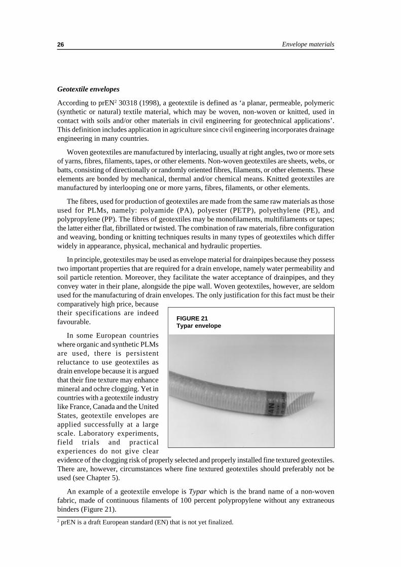
An example of a geotextile envelope is Typar which is the brand name of a non-wovenfabric, made of continuous filaments of 100 percent polypropylene without any extraneousbinders (Figure 21).2 prEN is a draft European standard (EN) that is not yet finalized.
FIGURE 21Typar envelope

Materials for subsurface land drainage systems 27
Wrapping of drains with geotextiles can be done for any diameter. Geotextile strips can betied around the corrugated drain, or pulled over it after the edges have been sewn together.
Geotextiles that are exposed to solar natural weathering are also vulnerable to degradation.Rankilor (1992) recommends that exposure of geotextiles to natural weathering may not lastlonger than two months in temperate regions and only one week in arid and semi-arid regions.Geotextiles, manufactured from organic raw material such as jute will decay in a similar fashionas organic PLMs do, while synthetic geotextiles, like synthetic PLMs, do not.
SPECIFICATIONS FOR DRAIN ENVELOPES
In 1922, Terzaghi developed ‘filter’ criteria to control seepage under a dam. These criteriahave since been tested for applicability for envelopes around subsurface drains. Terzaghirecommended that the ‘filter’ material be many times more pervious than the soil base materialbut that it not be so coarse that the base material would move into the ‘filter’. Terzaghi’sdevelopment has served as a basis for much work done since that time on gravel envelopedesign. For drain envelopes, his design criteria have been tested and modified, but his originalconcepts have been generally accepted.
Van Someren (FAO, 1972) reported on the research into and the guidelines for selectionand application of drainage materials (pipes and envelopes) in various countries. In Belgiumand The Netherlands, efforts were made to develop special design criteria for prewrappedloose materials (PLMs). Conventional design criteria were largely determined by analoguemodels in laboratories, supported by theoretical considerations, and verified by field trials.Monitoring the flow of water and soil particles near prewrapped drainpipes in the field was notan easy task without disturbing the system. In addition, the data, emerging from fieldexperimentation are inevitably blurred because it is site specific. Results achieved at someplaces are not necessarily replicable at other locations.
Knops et al. (1979) published the first set of comprehensive guidelines for the selection ofthe then used prewrapped envelopes for use in Dutch soils. Subsequently, a series of researchprojects and concurrent practical evaluations, carried out by various companies and institutions,have produced design and application criteria for drain envelopes made of PLMs in TheNetherlands (Huinink, 1992; Stuyt, 1992a; Van Zeijts, 1992). Many field surveys have beenmade into the possible factors that affect pipe sedimentation.
Drain envelopes should meet specifications but visual evaluation of materials is alsoimportant. Even if the best materials have been used and all specifications are met, a drainagesystem will not operate properly if envelopes exhibit some shortcomings due to carelesswrapping, handling or installation.
Specifications for gravel envelopes
Specifications for gravel envelopes are discussed extensively in numerous publications. Thissection contains all the major issues. Sound design criteria for traditional granular envelopes(gravel and coarse sand) are available and have been applied successfully in practice (Terzaghiand Peck, 1961; Vlotman et al., in press; Stuyt and Willardson, 1999).
The US Army Corps of Engineers and the US Bureau of Reclamation have made extensivestudies of gravel envelopes. The result is a set of specifications for graded gravel envelopes,which have been successfully used by the Soil Conservation Service (SCS, 1973), the USBureau of Reclamation (USBR, 1993) as well as outside the United States.

Envelope materials28
The gradation curve of a proposed gravel envelope should be matched to the soil to bedrained, as well as to the pipe perforations (Willardson, 1979). In addition, gravel should beinternally stable to avoid internal envelope erosion. The general procedure for designing agravel envelope for a given soil is as follows:
1. make a mechanical particle size analysis of both the soil and the proposed gravel envelope;2. compare the two particle size distribution curves; and3. decide, by some design criterion, whether the proposed gravel envelope material is suitable.
The involved design criteria consist of rules that prescribe how to derive the particle sizedistribution, required for a suitable gravel envelope, from particle size distribution data of thesoil, in order to guarantee satisfactory service of the envelope.
Terzaghi’s criteria
The first criteria, proposed by Terzaghi (US Army Corps of Engineers, 1941) for what hetermed a ‘filter’, are:
• The particle diameter of the 15 percent size of the filter material (D15)3 should be at least
four times as large as the diameter of the 15 percent size of the soil material (d15):
D15 ≥ 4 d15
This requirement would make the filter material roughly more than ten times as permeableas the soil.
• The 15 percent size of the filter material (D15) should not be more than four times as large asthe 85 percent size of the soil material (d85):
D15 ≤ 4 d85
This requirement would prevent the fine soil particles from washing through the filter material.
Bertram (1940), Karpoff (1955), and Juusela (1958) suggested similar or modified ‘filter’design criteria for use with subsurface drains.
Criteria of the US Soil Conservation Service
The SCS (1971) has combined the results of the research on gravel envelopes into a specificationfor evaluating pit run and artificially graded granular materials for use as drain envelope materials.These specifications are superseded by more recently published specifications (SCS, 1988),which distinguished between ‘filter’ and ‘envelope’. The recommendation for naturally gradedmaterials or a mixture of medium and coarse sand with fine and medium gravel for use asenvelope is:
• D100 ≤ 38 mm.• D30 ≥ 250 µm.• D5 ≥ 75 µm.
Additional criteria are suggested to prevent excessive fineness of an envelope material,designed to be used for finer textured soils (SCS, 1988):
3 The particle diameter Dx of the x percent size by weight of the filter material is defined as the diametersieve where x percent passes. This also holds for the soil parameter dx.
Materials for subsurface land drainage systems 29
• D15 < 7 d85 but D15 ≥ 0.6 mm.• D15 > 4 d15.
Criteria of the US Bureau of Reclamation
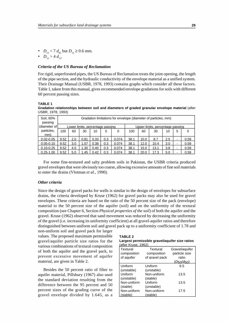
For rigid, unperforated pipes, the US Bureau of Reclamation treats the joint opening, the lengthof the pipe section, and the hydraulic conductivity of the envelope material as a unified system.Their Drainage Manual (USBR, 1978, 1993) contains graphs which consider all these factors.Table 1, taken from this manual, gives recommended envelope gradations for soils with different60 percent passing sizes.
TABLE 1Gradation relationships between soil and diameters of graded granular envelope material (afterUSBR, 1978, 1993)
For some fine-textured and salty problem soils in Pakistan, the USBR criteria producedgravel envelopes that were obviously too coarse, allowing excessive amounts of fine soil materialsto enter the drains (Vlotman et al., 1990).
Other criteria
Since the design of gravel packs for wells is similar to the design of envelopes for subsurfacedrains, the criteria developed by Kruse (1962) for gravel packs may also be used for gravelenvelopes. These criteria are based on the ratio of the 50 percent size of the pack (envelope)material to the 50 percent size of the aquifer (soil) and on the uniformity of the texturalcomposition (see Chapter 6, Section Physical properties of the soil) of both the aquifer and thegravel. Kruse (1962) observed that sand movement was reduced by decreasing the uniformityof the gravel (i.e. increasing its uniformity coefficient) at all gravel-aquifer ratios and thereforedistinguished between uniform soil and gravel pack up to a uniformity coefficient of 1.78 andnon-uniform soil and gravel pack for largervalues. The proposed maximum permissiblegravel/aquifer particle size ratios for thevarious combinations of textural compositionof both the aquifer and the gravel pack, toprevent excessive movement of aquifermaterial, are given in Table 2.
Besides the 50 percent ratio of filter toaquifer material, Pillsbury (1967) also usedthe standard deviation resulting from thedifference between the 95 percent and 50percent sizes of the grading curve of thegravel envelope divided by 1.645, as a
TABLE 2Largest permissible gravel/aquifer size ratios(after Kruse, 1962)Texturalcompositionof aquifer
Texturalcomposition
of gravel pack
Gravel/aquiferparticle size
ratio(D50/d50)
Uniform(unstable)
Uniform(unstable)
9.5
Uniform(unstable)
Non-uniform(stable)
13.5
Non-uniform(stable)
Uniform(unstable)
13.5
Non-uniform(stable)
Non-uniform(stable)
17.5
Gradation limitations for envelope (diameter of particles, mm)
Lower limits, percentage passing Upper limits, percentage passing
Soil, 60%passing
(diameter ofparticles,
mm)100 60 30 10 5 0 100 60 30 10 5 0
0.02-0.05 9.52 2.0 0.81 0.33 0.3 0.074 38.1 10.0 8.7 2.5 - 0.590.05-0.10 9.52 3.0 1.07 0.38 0.3 0.074 38.1 12.0 10.4 3.0 - 0.590.10-0.25 9.52 4.0 1.30 0.40 0.3 0.074 38.1 15.0 13.1 3.8 - 0.590.25-1.00 9.52 5.0 1.45 0.42 0.3 0.074 38.1 20.0 17.3 5.0 - 0.59

Envelope materials30
criterion for its effectiveness. Pillsbury (1967) presented a graph of the 50 percent size ratioenvelope-aquifer vs. this standard deviation which was divided in two zones. Envelopes thatfall below the limit line were judged unsatisfactory. Based on observations of some drainenvelopes that had failed in the Imperial Valley of California, Pillsbury recommended anenvelope-aquifer ratio of less than 24. He concluded that concrete sand, satisfying the appropriateAmerican Society for Testing and Materials (ASTM) standard with a 50 percent size less than1 mm and a standard deviation greater than 1.0 would be a satisfactory envelope material undermost conditions.
Sherard et al. (1984a, b) developed filter criteria for protection of hydraulic structures.While not intended for application in subsurface drainage, the principles may equally well beapplied for the design of gravel envelopes. The authors established that if a filter did not failwith the initial flow of water, it was probably permanently safe. Well-graded materials weremore successful than uniform materials.
Sherard et al. (1984b) reported on tests with fine textured soils and concluded the followingwith respect to filter and base soil sizes:
• Sandy silts and clays (d85 of 0.1 - 0.5 mm) D15/d85 ≤ 5 is safe.• Fine-grained clays (d85 of 0.03 - 0.1 mm) D15 < 0.5 mm is safe.• Fine-grained silts of low cohesion (d85 of 0.03 - 0.1 mm) D15 < 0.3 mm is safe.• Exceptionally fine soils (d85 < 0.02 mm) D15 < 0.2 mm or smaller is safe.
Sands and gravely sands containing fine sand fractions and having a D15 of 0.5 mm or lesswould be a suitable filter for even the finest clays. For clays with some sand content (d85 > 1.0mm), a filter with a D15 = 0.5 mm would satisfy the D15/d85 ≤ 5 criterion. For finer clays, the D15/d85 ≤ 5 is not satisfied, but the finer soils tend to be structurally stable and are not likely to fail.Finally, Sherard et al. (1984b) found that well-graded gravely sand was an excellent filter forvery uniform silt or fine uniform sand, and that it was not necessary that the grading curve ofthe envelope be roughly the same shape as the grading curve of the soil. Gravel envelopes thathave a D15 of 0.3 mm and a D15/d85 ≤ 5 with less than 5 percent of the material finer than 0.074mm will be satisfactory as envelope materials for most problem soils.
Dieleman and Trafford (FAO, 1976) reviewed criteria for selection of gravel envelopematerials and included some comments regarding envelope selection for problematic soils.Dierickx (1992b) presented a summary of gravel envelope criteria from the United States andthe United Kingdom. This summary clearly indicates that the criteria from various sources donot match, even if one takes into account the difference between ‘filter’ (mechanical) functionand ‘envelope’ (hydraulic) function. This fact has prompted new research projects that haveyielded new findings, i.e. improvements of existing criteria, which may be used to improve thedesign gravel envelopes (Vlotman et al., 1997). Another finding of interest was that roundedand angular particles gave equivalent results (Vlotman et al., 1992b).
Specifications for prewrapped envelopes
Prewrapped envelopes may be organic PLM, synthetic PLM and geotextile. Their physicalproperties such as thickness and mass per unit of surface area are important to check theuniformity of the envelopes, and their conformity with the required design standards.Characteristic opening size, hydraulic conductivity and water repellence determine the hydraulic

Materials for subsurface land drainage systems 31
properties of prewrapped envelopes. When using loose granular materials, particle sizedistribution parameters may be used as well. Depending on what kind of drain pipes is used andhow envelope materials are wrapped around drainpipes, some mechanical properties of envelopessuch as compressibility, abrasion damage, tensile strength and static puncture resistance maybe part of the specifications.
In The Netherlands, recommendations for the design and application of PLMs have beendeveloped on the basis of concurrent research projects, theoretical studies, mathematicalmodelling, empirical studies in experimental fields, analogue modelling in laboratories andpractical experience covering a 30-year period (1960-1990) (Stuyt, 1992a).
Thickness
The thickness of prewrapped envelopes serves as a reference for uniformity and conformity. Inaddition, envelope thickness is found a factor of importance in theoretical analyses as it influencesthe soil retention capacity, the entrance resistance of drainpipes and the exit gradient at the soil-envelope interface.
The main task of an envelope is soil particle retention. In this respect, design criteria forenvelope thickness are irrelevant. Thicker envelopes, however, may have higher porosities,which explain their popularity when chemical clogging is anticipated. Therefore, in the envelopeselection procedure, envelope thickness is an important parameter, and often significant interms of safety.
The thickness of an envelope should be a relevant specification if reduction of entranceresistance is envisaged or if reduction of entrance resistance is the only objective to use anenvelope (see Chapter 4, Section Entrance and approach flow resistance). Although a thinenvelope may substantially reduce the entrance resistance, the optimal reduction is obtained ata thickness of 5 mm, provided that the hydraulic conductivity of the geotextile is not the limitingfactor, which will generally not be the case (Nieuwenhuis and Wesseling, 1979; Dierickx, 1980).A further increase of thickness has no marked influence on the entrance resistance, althoughthe effective radius continues to increase since a comparatively permeable envelope replacessoil material that is usually less permeable.
When envelopes are used to reduce the exit gradient (see Chapter 4, Section The exitgradient), the thickness of the envelope is also a relevant design parameter. The design procedurefor envelope thickness, as proposed by Vlotman et al. (in press) shows that even thin geotextiles(≤ 1 mm) may considerably reduce the exit gradient at the soil-envelope interface. The largerthe diameter of a drain, however, the smaller hydraulic gradients near the drain will be. Hence,‘thick’ or ‘voluminous’ envelopes (i.e. thickness > 5 mm) are generally considered to be saferthan thin ones, particularly if the drains are occasionally used for controlled drainage orsubirrigation (subsurface infiltration).
For PLM, the specification of a minimum thickness was introduced to guarantee a completecover with a more or less homogeneous envelope. According to the provisional EN-standard(CEN/TC155/WG18, 1994), the following minimum thicknesses are required:
• Synthetic, fibrous PLMs: 3 mm (e.g. PP fibres).• Synthetic, granular PLMs: 8 mm (e.g. polystyrene beads).• Organic, fibrous PLMs: 4 mm (e.g. coconut fibres).• Organic, granular PLMs: 8 mm (e.g. wood chips, sawdust).

Envelope materials32
The provisional EN-standard further specifies that the mean average thickness of each testpiece should not deviate by more than 25 percent from that declared by the manufacturer.
Geotextiles are available from very thin, sheet-like fabrics to rather thick, mat-like materials.
Mass per unit area
The mass per unit area is not a selection criterion and therefore not specified. Mass determinationcan be carried out as a control measure for uniformity and conformity. According to theprovisional EN-standard, the mass also may not deviate by more than 25 percent of the massspecified by the manufacturer in order to safeguard a homogeneous product.
Characteristic opening size and retention criterion
The characteristic opening size, derived from the pore size distribution or porometric curve ofthe envelope, is the most important selection criterion because it determines the effectivenessof the envelope to retain the surrounding soil material.
The retention of soil particles is normally not a problem since very fine fabrics are available.Laboratory research as well as practical experience, however, have revealed that fine envelopesare vulnerable to mineral blocking and clogging. Blocking of an envelope is a decrease of thenumber of active openings in an envelope that occurs when it is brought in contact with a soil.Clogging, on the other hand, is a decrease with time of the number of active openings in anenvelope due to gradual accumulation of particles inside and on its surface, e.g. by particlessuspended in turbid water. Therefore, specifications for envelopes should cover both soil retentioncriteria and criteria to prevent clogging and blocking of the envelope. Intensive research hasresulted in criteria for soil particle retention and in recommendations with respect to the problemsof blocking and clogging.
The capability of an envelope to retain the soil material is expressed as a ratio of somecharacteristic pore size of an envelope to some characteristic particle size of the soil in contactwith this envelope. In many countries, the O90 is used as the characteristic pore size for organicand synthetic PLMs and geotextiles alike, with a great deal of success.
The O90 of a drain envelope is the pore size for which 90 percent of the envelope pores aresmaller. The O90 value is usually obtained by dry sieving of well-known sand fractions, wherebythe envelope itself is installed as a sieve and the retained amount of each fraction is recorded.Wet and hydrodynamic sieving, also applied for this purpose, use graded soil and mostly resultin smaller O90 values than those obtained with dry sieving.
In 1994, a working group of scientists and engineers in Europe developed a new classificationsystem for PLMs. They introduced three classes of envelopes, depending on the effective openingsize of the envelope pores, O90, as follows:
PLM-XF extra fine 100 µm ≤ O90 ≤ 300 µm.PLM-F fine 300 µm ≤ O90 ≤ 600 µm.PLM-S standard 600 µm ≤ O90 ≤ 1100 µm.
In the provisional EN-standard (CEN/TC155/WG18, 1994) only two classes, namely PLM-F and PLM-S have been accepted.
In The Netherlands, practical guidelines for envelope application consider three ‘standard’O90 values, namely 450, 700 and 1000 µm, 450 µm being by far the most widely applied, and

Materials for subsurface land drainage systems 33
servicing a great variety of soils. These figures were accepted after Stuyt (1992a), using fielddata, confirmed evidence of the soundness of the O90 parameter. In Belgium, the O90 of a PLMenvelope should range between 600 and 1000 µm for official drainage works.
A frequently used retention criterion, also called filter criterion or bridging factor of anenvelope, is the ratio O90/d90. In this ratio, d90 is the particle diameter of the soil in contact withthe envelope where 90 percent of the particles, by weight, is smaller. Numerous other retentioncriteria have been proposed in the scientific literature, which have been published incomprehensive tables, by e.g. Dierickx (1993) and Vlotman et al. (in press). For the designengineer, however, the number of criteria is confusing, the more so because many criteria arecontradictory. This fact is self-explanatory, because the criteria were developed under widelydifferent boundary conditions, using many different techniques, equipment and so forth.
Laboratory experiments have unambiguously indicated that the likelihood of soil particleretention is greater when a fabric is thicker. Hence, the characteristic pore size of an envelopemay be larger for thicker envelopes, for equal retention. Indeed, retention criteria are linked toenvelope thickness.
From laboratory studies with analogue soil models, Dierickx (1987), and Dierickx and Vander Sluys (1990) derived the following simple retention criteria for subsurface drainageapplications:
• O90/d90 ≤ 5 for ‘thick’ envelopes ≥ 5 mm (PLMs).• O90/d90 ≤ 2.5 for ‘thin’ envelopes ≤ 1 mm (geotextiles).
For envelopes with a thickness ranging between 1 and 5 mm, the O90/d90 ratio may beinterpolated step-wise (Dierickx, 1992a) or linearly (Vlotman et al., in press). The step-wiseapproach gives one value of O90/d90 for a range of thicknesses and is somewhat more practicalthan a linear approach which yields a specific value of O90/d90 for each thickness.
Retention criteria for thicknesses of PLMs and geotextiles between 1 and 5 mm, accordingto the step-wise approach are:
• O90/d90 ≤ 3 for thicknesses between 1 and 3 mm.• O90/d90 ≤ 4 for thicknesses between 3 and 5 mm.
Taking into account the retention criterion of a thin envelope, most problems in subsurfacedrainage will be prevented by envelopes for which O90 ≥ 200 µm.
Field observations of Stuyt (1992a,b) confirmed, in a large extent, the laboratory findings.Stuyt investigated the relation between the O90 size of envelope materials and the thickness ofthe sediment layer inside the pipes using a miniature video camera five years after theirinstallation. In total, 9634 m of drains were investigated (184 laterals). The pipes had outerdiameters of 60 and 65 mm. In The Netherlands, sediment layers exceeding 15 mm are generallynot tolerated. The d90 size of the soils was approximately 150 µm in most cases. The correlationbetween the thickness of the sediment layer inside the pipes and the O90 size of envelope wassignificant (Table 3). Regardless of the O90 size, voluminous envelopes retained more soil thanthin envelopes. Envelopes with larger O90 values, i.e. having larger openings, had poorer soilretention properties. The raw material from which the envelopes were manufactured was notsignificant. Stuyt (1992a) also found that the above-proposed O90/d90 ratios were valid for theinvestigated problem soils. Most of the applied envelopes in the experimental fields had ratherhigh O90/d90 ratios (4 to 5).

Envelope materials34
TABLE 3Fitted values for pipe sedimentation depth (mm) from a regression model, depending on effectiveopening size of the envelope pores, O90, and envelope category (thin or voluminous) forobservations made at three experimental fields in The Netherlands (after Stuyt, 1992a)
Experiments with turbid water or water charged with soil suspensions indicate that geotextilesare vulnerable to clogging when O90/d90 ≤ 1 (Dierickx, 1990; Faure, 1991). Hence, the ratioO90/d90 = 1 is the lower limit for soil particle retention, regardless of envelope thickness. Thephenomena of blocking and clogging of an envelope are however not so evident, neither inlaboratory experiments with soils, nor in field experiments. Therefore, the lower limit O90/d90≥ 1 should be considered a recommendation rather than a rigid design criterion.
In the investigation made by Stuyt (1992a), envelopes with O90/d90 near 1 had such lowsedimentation depths that the envelopes appeared to act as filters. Hence, for thin geotextiles,the O90/d90 ratio should preferably be near the upper limit. On the other hand, the upper limit, setto 5 for voluminous envelopes (Dierickx, 1987) appears safe for voluminous PLMs since amaximum sedimentation depth of 15 mm is tolerated in 60 and 65 mm outer diameter pipes(Table 3). In soils with some cohesion and, hence, some structural stability, voluminous envelopeswith O90/d90 ratios as high as 7 have been applied successfully.
In The Netherlands and in Belgium, the successfully applied retention criterion O90/d90 forenvelopes was therefore adopted as the major design parameter. Recommendations for envelopeapplications are also based on some additional considerations (Huinink, 1992; Van Zeijts, 1992)but the O90/d90 criterion is the most important one.
Locally made fabrics such as carpet backing, which satisfies or may satisfy the aboverequirements after some modifications, are equally suitable as imported geotextiles. They maytherefore be trusted as envelope materials.
Hydraulic conductivity
The hydraulic conductivity of envelopes should be greater than that of the soil in order toreduce the entrance resistance of drainpipes, so that no hydraulic pressure will develop outside
Experimental fieldUithuizermeeden Valtermond WillemstadO90
(µm) Thin Voluminous Thin Voluminous Thin Voluminous250 2.1 0.9 4.5 0.8 9.7 8.5500 3.9 2.6 6.3 2.5 11. 10.21000 5.6 4.3 8.0 4.3 13.2 11.9
In summary, the following retention criteria for both geotextiles and PLMs can be accepted:
1 ≤ O90/d90 ≤ 2.5 for envelope thickness ≤ 1 mm.1 ≤ O90/d90 ≤ 3.0 for envelope thickness between 1 and 3 mm.1 ≤ O90/d90 ≤ 4.0 for envelope thickness between 3 and 5 mm.1 ≤ O90/d90 ≤ 5.0 for envelope thickness ≥ 5 mm.O90 ≥ 200 µm.
In order to minimize the risk of mineral clogging it is recommended that O90/d90 ≥ 1;furthermore, envelopes that have O90/d90 ratios near the upper limit of the proposed rangeof values are generally preferred.
Materials for subsurface land drainage systems 35
the envelope. From research work of Nieuwenhuis and Wesseling (1979) and Dierickx (1980)it may be concluded that a substantial reduction in entrance resistance is obtained when Ke/Ks ≥ 10, where Ke is the hydraulic conductivity of the envelope and Ks that of the soil (seeChapter 4, Section Drain with envelope).
The hydraulic conductivity, perpendicularly to or in the plane of envelope, can hardly be aproblem because envelopes are much more permeable than the adjacent soil that they have toretain. Even under load, the hydraulic conductivity of compressible envelopes will meet theconductivity requirements.
If, however, envelopes are brought in contact with soil, soil particles may fill pores andpartly block their openings as a result of which the hydraulic conductivity at the soil-envelopeinterface will decrease. In addition, envelopes may clog as a result of particle deposits and/orchemical precipitates, and become less permeable with time. Evaluation of blocking and cloggingof envelopes is very difficult. If the lower limit of the retention criteria is taken into account, itmay nevertheless be assumed that a favourable hydraulic conductivity ratio is guaranteed.
Water repellence
PLMs do not exhibit wetting problems, yet geotextiles may do and water repellence may be aproblem. Water repellence means that a minimum water head is required on top of the geotextile,before water starts to flow through it (Lennoz-Gratin, 1992). Once the water has entered thepipe through the envelope, the repellence problem is solved and will generally not return.Wettability resistance also decreases when the geotextile is brought into contact with a moistsoil. Research work carried out by Dierickx (1996a) showed that the wetting problem is mainlyan initial problem of dry geotextiles. The initially required head for the majority of the testedgeotextiles is smaller than 2 mm. For others, it ranges from 5 to 30 mm; one geotextile requiredan initial head of 64 mm. Although initial water repellence of envelopes does not seem to bewidespread, geotextiles that exhibit this phenomenon should not be used as drain envelope toavoid the risk of soil structure deterioration near the envelope due to the initial stagnation ofwater.
In accordance with the standard on the determination of resistance to water penetration oftextile fabrics ISO 811 (1981), a testing procedure has been adopted in the countries of theEuropean Union, to examine geotextiles on water repellence in a qualitative manner (prEN13562, 1999).
Mechanical properties
Mechanical properties of envelopes are mostly of secondary importance. Geotextiles used asdrain envelope do not present specific problems since they are designed for, and are normallyused in more challenging circumstances. Moreover, problems that develop occasionally becauseof handling (e.g. tearing) can be repaired before installation.
The compressibility of compressible envelopes has a major effect on the characteristic openingsize and the hydraulic conductivity. The opening size normally decreases in compressed stateso that a safety factor is built in automatically. The hydraulic conductivity decreases also, yetthe highly permeable nature of the envelope ensures that the hydraulic conductivity ratio is metin compressed state. Moreover, the compressibility of coarser envelopes, composed of coarserfibres, is small. Easily compressible thick envelopes, made of fine fibres should not be used asdrain envelope.
Envelope materials36
Abrasion is the wearing of a part of the envelope by rubbing against another material, eitherduring transportation or installation of wrapped drainpipes. Open spots due to abrasion orwhatever other cause, noticed before installation, should be repaired in the field, if they are notout of proportion. Abrasion during installation is less likely to occur because of the short timethat the wrapped pipe is routed through the machine.
Geotextiles are wrapped around drainpipes either manually or mechanically; therefore, acertain tensile strength is required. Dierickx (1994) proposed a tensile strength of 6 kN/m,determined according to the wide-width tensile test (EN ISO 10319, 1996). Geotextiles mustbridge the corrugations of large drainpipes and may not sag between the corrugations under thesoil load. Hence, elongation should be limited, but this requirement is only meaningful if thegeotextile is tightly wrapped. Since this has never been a practical problem, elongationrequirements have never been put forward.
Resistance to static puncture also is only applicable for drains with large corrugations wherea tightly wrapped geotextile bridges the corrugations. The geotextile should withstand the soilload between the corrugations, and puncturing by stones and hard soil clods. These phenomenaare simulated by a static puncture test. Through this test, the force required to push a flatplunger through a geotextile can be determined. Since such a problem has never occurred insubsurface drainage so far, no requirements exist.
AVAILABILITY AND COST
Cost and availability of drainage materials are strongly interrelated. Costs vary continuouslysince these are dependent on various, partly unpredictable factors like currency exchange ratesand the cost of manual labour. For reference, various indications of the cost of drainage materialsare given in this Chapter.
The cost of gravel envelopes is not specified here because the local availability of suitablegranular material is rapidly declining. In addition, the cost of installation is strongly dependenton local circumstances. In the Integrated Soil and Water Improvement Project (ISAWIP) inEgypt, local gravel envelopes were four times as expensive as imported Canadian syntheticfabric envelopes (Metzger et al., 1992). In the Fourth Drainage Project of the InternationalWaterlogging and Salinity Research Institute (IWASRI) of Pakistan, the cost of syntheticenvelopes was found to be 40 percent lower than that of gravel envelopes. Installation of syntheticenvelopes was easier and faster, too (IWASRI, 1997). Thus, even if the price of gravel iscompetitive, it goes hand in hand with high costs of fuel and manual labour. It is thereforeirrelevant to consider the price of the raw material only. Vlotman et al. (in press) quote costs ofgravel envelopes (material and transport) in various projects in Pakistan. For all projects, thecosts of material and shipping of synthetic materials was below the cost of gravel. Unfortunately,the high cost of gravel installation compared to that of installing prewrapped pipes is not includedin this analysis. The cost/benefit ratio is certainly in favour of PLM envelopes and geotextiles.
PLM envelopes, manufactured from PP fibres and coconut fibres dominate the market innorthwestern Europe. PLM envelopes, manufactured from peat fibres are now used onlyoccasionally.
An indication of the cost of drainage materials, i.e. pipes and PLM envelopes, in TheNetherlands is given in Table 4. Absolute prices are not given. Instead, the relative cost of pipeand envelope material is specified for various pipe diameters and envelope materials. The figures

Materials for subsurface land drainage systems 37
are based upon corrugated PVC pipe, and are quoted for contractors with high rates of turnover.The price of installation of one metre of wrapped drainpipe more or less equals that of onemetre of unwrapped 60 mm pipe.
From Table 4, it can be seen that the price of even the cheapest PLM envelope comprises asubstantial part of the price of a pre-wrapped pipe. This is particularly true for smaller diameterpipes. In 1998, there was a slight upward tendency of the price of polypropylene waste fibres inThe Netherlands. These fibres are no longer available in such huge quantities as they used to bein the past. Dutch pipe wrapping companies are experimenting with other synthetic wastematerials in an effort to be able to market competitive envelopes in the years to come.
TABLE 4The relative cost of PLM envelopes, expressed as a percentage of the cost of the envelope plus acorrugated PVC pipe together as a prewrapped product, in The Netherlands in 1998. The cost ofinstallation is not included. The O90 size is specified within brackets
The selection of an envelope material is determined by various factors. The price is obviouslyimportant. The ease of handling of the material is also a factor of consideration. Coconut fibreenvelopes will release substantial amounts of dust particles during handling and installation,particularly in dry weather; PP fibre wrapping does not. Previous favourable experiences offarmers are important: they tend to ask for a similar envelope when ordering again.
REVIEW OF LOCAL EXPERIENCE ON DRAINAGE MATERIALS
Adequate characterization of soil properties, field conditions (e.g. groundwater table depth)and physical properties of envelope materials is essential. In this context, the term ‘problemsoils’ is rather vague and calls for further definition. This also holds for envelope materials: ageneric description like ‘PP envelope’ is meaningless since it may cover the whole range fromthin geotextiles to voluminous PLMs.
In an envelope selection process, a systematic comparison with experience gained elsewhereis generally very useful. Synthetic envelopes, either PLMs or geotextiles, have proven to bereliable and are successfully applied in Europe, the United States, and Canada for the last 20years. These materials have also been used satisfactorily in large-scale field experiments inEgypt and Pakistan. In the latter country, they have also been used as envelope for interceptordrains. This proves the transferability of synthetic materials from one region to another.
In Framji et al. (1987), the use of envelope materials is summarized for a great number ofcountries. These data are included in the Table 5, which is supplemented with additional
Relative cost of various envelope materialsPipe
diameter(mm)
Coillength
(m)
Typar
(270)
Coconutfibres
(1000)
Polypro-pylenewastefibres
(300)
Polypro-pylenewastefibres
(450)
Poly-ester
knittedsock
(400)
Coconutfibres
(700)
Poly-styrenebeads
innetting
(1000)
Polypro-pylenefibres
(700)
Polypro-pylenefibres
(heavy)
(700)50 200 43 46 47 49 50 54 - 60 7560 150 40 50 44 46 46 50 71* 57 7365 150 35 39 39 41 41 46 62 52 6980 100 33 37 39 41 41 43 - 49 65
100 100 31 40 40 42 37 43 - 47 64* The external diameter of the wrapped 60-mm pipe is 100 mm, i.e. the thickness of the envelope is 20 mm.

Envelope materials38
TABLE 5Drainage materials used in a number of countries
Material Pipes Mineralenvelopes
Organic envelopes Syntheticenvelopes
Clay
Concrete
Plastic
Sand
and
gravel
Slag
Glass
fibre
cloth
Chaff
Sticks
Coconut
fibres
Sawdust
Straw
Rice
straw
Cedar
leaf
Bamboo
Palm
fibres
Peat
fibres
Knitted
sock
Geotextiles
Synthetic
waste
fibres
AustraliaBelgiumCanadaChinaColombiaCosta RicaCubaCzech Rep.DenmarkEgyptEthiopiaGermanyFranceHungaryIndiaIranIraqIsraelIrelandJapanJordanNetherlandsPakistanPeruPolandPortugalRomaniaSouth AfricaSpainThailandTurkeyUgandaUSAZambiaZimbabwe

Materials for subsurface land drainage systems 39
information from other sources, included that provided by the participants of the InternationalCourse on Land Drainage (Wageningen, 1997-1999). Some local experiences that are consideredto be informative are briefly discussed below.
Arid and semi-arid zones
In the Melka Sadi Pilot drainage scheme in Ethiopia, trials were conducted for evaluatingdrainage envelopes. Three different envelopes were tested in a pilot scheme, comprising locallyavailable red ash, gravel and a factory made fabric filter. The cost of gravel was six times thatof fabric filter. The performance of both gravel and red ash were superior to that of the fabricfilter (Woudeneh, 1987).
In Egypt, voluminous envelope materials that are produced locally, namely PP and PAwaste fibres (O90 of 330 and 400 µm, respectively) performed satisfactorily (Dierickx, 1992a).Occasionally, however, the wrapping of drainpipes proves to be poor. The yarn of prewrappedpipes was slack and the envelope material did not fully cover the pipe. After shipping andhandling in the field, bare spots emerged at many places. In addition, taping of the envelope ateither end of coils was sometimes inadequate as a result of which the envelope was loose (DRI,1997).
In the north-western irrigation districts of Mexico, locally produced corrugated PE pipesare used, with a diameter of 100 mm for laterals and 150 mm for collectors. They must complywith ASTM standards (Chapter 9). Collector pipes are approximately twice as expensive aslaterals. Polyester sock is used as drain envelope, the cost of which is 30 percent of the price ofthe wrapped pipe.
An encouraging result of recent envelope testing projects in Pakistan is that syntheticmaterials, produced in Pakistan, performed well in the laboratory and have shown their potentialfor field application. It is not unlikely that IWASRI will eventually recommend the PakistanWater and Power Development Authority (WAPDA) to replace gravel envelopes with locallymanufactured synthetic materials. Locally manufactured materials were found to outperformfiner local and imported materials, and hence are subjected to additional field trials. In theMardan Scarp salinity control and reclamation project in Pakistan, Dierickx et al. (1995)recommend envelopes with an O90 ranging from 200 to 400 µm.
In Peru, gravel and coarse sand are available everywhere at very reasonable cost, and havebeen successfully installed by hand and trenching machines. The use of clay and concrete tileshas not been very successful. Many soils are very unstable, and accurate installation of drainswas complicated. Installation by hand was quite slow, and the width of excavation at the soilsurface was 6 to 15 times that of the trench box of a trenching machine. Concrete pipes wereexpensive, because they had to be made from sulphate resistant cement. Most Peruvian soilsthat are suitable for agriculture have a very high content of calcium sulphate. Furthermore, therate of production of concrete pipes was quite low. Between 1983 and 1985, 400 km of 65 mmand 100 mm corrugated pipe was installed. These pipes were manufactured in Peru with anextruder, imported from Europe (De la Torre, 1987).
Humid Tropics
In Costa Rica, corrugated pipes were imported from the United States to drain fruit plantations,mainly bananas, notably in medium to coarse sands. In finer soils with low structural stability,the pipes were mostly prewrapped with geotextiles, e.g. spun bonded polyamide (Murillo, 1987).

Envelope materials40
In India, drainage materials are produced locally. Agricultural drainage systems are solelyinstalled on an experimental basis. In heavy clay soils, drains are installed without envelopematerial, and the systems perform satisfactorily. Locally made geotextiles are used with success;problems are rarely encountered (Oosterbaan, 1998). In the mid-1980s, the functioning ofsubsurface drainage systems was investigated in pilot areas, using clay tiles, installed in manuallyexcavated trenches (Singh, 1987). In 1998, the majority of the drainage systems is still beinginstalled by manual labour.
Temperate zones
In Belgium, the use of clay tiles was discontinued in 1975 when their application was supersededby corrugated PVC pipes. Since a potential risk of mineral clogging exists in nearly all soils,envelopes are used everywhere. Envelope materials have evolved from flax straw and coconutfibres to loose synthetic fibres. Currently, loose synthetic PP fibre wrapping is almost exclusivelyused, but coconut fibre wrapping is still available.
In the Scandinavian countries, sawdust from conifer trees is very often used as an envelopematerial for agricultural subsurface drainage systems. In unstable soils in Denmark the pipedrain is protected against mineral clogging by a synthetic sheet beneath the pipe, and gravel orsawdust aside and on top of the pipe. In Norway, 50 percent of the sawdust has usually decayedafter 20 years. Still, some drains have a service life of over 30 years, which will be due to thelow temperatures in Scandinavia. The sawdust is applied in a 50 to 70 mm thick layer (Mortensen,1987).
Approximately 60 percent of the installed drainpipes in the then West-Germany wereprewrapped (Eggelsmann, 1982). Organic envelopes like peat, rye straw and coconut fibrewrappings have been extensively used. Even envelopes made from tannin-containing woodchips to prevent or reduce ochre formation have been developed (Eggelsmann, 1978). Variouskinds of synthetic fibre and granule wrappings have been applied, yet geotextile and loose PPfibre wrappings are the most widely used materials.
Only 5 percent of the drainpipes installed in France need an envelope material. Envelopeshave evolved simultaneously with drainpipes and drainage mechanization. Originally, coconutfibre wrappings have been widely used. The risk of microbiological decay of the coconut fibrewrapping has prompted the introduction of loose synthetic fibre wrappings and, at a later stage,geotextiles. Currently, geotextiles are used almost exclusively (Lennoz-Gratin, 1987).
In The Netherlands, the recommendations for the selection of PLMs are as follows (Huinink,1992; Van Zeijts, 1992):
• Envelopes containing peat fibres and ‘PP-450’ should not be used in case of possible ironochre hazard and/or if the drains are also used for subsurface irrigation purposes during thesummer season.
• Mature or ‘ripened’ clay soils with a clay content greater than 25 percent do not requireenvelopes.
• For most other soils, such as immature clay soils with a clay content greater than 25 percent,(loamy) sand, (sandy) loam, silt loam and peat soils, any envelope may be selected followingthe recommendations, specified in Table 6.
• Exceptions are made for clay soils with a clay content below 25 percent, silts and very finesands which should be drained with ‘PP-450’ or, in case of iron ochre, with ‘PP-700’ only.

Materials for subsurface land drainage systems 41
TABLE 6Applicability of the most popular prewrapped drain envelopes in The Netherlands (adapted fromHuinink, 1992)
In The Netherlands, ‘thin’ envelope materials are used with great caution only, and only inhighly unstable very fine sandy soils (median soil particle diameter < 120 µm). For a variety ofreasons, this category of envelopes has never become very popular. The price of thin envelopesis not competitive, and most farmers simply prefer envelopes to have a ‘visible and substantialthickness’ because they are convinced that such envelopes provide better service than thinones. Reliable data, retrieved from pilot area research projects that convincingly prove that this‘traditional’ viewpoint is not always justified, have not had an appreciable effect. Tradition isindeed a strong factor when it comes to selecting drainage materials, particularly envelopes.
In the Marismas area, located in the Guadalquivir estuary in southern Spain, clay pipes aremainly used although corrugated plastic pipes are installed as well. The clay pipes have aninside diameter of 80 mm, yet a square outside circumference with a small longitudinal hole ineach corner, which is introduced to assure thorough heating of the clay during the manufacturingprocess. The corrugated PVC drains have a diameter of 50 mm. The cost difference betweenclay and PVC drains is small, and farmers, therefore, prefer the larger diameter clay pipes(Martínez Beltrán, 1987). Drains are installed during the dry season when the groundwatertable is below drain level. Drains do not require envelopes because the Marismas soils are verystable due to their clay content greater than 65 percent. Mineral clogging of drainpipes hasnever been observed except for drains whose outlets into open collectors were submergedduring periods of heavy rainfall.
In silty loams and loamy clay soils of the Ebro basin in north-eastern Spain, corrugatedPVC drains with coconut fibre wrapping have been installed in the seventies. There is noinformation on the performance of these drainage materials. Corrugated PVC drains and syntheticfibre wrapping have been used in the sandy soils of the Ebro delta as well.
Envelope material Soil type1
Soils with claycontent > 25% down
to drain depth
Soils with claycontent <25%,loams and very
fine-textured soils,structurally
unstable sands(median particle
diameter < 120 µm)
Loamysandsandeolic
deposits
Sandy soils(medianparticle
diameter >120 µm)
Peatysoils and
peatswith
clayeytopsoils
Soil profile matured to drain depth?Yes No Yes No
‘voluminous’ envelopes(i.e. thickness ≥ 1mm)
Cocos (O90 = 700 or 1000 µm) None2 Yes Yes Yes YesPeat/cocos mix, peat fibres None2 Yes3 Yes3 Yes3 Yes3
Polypropylene fibres 450 µm None2 Yes3 Yes3 Yes3 Yes3 Yes3 Yes3
Polypropylene fibres 700 µm None2 Yes --4 --4 Yes Yes YesPolystyrene beads None2 Yes Yes Yes Yes
‘thin’ envelopes(i.e. thickness < 1mm)
Glass fibre sheet, Cerex, Typar,knitted sock envelope
None2 Yes3,5 Yes3,5
1 In layered soil profiles, envelope selection should be based on the layer with the lowest clay content.2 No envelope required; soil is structurally stable and the risk of mineral clogging of the drainpipe is small.3 Do not install this envelope material if there is a risk of iron ochre clogging, or if the drains are used for
controlled drainage or for subirrigation purposes.4 Use this envelope material only if there is a serious threat of iron ochre clogging the drains.5 Do not use a thin envelope if the soil profile to drain depth contains peaty layers.

Envelope materials42

Materials for subsurface land drainage systems 43
Chapter 4Water flow into and inside the drain
FLOW TOWARDS THE DRAIN
According to Ernst (1954), the flow towards a subsurface drain can be described by a verticalflow (from the groundwater level downward to drain level), a horizontal flow towards thevicinity of the drain, a radial flow to the drain and an entry into it. Each of these flows is subjectto a corresponding resistance (Figure 22a). For steady-state flow, the total resistance can thusbe roughly classified into vertical, horizontal, radial, and entrance resistances. These resistancescan be measured by strategically located piezometers (Figure 22b). Piezometers consist ofunperforated narrow pipes with a short filter at the bottom end in which the water level representsthe hydraulic head in the soil near the filter end. Differences in heads are a measure of theresistances mentioned. The total loss of head, ht, is the sum of all differences indicated inFigure 22b:
• The vertical head loss, hv, is the difference in water level between piezometers 1 and 2,located midway between two drains, with filters at respectively groundwater level and draindepth.
• The horizontal head loss, hh, due to (mainly) horizontal flow towards the drain, is thedifference in water level between piezometers 2 and 3, with filters at drain level respectivelymidway between two drains and in the vicinity of the drain.
FIGURE 22Flow resistances towards a drain flowing at full capacity (a) and their corresponding headlosses (b)

Water flow into and inside the drain44
• The radial head loss, hr, is the difference in water level between piezometers 3 and 4, withfilters at drain level respectively some distance away from the drain and at the drain.
• The entrance head loss, he, is the difference in water level between piezometer 4 and anopen standpipe in the drain.
The relationship between head loss and corresponding resistance is given by:
h* = q L W* (1)
where h = difference in head (m);L = drain spacing (m);q = specific discharge (m/d);W = resistance (d/m); and* = subscript v (vertical), h (horizontal), r (radial), e (entry) or t (total).
Thus the total head loss is:
ht = hv + hh + hr + he (2)
Sometimes the resistances W are replaced by the dimensionless quantities α which areindependent of the hydraulic conductivity of the soil:
α* = K*W* or W* = α* / K* (3)
where K = hydraulic conductivity (m/d); andα = geometrical factor (dimensionless).
Hence, the total head is given by:
ht = q L (Wv + Wh + Wr + We ) = q L (αv / Kv + αh / Kh + αr /Kr + αe / Ke ) (4)
This and other drainage theories are used for calculating drain spacings. They are based ona set of assumptions concerning the drain and the physical properties of the soils involved.Although these assumptions are approximate, the outcome is usually sufficient for practicalapplications. One of these assumption is that of an ‘ideal drain’, without entrance resistance,whereby the drain is considered as an equipotential. Generally, it is assumed that the drainsurround (envelope material and loosened soil in the trench) has such a high hydraulicconductivity compared to the undisturbed soil, that the entrance resistance may be neglected.Practical experience has shown that this cannot always be taken for granted. There is still needfor a query, both theoretically and empirically, in which cases substantial entrance resistancesmay be encountered.
Ponding and excess soil water during heavy rains, in spite of the presence of a drainagesystem, may also result from a low permeability layer near the soil surface that causes a suspendedor perched water table. Another cause may be compaction due to heavy machinery, to slakingduring heavy rains and, on sports fields, to playing actions. This low permeability layer simplyprevents the water from reaching the groundwater table, but has nothing to do with the subsurfacedrainage system itself.
Procedures and programs for the design of subsurface drainage systems are in preparationby FAO. Therefore, this analysis will be limited to the influence of the entrance resistance andpipe flow on drain performance.

Materials for subsurface land drainage systems 45
ENTRANCE AND APPROACH FLOW RESISTANCE
Water enters a real drain through a finite number of perforations, which represent at most only1 to 2 percent of the total wall area. Although a real drain does not alter the general radial flowpattern, the streamlines converge to the inlet perforations in the immediate vicinity of the drain.This causes an entrance resistance, We, leading to a head loss on entry, he.
According to Eq. (1) and taking into account Eq. (3) the relationship between entrance headloss and entrance resistance is given by:
ee
ee KLqWLqh α== (5)
The entrance resistance of a real drain can be calculated theoretically for some simpleperforation shapes and patterns, or can be obtained if the flow pattern towards both the idealand real drain can be accurately modelled (Section Entrance resistance of drainpipes). In mostcases, the entrance resistance is obtained empirically from the entrance head loss. Theoretically,the entrance head loss can be obtained directly from piezometer readings outside and inside thedrain (Figure 22b). Practically, however, piezometer 4 will be placed at some short distanceaway from the drain to avoid the disturbance of the soil caused by installing the drain (Figure23) and therefore, the measured head loss involves not only the entrance head loss, but also partof the radial resistance.
As compared to flow to an imaginary, ideal drain, the convergence of streamlines to theinlet perforations of a real drain invokes an additional flow resistance and head loss. Theadditional flow resistance is called entrance resistance and the corresponding head loss isthe entrance head loss.
FIGURE 23Approach flow and total head loss to evaluate drainage performance in experimental fields

Water flow into and inside the drain46
Entrance resistance, resistance of the disturbed soil and the radial resistance are theoreticalconcepts, which cannot be physically separated, nor separately measured in the field.The measured head loss is the ‘lump sum’ of all the head losses which may be theoreticallyconsidered in the approach flow region.
Cavelaars (1967) introduced the concept of ‘approach flow resistance’ (Wap) and ‘approachflow head loss’ (hap) for the flow in the approach region (Figure 23). Similar to Eq. (5), therelationship between both quantities for approach flow can be written as:
apap
apap KLqWLqh α== (6)
The measured head, hap, results from entrance resistance, resistance of the disturbed soilsurrounding the drain, and the radial resistance in the undisturbed soil as shown in Figure 24 fora drain installed in a trench. This also holds for trenchless drainpipe installation, but the disturbedzone will not be so clearly bounded compared to that created by a trencher.
FIGURE 24Drain with or without envelope, disturbed trench backfill and undisturbed soil constitutethe approach flow region
The head loss determined in experimental fields is the approach flow head loss, though it isusually called ‘entrance head loss’, and is used to calculate the ‘entrance resistance’, e.g. byDieleman and Trafford (FAO, 1976).
Materials for subsurface land drainage systems 47
The entrance resistance as defined by Dieleman and Trafford (FAO, 1976) is in fact anapproach flow resistance and differs fundamentally from the theoretical concept of entranceresistance.
It can also be useful to express the approach flow head loss as a percentage of the total headloss. To determine the total head loss, either a piezometer (piezometer 1) as in Figure 22b or awell tube as in Figure 23 can be installed midway between drains. Unlike the piezometer,which is perforated at the bottom over a limited length only, the well tube is perforated overalmost its entire length.
The flow pattern near the drain is very complex due to the disturbed soil where physicalcharacteristics are heterogeneous and change with time and are therefore difficult to predict.The approach flow head loss, hap, is affected by the physical properties of this disturbed soilwhich surrounds the drain (Kap), the drain spacing and the drainage materials used. A goodenvelope material, however, can reduce αap to such low values that the drain will act as almostan ideal drain.
The same holds if the soil around the drain is highly permeable, say Kap = 10 m/d. This ismostly the case in backfilled trenches in clayey soils or after trenchless drainage in well-structuredclays and clay-loams. Thus, entrance resistance is seldom a problem in these soils, even in theabsence of a drain envelope. The reason for this behaviour is that water in the immediatevicinity of the drainpipe often follows preferential pathways. It will be routed through eitherthe trench backfill, if present, or through cracks and fissures, created by a trenchless drainagemachine. The occurrence of preferential flow is determined by the conductivity ratio of thedisturbed and the undisturbed soil. The disturbed soil may have a permanently higher hydraulicconductivity. Yet after settling, some disturbed soils may become less permeable than theundisturbed soil. Soil disturbed in dry conditions will in most cases favourably affect drainageperformance, regardless of whether the soil is homogeneous or heterogeneous, and whether thewater follows preferential flow paths or not.
Any effective subsurface drainage system requires good physical soil conditions in theimmediate vicinity of the drain. Only then will drainage materials, which are by themselvesappropriate, do a good job. In this context, ‘good physical soil conditions’ is synonymous witha physically stable and hydraulically permeable soil. Such a soil, which consists of stable soilaggregates is often referred to as a ‘well-structured soil’.
The installation of subsurface drains causes major changes in the physical properties of soilmaterial abutting the drain. These properties are difficult to quantify, mainly because theycannot be accurately observed. Still, the physical properties of the soil are crucial for the futuresuccess or the failure of the drainage system. After installation, a balance has to be re-established,as the soil will settle around the drain in some way or another. The major force that governs thisprocess is the drag force of the flowing groundwater that is discharging into the drain. Theforces between soil particles and aggregates that resist this drag force are also important.Furthermore, the retentive property of the pipe or the drain envelope plays an important role.Depending on the way the drains were installed (trencher or trenchless), the structure of the soilaround the drain will be ‘damaged’, that is, weakened. Consequently, the natural ability of thesoil to resist the detrimental forces of the groundwater will be undermined. An additionalcomplicating factor is the fact that the flux density of the groundwater is the highest where thestructural stability of the soil is often weakest, namely near the drain, where the flow converges.

Water flow into and inside the drain48
The soil may be locally compacted, especially when drains are laid under wet conditions. Ifdrains are installed with a trenchless machine, which employs a vertical plough, the detrimentaleffect on the structure of the soil depends on the depth of installation and the soil water contentat the time of installation. Up to a certain depth, the plough is able to lift the soil, creatingfissures, and macropores. Yet, below the so-called critical depth the overburden of the soilprevents it from being lifted. Instead, the soil is pushed aside, compacted and smeared andnatural fissures and macropores are locally destroyed (Van Zeijts and Naarding, 1990).
WATER FLOW INTO THE DRAINPIPE
The exit gradient
Darcy’s law describes the flow of water through porous media under laminar flow conditionsand expresses the proportionality between the discharge over a cross-section and the hydraulichead loss, or between the discharge and the hydraulic gradient:
KAQ
lhi =∆∆
=
(7)KAidldhKAQ ==
where Q = discharge (m3/d);A = area of cross-section (m2);K = hydraulic conductivity (m/d);dh = hydraulic head loss (m);dl = distance over which dh is measured (m); andi = hydraulic gradient or head loss per unit of distance (= dh/dl).
The exit gradient iex is the hydraulic gradient at which water leaves one medium andenters another. The flow media at the interface may be soil-water, soil-air, soil-envelope,envelope-water, or envelope-air. When the water enters the drain, the medium it leavescan be the soil or the envelope material. The medium it enters may be water or air.
If the streamlines are parallel (Figure 25), the hydraulic gradient i is given by:
(8)
In this case, for a given Q, the hydraulic gradient i is the same anywhere in the flow regionsince A and K are constants. Thus, the exit gradient iex or the gradient where the water leavesthe soil is equal to the hydraulic gradient throughout the system, which is a constant.
However, in case of radial flow (Figure 26), the cross sectional area per unit drain length ata distance r from the drain centre is 2πr and the streamlines converge. The discharge per unitdrain length is given by:
drdhKrqL π2=
(9)and the hydraulic gradient by:
(10)
(9)
rKLq
drdhi
π2==

Materials for subsurface land drainage systems 49
FIGURE 25Horizontal flow
FIGURE 26Radial flow
where q is the specific discharge (for steadystate flow equal to rainfall or irrigationexcess in m/d), L the drain spacing (m),and qL the discharge per unit drain length(m2/d). In this case, the hydraulic gradienti is no longer a constant for a givendischarge per unit drain length, butincreases with decreasing r and vice versa.
Considering radial flow towards anideal drain, i.e. a completely permeabledrain, the exit gradient iex where the waterleaves the soil and enters the drain will begreater than anywhere else in the flowsystem. It is inversely proportional to thedrain radius (Figure 27). For non-idealdrainpipes, the flow lines further convergetoward the perforations in the drain wall,so that the exit gradient at the drainperforations will be even greater. However, an ideal drain with a smaller diameter ro can‘replace’ a perforated real drain in drain spacing calculations (Section Plain drain). In theory,the exit gradient at the boundary of such a hypothetical (and smaller) ideal drain equals the exitgradient at the perforations of a real drain.
The concept of radial flow is based upon simplifying assumptions concerning the realsituation. Usually, however, the flow pattern near a drain is not fully radial; it may indeed bevery different, e.g. irregular, depending on the hydraulic properties of the soil near the drain.Hence, the equipotentials in the groundwater are not necessarily concentric, relative to thedrain centre. Instead, they are more likely to be eccentric and even irregular. This fact oftencomplicates the assessment of the actual exit gradient in real situations.
The critical hydraulic gradient
Flow of water at a high exit gradient is rapid and powerful. It may exert enough drag force toovercome the resistance of the soil against shear. In this case, movement of soil particles will

Water flow into and inside the drain50
start and local erosion will occur around the drain. The hydraulic gradient at which thesephenomena occur, is called critical hydraulic gradient.
FIGURE 27Exit gradient iex, expressed as the ratio iexK/qL for radial flow as a function of the drainradius, ro
0
1
2
3
4
5
6
7
0 0.1 0.2 0.3 0.4 0.5drain radius r o (m)
iex K
/qL
(m-1
)
The shearing resistance of a soil, which opposes the movement of soil particles or soilerosion, is given by Coulomb’s equation:
φστ taneof c += (11)
where τf = shearing resistance per unit area (Pa);co = cohesion (Pa);σe = effective stress of the soil particles or intergranular stress (Pa); andφ = angle of internal friction or shearing resistance.
Cohesive soils (like clays) possess firm bonds between soil particles and are mostlycomposed of soil aggregates. Cohesionless soils (like sands) lack bonds between individualparticles (co = 0) and consist of individual soil particles, hence:
(12)φστ tanef =
Soil load and water pressure determine intergranular stresses σe. Greater soil loads andsmaller water pressure increase the effective stress and reduce the risk of erosion. However,stable bridges may occur in sands. They form arches, that span about 5-8 grain diameters(Peschl, 1969). Sand, therefore, does not normally enter openings less than 5-8 grain diameters(except for a few grains that escape while the arches are being established).
Water flowing through a porous medium exerts a pressure on the soil particles in the directionof movement. This pressure is called flow pressure. If the flow pressure acts in the direction ofgravity (downward flow) the effective stress of the soil particles is increased and the risk oferosion is lessened. If however the flow pressure acts against gravity (upward flow) the

Materials for subsurface land drainage systems 51
intergranular stress may decrease substantially or even be cancelled, resulting in a highly unstablesituation which is known as ‘quick sand’. Examples of such flows are ‘mud volcanoes’ beingformed in places of strong upward water movement. Flow pressure perpendicular to gravitycauses a lateral movement of soil particles when the shear resistance is overcome. The hydraulicgradient at which the structural strength of the soil becomes negligible is called the criticalgradient, ic.
The critical gradient depends on the effective stress and on the cohesion of the soil. Forcohesionless soils without soil load, the critical hydraulic gradient equals approximatelyunity. This situation occurs in case of upward flow of groundwater. For cohesive soils,the cohesive force has to be considered as well. For these soils, the critical hydraulicgradient will be greater than that of cohesionless soils. It is related to the strength of thecohesive bonds between soil particles and/or aggregates.
If the flow pressure exceeds the shearing resistance of the soil, erosion will occur becausethe soil loses its structural strength. Since the flow pressure is proportional to the acting hydraulicgradient, erosion will start as soon as the exit hydraulic gradient iex reaches the critical hydraulicgradient ic of the soil (Terzaghi and Peck, 1965).
Internal erosion in which soil particles move in the soil itself is not considered. It usuallyoccurs in alkali soils, especially when the soil reacts on phenolphthalein (pH above 8.5). In suchsoils, internal erosion may occur if fine soil particles can detach themselves from the skeletonformed by the coarser fractions. With the water flow, they move through cracks and othermacropores in the soil. This may cause a turbid drain outflow, resulting in a ‘milky’ appearanceof such waters and internal clogging of the soil skeleton.
Hydraulic failure gradient
The critical hydraulic gradient will be greater in case of overburden load and with increasingsoil cohesion. In accordance to these assumptions, Samani and Willardson (1981) have proposedthe concept of the hydraulic failure gradient, if , which is the hydraulic gradient at which aconfined or supported soil cannot resist the drag force of the flowing water. The soil loses itsstructural stability and starts moving into, and possibly through envelopes. Then the drainagesystem is very likely to fail because this process may substantially reduce the hydraulicconductivity of the envelope.
Samani and Willardson (1981) found that the hydraulic failure gradient depends on theplasticity index of a soil (Chapter 6). The associated relationship was however not transferablebetween soils originating from humid and arid regions. Yet, if the hydraulic conductivity isincorporated in the if -concept a good correlation was found between the hydraulic failuregradient and the combination of plasticity index and hydraulic conductivity of the soil. Thiscorrelation was valid both for humid and arid regions. Vlotman et al. (in press) used the data ofSamani and Willardson (1981) to derive an empirical relationship, which is only slightly differentfrom the original one:
(13))ln07.114.1332.0( pIKf ei +−=
where if = hydraulic failure gradient;K = hydraulic conductivity of the soil (m/d); andIp = plasticity index of the soil.

Water flow into and inside the drain52
The plasticity index is a measure for the plasticity of a soil. It is defined as the difference inwater content, as a percentage of the mass of oven-dried soil, of a soil at its liquid limit and atits plastic limit (ICID, 1996):
( ) DSPLLLP WWWI −= 100 (14)
where WLL = mass of soil sample at liquid limit (g);WPL = mass of soil sample at plastic limit (g); andWDS = mass of oven-dried soil sample (g).
Eq. (13) considers however only soil properties. Overburden effects and envelope typesare not considered, otherwise if cannot be constant for a given soil condition. Therefore theif -concept is, in essence, the same as the critical hydraulic gradient.
The if -concept can be useful as a decision tool for the application of a voluminous envelopeto increase the radius r and so to reduce the exit gradient iex near the drain to a valueinferior to the if -value of the soil. Still, the if -concept has never found widespreadapplication. The experience obtained so far with the if as a tool for drain envelope designis therefore very limited.
ENTRANCE RESISTANCE OF DRAINPIPES
In the section Entrance and approach flow resistance, it was established that the head losswhich is observed near a field drain is associated with the approach flow resistance, which isthe lump sum of the entrance resistance and the flow resistance in the adjacent soil. Hence, theeffect of (wrapped) subsurface drains on drainage performance cannot be determined as such.It is, however, important that the hydraulic properties of drainpipes and envelopes on drainageperformance can be assessed as well. These properties are therefore discussed in this section.
Plain drain
The flow towards a drain can be established if this flow can be modelled analytically. This canbe done for radial flow. The head loss, associated with radial flow to an ideal, full flowing drainin a homogeneous and isotropic soil (Figure 28a) with hydraulic conductivity K, reads:
orrr r
rK
qLKqLWqLh ln
2πα === (15)
in which:
(16)
where r = the radius of a circular equipotential (m); andro = the radius of the ideal drain (m).
The radius r should be chosen such that the equipotential has indeed a circular shape, andthe flow towards the drain is radial. That is, the effect of the pipe perforations on the chosenequipotential must be insignificant. The approach flow head loss, associated with radial flow toa real drain (Figure 28b) is given by Eq. (6) which can also be written as:
or r
rln21π
α =

Materials for subsurface land drainage systems 53
FIGURE 28Radial flow to (a) an ideal and (b) a real drain
)()( reerap KqLWWqLh αα +=+=
(17)
Since radial flow to an ideal drain is described by Eq. (16) the entrance resistance resultsfrom:
rape ααα −= (18)
In this case, the entrance resistance of a real drain is the difference between the approachflow resistance to a real drain and the radial flow resistance to an ideal drain.
The entrance resistance αe is fully associated with the drainpipe and therefore is a constantdependent on the perforation shape and pattern of the drainpipe if the radial flow occurs overthe whole drain circumference. If radial flow occurs over only a section of the drain circumference(Figure 29), the flow resistance depends on the sector area where the radial flow to the drainpipereally occurs (Boumans, 1963). The actual entrance resistance, αe
*, is inversely proportional tothe flow sector:
(19)
where β = angle of the sector where radial flow occurs (radians, 0-2π).
The transitional boundary of the soil with the pipe perforations also affects the entranceresistance since the entrance resistance is invoked by the convergence of streamlines to theseperforations. The entrance resistance increases due to any type of clogging, and decreasesbecause of the washing out of soil particles. The boundary between soil and pipe perforationsmay have manifold geometrical configurations. The following boundaries may exist (Figure30):
• the perforations are filled with soil;• the soil forms a plane boundary with the perforations (plane boundary conditions);
ee αβπα 2* =

Water flow into and inside the drain54
• the soil near the perforations is washed out and forms an arched boundary (arched boundaryconditions); and
• the soil near the perforations is washed out and forms an irregular boundary.
FIGURE 29Influence of a partly radial flow pattern on the entrance resistance of real drains
β = 2 π β = π π < β < 2 πp = 1 p = 2 2 > p > 1
αe* = αe αe
* = 2 αe 2 αe >αe* > αe
FIGURE 30Possible boundaries between soil and drainopenings (after Cavelaars, 1970)
In the field, the arched boundary is the most likely configuration (Peschl, 1969). Accordingto Stuyt (1992a) this boundary may have a more complex three-dimensional configuration.The openings shown in Figure 30 may represent either:
• gaps between tile drains;• circular perforations in plastic
pipes; and• rectangular slots in plastic pipes.
The shape of the outer pipe wall(smooth or corrugated) affects theentrance resistance, especially if theperforations lie in the valley of thecorrugations which is normally thecase. The greatest effect stems fromwhether the corrugations are filledwith soil or not. If the corrugations arefilled with soil, the geometry of theboundary of the soil with theperforations is quite relevant. For corrugations without soil the boundary with the corrugationswill be decisive for the entrance resistance. The shape of the corrugations (‘wave’ or ‘block’)exerts only a minor influence.
For some patterns and shapes of perforations in smooth outer pipe walls, the entranceresistance can be modelled analytically for plain and arched boundary conditions. Dierickx(1980) made an extensive review of the analytical solutions and checked their correctness withan electrolytic model. The simplest but still sufficiently accurate solutions are summarized in

Materials for subsurface land drainage systems 55
Dierickx (1999). In many cases however, and for corrugated drains, the entrance resistancefollows from model research. Accurate results can be obtained with an electrolytic model sinceboth boundary conditions and hydraulic conductivity are known very accurately. This is not thecase when sand models are used, because the configurations are less well defined.
Analytical solutions and model research have revealed that for circumferential openingsbetween clay and concrete tiles, the entrance resistance is largely related to the gap spacing andthe outer drain diameter and only slightly to the gap width. Thus, increasing gap width betweentiles is an ineffective way to reduce the entrance resistance while the risk of soil invasion isenhanced. The provision of segmented pipes with holes also reduces the entrance resistance.Such pipes are used exclusively in the United States. Because the gap spacing of tile drainscannot be reduced, the only way to decrease their entrance resistance is the use of a largerdiameter tile.
The most effective way to decrease the entrance resistance of drainpipes with circularperforations is to increase the number and diameter of the perforations. Although drains withcontinuous longitudinal slits do not exist, their properties can be simulated in mathematicalmodels. As such, investigation of their properties is useful: increasing the number of slits ismore effective than increasing the slit width and the drain diameter. Hence, increasing thenumber of slit rows is the most effective way to reduce the entrance resistance of drains withdiscontinuous longitudinal slits. The entrance resistance of drains with discontinuouscircumferential slits can be reduced by decreasing the spacing between the rows of slits and byincreasing the drain diameter. The slit width is less important.
According to Childs and Youngs (1958), a real drain can be replaced by an ideal drain witha smaller radius, the so-called equivalent or effective radius, ref . Substitution of αr from Eq. (16)into Eq. (18) yields:
eo
ap rr α
πα += ln
21
Similarly to Eq. (16), the radial flow resistance for flow to the ideal substitute, which resultsin the same flow resistance, is given by:
(20)
efap r
rln21π
α = (21)
from which it follows that:eap ererr oef
παπα 22 −− == (22)
As the effective radius depends on the entrance resistance, the effective radius can be usedas an alternative to the entrance resistance: the smaller the entrance resistance, the larger theeffective radius.
Values of entrance resistances associated with various drainpipes are given in Table 7. Thevalues of Dierickx (1993) result from electrolytic model research with the assumption that thecorrugations of flexible pipes are filled with soil, and that the soil forms a plane boundary withthe perforations. Smedema and Rycroft (1983) do not quote any reference yet the values theypresent are most likely established from sand tank models. The table also contains the ratioref /ro (= e-2παe) to show the effect of entrance resistance on the effective radius of a drain.

Water flow into and inside the drain56
TABLE 7Entrance resistances and ref / ro-ratios of plain drainpipes
Although different entrance resistance values are found in the literature, segmented pipeswith gaps usually have a greater entrance resistance than smooth plastic pipes with moreuniformly distributed perforations. In turn, smooth plastic pipes have greater entranceresistances than corrugated plastic pipes with more perforations and a greater perforationarea.
Drain with envelope
Since the entrance resistance of drainpipes can be of the same order as the total flow resistancein the soil (Widmoser, 1968), any change of permeability in the immediate vicinity of the drainwill markedly influence drainage performance. Drain envelopes normally have a greaterhydraulic conductivity than the surrounding soil. Hence, they contribute to the decrease of theentrance resistance of drainpipes.
If an envelope with thickness de and ahydraulic conductivity Ke > K surrounds an idealdrain (Figure 31), the total radial flow resistanceis given by:
FIGURE 31Theoretical flow towards an ideal drainsurrounded by an envelope
o
e
eer r
r2
1+rr
21 = lnln
πκπα (23)
where re = radius of the soil-envelope inter-face (m); and
κe = Ke/K, is the relative hydraulicconductivity or the hydraulicconductivity ratio of the envelopeand the surrounding soil.
Defining the entrance resistance presents noparticular difficulty for drains without envelopes(Section Plain drain). However, the entrance resistance of a drain with envelope is affected byboth the hydraulic conductivity of the envelope relative to that of the surrounding soil, as wellas by the envelope thickness. When an envelope is used, several definitions of the entranceresistance can be given.
Alternative 1
If the entrance resistance is related to the drainpipe itself, an envelope does not cause anychange in the entrance resistance. Only the total flow resistance is changed. As long as the
Dierickx (1993) Smedema & Rycroft (1983) Type of drainpipe α e
(dimensionless) ref / ro
(dimensionless) α e
(dimensionless) ref / ro
(dimensionless) Clay and concrete Smooth plastic Corrugated plastic
1.0 – 3.0 0.6 – 1.0 0.3 – 0.6
1.9 10-3 – 6.5 10-9
2.3 10-2 – 1.9 10-3
1.5 10-1 – 2.3 10-2
0.4 – 2.0 0.4 – 0.6 0.05 – 0.1
8.1 10-2 – 3.5 10-6
8.1 10-2 – 2.3 10-2
7.3 10-1 – 5.3 10-1
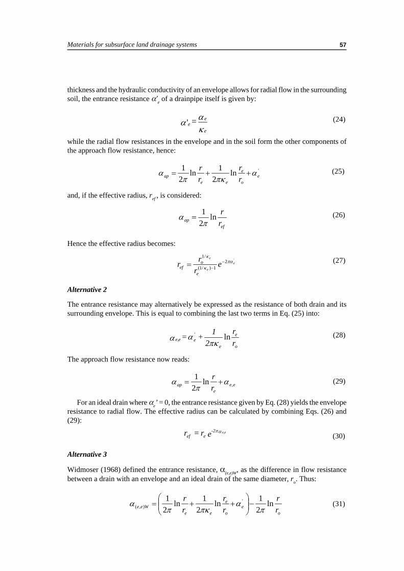
Materials for subsurface land drainage systems 57
thickness and the hydraulic conductivity of an envelope allows for radial flow in the surroundingsoil, the entrance resistance α’e of a drainpipe itself is given by:
καα
e
ee = ' (24)
while the radial flow resistances in the envelope and in the soil form the other components ofthe approach flow resistance, hence:
'ln2
1ln21
eo
e
eeap r
rrr α
πκπα ++= (25)
and, if the effective radius, ref , is considered:
efap r
rln21π
α = (26)
'21)/1(
/1e
e
e
er
rre
oef
πακ
κ−
−=
Hence the effective radius becomes:
(27)
Alternative 2
The entrance resistance may alternatively be expressed as the resistance of both drain and itssurrounding envelope. This is equal to combining the last two terms in Eq. (25) into:
o
e
eeee, r
r2
1+ = ln'
πκαα (28)
The approach flow resistance now reads:
eee
ap rr
,ln21 απ
α += (29)
For an ideal drain where αe’ = 0, the entrance resistance given by Eq. (28) yields the enveloperesistance to radial flow. The effective radius can be calculated by combining Eqs. (26) and(29):
er =r ee,-2eef
απ(30)
Alternative 3
Widmoser (1968) defined the entrance resistance, α(e,e)W, as the difference in flow resistancebetween a drain with an envelope and an ideal drain of the same diameter, ro. Thus:
oe
o
e
eeWee r
rrr
rr ln
21ln
21ln
21 '
),( πα
πκπα −
++= (31)

Water flow into and inside the drain58
which, after some simplifications, finally results in:
α απ κ( , )
' ln lne e W ee
e
o
e
o
rr
rr
= + −
12
1 (32)
while the approach flow resistance is given by:
0),( ln
21
rr
Weeap παα += (33)
Combination of Eqs (26) and (33) yields the effective radius:
er= r e)W(e,-2oef
απ (34)
Though Widmoser (1968) might have given the right definition on the entrance resistanceof a drain with envelope, from the above analysis it is obvious that the effective radius of agiven drain with a well-specified envelope is independent of whatever definition is used for theentrance resistance.
Corrugated plastic drain pipes with a perforation in each corrugation and wrapped with athin envelope ‘sheet’ which spans the corrugations and keep them free from soil makes thedrain surface much more permeable and reduces the entrance resistance considerably (Willardsonand Walker, 1979; Salem and Willardson, 1992). A substantial reduction of the entranceresistance is obtained if an envelope is installed which has a hydraulic conductivity at least 10times higher than that of the surrounding soil. The thickness of the envelope should, preferably,be at least 5 mm (Nieuwenhuis and Wesseling, 1979; Dierickx, 1980). More favourablespecifications do not significantly decrease the entrance resistance any further. Still, greaterenvelope thickness enhances the effective radius, because the soil around the drain is replacedby a comparatively more permeable envelope.
The effective radius of a wrapped drain increases, if the hydraulic conductivity and/orthe thickness of the envelope are made larger. The use of a sufficiently permeable envelope(κe ≥10) which is adequately thick (de ≥ 5 mm) around a plain drain reduces the entranceresistance drastically. If κe ≥10 and de ≥ 5 mm, drains wrapped with envelopes whichhave the same external radius, re, have almost the same effective radius, ref , regardless thepipe radius, ro, and the envelope thickness, de (Figure 32). Thus, it may be more costefficient to select the minimum drain diameter required to satisfy the discharge capacity,and to wrap with a relatively thick envelope, than selecting a greater diameter pipe, wrappedwith a relatively thin envelope. This is because larger diameter pipes are much moreexpensive than a larger amount of envelope material, required to arrive at the same externaldiameter re.
Drain with a less permeable surround
It is generally accepted that drainage works must be carried out under circumstances that do notchallenge the structural stability of a soil. The moisture content of the soil is a critical factorbecause drainage works carried out with trenchers in wet conditions may result in deteriorationof the structure of the excavated soil. As a result, the drain surround becomes less permeablethan that of the surrounding natural soil. Trenchless and mole drainage techniques can locally

Materials for subsurface land drainage systems 59
compact the soil around the drainor mole channel, inducing a lesspermeable zone around it.Invasion of soil particles into theenvelope and/or chemical depositscan result in a partial blocking ofthe pores and a decreasedhydraulic conductivity of theexternal envelope surface.
Experimental research showsthat, if an envelope has asubstantial thickness, e.g. >5 mm,and if its hydraulic conductivity isless than 10 percent of that of thesurrounding soil, the entranceresistance may be very large, andconsequently the effective radiusof the drain reduces to extremelysmall values. This is mainly dueto impeded flow in the lesspermeable layer surrounding thedrain. If the drain is wrapped withan envelope, smearing andcompaction of the surrounding soil influences the entrance resistance less than envelope clogging,yet the effective radius may be reduced to intolerable values.
FIGURE 32Effective radii, ref , for drains of different pipe radii, ro,and provided with four continuous longitudinal slitsas a function of the envelope thickness de for κe = 10
0
10
20
30
40
50
60
70
80
90
0 10 20 30 40 50 60 70
d e (mm)
r ef (
mm
)
20
3025
40
50r o (mm)
80
70
60
50
40
r e (mm)
A less permeable layer surrounding either a plain drain or a drain with a more permeableenvelope has an adverse influence on the performance of drain materials and must thereforebe avoided at all times.
Mutual differences between the entrance resistances of various types of drainpipes may beimportant if these drains are installed without envelope. The hydraulic characteristics of theabutting media (either the soil or the envelope and the soil) are, however, much more relevantthan the specifications of these pipes.
DISCHARGE CAPACITY OF DRAINPIPES
The discharge capacity of drainpipes is an important component of any design procedure forland drainage systems, and is described in all major drainage textbooks. The available informationranges from exhaustive (Cavelaars et al., 1994) to straightforward treatment, which is limitedto the fundamentals only and some useful examples (Smedema and Rycroft, 1983). In thisguide, only the most relevant material is discussed, following Dierickx (1993). Readers whowant to be informed further on the subject are referred to the above publications. Additionalinformation on design procedures (i.e. formulae) in various countries is given in Framji et al.(1987). Pipe diameter nomographs, which are quite useful for a ‘quick scan’ analysis of therequired pipe diameter(s), are given in Smedema and Rycroft (1983). A computer program forcalculating the diameter of drainpipes is in preparation by FAO.

Water flow into and inside the drain60
It is often financially attractive to increase the pipe diameter of collector drains and even oflateral drains in the flow direction. In doing so, the diameter is adjusted for the discharge,which increases in the direction of the outlet. This issue is discussed in depth by Cavelaars(1979), and illustrated in a simple case by Smedema and Rycroft (1983). The forthcomingFAO-publication on drainage design also includes the design of such composite drains.
The hydraulic design of drainpipes is based on formulae that relate the discharge of water tothe pipe diameter, the hydraulic roughness of the pipe wall and the hydraulic gradient. Differentformulae are used for smooth and corrugated pipes.
Clay, concrete and smooth plastic pipes are considered hydraulically smooth pipes. Theirdischarge capacities can be calculated from the Darcy-Weisbach equation. The discharge capacityof corrugated pipes can be calculated from the Chézy-Manning equation. For laterals, a minimumpipe diameter is advisable to compensate for less accurate grade and alignment, and eventuallyfor some settlement that may occur, thus assuring the discharge capacity of the drainage system.In European countries, a minimum diameter of 50 or 60 mm is accepted; elsewhere the minimumdiameter is 80 mm and in the United States the smallest diameter is 100 mm. For collectordrains the length covered by a given pipe diameter for a specified hydraulic gradient is calculated.
In the Chézy-Manning equation, the hydraulic roughness (or ‘friction resistance’) of thepipe wall is expressed as Manning’s coefficient, n, or its reciprocal parameter, kM. For drainpipeswith diameters ranging from 50 to 200 mm and small corrugations, the roughness coefficientn = 0.0143 s m -1/3 (or the reciprocal value kM = 70 m1/3 s-1). From the results of Irwin (1982,1984), Boumans (1988) established that the kM-value of larger diameter pipes with largecorrugations can be expressed as:
kM = 18.7d 0.21S -0.38 (35)
in which d (m) and S (m) are the internal pipe diameter and the pitch length, respectively. Formost pipes with large corrugations, a roughness coefficient n = 0.02 s m-1/3 (or kM = 50 m1/3 s-1)can be accepted.
The type of pipe and the hydraulic gradient determine the discharge capacity of drainpipes.The calculation of the discharge capacity of drainpipes may be based upon two principles(Wesseling and Homma, 1967; Wesseling, 1987):
• the transport principle with uniform flow, whereby a drainpipe is assumed to transport afixed discharge along its length, while the pipe itself is flowing full; and
• the drainage principle with non-uniform flow, whereby a constant inflow of groundwaterinto the drain along its length results in a discharge which increases along the length of thepipe.

Materials for subsurface land drainage systems 61
Corrugated pipes with small corrugations (usually pipes ranging from 50 to 200 mm in diameter)
Corrugated pipes with large corrugations (usually pipes with a diameter beyond 200 mm)
with Q = discharge (m3 s-1);d = internal diameter (m); ands = hydraulic gradient (dimensionless).
All equations are derived for clean pipes. Comparison of these equations reveals that theassumption of the transport principle for the determination of the diameter of drainpipes impliesthat a safety factor is automatically incorporated in the design. The equations based upon thedrainage principle yield larger discharge capacities, and, as such, larger surfaces that can bedrained with a given pipe diameter. Adoption of some safety factor is indeed required toincorporate the risk of possible mineral and/of chemical clogging of the pipe in its hydraulicdesign. Usually, pipes are ‘over designed’ to allow for subsequent partial mineral or chemicalclogging, and for misalignment during installation.
When applying the drainage principle, a safety factor must be imposed because this principleis based on a more realistic physical concept, which leads to a more economical yet riskydesign. For practical application, the discharge capacities as calculated with the formulae basedupon the drainage principle are commonly reduced to 60 percent of the calculated values toinclude a safety factor for possible mineral and/of chemical clogging of the pipe (Cavelaars,1974). This means that, in the end, both principles result in approximately the same dischargecapacity (Dierickx, 1993). For collector pipes, the theoretical capacity is usually only reducedto 75 percent. Hence, an extra safety of 15 percent is built in when using the formulae basedupon the transport principle.
Additional reduction factors up to 50 percent may still be advisable to compensate for pipeclogging, misalignment and an erroneous assessment of the pipe roughness coefficient (El Atfyet al., 1990). The reduction factor may be conservative (25 percent) if corrugated plastics pipeis installed in stable soil, yet must be comparatively large (50 percent) for tile drains laid inunstable soil.
(36) Q = 89 d 2.714 s 0.572 (37)
Q = 22 d 2.667 s 0.5 (38) Q = 38 d 2.667 s 0.5 (39)
Q = 15 d 2.667 s 0.5 (40) Q = 27 d 2.667 s 0.5 (41)
Transport principle Drainage principle
Clay, concrete and smooth plastic pipes
Q = 50 d 2.714 s 0.572
Application of both principles and pipe characteristics yields the following set of equations:

Water flow into and inside the drain62
Too small a drain or a drain partially filled with sediment causes a reduced transport capacity.The pipe section will then be too small for discharging the groundwater properly, and the waterin the drain will be flowing under pressure. Water may be standing above the drain and thegroundwater table midway between drains will be too high. Too small a diameter or a reductionin transport capacity can be observed by a piezometer to measure the water head in the drain,and observation wells for the height of the water table transversal to and near the drain.

Materials for subsurface land drainage systems 63
Chapter 5The problem of clogging of pipes
and envelopes
MINERAL CLOGGING
Processes in soils around drains
A major problem that is often encountered on subsurface drains is mineral clogging of pipesand envelopes. This physical process occurs as the result of sudden drastic changes in soil-water conditions near the pipes caused by their installation. Immediately after installation, anew equilibrium begins to be established at the vulnerable area near the interface between thebackfilled soil and the surface of the drainpipe or the surface of the envelope. The area isvulnerable because the physical strength and the structural stability of the soil has been weakenedby the installation process. Moreover, groundwater starts flowing towards the drain, wherebythe hydraulic gradients and the flux densities, being high in this area, induce substantial dragforces on the soil particles.
Soil movement at the interface between soil and envelope (or pipe wall) caused by flowingwater is often referred to as internal soil erosion. Ziems (1969) made an extensive study of thisphenomenon. He indicated that soil particle movement at the interface between two media maybe, in fact, caused by three different physical phenomena, namely the washing out of fine soilparticles (creating a ‘natural filter’), contact erosion and soil collapse. The physical processleading to the development of a natural filter in a soil has been discussed by various authors(Stuyt, 1982, 1992a; Cavelaars et al., 1994). Another phenomenon, which adversely affectswater entry into drains, is the development of a so-called ‘filter cake’.
The phenomena just mentioned may be characterized, in brief, as follows:
Natural filter. If only fine soil particles are washed out, a coarser soil skeleton is left behindthat bridges over the openings in the drain or in the envelope. The formation of a natural filter,for instance in soil backfilled on top of a granular envelope, is illustrated in Figure 33. The dragforce of the water that flows toward the drain causes small soil particles to move into andthrough the envelope while those of larger sizes are retained (Time 1). After some time, ahighly permeable ‘natural filter’ will develop in the soil adjacent to the envelope (Time 2), withan enhanced hydraulic conductivity. If coarser particles are washed out also, the formation of anatural filter in the soil may be superseded by excessive soil particle movement, which willlocally undermine the physical strength of the soil skeleton. This process, in turn, promotescontact erosion.
Contact erosion means that particles of nearly all sizes are washed out locally, resulting inmodification of the skeleton which transfers the effective stresses within the soil. The result ofcontact erosion is shown in Figure 34. Here, the drag force of the water that flows toward thedrain causes soil particles of all sizes to move into and through the envelope (Time 1). Aftersome time, macropores will develop at the interface between the envelope and the soil(Time 2).

The problem of clogging of pipes and envelopes64
Filter cake. A filter cake is a denselayer of soil particles which developsif suspended, fine soil particlesaccumulate at or near the interfacebetween the soil and the envelope.The greater part of this area is oftenlocated in the soil rather than in theenvelope (Stuyt, 1992a). Figure 35shows the development of a filtercake in the course of which fine soilparticles move toward but do notenter the envelope (Time 1). Manyparticles accumulate in the soil nearthe interface between the soil and theenvelope (Time 2). This conditionoccurs when the envelope openingsare too small and act as a filter forthe small soil particles moving withthe water. The hydraulic conductivityof filter cakes is often considerablysmaller than that of the original soil,because fine soil particles clog thesoil pores at the soil-envelopeinterface.
Soil collapse. When the drag forceof the water surpasses the cohesiveforces and intergranular stresses ofa soil, the soil collapses and mayconsolidate. Soil collapse isillustrated in Figure 36. It shows that,after installation of the drain, thecohesion of the soil prevents soilmaterial from moving toward andinto the envelope (Time 1). At a laterstage, soil aggregates are dislocatedand soil particles move through theenvelope towards the drain (Time 2).Some secondary bridging may occurat the soil-envelope interface thatstops further soil movement into theenvelope.
Soil collapse implies local soilstructural failure, dispersion of soilaggregates and movement of soilparticles of all sizes at the interfacebetween the soil and the envelope.Soil collapse is most likely to occurin heavy, cohesive soils at high
FIGURE 33Natural filter (after Stuyt, 1982)
FIGURE 34Contact erosion (after Stuyt, 1982)

Materials for subsurface land drainage systems 65
hydraulic gradients. The drag force ofthe water and the soil load, induced atdrain depth, may even cause thesaturated soil material near the drain tobe pressed through the envelope andinto the pipe perforations, as a muddysubstance (Van der Louw, 1986; Stuyt,1992a).
Until recently, contact erosion wasconsidered harmful to the successfulfunctioning of subsurface drains (Stuyt,1982). Later observations howeverindicated that a low rate of contacterosion is favourable in that it promotesthe formation of a macropore networkaround the drain. This network plays animportant role in the conveyance ofwater into the drain.
Stuyt (1992a) made a serious attemptto gain insight into the physicalprocesses, associated with mineralclogging. A CT scanner was used toobtain three-dimensional (3-D) digitalimages of soil cores, containing 300 mmlong sections of wrapped drainpipeswith the surrounding soils. After aservice life of five years, 45 drainsections were retrieved from threeexperimental fields, located in areas inThe Netherlands where the soils at draindepth consist of very fine sands: indeedproblem soils with low structuralstability. Each CT-sequence is a 3-D,geometrically precise mapping of theinterior density variations inside drainenvelopes and the surrounding soils. Inthe 3-D images, two major types of soilpores could be distinguished, namelytextural pores inside soil aggregates andmacropores (voids, cracks) whichseparate these aggregates. In 40 percentof all cases, the average macroporosityin the trench was lower than that in thesubsoil. Two types of soil structuralfeatures were found in the subsoil:horizontal layering and verticallyoriented macropores (Figure 37).
FIGURE 35Filter cake
FIGURE 36Soil collapse (after Stuyt, 1982)

The problem of clogging of pipes and envelopes66
In Figure 37, only the relatively permeable areas in the soil around the drain are depicted.There is no relation between soil permeability and the intensity of the grey shading. The latteris induced by image processing techniques in order to facilitate visual interpretation of thehighly complex image. Parts of the Plexiglas rims of both the sample container and the sampleholder of the CT scanner were cut away by image processing techniques.
Not all the permeable areas depicted in Figure 37 are physically connected to the drain and,as such, conveying water into it. Using a 3-D image analysis technique, the areas that areconnected to the drain - the so-called active macropores - could be detected. In Figure 38, theseactive macropores are displayed. The depicted samples in Figure 38 are the same as the onesdisplayed in Figure 37. It can be clearly observed that only a minority of all the detected permeable
FIGURE 37Example of a layered subsoil (left) and of a subsoil with vertically oriented macropores, thathad developed at former root channels (right) (after Stuyt, 1992b)
FIGURE 38Image areas displaying drain envelopes and active macropores (after Stuyt, 1992b)
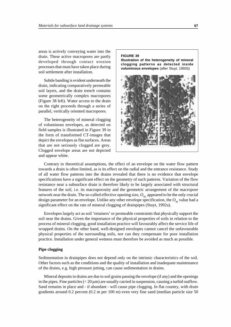
Materials for subsurface land drainage systems 67
areas is actively conveying water into thedrain. These active macropores are partlydeveloped through contact erosionprocesses that must have taken place duringsoil settlement after installation.
Subtle banding is evident underneath thedrain, indicating comparatively permeablesoil layers, and the drain trench containssome geometrically complex macropores(Figure 38 left). Water access to the drainon the right proceeds through a series ofparallel, vertically oriented macropores.
The heterogeneity of mineral cloggingof voluminous envelopes, as detected onfield samples is illustrated in Figure 39 inthe form of transformed CT-images thatdepict the envelopes as flat surfaces. Areasthat are not seriously clogged are grey.Clogged envelope areas are not depictedand appear white.
Contrary to theoretical assumptions, the effect of an envelope on the water flow patterntowards a drain is often limited, as is its effect on the radial and the entrance resistance. Studyof all water flow patterns into the drains revealed that there is no evidence that envelopespecifications have a significant effect on the geometry of such patterns. Variation of the flowresistance near a subsurface drain is therefore likely to be largely associated with structuralfeatures of the soil, i.e. its macroporosity and the geometric arrangement of the macroporenetwork near the drain. The so-called effective opening size, O90, appeared to be the only crucialdesign parameter for an envelope. Unlike any other envelope specification, the O90 value had asignificant effect on the rate of mineral clogging of drainpipes (Stuyt, 1992a).
Envelopes largely act as soil ‘retainers’ or permeable constraints that physically support thesoil near the drains. Given the importance of the physical properties of soils in relation to theprocess of mineral clogging, good installation practice will favourably affect the service life ofwrapped drains. On the other hand, well-designed envelopes cannot cancel the unfavourablephysical properties of the surrounding soils, nor can they compensate for poor installationpractice. Installation under general wetness must therefore be avoided as much as possible.
Pipe clogging
Sedimentation in drainpipes does not depend only on the intrinsic characteristics of the soil.Other factors such as the conditions and the quality of installation and inadequate maintenanceof the drains, e.g. high pressure jetting, can cause sedimentation in drains.
Mineral deposits in drains are due to soil grains passing the envelope (if any) and the openingsin the pipes. Fine particles (< 20 µm) are usually carried in suspension, causing a turbid outflow.Sand remains in place and - if abundant - will cause pipe clogging. In flat country, with draingradients around 0.2 percent (0.2 m per 100 m) even very fine sand (median particle size 50
FIGURE 39Illustration of the heterogeneity of mineralclogging patterns as detected insidevoluminous envelopes (after Stuyt, 1992b)

The problem of clogging of pipes and envelopes68
µm) will stay near the entry point in the pipe. Self-cleaning of the pipe may be expected only atmuch steeper gradients.
CHEMICAL AND BIOCHEMICAL CLOGGING
In subsurface drains, there are four known types of deposits that are associated with bacterialactivity. These are ochre deposits, manganese deposits, sulphur slime and iron sulphide.Gelatinized, voluminous oxidized iron deposits, named ochre, are the most serious andwidespread. Other known deposits are lime and gypsum, which mostly occur in subsurfacedrains of irrigated areas as a result of the chemical composition of the soil and the quality of theirrigation water.
Iron ochre
The gelatinous slimes, associated with ochre deposits are usually yellow, red, or tan in colour.Ochre is filamentous (from bacterial filaments), hydrated (more than 90 percent water), and itsdry matter has a high iron content (2-65 percent dry weight). They usually contain an organicmatrix (2-50 percent dry weight) (Ford, 1979, 1982a).
There are two main categories of ochre problems:
1. Ochre as a temporary problem, called autochthone (of local origin). Temporary ochre asa clogging factor may disappear over a period of three to five years. It usually occurs rapidlyand can be often detected at drain outlets soon after drain installation. If the drains can bemaintained in working order, the concentration of Fe 2+ reaching them will gradually decrease.
2. Ochre as a permanent problem, called allochthone (of foreign origin). Permanent ochre isthe most hazardous condition because it continues to be a clogging agent for the service lifeof the drainage system, regardless of treatment. Permanent ochre occurs in soils that containextensive quantities of residual iron and natural energy. The soluble reduced iron originatesfrom surrounding areas, hence the name, and is transported by seepage into the drainedarea. There are ochre locations where the soluble iron originates 4 to 6 km from a drainagesite. Thus, it is important to consider topographical terrain features when estimating thepotential for permanent ochre formation. In general, sites considered to have permanentochre potential should not be tile-drained without modifications in design and provisionsfor continuous maintenance.
Ochre can be found in the soil abutting the drain envelope, the envelope itself, the pipeperforations and within the drain pipe. Most clogging in corrugated pipes can be traced tosealing of the perforations and accumulations within the valleys of the corrugations. Within thepipes, the heaviest accumulation of ochre appears to be in the lower third of the drain length,although the lower third is usually not the region of maximum ochre formation. Ochre canusually be detected at drain outlets or in manholes as a voluminous and gelatinous mass. However,it may be present in the drains, while not visible at the outlet.
Ochre formation
The development of ochre requires reduced or ferrous iron (Fe 2+) flowing into drains as rawmaterial. The minimum concentration of ferrous Fe 2+, necessary for growth of the iron bacteriumLeptothrix, is 0.12 mg/l (0.12 ppm) (Ford, 1980).

Materials for subsurface land drainage systems 69
It must be in solution in the groundwater rather than located on soil particles. It is presentmostly as iron hydroxide (Fe(OH) 2 ) or as iron sulphide (FeS2), and will precipitate whenoxidation takes place after contact with air, e.g. near and inside subsurface drains (Smedemaand Rycroft, 1983). Many soils contain substantial quantities of iron, yet the conditions, requiredto create ochre problems in drains vary considerably.
Bacteria are required to convert the insoluble ferric iron (Fe3+), which is located on soilparticles, to a soluble form (Fe2+) which can be transported to the drains by groundwateradvection. Ferrous iron (Fe2+) can only exist in groundwater if the oxygen in the soil has beendepleted, e.g. after a soil is flooded for a considerable time, or when micro-organisms haveused all available oxygen. If this condition is met, iron-reducing bacteria reduce the insolubleferric iron (Fe3+). This biological action of the bacteria is energy intensive, and energy sourcesmust therefore be present. The major sources are organic material like remnants of plants andplant roots, and certain acids like malic, citric, tannic and lactic acids. Hence the higher theorganic content in the soil, the faster and more widespread the conversion from Fe3+ to Fe2+ bybacteria will be.
Soluble Fe2+ flowing in groundwater enters a different environment as it approaches thedrain and passes through the drain envelope. If some oxygen is present in this area, certainfilamentous and rod-shaped bacteria will precipitate some of the Fe2+ as insoluble Fe3+ andincorporate it into ochre. Iron-precipitating bacteria must be present for extensive clogging tooccur, even when other conditions are just right for chemical precipitation of the iron. Ironalone does not have serious sticking properties. The reaction inside drains is a combination ofbacterial precipitation and the incorporation of chemically precipitated iron into the sticky slimesof the bacterial masses involved in the ochre matrix.
There is a type of ochre that forms only at low pH, in pyritic soils (acid sulphate soils).These soils are found in many coastal areas as well as in mine dumps and in certain shales.Pyrites are formed from iron and hydrogen sulphide in flooded marine deposits. When suchsoils are drained, the pyrites first oxidize to Fe2+ and sulphates. These sulphates change tosulphuric acid, which lowers the soil pH below 3.5. The rod-shaped bacterium Thiobacillusferrooxidans, which can function only in an acid environment, then converts the soluble ironinto ochre.
In Egypt, Iraq and Pakistan no serious ochre problems have been reported. The absence ofochre there is due to the generally alkaline soil environment. In alkaline soils, ferrous iron (Fe2+)cannot exist in solution in the groundwater. In Israel, severe ochre problems have beenencountered when draining certain swampy areas. The drainage systems were designed suchthat anaerobic conditions were maintained by placing an elbow at the drain outlets to createsubmergence. These systems have operated successfully for several years (Henkin, 1987). Thesame procedure was introduced in The Netherlands in the 1960s, yet with limited success(Huinink, 1991).
Prediction of ochre problems
The following on-site observations may give clues to potential ochre problems inside drains(Ford, 1979):
1. Soil types that appear to show the highest potential for ochre formation are fine and siltysands, organic soils, soils with organic pans and mineral soil profiles with mixed organicmatter.

The problem of clogging of pipes and envelopes70
2. Sites being utilized for sprinkling of sewage effluent usually furnish sufficient energy forreduction reactions. Such sprinkled soils are potentially serious for ochre hazard if the profilesare subjected to long term flooding.
3. Some topographical features indicate possible ochre problems. If there is land of higherelevation close to the proposed drainage site, permanent ochre potential may be a problemdue to permanent seepage. Valleys at the base of escarpments are typical for permanentochre.
4. Flood plains of rivers and gullies are suspect, particularly if the site is a mixture of sand andorganic matter.
5. Depressions containing organic residues are ochre prone sites.6. Blue-coloured clays or bog-like, decomposable organic matter between 0.6 and 1.2 m below
the soil surface suggest permanent ochre sites.7. Oil-like films floating on surface water in canals may indicate ochre and may contain ochre
forming bacterial filaments.8. Gelatinous ochre that has precipitated on ditch banks and/or canal bottoms is an important
indicator for potential ochre problems.9. The amount of Fe2+ in groundwater is usually higher in soils with organic pans and a pH
below six.10.Based on practical experience, the least likely candidates for ochre problems are silty clays,
clay loams and clay soils.11.In arid areas, ochre is seldom a problem.
Ochre potential ratings
It is possible to estimate the maximum potential for ochre before installing drains, as well as toestimate whether specific soil types or profiles can be considered susceptible (Ford, 1982b).Analysing the soils for total iron is of no value because the values do not indicate soluble Fe2+
or the complex interactions between the soil pH and the soil type. The Fe2+-content of thegroundwater flowing into a drain is a reliable indicator of the potential for ochre clogging. Thesimplest way to determine the ferrous (Fe2+) iron content of the groundwater is using paperindicator strips, which are immersed in a groundwater sample. The colour can be used to assessthe concentration of the ferrous iron. The concentrations are colour-coded into the followingclasses: 2, 5, 10, 25, 50, and 100 mg Fe2+/l.
Ford (1982a) developed a reliable yet elaborate testing procedure to assess the ochre cloggingpotential of soil profiles before installing drains. This procedure is independent of pH and soiltype. The method has been developed and tested extensively at numerous locations in the UnitedStates (Ford, 1982a). Using this method, it is possible to determine whether a soil layer mayrelease much or little ferrous (Fe2+) iron, once water saturated, and whether the ferric iron(Fe3+), which is adhered to the soil particles, can be easily reduced to soluble Fe2+.
Scholten and Ven (1987) have compared the ochre potential ratings, assessed with the Fordmethod, with the method using indicator strips. They found a strong correlation of the detectedferrous iron content, determined with both methods. However, the content indicated by thestrips is consistently higher than the content indicated by the Ford method (ratio 3 to 4). Yet, forroutine measurements, the simple method with indicator strips will suffice. In spite of theinsufficient number of readings in their investigations, Scholten and Ven (1987) present a table(Table 8) to assess the ochre potential. The figures in this table are in reasonable agreementwith the figures, proposed by Ford (1982a).

Materials for subsurface land drainage systems 71
How to minimize ochre clogging ofdrains
There is no known economical, long-term method for effectively controllingochre clogging in drains. Althoughoptions are limited, the emphasis mustbe on ‘living with the problem.’ Thefollowing recommendations may beuseful (Ford, 1982a, 1982b).
1. Precipitating iron in the soil by promoting oxidation. Iron cannot be dissolved in groundwateruntil it is reduced. Hence, all measures that minimize the development of anaerobic conditionsare acceptable. Soil aeration prevents reduction. Closer spacing and shallower depth ofdrains may be beneficial for certain sites.
2. Size of the perforations in drainpipes. The larger the pipe perforations, the longer the periodbefore drain discharge may be severely restricted. Ochre adheres to frayed plastic edges ofperforations. Cleanly cut inlet perforations are essential. Small perforations limit theeffectiveness of jet cleaning as a method for cleaning drains installed with synthetic envelopes.
3. Drain envelopes. A graded gravel envelope is best. It may however still clog under conditionsof severe ochre potential. Soil compatible, coarse structured PLMs may also reduce the riskof clogging by ochre. Relatively thin synthetic envelopes like geotextiles present the greatestrisk. Surveys of selected drainage sites show that ochre clogging of drains, wrapped withsynthetic materials occurs first in the slots and valleys of pipe corrugations, and can bepresent in amounts sufficient to cause drain failure. These materials clog relatively easily byochre deposits because the iron precipitating bacteria easily grow across the voids in thefabrics. Of all thin synthetic envelopes, knitted polyester envelopes are the least vulnerableto ochre clogging.
4. Organic envelope materials. Envelopes, manufactured from pine, oak and cypress sawdustdelayed ochre development at drain inlet openings for extended periods in Florida (UnitedStates). Sawdust creates an anaerobic environment and appears to be toxic to ochre enhancingbacteria. Sawdust may contain aromatic hydroxyl compounds that complexes iron. The useof peat and other organic envelope materials should be avoided. They usually increase ochreproblems and enhance clogging.
5. Submerged outlets. Submerged drains in groundwater with high ochre risk prevent the solubleferrous iron (Fe2+) to oxidize to the insoluble clogging ferric iron components (Fe 3+)(Rozendaal and Scholten, 1980). This is an old recommendation that has been used withsome success when the entire drain is permanently under water. The drain line must becompletely under water over its entire length throughout the year. This may require that thedrains be installed on a flat grade or horizontal.
Ochre removal from drains
Data on jetting of drains, wrapped with synthetic envelopes, are scarce. In The Netherlands,medium pressure jetting of ochre clogged drains has generally not been very successful. Thedewatering capacity of jetted drains was not significantly enhanced, or only for a very shortperiod. Jetting water must pass through the pipe perforations and be deflected by the envelopein order to clean the valleys. In structurally unstable soils, the pressure at the nozzle should not
TABLE 8Ochre potential according to the Ford-method andthe method of indicator strips
Ferrous (Fe2+) in groundwater (mg/l)Ochre potentialFord method Indicator strips
Very high >10 >25High 5-10 10-25Moderate 2-5 5-10Little 0.5-2 1-5Negligible <0.5 <1
The problem of clogging of pipes and envelopes72
exceed 20 bar, otherwise the soil near the drains may destabilize and flow into the drain (seeChapter 7, Section Maintenance of drainpipes). The larger the pipe perforations, the better thepotential for cleaning the valleys and envelope. Jet cleaning is unsatisfactory if delayed untilthe ochre has aged and become crystalline and/or sticky. ‘Dry’ rodding (with a scratcher at theend without extra water) can also be applied successfully, provided that:
• the operation is carried out when the ochre is still slimy, before it had the opportunity toharden during a prolonged dry period (summer); and
• rodding is done while the drain is carrying water (wet period). Thus the (still slimy) ochre iseasily loosened and will be carried away by the drain discharge (Cavelaars, personalcommunication).
As ochre clogging is usually most severe shortly after installation, it is recommended to jetthe drains during the first year if ochre problems are suspected, rather than wait until the drainsare clogged. Drains should discharge into open ditches rather than through closed collectorsystems. The access of single drains through open outlets greatly facilitates jetting. Herringboneor similar drain designs should have entry ports for jet flushing.
Lime and gypsum depositions
Whereas ochre is a prominent problem in humid temperate regions, which has been investigatedextensively on a large scale for many decades, the deposition of slightly soluble salts, such ascalcium carbonate (CaCO3) and calcium sulphate as gypsum (CaSO4.2H2O), within drainpipesand envelopes is a not systematically investigated problem. There is ample scope for systematicinvestigation on lime and gypsum depositions with pipe drains; this would include an inventoryof the extent of the problem and the conditions under which it is likely to develop. Lime andgypsum deposition is most likely a chemical process. The hard and crystalline deposits arelikely to build up comparatively slowly so that adverse effects only appear after a long time.
The problem may occur in gypsiferous soils and soils with a high content of calcium carbonate,which are common in arid and semi-arid areas, or result from the salts applied with the irrigationwater. Depending on the dissolved Ca2+-content of the groundwater, it may however also occurin non-irrigated areas like Belgium where CaCO3 is reported to have cemented the gravel arounda drainpipe of a road drainage system to a compact, impervious mass. Calcareous deposits inand around drains installed in soils that convey groundwater rich in dissolved Ca2+ also arereported in France (CEMAGREF, 1983). In arid regions, Cavelaars et al. (1994) found gypsumin excavated drains. No deposition of lime was however found in horizontal drainage systems,in spite of the lime deposition hazard - ‘incrustation’ - of tube wells.
Precipitation of lime and gypsum may take place if the concentration of calcium compounds(carbonates, bicarbonates or sulphates) exceeds their solubility. Many waters, particularly inarid regions, are partly or nearly saturated with calcium bicarbonate, (Ca(HCO3)2), which, uponconcentration, precipitates in the soil as CaCO3. Precipitation of CaCO3, and of CaSO4 willoccur if the soil solution is concentrated by water removal during plant growth, and the solubilityof the relatively insoluble CaCO3 and the more soluble CaSO4 is exceeded.
This physical process does not explain the precipitation of CaCO3 in the drain envelope andat the perforations which may result from the conversion of Ca(HCO3)2 through the loss ofcarbon dioxide, (CO2). For tube wells, the precipitation hazard may be explained by the pressuredecline in the groundwater at the entrance of the envelope or the tube openings.
Complete prevention of the deposition of CaCO3 and CaSO4 in a horizontal drainage systemwill not be possible, yet some measures can be taken to reduce the precipitation hazard of these

Materials for subsurface land drainage systems 73
calcium salts. Keeping drainage systems under water will reduce the risk of more concentratedsolutes near the drainage system and the release of CO2 from the groundwater.
Manganese deposits
Manganese, if dissolved in groundwater under suitable reducing conditions, can form a bacteriallyenhanced, gelatinous black clogging deposit.
Sulphur precipitate
Sulphur slime is a yellow to white stringy deposit formed by the oxidation of hydrogen sulphidethat may be present due to reduction of sulphates dissolved in groundwater. Sulphur bacteriaoxidize the H2S to H2O and elemental sulphur S. Globules of elemental sulphur and masses ofwhitish, sticky slime are deposited within the filaments of these bacteria and forms a precipitateof sulphur at the drain outlets (Martínez Beltrán, 1978; Ford, 1980).
Sulphur slime has not been a serious problem in most agricultural drains. It is found mostoften in muck soils. It may also be present at sites designed for subirrigation through drainpipesif the well water used for irrigation contains hydrogen sulphide (H2S).
Iron sulphide
Iron sulphide (FeS2) may be found under chemically reduced conditions, e.g. when drains areburied in mixed soil profiles, in gullies and river plains, or when topsoil or organic debris areused to cover the drains during installation. It is a gelatinous black precipitate formed by thereaction between ferrous iron (Fe2+) and hydrogen sulphide (H2S). It will usually not stick tolight sandy soil particles. It becomes a clogging agent if it is present in amounts that can blocksoil pores. In general, iron sulphide should not be a serious problem for most installations thatdo not blind the drains with topsoil or debris of organic matter.
PENETRATION OF ROOTS INTO DRAINPIPES
Field data concerning root penetration are scarce. Penetration of roots of field crops is rare inarable lands. Such roots may temporarily obstruct drain discharge and slightly enhance pipesiltation, but they will die after harvesting. Roots are more challenging in drains installed underperennial plants like trees and shrubs, e.g. under shelterbelts, which border orchards. They mayfill the entire drain over a considerable length, trapping suspended materials and seriouslyobstructing drain discharge. Installing unperforated pipe sections at locations where such rootsoccur may prevent the problem (see Chapter 2, Section Rigid pipes).
In arid countries, drains are installed at 1.5 to 2 m depths and occasionally deeper, hence,root growth into the drains is less likely as compared with drains that are installed at shallowdepths.
Quantitative information on root growth inside drains is scarce.
• In Belgium, during a dry spell, deep rooting cabbage caused problems in a shallow drainagesystem that was used to control a perched water table.
• In Egypt, the Eucalyptus tree is known to cause trouble (Cavelaars et al., 1994).
• In Israel, the roots of certain types of Tamarix trees tend to clog drains. The roots of Tamarixand of some other types of trees cannot be removed, especially when gravel envelopes havebeen used (Henkin, 1987).

The problem of clogging of pipes and envelopes74
• In Pakistan, all trees located within a distance of 35 m from the drains were removed as away of precaution in the Mardan Scarp project.
• In Spain, very fine roots of saline shrubs (Suaeda fruticosa) which grow on the banks ofcollector ditches were found to grow into laterals, causing serious clogging. This problemmay be solved by installing unperforated pipe sections with a minimum length of 3 m at thedownstream end where the laterals discharge in these ditches (Martínez Beltrán, 1987).
• In Surinam, an Asiatic vine called kudzu caused substantial problems of root growth insidedrains (Van der Molen, 1972).
• In Peru, sugar cane was reported to grow into pipes at a depth of 1.5 m (Cavelaars, 1987).
• In The Netherlands, the occurrence of roots in agricultural lands is linked to the type ofcrop, the type of envelope, and the site that is drained. Roots penetrated easily into drainswrapped with organic envelopes (a mixture of peat and coconut fibres), glass fibre sheetenvelopes, knitted sock envelopes, and a PLM envelope consisting of polystyrene granules.Thin synthetic envelopes however provided good protection. Root penetration was generallylower when the envelope thickness was greater (Stuyt, 1992a). Fruit trees (apples, pears) donot cause many problems, yet poplar (Populus canadensis) is known to be harmful.
Materials for subsurface land drainage systems 75
Chapter 6Guidelines to predict whether an envelope
is required
Due to the drag force of water flowing toward a drain, soil particles may be carried into thedrain from all sides. Drainpipe siltation may be due to particle invasion of cohesionless soil, tosoil dispersion of cohesive soil at drain level, or to downward transport of dispersed or suspendedmaterial through soil pores, cracks and voids. This process can never be prevented completely,but it can be counteracted by installing an envelope material around the drainpipe. The need ofenvelope materials around drainpipes will depend on the physical and chemical properties ofthe soil, on the chemical composition of the water to be drained and on the conditions underwhich the pipes are installed. However, whether or not a soil presents problems is not easy totell, because it cannot easily be derived from soil properties and conditions. Soil heterogeneityand the complicated nature of the physical interactions between water and soil near drain openingsmake prediction of the need for drain envelope materials very difficult.
Attempts have been made to define and identify soils that are prone to cause mineral cloggingof drainpipes. Although many soil types have been identified as being more susceptible tosedimentation than others, sound criteria as to whether drains require an envelope or not havenot yet been established. With the current state of knowledge, it is virtually impossible todetermine universal criteria and fixed parameters to predict the tendency of mineral drain cloggingfor a given soil and the associated need of an envelope. Nevertheless, the experience gainedduring four decades of investigations and practice allows for a number of conclusions to bedrawn. These are existing criteria, usually based on local experience and only valid for theregions where they have been established. They may therefore not be directly transferred toother regions without verification of their applicability.
Permeameter experiments with soil samples taken at design drain depth may provideinformation on the need of drain envelopes, by giving evidence of the structural stability of asoil and the risk of soil particle invasion into drainpipes. Permeameter research has beenperformed in the United States (Willardson and Walker, 1979; Samani and Willardson, 1981),the Netherlands (Stuyt, 1992a), Belgium (Dierickx and Yüncüoglu, 1982), France (Lennoz-Gratin and Zaïdi, 1987) and is currently being conducted in Egypt, Pakistan, and India.Permeameter experiments on samples of soils and potentially suitable envelope materials arecarried out with increasing hydraulic gradients. If the soil resists high gradients, a drain envelopeis not required. An application is the assessment of the hydraulic failure gradient of a soil (e.g.Samani and Willardson, 1981). From comparison of permeameter results with those of fielddrains, Lennoz-Gratin et al. (1992) consider the permeameter flow test a reliable means topredict mineral clogging of drainpipes. The results of Stuyt (1992b), however, indicate that theassociation between laboratory data and field data may be quite ambiguous.
Apart from laboratory experiments, very simple field observations may give clues to theneed to install envelopes in future drainage projects. Auger holes, intended for the determinationof the hydraulic conductivity of the soil, may yield useful information in this respect. If such
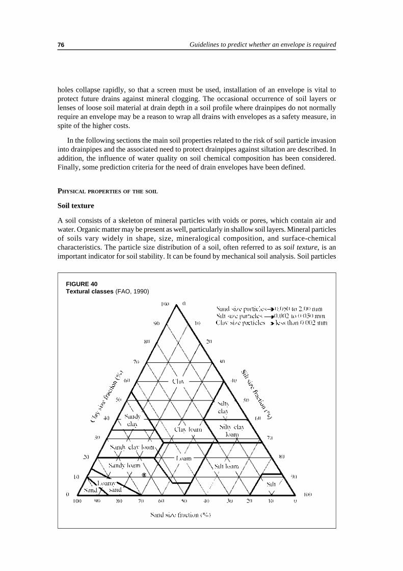
Guidelines to predict whether an envelope is required76
holes collapse rapidly, so that a screen must be used, installation of an envelope is vital toprotect future drains against mineral clogging. The occasional occurrence of soil layers orlenses of loose soil material at drain depth in a soil profile where drainpipes do not normallyrequire an envelope may be a reason to wrap all drains with envelopes as a safety measure, inspite of the higher costs.
In the following sections the main soil properties related to the risk of soil particle invasioninto drainpipes and the associated need to protect drainpipes against siltation are described. Inaddition, the influence of water quality on soil chemical composition has been considered.Finally, some prediction criteria for the need of drain envelopes have been defined.
PHYSICAL PROPERTIES OF THE SOIL
Soil texture
A soil consists of a skeleton of mineral particles with voids or pores, which contain air andwater. Organic matter may be present as well, particularly in shallow soil layers. Mineral particlesof soils vary widely in shape, size, mineralogical composition, and surface-chemicalcharacteristics. The particle size distribution of a soil, often referred to as soil texture, is animportant indicator for soil stability. It can be found by mechanical soil analysis. Soil particles
FIGURE 40Textural classes (FAO, 1990)

Materials for subsurface land drainage systems 77
are normally classified as clay (< 2 µm), silt (2-50 µm) and sand (50-2000 µm). The dry weightpercentages of sand, silt, and clay can be plotted in a triangular graph (Figure 40). Drawingthese percentages on a line parallel to the base opposite to the indicated corner (which represents100 percent sand, silt, or clay) the textural class can be found by the intersection of the threelines inside the triangle. Figure 40 shows that a soil with a clay fraction of 11 percent, a siltfraction of 27 percent and a sand fraction of 62 percent would be classified as sandy loam.
The cumulative particle size distribution curve (Figure 41) gives information on the cumulativepercentage of soil particles (on dry weight basis) that is smaller than a given diameter. Forexample, d10 and d50 are the particle diameters for which respectively 10 and 50 percent of thesoil particles (by dry weight) have a smaller diameter. A uniform soil has a ‘steep’ particle sizedistribution curve (curve ̀ a` of Figure 41), whereas a well-graded soil curve is less steep (curve`b` of Figure 41). The latter has a d10 of 1.7 and a d50 of 105 µm.
The coefficient of uniformity (Cu) of a soil is a measure of the bandwidth of the sizes of thesoil particles that it contains. This coefficient, which is reflected by the inclination or slope ofits particle size distribution curve, is given by:
C d du = 60 10 (42)
The greater the Cu value is, the less uniform or the better graded the soil will be. A uniformsoil, with all particles of the same size, has Cu = 1.
Particle size distribution and soil texture classification can give a first indication of the needfor a drain envelope. For loose soils like sands, the Cu coefficient is often employed to predictthe need for drain envelopes. If the soil is cohesive, the clay percentage is a more significantindicator.
FIGURE 41Particle size distribution curves

Guidelines to predict whether an envelope is required78
In various regions, criteria based on the clay content of a soil have been successful as ameans of determining whether drain envelopes are required. In Quebec, drainpipes do not needenvelopes in soils with a clay content of at least 20 percent (CPVQ, 1989) while in theNetherlands, the clay content should be at least 25 percent (Van Zeijts, 1992). In Egypt and inIndia, the clay content should be 30 percent or higher (Abdel-Dayem, 1987; Rajad ProjectStaff, 1995). Nevertheless, some of these soils still exhibited mineral clogging. This is causedby the fact that soil stability is not only depending on the physical, but also on the chemicalcomposition of the soil (Section Chemical properties of the soil).
In fine cohesionless sandy soils, drains normally require an envelope. However, in Quebec(CPVQ, 1989) no envelope is recommended if the width of the perforations in the pipe wall issmaller than 2 d85 (the particle diameter for which 85 percent of the soil particles by dry weighthave a smaller diameter). Instead of 2, other values of this factor ranging from 0.5 to 10 havebeen accepted as well. Attempts to adapt the perforation width to a characteristic particle sizediameter of the surrounding soil have failed because of the variability of both. Therefore, incohesionless sandy soils, drain envelopes should be recommended under all circumstances.
Although texture alone is insufficient as a decision parameter for envelope application, it isgenerally accepted that soils with d50 between 50 and 150 µm are mechanically quite unstableand, as such, sensitive to erosion (Dierickx and Leyman, 1991). They will therefore require anenvelope.
Given the fact that soils with a great bandwidth of particle sizes do not present serioussiltation problems, Olbertz and Press (1965) proposed the Cu coefficient as an erosion likelihoodparameter:
• 1 < Cu < 5 : very uniform and very sensitive to erosion.• 5 ≤ Cu ≤ 15 : moderately uniform and sensitive to erosion.• Cu > 15 : no danger of erosion.
The ratio clay/silt percentage of a soil is also important. According to Dieleman and Trafford(FAO, 1976), the risk of mineral pipe clogging decreases rapidly when this ratio exceeds 0.5,where the particle size of silt ranges from 2 to 20 µm.
In any case, soils with an important quantity of silt and a small amount of clay offer a greatrisk for mineral clogging of drains. A range of particle size distributions of such soils is presentedin Figure 42. Any soil having a cumulative particle size distribution that lies completely orlargely in the shaded area is likely to cause problems with drain clogging (Stuyt, 1982;Veldhuijzen van Zanten, 1986). The reason is that these soils have particles which are generallytoo big to be cohesive yet not big enough to be stopped from being washed into drain openingsnot protected by an envelope.
Structural stability
In the Netherlands, field data indicate that soils may differ widely with regard to the rate ofmineral clogging even though they have a comparable texture (Stuyt, 1992a). It has becomeobvious, over the years, that the structure of a soil is at least as important as its texture. However,it is rarely possible to interpret soil structure in terms of clogging risks, let alone clogging rates.
Soil structure refers to the way soil particles are bound together into natural, more or lessporous compounds or aggregates. It is conditioned by the soil texture, the presence of organic

Materials for subsurface land drainage systems 79
and other cementing substances, and the ratios between various cations that are present in thesoil. Soil aggregates may be classified depending on the strength of the bonds between soilparticles, which can range from loose, weak, moderate to strong bonds. Soil structure consistingof loose, individual soil particles is typically associated with sandy soils, yet the finer grainedsilts may also exhibit this type of structure. Such soils are structureless and have virtually nocohesion. Clay soils are generally cohesive and may be massive or develop blocky and prismaticstructures. In some cases, however, they lose their cohesion and get dispersed (Section onChemical properties of the soil). Soil structure governs, among other things, water flow towarddrainpipes.
The firmness of the bonds between soil particles is called cohesion. Soil consistency refersto the behaviour of a soil at various moisture contents and largely depends on cohesion. Twowell-known consistency limits are the liquid limit and the plastic limit, which form the so-called Atterberg limits. The difference between these two limits gives the plasticity index (Ip).The Ip index is an indicator for the firmness of the bonds between soil particles.
The structural stability of soil aggregates is related to the attracting forces between thesoil constituents, and determines the resistance of a soil to mechanical and physical-chemicaldestructive forces. To a certain extent, the structural stability of soil aggregates is determinedby the amount of clay particles. Aggregate stability is an important soil characteristic when itcomes to the assessment of the risk of mineral clogging of drainpipes, and it is known thatdrainpipes installed in stable structured soil do not require envelope materials. In spite of theavailability of various methods to determine aggregate stability, e.g. by wet sieving, astraightforward, unambiguous procedure to classify the structural stability of soil aggregates
FIGURE 42Range of particle size distribution of soils that may cause clogging of drains
Guidelines to predict whether an envelope is required80
into significant figures is not available. The reason for that is that stability of aggregates is not anintrinsic property of the soil but depends on various conditions such as moisture content andchemical properties. Slaking of dry soil aggregates upon wetting is well known. However, ifthis soil remains in the plastic state at drain depth, it will largely resist slaking. Hence thestructural stability of a soil is not a very reliable indicator when it comes to derive guidelines forthe assessment of envelope requirement to prevent mineral clogging of drain lines.
The Ip index, mentioned above, is used to predict the sensitivity of a soil to mineral cloggingof a drainpipe. Dieleman and Trafford (FAO, 1976) report the following:
• Ip < 6 : high tendency to siltation.• 6 ≤ Ip ≤ 12 : limited tendency to siltation.• Ip > 12 : no tendency to siltation.
There are various modifications of this approach, sometimes in combination with othercriteria (e.g. Lagacé, 1983).
Moisture content
Under general wetness the structure of the soil is detrimentally affected when a subsurfacedrainage system is installed. Putting drains under wet conditions may destroy the structure of asoil almost completely and enhance the risk of mineral clogging of the pipes. Therefore, drainsshould not be installed under too wet conditions. Unfortunately, stopping the work during wetspells is often ignored for financial considerations. Moreover, drains must sometimes be installedat locations where the groundwater table is permanently above the envisaged drain level.
The warning not to install drains, if possible, during periods of excess wetness, or when thewater table is quite shallow is not new. Cavelaars (1966) was one of the first to mention that theperformance of a drain under field conditions is determined to a far greater extent by the actualcondition of the soil around the drain, than by the type of drain or envelope material. His majorconclusion was that installing drains under wet conditions could have a very harmful effect onthe performance, especially in soils of low structural stability.
CHEMICAL PROPERTIES OF THE SOIL
Structural stability of a soil is affected by its salt and sodium content. In addition, cementingagents in sands and silts are lime (CaCO3) and sesquioxides (Al- and Fe-oxides). Lime precipitatesaround the contact points between soil particles. The binding capacity of Fe-oxides is ill-defined,but Al-oxide is probably effective. Apart from these inorganic deposits, soil organisms andtheir organic by-products may also keep soil particles together.
The chemical composition of a soil is also quite relevant because of potential clogging ofdrainpipes and/or envelopes due to iron, lime and sulphate compounds (Chapter 5, Section onChemical and biochemical clogging). Although drain envelopes cannot prevent chemicalclogging, this phenomenon must be duly considered in any envelope selection procedure.
Assessment of the risk of mineral clogging of drainpipes as a result of the chemicalcomposition of the soil requires knowledge of the cation exchange capacity, and the salinityand sodicity of the soil.
Cation Exchange Capacity
Clay particles and humus have adsorptive properties. Clay particles are colloids that are sosmall that surface effects are dominant. Phenomena affected by soil colloids are dispersion,

Materials for subsurface land drainage systems 81
swelling, shrinkage, flocculation, cohesion, and plasticity of soils. Clay particles have a negativecharge and thus they adsorb positively charged cations such as Na+, K+, H+, Ca2+, and Mg2+.
Organic matter has a stabilizing influence on the physical and chemical properties of soils,despite its generally modest quantity. It promotes the development and the stability of soilstructure. The finer components of organic matter are converted into humus, as a result of theirdecomposition by micro-organisms. Like clays, humus is also a colloidal material. Its capacityto hold ions exceeds that of clay but clay is generally present in larger amounts. Hence, thecontribution of clay to the chemical soil properties usually exceeds that of humus, except invery sandy soils.
If soil colloids contain a high proportion of Ca2+ and other divalent ions, firm bonds areformed between mineral particles, leading to stable soil structure. In soils rich in Na+-ions(sodic soils) the bonds are unstable, which results in a weak soil structure.
The total amount of cations that a soil can adsorb is determined by the negatively chargedsoil colloids clay and humus. This amount is called the Cation Exchange Capacity (CEC) of asoil and usually expressed in meq/100g of dry soil.
Soil salinity
Soils may contain slightly soluble salts such as lime and gypsum and highly soluble salts suchas sodium chloride and sodium sulphate. These salts may be contained in the soil parent material(primary salinization) or be transported dissolved in water and deposited after the soil has dried(secondary salinization). The major sources of secondary salinization are salts added with theirrigation water and through capillary rise of groundwater, mainly if the groundwater table isrecharged by seepage. Salt contained in precipitation is negligible in comparison with the saltcontent of the irrigation water and the groundwater.
The anions predominantly present in salty soils are Cl- and SO42-, yet some HCO3
- at pHvalues of 6-8 and CO3
2- at pH values higher than 8.5 may be found. Na+, Ca2+ and Mg2+ are thepredominant cations.
The total dissolved solids (TDS) can be assessed from measuring the electrical conductivity(EC). The EC-value and TDS are linearly related (Richards, 1954), and given by:
TDS = 640 EC (43)
where TDS = total dissolved solids (mg/l); andEC = electrical conductivity (dS/m).
The electrical conductivity of the soil extract is usually determined in a soil paste saturatedwith water up to the liquid limit. This conductivity (ECe) is comparatively easy to measure. Formost soils the EC of the soil solution at field capacity (ECs), some time after a rain or irrigation,is about twice the ECe-value.
Soil sodicity
The relative amount of adsorbed Na+-ions, compared to the total amount of cations that a soilcan adsorb is called the Exchangeable Sodium Percentage (ESP):
ESP (%) = (Na+ads/CEC) × 100 (44)

Guidelines to predict whether an envelope is required82
where Na+ads is the quantity of adsorbed Na+-ions (meq/100 g of dry soil). The ESP expresses
the sodicity and hence the dispersion tendency of a soil.
Information on the chemical properties of the soil adsorption complex can be obtained fromthe soil solution since there is equilibrium between the adsorbed cations and the dissolvedcations. Hence, another measure for the sodicity is the Sodium Adsorption Ratio (SAR), derivedfrom the concentration of sodium, calcium, and magnesium in the soil solution.
(45)
where the cation concentration is expressed in meq/l.
The SAR can be determined more easily than the ESP. The ESP can however be calculatedeasily from the SAR since they are related as (Richards, 1954):
)01475.00126.0(1)01475.00126.0(100(%)
SARSARESP
+−++−
= (46)
Within the range 2-30, SAR and ESP values are almost equal, so SAR = ESP is a practicalapproximation. Outside this range, Eq. (46) must be used.
High ESP or SAR values are usually an indication of poor physical soil conditions and highpH. An easy field method, therefore, is testing pH with the indicator phenolphthalein. If thisturns pink (pH above 8.5), the soil has probably a high ESP.
Dispersion problems are generally more severe when the ESP or SAR values are greater.Dispersed material may be transported by groundwater and will enter the drainpipe. In general,under arid climates, problems are not experienced in soils with ESP values below 15 percent.In India, the clay content of soils, for which no envelopes around drains are required, is increasedfrom 30 to 40 percent for soils with SAR exceeding 13 (Rajad Project Staff, 1995).
As the salt concentration of the soil solution has an influence on dispersion, the ESP of asoil cannot be used as a single indicator of soil stability. Soils having an ESP greater than 15percent will not disperse as long as the salt concentration in the soil solution is high. When thishigh salt concentration in the soil solution decreases, e.g. due to leaching by rain or irrigationwater, dispersion problems may arise (Smedema and Rycroft, 1983).
The sensitivity of soils to dispersion also depends on the type of clay mineral (swelling ornon-swelling type of clay). Swelling clay types are more susceptible to dispersion problemsthan non-swelling clays. But vertisols (strongly swelling and shrinking clay soils) in Gezira,Sudan and elsewhere, are examples of soils which do not exhibit dispersion problems in spiteof ESP-values ranging from 20 to 25 percent (Smedema and Rycroft, 1983).
In humid areas, where leaching by rain water is dominant, difficulties with soil structuremay already arise at ESP-values as low as 5 percent, whereas soils leached by irrigation waterwill usually tolerate 10 percent ESP (cf. Table 9).
2
++++
+
+=
MgCaNaSAR

Materials for subsurface land drainage systems 83
WATER QUALITY
The chemical composition of a soil largely depends on the quality of the irrigation water, theamount of rainfall and on the chemical composition of the groundwater. The latter may berecharged by irrigation water, rainfall or seepage, causing the water table to rise far enough toinfluence the soil.
Irrigation water
The stability of the soil structure in the arable layer and the root zone depends in the long run onsalts added with the irrigation water. In the long run, the EC and SAR of the soil solution at fieldcapacity (ECs and SARs) depend on the EC and SAR of the irrigation water (ECiw and SARiw)with which the soil has been irrigated:
ECs = n ECiw (47)and
(48)
where n = factor of concentration of the irrigation water in the soil. It depends on the leachingfraction (the fraction of irrigation water drained).
For high leaching fractions (LF ≈ 0.3) the n-value is approximately 2. If the EC and SAR areexpressed in terms of the saturated paste ECe ≈ ECiw and SARe ≈ SARiw (Ayers and Westcot,FAO, 1985). For medium leaching fractions (LF ranging between 0.15 to 0.20) ECe ≈ 1.5 ECiwand SARe ≈ 1.22 SARiw.
The effect of the quality of irrigation water on the stability of soil structure may be diagnosedon the basis of its ECiw and SARiw -values. Guidelines to evaluate the impact of the chemicalcomposition of irrigation water on the infiltration rate of water into the soil were given byAyers and Westcot (FAO, 1985). These guidelines, which are summarized in Table 9, may beused to assess the effect of the quality of the irrigation water on soil stability in the arable layerand the root zone.
TABLE 9Problems with the infiltration rate of water into a soil as related to SARiw and ECiw of irrigationwater (after Ayers and Westcot, FAO, 1985)
Irrigation with water of low salinity will decrease soil stability if the salt concentration of thesoil solution is substantial. Rainwater dilutes the soil solution and may cause greater dispersionthan most irrigation waters.
Groundwater
Salinity problems and dispersion of clays, as encountered in irrigated agriculture, are veryfrequently associated with an uncontrolled water table within one to two metres below theground surface. If the groundwater is too close to the surface, it rises by capillary action in dry
ECiw (dS/m)SARiwNo problems Moderate problems Severe problems
0 – 33 – 6
6 – 1212 – 2020 – 40
> 0.7> 1.2> 1.9> 2.9> 5.0
0.7 – 0.21.2 – 0.31.9 – 0.52.9 – 1.35.0 – 2.9
< 0.2< 0.3< 0.5< 1.3< 2.9
iws SARnSAR =
Guidelines to predict whether an envelope is required84
periods and salinizes the soil surface. If the groundwater contains salts, a continuous load of saltaccumulates into the root zone. The combination of high groundwater with salts especiallyarises in places where upward seepage occurs. Unless the excess groundwater is removed by anadequate drainage system its level must be kept below the critical depth. This is the depthbelow which capillary rise can be neglected: about 1 m in sands (because of low capillary rise),about 2 m in most clays (where the velocity is limiting), and 3 m or more in silt loams (withhigh capillary rise and sufficient velocity).
If the groundwater table is controlled by a subsurface drainage system, both the EC and SARof the groundwater (ECgw and SARgw) may have a profound effect on the structural stability ofthe soil at drain level. This is because the EC and the SAR of the soil solution will be similar tothe ECgw and the SARgw if the soil at drain level is permanently saturated. However, the EC andthe SAR of the soil solution may be substantially higher if the soil at drain level is unsaturated,and salt accumulates due to capillary rise.
Effective salinity control must therefore include not only adequate drainage to control andstabilize the water table and to prevent salt accumulation in the shallow soil layers, but also anet downward movement of water to prevent salinization by capillary rise.
PREDICTION CRITERIA
The prediction criteria defined in the above sections are summarized below. These rules aremerely guidelines or recommendations that do not guarantee 100 percent certainty.
• If at drain depth, auger holes can be made only with the use of a screen, because their wallscollapse rapidly, installation of an envelope is vital to protect future drains against mineralclogging.
• In cohesionless sandy soils drain envelopes should be recommended under all circumstances.
• Any soil having a cumulative particle size distribution that lies completely or largely in theshaded area of Figure 42, is likely to cause problems with clogging of drains without envelopes.
• In temperate areas, drainpipes do not usually need envelopes in soils with a clay content ofat least 20-30 percent, providing that drains are not installed under general wetness.
• Soils with a plasticity index of at least 12 show no tendency to siltation.
• In irrigated areas, drainpipes installed in soils with a clay content exceeding 40 percent donot need an envelope, regardless the SAR of the soil solution.
• The need for an envelope in soils with a clay content ranging from 20 to 40 percent dependson the ESP, which is approximately equal to the SAR of the soil solution (or somewhathigher). This SAR is greatly influenced by the quality of the irrigation water and sometimesby the groundwater composition (the latter in case of dominant capillary rise). Generally, noenvelope is required in all cases where SARiw and ECiw appear to exclude soil stability problems,following the guidelines specified in Table 9. In cases, where SAR and EC of the irrigationwater and/or groundwater will presumably invoke soil stability problems, an envelope isrecommended.
• If there is net upward movement of saline groundwater there will be problems with salinizationand dispersion of clays. Maintaining a net downward water movement is the key measure toavoid such problems in soils with or without drainage systems.

Materials for subsurface land drainage systems 85
Chapter 7Guidelines for installation and
maintenance of drainage materials
INSTALLATION OF SUBSURFACE DRAINAGE MATERIALS
Installation procedures
Drainage machinery
The success of a drainage system does not only depend on the design and the properties of thesoil and the envelope. It is also determined by soil wetness during installation, trench backfillingand the general quality of the work.
Manual installation of drains and installation with backhoe machines are a valid optionfor small drainage projects. Backhoes make wider trenches than drainage machines commonlyused in large projects. They are also used for wide and deep excavations for large collectors.Drainage machines either make narrow trenches in which the drains are laid (trench method) orthey put the drain directly into the ground (trenchless method). Trenching machines are eitherwheel or chain trenchers. They are appropriate for a wide range of working depths and widths.Trenchless machines can be classified in either vertical or V-ploughs. The trenchless installationmethod, however, has some practical limitations with respect to drain types, drain sizes, gravelapplication and installation depth. Therefore, trenchless drainage has not yet been widelyimplemented in irrigated areas (Zijlstra, 1987).
Installing drains by manual labour or with classic excavators requires a series of successiveoperations: excavating the trench, installing the pipe, applying the envelope material and backfillingthe trench. These operations are done simultaneously by trenching machines. Sometimes,backfilling is done by a separate auger or blade on a tractor. Backfilling can also be done by animplement, attached on the drainage machine when driving backward to begin excavating anew trench (Ochs and Bishay, 1992).
Contemporary drainage machines are equipped with laser grade control, which has significantlycontributed to the efficiency and accuracy in the installation of subsurface drains. The maximumdigging speed, however, should be adjusted to the speed of the hydraulic system that is used forautomatic depth regulation, otherwise the installation accuracy will be poor. Although a certaindeviation from the design grade can be tolerated, it should not exceed half the pipe diameter.Larger deviations promote air locks in high and sedimentation in low places, which obstructwater movement through the drain. Similarly, drain sections with a reverse grade cannot betolerated.
Blinding
Since the risk of sedimentation is largest during installation and in the immediate subsequentperiod as long as the backfill has not settled and stabilized, drains are normally covered with

Guidelines for installation and maintenance of drainage materials86
friable topsoil to create a stable and highly permeable soil surround, and to preserve the alignment.Therefore trenching machines are equipped with cutters to bring a layer of topsoil or soil fromanother suitable layer from the sides of the trench on top of the drain. Its thickness should be atleast 100 to 250 mm, depending on the drain diameter. Granular envelope material (like gravel)can also be used to achieve a highly permeable drain surround and to prevent vertical andhorizontal displacement once the pipe is installed. Any envelope material to be used must be inplace around the pipe before blinding is done.
Blinding, the initial covering of the drain with topsoil, is not recommended when organicenvelopes are used, because topsoil with organic matter and intensive microbiological activityenhances the risk of microbiological decomposition of these envelopes. In such cases, soil fromanother suitable layer, with low organic matter, can be used for blinding. Further backfilling ofthe trench should be done as soon as possible and, at the latest, at the end of each day if thereis a risk of surface water entering the trench.
Soil conditions
Since soil cohesion is strongly correlated with its water content, installation of the drainagesystem should preferably be done in unsaturated soil conditions with the water table belowinstallation depth and outside periods of general wetness. In addition, the backfill should havesettled before heavy rain or irrigation. In some situations, however, these conditions are not, orcannot be fulfilled. Drainage installation in wet conditions is discouraged, yet it is not alwayspossible to drain under favourable or ideal circumstances.
When cohesionless soils are drained in saturated conditions, an envelope must be wrappedimmediately around the drain and the drain covered with backfill material before the liquid sandflows into the trench. Caving of the trench wall, which often occurs in cohesionless or lowcohesive soils, may damage and/or displace the drain. In every case, the drain and the envelopeshould be in place before the trench box has passed. Possibly, a longer trench shield may beused to protect a greater length of the trench. The drain should be blinded immediately.Simultaneous and instantaneous backfilling will help to prevent trench wall failure. However, thetrench may collapse as soon as the trench box has passed and, therefore, a chute should beprovided at the end of the trench box to convey the caving soil down to the top of the drain inorder to avoid damage by falling clods and stones.
In cohesionless soils, drainage machines should be kept moving at all times. If not, fluid sandis likely to enter the trench box and cause problems with sedimentation as well as with alignmentand grade of drains (Ochs and Bishay, 1992). Many problems, encountered with trenchers orbackhoe excavators in saturated cohesionless soils, can be avoided by trenchless drainageinstallation.
Drainage of physically stable, well-structured soils under general wetness may destroy thesoil structure during excavation and create a less permeable trench backfill (Stuyt, 1992a).Moreover, such conditions also promote mineral clogging of pipe and envelope. In any case, theuse of an envelope cannot compensate for the ‘adversely affected’ soil conditions. Every effortshould be made to preserve the existing soil structure and to protect the drain from soil failure.Adjusting the forward speed of the machine can be done to limit the destruction of the soilstructure. Observation of the condition of the excavated soil can be a guide to the proper machinespeed. The machine should move fast enough to preserve the structure of the soil and not turnthe excavated soil into slurry (Stuyt and Willardson, 1999).

Materials for subsurface land drainage systems 87
Structural deterioration of an originally stable, well-structured soil can be avoided withtrenchless drainage installation. The functioning of drains installed with the trenchless techniquedepends very much on the changes in soil structure brought about by the passing of the blade(Zijlstra, 1987). This depends on the soil, the circumstances (not wet) and the depth (not overapproximately 1.5 m). Drainage of clay soils in wet conditions will unavoidably result in smearingand reduction of the hydraulic conductivity where the machine has physical contact with thesoil. Drainage of cohesive soils in wet conditions must be avoided, regardless of the availabledrainage machine.
The installation conditions for laterals of a composite drainage system in saturated soil areimproved if the time span between the installation of “permeable” collectors and installation ofthe laterals is long enough. This is because much of the local groundwater has the opportunity todrain out before the laterals are installed. In severe cases, where the construction of collectorsis difficult because of quicksand, a temporary drain (at greater depth) may be helpful. It isusually far cheaper than using well-points.
Backfilling
Backfilling and finishing of trenches should ensure a minimum of later land subsidence andpreclude the occurrence of piping. The piping phenomenon may occur as a result of internalerosion of trench backfill by water flowing from the soil surface directly to the drains throughthe loose backfill material (Van Zeijts and Zijlstra, 1990). This is crucial in irrigated lands, whereirrigation water that can flow freely through the trench or drain plough fissures into the drainpipe,will dramatically lower the irrigation efficiency. Furthermore, soil piping may cause soil materialto be carried by the flowing water into the drain, creating sinkholes at the soil surface and/ormineral clogging of drains and envelopes, if present. Proper backfilling of the trench or ploughfissures is therefore essential. It is easier to backfill and compact V-plough fissures than trenches.Fissures, created by vertical ploughs cause the most problems (Van Zeijts and Naarding, 1990).
Neither heavy loads, nor significant flooding should be imposed on newly installed drains untilthe soil in the trench is consolidated. The loose backfill material will settle naturally with time.Since backfilling is usually done with a tractor equipped with a dozer blade, passage of thetractor wheel over the backfilled trench, filling it up, and running over it again will speed up theprocess, yet care must be taken to avoid crushing the pipe. This procedure ensures that only thetop part of the trench backfill is compacted, and that the deeper part of the backfill retains agood permeability and a low entrance resistance. In case of trenchless drain installation with avertical plough, compaction of the upper part of the disturbed soil is equally important. A commonprocedure is that one track of the drainage machine runs over the drain line on its way back tothe outlet drain to begin installing the next lateral. In dry soil, the rate of compaction followingthis procedure may not be sufficient. Application of irrigation water to unconsolidated materialin trenches to settle the backfill is a practice that should be done very cautiously, however.
If a field is to be flood irrigated before the trench backfill is consolidated, direct entry ofuncontrolled surface water into the trench should be avoided by raising temporary ridges alongboth sides of the trench (Stuyt and Willardson, 1999).
Guidelines with respect to drainpipes
Trenching machines can install clay, concrete, or plastic pipes. Clay and concrete pipes aremanually placed on a chute that conveys the tiles down into the trench shield where theyautomatically move into the right position on the bottom of the trench. The tiles should be installed

Guidelines for installation and maintenance of drainage materials88
in the trench in such a way that a perfect junction between drains is obtained. For drains oflarger sizes, an inspector, standing or sitting in the shield, checks for correct laying. The maximumgap between drains may not be more than 3 mm except for sandy soils or soils with a sandylayer on drain depth where it should be not more than 2d85. Clay and concrete tiles withoutgravel or appropriate synthetic envelopes are not recommended in cohesionless fine sand (CPVQ,1989).
Plastic drains are normally fed through a conducting pipe, mounted just behind (wheeltrencher) or above (chain trencher) the digging mechanism of the trencher. Trenchless machineshave been developed to install only corrugated drains of not too large a diameter. They shouldnot be installed with a curvature radius less than five times the pipe diameter, particularly if thepipe is wrapped with an envelope.
For machine installation, the quality of drainpipes is of utmost importance. Drainpipes withfissures, cracks or other visible shortcomings and badly formed pipes or torn envelope material,which do not allow a proper installation or assure a reliable performance, should not be used.Furthermore, all drains and collectors must be closed at the upward end to avoid soil invasion(see Chapter 2, Section End caps). Failures that may occur during installation of corrugateddrains are crushed or collapsed pipes, twisted pipe sections, couplings pulled apart and snapped-off pipes (Van Zeijts and Zijlstra, 1990). In such cases, the discharge is obstructed. Although thewater may finally find its way through the soil to a properly functioning downstream part of thedrain and to neighbouring drains, stagnation occurs. Upstream the blockage, water may standabove the drain and a higher groundwater table will result.
Coils of smaller diameter pipes are usually carried on a reel on either trenching or trenchlessmachine and wound off as installation proceeds. Larger diameter pipes are usually laid out onthe field beforehand, and then guided through the trenching machine.
Excessive pulling can result in connections becoming loose or pipes breaking off. During theuncoiling of the pipe, pipe breakage can be easily overlooked, yet the missing piece of drain willcause local wetness. Therefore, trenchless drainage machines must be equipped with guides tofacilitate smooth entrance of the drainpipe into the feeder tube. Gravel envelope application canentail substantial, undesirable elongation of the drainpipe if the gravel does not flow smoothlydownward through the supply tube.
While cleaning corrugated PVC drains by jetting (Section Maintenance of drainpipes), it issometimes observed that drains were not laid in a straight line, but spiralled slightly. Thisphenomenon is attributed to the tension in the pipe material generated in the unwinding of therolls at installation (Van Zeijts, 1987), and may enhance the development of unwanted airlocksinside the drain.
PVC pipes should not be installed at temperatures below 3°C because of their brittleness atlow temperatures. Storage at temperatures exceeding 40°C for PE and 80°C for PVC pipes, aswell as installation at temperatures above 40oC should be avoided in order to prevent pipedeformation as a result of load and longitudinal stress. Exposure to UV rays of solar radiationalso affects the strength properties of corrugated plastic pipes (Desmond and Schwab, 1986;Dierickx, 1998a). Stored pipes should therefore be protected from the influence of direct sunlightif not installed within one week (tropical climates) or one month (temperate climates) afterdelivery (see Chapter 2, Section Plastic drainpipes).

Materials for subsurface land drainage systems 89
Guidelines with respect to envelopes
Whatever envelope material is used, and by whatever method it is installed, envelopes must fullysurround a drainpipe, unless the drain is installed on an impervious layer. An envelope merely ontop of a drain does not suffice because mineral clogging also occurs from underneath if waterenters the drain from all around. Bulky envelopes can be spread out by hand in the bottom of thetrench before the pipe is placed, but this is only possible in stable soil where trench walls do notcollapse. If drains are laid by hand and a layer of the bulky envelope should surround the drain,the envelope is placed on the bottom of the trench and levelled first. Next, the drain is installedand covered further with bulky envelope to the required height. This also holds for machineinstallation of drains with a bulky envelope. Envelope strips, delivered on rolls, should be appliedbelow and on top of the drain. The material at the bottom needs not necessarily be the same asthe material on the top. Prewrapped drains, however, are preferred since they protect drainsfrom all sides, and offer a greater safety than bulky envelopes or envelope strips can do. Envelopesthat are good and reliable, however, will only be successful if properly installed under favourablephysical soil and weather conditions. Slurry in the bottom of a trench will cause immediate andcomplete failure of the envelope material and hence of the drain.
The general use of gravel envelopes has decreased continuously in spite of all efforts tomechanize and perfect installation by e.g. introducing a gravel auger at the end of the trenchbox. This gravel auger reduces pipe stretch but gravel-feeding problems are still not completelysolved (Vlotman et al., in press). Theoretically, it is also possible to apply gravel with the verticaldrain plough as well as with the V-plough. However, the risk of stagnation of gravel in the supplytube of the machines makes the trenchless technique less suitable for gravel installation. Theinstallation of gravel remains a difficult and labour-intensive operation. Practical experienceshows shortcomings causing base soil intrusion and pipe siltation. The major shortcomings are(Dierickx, 1993):
• segregation during transportation and installation;• flow problems in the supply tube;• unequal distribution around the drainpipe; and• accidental incorporation of soil into the gravel on the bottom of the stockpile.
Coarse, well-graded sand can also be used as a drain envelope. However, the shear resistanceof sand, especially if it is not completely dry, will hamper mechanical installation even moreseriously than gravel does.
Organic and synthetic envelopes, pre-wrapped around corrugated drainpipes can be installedadequately with both trenching and trenchless machines. They are however prone to damage,caused by transport and/or rapid machine installation, especially when materials of inferior qualityare used or when the pipe is not carefully wrapped. In order to avoid local spots of soil particleinvasion, prewrapped envelopes cover the entire drain circumference. Furthermore, they shouldnot be damaged during handling and installation. Therefore, the layer of loose material beforewrapping should be sufficiently thick and as uniform as possible to avoid open spots.
Geotextiles that are used for the wrapping of drainpipes are usually supplied on rolls. Thesheets should be wide enough to facilitate adequate overlap so that the pipes are completelywrapped, without open joints. If both longitudinal edges of a geotextile sheet are sewn, the sheetshould be wide enough to facilitate this. If a geotextile sock is pulled manually over the drain laidout on the field, both the geotextile and the seam, if any, should be strong enough to resist this

Guidelines for installation and maintenance of drainage materials90
handling without damage. Geotextiles usually have adequate mechanical strength to resistmechanical loads during installation.
Machine installation requires adequate drainage materials to assure a straightforwardinstallation and a proper drainage performance. Therefore high-quality materials are requiredand their properties need be checked prior to installation according to well-considered standardspecifications. Quality standards of drainpipes and drain envelopes are therefore of paramountimportance (Chapter 9). Neither PLMs nor prewrapped geotextiles show particular problemsduring installation with both trenching and trenchless machines. Their light weight makes themsuitable in soft soils where the use of gravel creates problems because of the weight of thegravel.
MAINTENANCE OF DRAIN PIPES
Jet flushing
Maintenance is obvious when there is severe clogging. If done regularly it may extend theservice life of the system and enhance its performance. In case of light obstructions in pipes(like fresh ochre) dry rodding may be helpful: a long series of coupled rods, with a scratcher atthe end, is pushed into the drain and removed later. If done during a period of considerabledischarge, the loosened materials will be discharged. For more serious forms of clogging, jetflushing has to be used. Jet flushing is a technique used to remove clogging and precipitatingagents (e.g. soil particles and microbiological deposits, including iron ochre) from drainpipesthrough the impact of water jets. More particularly, the functions of jet flushing are:
• lifting of blockages inside the pipe drain;• removal of deposits from the inner wall surface of the drain;• cleaning of clogged perforations;• removal of loose smaller roots of agricultural crops and weeds; and• supply of sufficient water to carry the loosened agents, including sand and clay particles
towards the drain outlet.
Ideally, the water that discharges from the drain evacuates the major part of the cloggingagents. Particles, larger than approximately 75 µm may be dislodged, yet are generally tooheavy to be removed from the drain (Busser and Scholten, 1979). It is not clear to what extentpipe perforations can be cleaned efficiently and non-destructively. It is assumed that jet flushinghas a negligible effect on clogged envelopes.
A typical jetting device is operated from the power takeoff of an agricultural tractor. Itconsists of a pump, a suction pump inlet, and a reel with a 200-400 m long pressure hose fittedwith a nozzle, as shown in Figure 43. The nozzle is fed into the pipe drain from the downstreamend. Therefore, the pressure hose is pointed to the drain outlet with the help of an adjustablehose guide. Access of the outlets of laterals is easy if they discharge into open collector ditches.Contrary to these singular drainage systems, as common in humid temperate zones, drainagesystems in semi-arid countries often have a composite layout, whereby laterals discharge intopipe collectors instead of open collectors. If the junctions between laterals and collectors arelocated at manholes, these can be used to accept a jetting hose, provided that the diameter of themanhole is at least 0.3 m. In some countries, e.g. Egypt, laterals are accessible at their upstreamend (Figure 14).

Materials for subsurface land drainage systems 91
On average, jetting requires 1-2 m3 of water per 100 m of drain. The water can be pumpedfrom a drainage ditch, an irrigation supply canal, or a tanker must supply it. Saline water is aharsh and corrosive environment for flushing machines. If saline water must be used, the flushingmachine should be made of high quality salt resistant machine parts. The use of salt water forflushing must be avoided: it damages the soil structure around the drain and it is harmful for themachine.
During the jetting procedure, the nozzle must be inserted into the pipe as fast as possible. Thepulsating action of the piston pump enhances the forward movement of the nozzle. After the
FIGURE 43Jet flushing with a medium pressure unit (after Bons and Van Zeijts, 1991)

Guidelines for installation and maintenance of drainage materials92
nozzle has reached the upstream end of the drain, the hose is retreated by reeling, at a steadypace of approximately 0.3 m/s while pumping continues (Van Zeijts and Bons, 1993). The cleaningaction is influenced by the cleaning force, the angle of attack of the water jets, the duration ofcleaning, the water temperature and the use of chemicals (Heeres et al., 1985). The cleaningforce is proportional to the flow rate times the square root of the water pressure at the nozzle(Lechler, 1980). Environmental restrictions as well as cost considerations generally preclude theuse of chemicals while jetting.
A balance must be found between the pressure and the flow velocity of the water jetscoming from the nozzle, preferably on site. The optimum ratio is likely to depend on the insidediameter of the drains; however, no data are available to support this assumption. On manycommercial jet flushing units, the ratio between flow rate and pressure can be adjusted. Flowrates are adjusted by changing the pumping speed. The water pressure is adjusted by selectingan appropriate nozzle (number, size and orientation of holes).
Jet flushing will temporarily increase the water pressure in the drainpipe and thus in thesurrounding soil, possibly affecting soil stability around the drain. The increased water pressurecauses a reduction of cohesive forces between soil particles, which may lead to instant andhazardous quicksand conditions. Notably in weakly cohesive soils, there is a risk of the developmentof quicksand. After the nozzle has passed, structureless soil material may flow into the pipe. Inaddition, the hydraulic conductivity of the soil may be adversely affected. Regardless of thedischarge from the nozzle, dislodged substances are more easily evacuated from small thanlarge diameter drains due to the higher flow velocities in the smaller diameter pipes.
As far as the water pressure is concerned, three categories of jet flushing units are beingmanufactured:
• high pressure equipment : > 100 bar at the pump;• medium pressure equipment : 20-35 bar at the pump;• low pressure equipment : < 20 bar at the pump.
High-pressure units cannot be recommended, because empirical experience evidenced thatthis type of flushing machine destabilizes the soil around the drain and destroys its structure.
Water pressure at the nozzle is approximately 50 percent of the pressure at the pump. Hydraulicdata of nozzle, pump pressure, and flow rates provided by a commercial flushing unit manufacturerfor a flexible hose with an inside diameter of 20 mm and a length of 300 m, are given in Table 10(Bons and Van Zeijts, 1991). The highlighted line contains recommended figures (i.e. pressuresand discharges).
TABLE 10Relation between pump pressure, nozzle pressure and discharge for a flexible hose with an insidediameter of 20 mm and a length of 300 m (after Bons and Van Zeijts, 1991)
Nozzle with 2-mm holes Nozzle with 1.5-mm holesPump Pressure(bar) Pressure at nozzle
(bar)Discharge(l/min)
Pressure at nozzle(bar)
Discharge(l/min)
20 3.2 47 6.0 5025 4.5 65 8.5 5630 5.5 70 10.0 6135 6.7 76 12.5 6740 8.0 82 14.5 7145 9.5 87 16.5 7650 10.0 90 18.5 80

Materials for subsurface land drainage systems 93
The maximum flow of water that can be employed depends on the cross section of the drain.Empirically it was found that a discharge of approximately 70 l/min is satisfactory for 50 to 70mm pipe diameters. Such discharges are indeed realized with the highly popular medium pressureunits. Higher discharges may force too much water through the pipe perforations, which ishazardous for the envelope and the structure of the abutting soil.
The cost/benefit effects of regular maintenance of drains by jet flushing are hard to quantify.Still, some figures may be informative. The cost of jet flushing in The Netherlands, at mediumpressure, is approximately US $0.15 per m of drain which is 12 percent of the installation cost of$1.25 per m. With a typical drain length of 800 m per hectare and a flushing frequency of oncein every three years, the annual cost amounts to $40 per hectare per year. The average annualgross yield of arable land is approximately $2500 per hectare. The calculated maintenance costis therefore less than 2 percent of the annual gross yield.
Empirical experience with jetting in northwestern Europe
Dry rodding and jetting of drains are useful for removing ochreous substances but generally notfor removing roots from drains, with the exception of loose, tiny ones (agricultural crops, someweeds). Before jetting, some drains should be examined internally first, e.g. with a miniaturevideo camera, in order to check the kind of clogging and to assess the jetting efficiency. In caseof ochreous substances, preventive jetting may be useful in order to prevent total blocking ofpipe perforations. Ochre is a soft substance when precipitating, but becomes dense and stickywith time, making it difficult to remove (Cestre and Houot, 1984). Jetting cannot generally re-open pipe perforations that were clogged with encrusted ochreous substances. Ochre depositsshould therefore be removed before drying out by frequent flushing with medium pressure (VonScheffer, 1982). Based on recently acquired experience in The Netherlands, this recommendationis nowadays relaxed somewhat in the sense that flushing is recommended only if the ochredeposits do noticeably impede proper functioning of the drain. This recommendation also holdsfor other kinds of microbiological deposits inside drains.
The following conditions may enhance the risk of drain sedimentation through jetting:
• the use of high pressure equipment;• jetting shortly after drain installation (soil not yet settled nor stabilized);• damaged pipes and/or decomposed envelopes;• non-cohesive and weakly-cohesive soils; and• slow pace of movement or (temporary) blockage of the nozzle.
In The Netherlands, approximately 600 000 hectares of agricultural lands are provided witha subsurface drainage system. No precise data about the area periodically flushed is available.In 1998, the number of flushing units in operation was estimated at several thousands, so aconsiderable area is regularly maintained. The medium pressure unit (35 bar at the pump and 10to 15 bar at the nozzle, highlighted in Table 10) is by far the most widely used.
In the past, jet flushing has been reported to have a positive effect on drain performance ina pilot area, where drains were prone to excessive biochemical clogging due to intense upwardseepage of ferrous groundwater (Ven, 1986). As long as the drains were jetted periodically, thedrainage system met the design criteria in terms of drawdown of groundwater and discharge.After jetting was discontinued, the plots suffered from waterlogging. Van Hoorn and Bouma(1981) investigated the effect of jetting on drains, installed in clay soils, which had been submergedregularly and clogged by mineral particles and biochemical substances. The effect was quite

Guidelines for installation and maintenance of drainage materials94
positive. At another pilot area in The Netherlands with comparable conditions, however, Huinink(1991) established that drain performance could not be restored, despite the implementation ofan extensive jetting project.
Experiences with high-pressure equipment in northwestern Europe are unfavourable, whilesubstantial pipe sedimentation is occasionally reported with intermediate pressure equipment(Brinkhorst et. al, 1983). Practical experience of farmers and contractors learned that flushingwith high pressures enhances sedimentation rates. The next flushing had to be done sooner thanin case medium or low pressure was used. Around 1980, therefore, the use of high-pressureequipment was gradually discontinued.
During the nineties, the frequency of jet flushing as advised to the farmer varied from annuallyto once in every five years. During this decade, farmers have gradually become somewhatsuspicious towards jetting of drains. Intense monitoring of drain performance in various pilotareas revealed that the assumed beneficial effects were not so obvious as was assumed for along time (Huinink, 1991). If any improvement in drain performance could be noticed at all, itwould generally last for a very short time. This fact has induced some reluctance towardspreventive jetting of drains.
Drainage experts nowadays give the following advice to the farmers: do not jet any drainas a form of preventive maintenance, unless there is a substantial risk of ochre clogging. On theother hand, jetting is useful if the performance of drains has significantly deteriorated, as observedby the farmer. Drains, prewrapped with suitable and lasting envelopes should however bepractically maintenance free (Dierickx, 1993). A likewise observation was made in the UnitedStates some 20 years earlier (Winger, 1973).
Because of this development, the number of Dutch manufacturers of high and mediumpressure equipment went down from six in 1991 to two in 1998. Comparatively simple lowpressure jetting equipment is however manufactured at various locations.
Guidelines for jetting
In summary, the following guidelines for jetting were empirically developed in Denmark, Germanyand The Netherlands for various types of drainpipes with diameters ranging from 40 to 90 mm:

Materials for subsurface land drainage systems 95
1. Jetting must preferably be done when the groundwater table is at or above drain level.This is because wet sediment is easier to remove, and because a wet soil will restrictthe undesirable penetration of the jetted water into envelopes and soils.
2. Satisfactory results were achieved with the following machine specifications and settings:
• a middle pressure pump (35 bar at the pump and 12 to 15 bar at the nozzle);• a standard nozzle with one hole forward and 12 holes backward;• a flow rate of 50 to 70 l/min;• an advance (penetration) rate of 0.5 m/s; and• a withdrawal rate of 0.3 m/s.
3. When the movement of the nozzle is obstructed, the pump should be stopped immediatelyto prevent local physical damage to the drain, envelope, and to the soil structure.
4. Neglected drains that contain hardened clay and silt deposits should be jetted with aspecial nozzle with less yet larger diameter holes (e.g. one forward and four to therear). The high impact water jets will ‘cut’ grooves in the sediments, breaking them upinto pieces, which facilitates their removal.
5. Sediments consisting of fine sands must be removed with a nozzle with smaller jetangles, e.g. 30o. Wet sand can be loosened relatively easy, but is more difficult toremove from the pipe than deposits that consist of finer particles like silts and clays.The sand must be kept moving by large quantities of water.
6. Drains that are severely clogged should be cleaned in stages with an interval of severalweeks. These intervals are required to allow the soil around the drains to stabilize afterjetting.
7. If the rate of mineral clogging of drains is so high that installation of new drains mustbe considered, a last, drastic attempt may be made to restore them. In such cases, thedrain must be jetted by repeatedly inserting and pulling back the nozzle, each time afew metres further, whereby application of high pressures may be considered. In orderto minimize the risk of destabilizing the surrounding soil, the speed of insertion of thenozzle into the drain should be maximum with low water flow, whereas the pace ofwithdrawal and the pumping rate should be such that the sand is kept in front of the jetsprays. It is crucial to establish and maintain a substantial discharge velocity in thedrain.

Guidelines for installation and maintenance of drainage materials96