Chapter 3: Digital Input and Output - Embedded-Knowhowembedded-knowhow.co.uk/Book...
30
Chapter 3: Digital Input and Output tw rev. 20.9.16 (Note to Instructor: Insert “Essentials of C” (Appendix B) presentation here if required If you use or reference these slides or the associated textbook, please cite the original authors’ work as follows: Toulson, R. & Wilmshurst, T. (2016). Fast and Effective Embedded Systems Design - Applying the ARM mbed (2 nd edition), Newnes, Oxford, ISBN: 978-0-08-100880-5. www.embedded-knowhow.co.uk
Transcript of Chapter 3: Digital Input and Output - Embedded-Knowhowembedded-knowhow.co.uk/Book...

Chapter 3: Digital Input and Output
tw rev. 20.9.16
(Note to
Instructor: Insert
“Essentials of C”
(Appendix B)
presentation here
if required
If you use or reference these slides or the associated textbook, please cite the original authors’ work as follows:
Toulson, R. & Wilmshurst, T. (2016). Fast and Effective Embedded Systems Design - Applying the ARM mbed
(2nd edition), Newnes, Oxford, ISBN: 978-0-08-100880-5.
www.embedded-knowhow.co.uk

/*Program Example 2.1: A program which flashes mbed LED1 on and off.
Demonstrating use of digital output and wait functions. Taken from the mbed
site. */
#include "mbed.h" //include the mbed header file as part of this program
// program variable myled is created, and linked with mbed LED1
DigitalOut myled(LED1);
int main() { //the main function starts here
while(1) { //a continuous loop is created
myled = 1; //switch the led on, by setting the output to logic 1
wait(0.2); //wait 0.2 seconds
myled = 0; //switch the led off
wait(0.2); //wait 0.2 seconds
} //end of while loop
} //end of main function
Thinking about the First Program
C code
feature
Check your understanding of how this program is structured, its use
of #include, main() and while(1), and the DigitalOut API feature.

The mbed API, and DigitalOut
The mbed comes with an API (Application Programming Interface), which is used to create
building blocks for any mbed programme. Learn to tell the difference between regular
C/C++, and API elements.
The DigitalOut component creates a C++ class, called DigitalOut. The class then has a
set of member functions, listed here in the Table. The first of these is a C++ constructor,
which must have the same name as the class itself. This can be used to create C++
objects. By using the DigitalOut constructor, we can create C++ objects.
In our first example we create the object myled. We can then write to it and read from it,
using the functions write( ) and read( ). These are member functions of the class, so their
format would be myled.write( ), and so on. Having created the myled object we can
however invoke the API operator shorthand, mentioned in the Table, which applies the
assign operator = . Hence when we write
myled = 1;
the variable value is then not only changed (normal C usage), but it is also written to the
digital output. This replaces myled.write(1);. We find similar shorthands offered for all
peripheral API groups in the mbed API.
Functions Usage DigitalOut Create a DigitalOut connected to the specified pin write Set the output, specified as 0 or 1 (int) read Return the output setting, represented as 0 or 1 (int) operator = A shorthand for write operator int() A shorthand for read

/*Program Example 2.1: A program which flashes mbed LED1 on and off.
Demonstrating use of digital output and wait functions. Taken from the mbed
site. */
#include "mbed.h" //include the mbed header file as part of this program
// program variable myled is created, and linked with mbed LED1
DigitalOut myled(LED1);
int main() { //the main function starts here
while(1) { //a continuous loop is created
myled = 1; //switch the led on, by setting the output to logic 1
wait(0.2); //wait 0.2 seconds
myled = 0; //switch the led off
wait(0.2); //wait 0.2 seconds
} //end of while loop
} //end of main function
Thinking about the First Program
C code
feature
Check your understanding of how this program is structured, its use
of #include, main() and while(1), and the DigitalOut API feature.

Mbed Library wait Functions
C/C++ Function Action
wait waits for the number of seconds specified (float)
wait_ms waits for the number of milliseconds specified (int)
wait_us waits for the number of microseconds specified (int)
The Wait functions available are shown in the Table. Note the different data
types required for each. Misuse use of these can lead to erroneous wait
periods!

Questions from the Quiz
Binary Hexadecimal Decimal
0101 1110 5E 94
1101
77
129
6F2
1101 1100 1001
4096
1. Complete the Table,
converting between the
different number types. The
first row of numbers is an
example.
3. A loop in an mbed program is untidily coded as follows. While (1){
redled = 0;
wait_ms(12);
greenled = 1;
wait(0.002);
greenled = 0;
wait_us(24000);
} What is the total period of the loop, expressed in seconds, milliseconds, and
microseconds?

/*Program Example 3.1: Demonstrates use of while loops. No external connection required
*/
#include "mbed.h"
DigitalOut myled(LED1);
DigitalOut yourled(LED4);
int main() {
char i=0; //declare variable i, and set to 0
while(1){ //start endless loop
while(i<10) { //start first conditional while loop
myled = 1;
wait(0.2);
myled = 0;
wait(0.2);
i = i+1; //increment i
} //end of first conditional while loop
while(i>0) { //start second conditional loop
yourled = 1;
wait(0.2);
yourled = 0;
wait(0.2);
i = i-1;
}
} //end infinite loop block
} //end of main
Exploring the while Loop
C code
feature
Note the declaration of the variable i, and the conditional use of while( ).

Voltages as Logic Values
General logic levels for the mbed
In any digital circuit, logic values are represented as electrical voltages. Here
now is the BIG benefit of digital electronics: we don’t need a precise voltage
to represent a logical value. For most digital inputs, the LPC1678 interprets
any input voltage below 1.0 V as logic 0, and any input voltage above 2.3 V
as Logic 1.

Digital Output Connections on the mbed
The mbed has 26 digital input/output (I/O) pins (pins 5-30 as shown), which
can be configured either as digital inputs or outputs.

Using LEDs 1
a) Led V-I b) Gate Output Sourcing c) Gate Output Sinking Characteristic Current to LED Load Current from LED
The LED (light emitting diode) has the voltage/current characteristic shown in
a). A small forward voltage causes very little current to flow. As the voltage
increases there comes a point where the current increases rapidly. Figures b)
and c) show circuits used to make direct connections of LEDs to the output of
logic gates, for example an mbed pin configured as an output. Some LEDs,
such as the ones recommended for the next program, have the series
resistance built into them. They therefore don’t need any external resistor
connected.

Using mbed External Pins
Connect the circuit shown. The mbed has a ground connection on pin 1.
Remember to attach the anode of the LEDs (the side with the longer leg) to the
mbed pins. The negative side (cathode) should be connected to ground. For
this and many circuits we take power from the USB bus.

/*Program Example 3.2: Flashes red and green LEDs in simple time-based pattern
*/
#include "mbed.h"
DigitalOut redled(p5); //define and name a digital output on pin 5
DigitalOut greenled(p6); //define and name a digital output on pin 6
int main() {
while(1) {
redled = 1;
greenled = 0;
wait(0.2);
redled = 0;
greenled = 1;
wait(0.2);
}
}
Example Program using DigitalOut
The code extends ideas already applied, so it should be easy to understand that
the green and red LEDs are programmed to flash alternately.

Connecting Switches to a Digital System
a) Single-pole double-throw (SPDT) connection. b) Single-pole single-throw (SPST) with pull-up resistor. c) SPST with pull-down resistor Note: the diagrams show a logic buffer, which can in each case be a microcontroller/mbed input.
We can use ordinary electromechanical switches to create logic levels, which will
satisfy the logic level requirements seen earlier. Three commonly used ways are
shown here.

Functions Usage DigitalIn Create a DigitalIn connected to the specified pin read Read the input, represented as 0 or 1 (int) mode Set the input pin mode, with parameter chosen
from: PullUp, PullDown, PullNone, OpenDrain operator int() A shorthand for read()
The DigitalIn API
The mbed API has the digital input functions listed here, with format
identical to that of DigitalOut, already seen.
Note that use of DigitalIn enables by default the internal pull-down
resistor, i.e. the input circuit is configured as Figure (c) in previous
slide. This can be disabled, or an internal pull-up enabled, using the
mode( ) function.

Using if to Respond to a Switch Input /*Program Example 3.3: Flashes one of two LEDs, depending on the state of a 2-way switch
*/
#include "mbed.h"
DigitalOut redled(p5);
DigitalOut greenled(p6);
DigitalIn switchinput(p7);
int main() {
while(1) {
if (switchinput==1) { //test value of switchinput
//execute following block if switchinput is 1
greenled = 0; //green led is off
redled = 1; // flash red led
wait(0.2);
redled = 0;
wait(0.2);
} //end of if
else { //here if switchinput is 0
redled = 0; //red led is off
greenled = 1; // flash green led
wait(0.2);
greenled = 0;
wait(0.2);
} //end of else
} //end of while(1)
} //end of main
C code
feature
Check carefully the use of if and else, to allow selection of actions.

Digital Input and Output with the Application Board
(a) Joystick
The application board has a Joystick, which is a set of switches, and a tricolour
LED. These are both symbolised below, with mbed pin connections.
The joystick (item 2 in figure) acts as a 5-position multi-way switch, with the wiper
connected to the supply voltage.
The tri-colour LED (item 9 in figure) connects through current-limiting resistors to
mbed pins. The LED is a “common anode” type, which means the three internal
LED anodes are connected (“commoned”) together, and available externally as a
single connection. It requires a logic 0 on the mbed pin to light the LED.
(b) Three-colour LED

/*Program Example 3.4.
Uses Joystick values to switch tri-colour led */
#include "mbed.h"
DigitalOut redled(p23); //leds in tri-colour led
DigitalOut greenled(p24);
DigitalOut blueled(p25);
DigitalIn joyleft(p13); //Joystick left
DigitalIn joyright(p16); //Joystick right
int main() {
greenled=redled=blueled=1; //switch all leds off (logic 1 for off)
redled = 0; //switch red led on, diagnostic (logic 0 for on)
wait(1);
redled = 1; //switch red led off
while(1) {
if (joyleft==1) { //test if the joystick is pushed left
greenled = 0; //switch green led on
wait(1); //wait one second
greenled = 1; //switch green led off
}
if (joyright==1) { //test if the joystick is pushed right
redled = 0; //switch red led on
wait(1);
redled = 1; //switch red led off
}
}
}
Controlling application board LED with the Joystick

/*Program Example 3.5: Transfers the value of the joystick to mbed LEDs
*/
#include "mbed.h"
BusIn joystick(p15,p12,p13,p16);
DigitalIn fire(p14);
BusOut leds(LED1,LED2,LED3,LED4);
int main(){
while(1){
if (fire) {
leds=0xf;
}
else {
leds=joystick;
}
wait(0.1);
}
}
Controlling mbed LEDs from the app board Joystick
It’s useful to be able to group digital inputs or outputs, so that we can read
or switch whole groups at the same time. BusIn allows you to group a set
of digital inputs into one bus, so that you can read a digital word direct from
it. The equivalent output is BusOut. Applying either simply requires you to
specify a name, and then list in brackets the pins which will be members of
that bus, msb first.
C code
feature

Interfacing Simple Opto Devices
c) Simple drive circuit for
opto-sensor
a) The reflective opto-sensor b) The transmissive opto-sensor
Opto-sensors are simple
examples of sensors with
“almost” digital outputs. When a
light falls on the base of an
opto-transistor, it conducts;
when there is no light it doesn’t.
Either of the sensors shown
can be connected in the circuit
of (c).

220R
KTIR
10k
Connecting an Opto-Sensor to the mbed
The figure shows how a transmissive opto-sensor can be connected to an
mbed. The device used is a KTIR0621DS, made by Kingbright; similar
devices can be used.
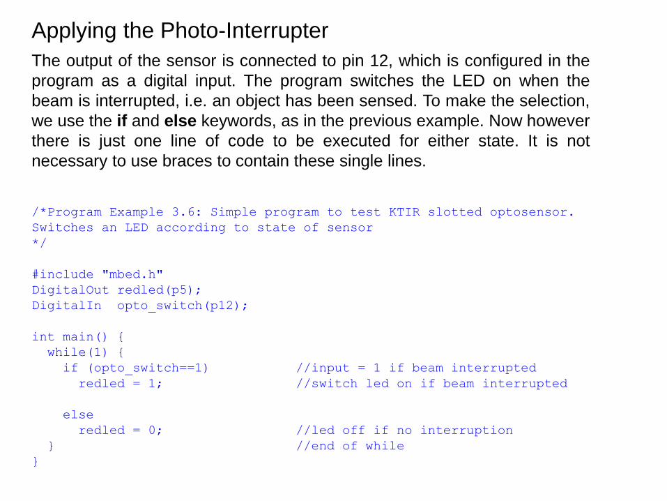
/*Program Example 3.6: Simple program to test KTIR slotted optosensor.
Switches an LED according to state of sensor
*/
#include "mbed.h"
DigitalOut redled(p5);
DigitalIn opto_switch(p12);
int main() {
while(1) {
if (opto_switch==1) //input = 1 if beam interrupted
redled = 1; //switch led on if beam interrupted
else
redled = 0; //led off if no interruption
} //end of while
}
Applying the Photo-Interrupter
The output of the sensor is connected to pin 12, which is configured in the
program as a digital input. The program switches the LED on when the
beam is interrupted, i.e. an object has been sensed. To make the selection,
we use the if and else keywords, as in the previous example. Now however
there is just one line of code to be executed for either state. It is not
necessary to use braces to contain these single lines.

Seven-Segment Displays
The seven-segment display is a versatile configuration. By lighting different
combinations of the seven segments, all numerical digits can be displayed,
as well as a surprising number of alphabetic characters. A decimal point is
usually included, as shown. This means that there are eight LEDs in the
display, needing 16 connections. To simplify matters, either all LED anodes
(“common anode”) are connected together, or all LED cathodes (“common
cathode”).

Driving the Display
A small seven-segment display can be driven directly from a microcontroller. In
the case of common cathode, the cathode is connected to ground, and each
segment is connected to a port pin. If the segments are connected in this
sequence to form a byte,
(MSB) DP g f e d c b a (LSB)
then the values shown in the Table apply. For example, if 0 is to be displayed,
then all outer segments, i.e. abcdef must be lit, with the corresponding bits
from the microcontroller set to 1.

Mbed Connected to a Common Cathode Display
The mbed runs from a 3.3 V supply. Each
display LED requires around 1.8 V across it
in order to light. This is within the mbed
capability. If there were two LEDs in series
in each segment however, the mbed would
barely be able to switch them into
conduction.
The internal resistance of the mbed
output pins can be shown to be very
approximately 100 W.
Calculating as shown, the current per
diode is around 15 mA, a reasonable
value for an LED.
Questions from the Quiz
6. What is the current taken by the display in the previous slide, when the
digit 3 is showing?
7. If in the previous slide a segment current of approximately 4 mA was
required, what value of resistor would need to be introduced in series with
each segment?

/*Program Example 3.7: Simple demonstration of 7-segment display. Display
digits 0, 1, 2, 3 in turn.
*/
#include "mbed.h"
BusOut display(p5,p6,p7,p8,p9,p10,p11,p12); // segments a,b,c,d,e,f,g,dp
int main() {
while(1) {
for(int i=0; i<4; i++) {
switch (i){
case 0: display = 0x3F; break; //display 0
case 1: display = 0x06; break; //display 1
case 2: display = 0x5B; break;
case 3: display = 0x4F; break;
} //end of switch
wait(0.2);
} //end of for
} //end of while
} //end of main
Driving the Display, and some new Programming Features
C code
feature Note the use of the for( ) loop, an alternative to while( ) for
creating conditional loops. Using switch( ) allows selection of one
of a range of options within a list, identified with the case keyword.
Each option is terminated with break.

Switching Larger DC loads
The mbed can drive simple DC loads directly with its digital I/O pins. If it’s
necessary to drive a load - say a motor - which needs more current than an
mbed port pin can supply, or which needs to run from a higher voltage, then an
interface circuit will be needed.
A good switching transistor for small
DC loads is the ZVN4206A, with main
characteristics shown. An important
value is the maximum VGS threshold
value, shown as 3 V. This means that
the MOSFET will respond, just, to the
3.3V Logic 1 output level of the mbed.
Drain

Switching Inductive Loads
A freewheeling diode is now needed because any inductance with current
flowing in it stores energy in the magnetic field which surrounds it. When
that current is interrupted, in this case by the transistor being switched off,
the energy has to be returned to the circuit. This happens through the diode,
which allows decaying current to continue to circulate.

Switching a DC motor with the mbed
The circuit shown can be applied. Any mbed digital output pin can of course
be used.

• Logic signals, expressed mathematically as 0 or 1, are represented in digital
electronic circuits as voltages. One range of voltages represents 0, another
represents 1.
• The mbed has 26 digital I/O pins, which can be configured either as input or
output.
• LEDs can be driven directly from the mbed digital outputs. They are a useful
means of displaying a logic value, and of contributing to a simple human
interface.
• Electromechanical switches can be connected to provide logic values to
digital inputs.
• Multi-coloured LEDs can be made by enclosing several individual LEDs of
different colors in the same housing. The mbed application board contains
one of these.
• A range of simple opto-sensors have almost digital outputs, and can with care
be connected directly to mbed pins.
• Where the mbed pin cannot provide enough power to drive an electrical load
directly, interface circuits must be used. For simple on/off switching a
transistor is often all that is needed.
Chapter Review