
Chapter 3 DESIGN CONCEPT FOR PRECAST SYSTEMChapter 3 DESIGN CONCEPT FOR PRECAST SYSTEM 3.1...
25
23 Chapter 3 DESIGN CONCEPT FOR PRECAST SYSTEM 3.1 STRUCTURAL CONCEPT Based on considerations of buildability, economy and standardisation of precast components, the structural concept developed consists of: • Conventional foundations comprising footings, raft slab or piles and pile caps. • Cast in-situ first storey, typically reinforced concrete beam and slab system. • Precast concrete load bearing walls. • Precast concrete non-load bearing façade panels. • Precast concrete floor system, either: - Precast concrete beams and precast slabs (reinforced concrete or prestressed) with a composite in-situ topping or Precast concrete walls with precast concrete slab system Figure 3.1 Precast prestressed slabs spanning between walls with composite in-situ topping for 1 st storey
Transcript of Chapter 3 DESIGN CONCEPT FOR PRECAST SYSTEMChapter 3 DESIGN CONCEPT FOR PRECAST SYSTEM 3.1...

23
Chapter 3 DESIGN CONCEPT FOR PRECAST SYSTEM 3.1 STRUCTURAL CONCEPT Based on considerations of buildability, economy and standardisation of precast components, the structural concept developed consists of:
• Conventional foundations comprising footings, raft slab or piles and pile caps. • Cast in-situ first storey, typically reinforced concrete beam and slab system. • Precast concrete load bearing walls. • Precast concrete non-load bearing façade panels. • Precast concrete floor system, either:
- Precast concrete beams and precast slabs (reinforced concrete or prestressed) with a composite in-situ topping or Precast concrete walls with precast concrete slab system
Figure 3.1 Precast prestressed slabs spanning between walls with composite in-situ topping for 1st storey

24
Figure 3.2 Precast prestressed slabs spanning between walls with composite in-situ
topping for 2nd storey
Figure 3.3 Precast prestressed slabs spanning between walls with composite in-situ
topping for 3rd storey

25
Figure 3.4 Precast prestressed slabs spanning between walls with composite in-situ
topping for roof
26
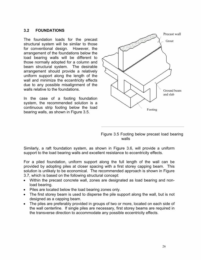
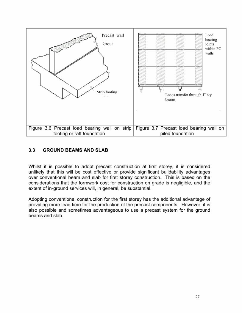
3.2 FOUNDATIONS The foundation loads for the precast structural system will be similar to those for conventional design. However, the arrangement of the foundations below the load bearing walls will be different to those normally adopted for a column and beam structural system. The desirable arrangement should provide a relatively uniform support along the length of the wall and minimize the eccentricity effects due to any possible misalignment of the walls relative to the foundations. In the case of a footing foundation system, the recommended solution is a continuous strip footing below the load bearing walls, as shown in Figure 3.5.
Figure 3.5 Footing below precast load bearing
walls Similarly, a raft foundation system, as shown in Figure 3.6, will provide a uniform support to the load bearing walls and excellent resistance to eccentricity effects.
For a piled foundation, uniform support along the full length of the wall can be provided by adopting piles at closer spacing with a first storey capping beam. This solution is unlikely to be economical. The recommended approach is shown in Figure 3.7, which is based on the following structural concept: • Within the precast concrete wall, zones are designated as load bearing and non-
load bearing. • Piles are located below the load bearing zones only. • The first storey beam is used to disperse the pile support along the wall, but is not
designed as a capping beam. • The piles are preferably provided in groups of two or more, located on each side of
the wall centerline. If single piles are necessary, first storey beams are required in the transverse direction to accommodate any possible eccentricity effects.
Precast wall
Grout
Footing
Ground beam and slab
27
Figure 3.6 Precast load bearing wall on strip footing or raft foundation
Figure 3.7 Precast load bearing wall on piled foundation
3.3 GROUND BEAMS AND SLAB Whilst it is possible to adopt precast construction at first storey, it is considered unlikely that this will be cost effective or provide significant buildability advantages over conventional beam and slab for first storey construction. This is based on the considerations that the formwork cost for construction on grade is negligible, and the extent of in-ground services will, in general, be substantial.
Adopting conventional construction for the first storey has the additional advantage of providing more lead time for the production of the precast components. However, it is also possible and sometimes advantageous to use a precast system for the ground beams and slab.
Strip footing
Grout
Precast wall
Loads transfer through 1st sty beams
Load bearing joints within PC walls

28
3.4 PRECAST LOAD BEARING WALLS Precast load bearing walls provide an economical solution when compared to the conventional column/ beam/ infill wall system. The primary advantages are speed of construction and elimination of wet trades.
To minimise the requirement to lap vertical bars, the walls are recommended to be designed as plain concrete members in accordance with CP65 3.9.4.
In adopting the wall thickness, structural adequacy is not the sole consideration. Other factors to be considered include: • Connection details for supported beams and slabs. • Sound transmission and fire rating. • Joint details at panel-to-panel connections. • Possible future embedded services, which could reduce the concrete area
available. Based on typical layouts and building configurations, a thickness of 180mm is recommended for the precast panels used for party walls.
3.4 a In-fill Terrace Units In the case of in-fill terrace units, it is unlikely to be acceptable to provide a new full wall panel system, since usable area will be sacrificed. In these types of projects, the wall panel is recommended to be modified as shown in Figure 3.8. For this type of arrangement, it is likely that design as a plain concrete member will not be possible and lapping of some vertical bars would be required. A thickness of 180mm is recommended for these panels, to enable consistency and hence economy of the precast production.
Figure 3.8 Precast load bearing wall for in-fill unit
Precast “U” panel support system
Existing party wall for adjacent unit

29
3.4 b Corner Terrace and Semi-Detached Houses For corner terrace and semi-detached units, the external side wall is required to be load bearing. In this case, the panel design will be influenced by factors such as:
• The extent of openings required for windows and doors. • Available load paths for transmission of vertical loads. • Horizontal joint details, which due to waterproofing considerations are likely
to lead to eccentric load transfer. • Connection details for supported beams and slabs. • Joint details at panel to panel connections.
In some cases, plain concrete design may be applicable. However, it may usually be necessary to adopt reinforced concrete design with continuity of vertical bars in these load bearing walls. For these walls, the recommended thickness is 150mm.

30
3.5 PRECAST NON-LOAD BEARING FAÇADE PANELS Typically, the wall panels for the front and rear elevations are non-load bearing façade elements. Support of these panels is achieved by any of the following methods:
• The façade panel is connected to main load bearing walls and is designed to carry its own weight between supports.
• The façade panel is connected to the floor slab or beam, which is then designed to provide support to the wall.
Figure 3.9 Facade panel supported by load bearing external walls These panels will typically be designed for vertical loads due to self weight and an allowance for floor loads, if applicable, in addition to horizontal loads due to external wind pressures. A typical panel thickness of 120mm is proposed on the basis of strength considerations and to accommodate window fixings and profiles around the window perimeter.

31
Façade panels will often require three-dimensional architectural features, such as hoods, sills and ledges. In cases where there is a reasonable degree of repetition, customised moulds can be produced, enabling these features to be economically incorporated into the panels. As an alternative, when repetition is limited, it will be most economical to cast the façade panel flat and subsequently add the features, manufactured separately using materials such as precast concrete, GRC, Aluminium or steel.
3.5 a Location of Joints The location of joints between external wall panels should be selected based on careful consideration of the following factors: • Structural Considerations
External wall panels may be load bearing (e.g. side walls of corner terrace, semi-detached or detached) or non load bearing (e.g. front and rear façade panels). In selecting panel joint locations, it is important to consider the panel stability (i.e. ability to resist horizontal loads such as wind pressure or loads specified in the Building Regulations Fourth Schedule).
• Aesthetics Whilst in general, panel joints are not highly visible, locations should be selected which minimise any potential impact on the external façade aesthetics. In general, vertical joints should align for the full height of the building and would preferably be located symmetrically with respect to adjacent features.
• Panel Weight
The weight of panels will dictate the crane capacity required for installation of the wall panels. Apart from the disadvantage of higher cost, larger capacity cranes may not be able to access the site. For typical conditions, a weight limitation of approximately 4 tonnes is considered likely to be applicable. In general, the panel size should be maximized, leading to increased speed of construction and reduced number of panel joints to be treated.
• Transport Limitations
For transportation purposes, it is necessary to limit one of the panel dimensions to 3.6m. In general, panel heights will be less than 3.6m and panel length is based on weight or other considerations. When the required panel height exceeds 3.6m, the length of panel will be reduced to 3.6m or less. Early planning for site access must be undertaken, particularly when houses are built along Category 5 road.

32
• Internal Crack Control To minimise the risk of cracks appearing at the internal face of wall panel joints, the following considerations are relevant: - If possible, locate panel joints at internal wall intersections, inside service
ducts or wardrobes and at other non-visible locations. - Avoid panel joints towards midspan of floors, where beam or slab
deflections could lead to joint opening. - Avoid long continuous runs of panels, where accumulated shrinkage could
result in joint cracking. 3.5 b Treatment for window openings
An effort has been made to develop a standardised approach for the precast panel profile at window openings. The proposed detail is considered suitable for precasting and can be applied for the majority of projects. Refer to Figure 3.10 and Figure 3.11 for the proposed precast panel profile at window openings. The profile has been developed in consideration of the following:
• A drip was provided to the top and the side to discourage the ingress of water. • The protrusion at the head and jambs is provided for waterproofing and allows
the window frame to be fixed from inside the building; this results in some savings as scaffolding would not be necessary.
• The protrusion allows sufficient space to apply grouting at the joint for water tightness.
• The protrusion protects any sealant from direct exposure to the sun.

33
Figure 3.11 Opening for Window at precast Figure 3.10 Opening for Bay window facade wall
Alum. window extrusion is indicative only

34
3.6 PRECAST FLOOR SYSTEM Two alternate floor systems have been developed for the proposed precast system. In both systems, an in-situ structural topping is adopted, based on the following considerations: • Precast slabs are less thickness and thus reduced weight. • Different composite slab thickness can be achieved, as required by structural
considerations, by varying the topping thickness but keeping the precast thickness constant.
• The topping concrete and reinforcement provide a simple means of tying the floor and wall components together.
• Services are simply provided at site within the topping concrete. Services within the bathroom and toilet floors are generally of significant diameter and required to be laid to fall. In these areas, it is likely that a minimum topping thickness of 85mm would be necessary to incorporate these services. Assuming that the slab soffit is flat, to limit the total slab thickness for the floor adjacent to the bathroom, it is encouraged to limit to only one drop of 50mm at the wet areas. For shower areas, it is recommended to have kerb instead of a second drop to avoid thickening the slab at non-drop area. 3.6 a Floor System Alternate 1 - Prestressed Plank and Half-Slab Floor System This precast floor system (refer to Figure 3.12), comprises prestressed planks spanning between load-bearing walls. Where voids, stairs and other features prevent the slabs from spanning between walls, slabs spanning perpendicularly are provided, supported by the adjacent planks. The merits of this system are as follows: • Floor beams are eliminated, resulting in simpler components and reduced services co-
ordination problems. • Stepping of building line at front and rear are easily accommodated. • Full height window and other facade features can be designed • Can accommodate irregular layouts, with less requirement for false ceilings In this system, the following factors need to be considered: • At roof level, any significant RC gutters will prevent slabs from spanning between walls. • For some floor layouts, alignment of stair openings and voids can prevent slabs from
spanning between walls. • The volume of concrete for this system is likely to be 0 ~ 20% higher than conventional
RC beam and slab.

35
Figure 3.12 Typical floor layout for precast walls with precast slab

36
3.6 b Floor System Alternate 2 - Precast beams and precast slabs
This precast floor system (refer to Figure 3.13) comprises RC half-beams spanning between load bearing walls and half-slabs spanning between beams. This system is similar to conventional RC design in terms of structural support.
However, other factors to be considered for the precast beam and slab floor system are:
• Beam penetrations will often be required for M&E services. These will require
significant co-ordination and are technically difficult for the half beam system. • Beam connections to supporting walls are preferably via wall pockets. The pockets can
become deep when floor levels between adjacent units vary significantly.
Figure 3.13 Typical floor layout for precast walls with precast beams and precast slab

37
3.7 Connection details 3.7 a Treatment of joints for load bearing party walls
Recommended jointing details as shown in Figure 3.14 (Detail 1)
Figure 3.14 Joints at party wall and connection between party walls and facade walls
Figure 3.15 Layout plan for precast wall with prestressed precast planks (with section marking)

38
3.7 b Treatment of Joint for non-load bearing facade panels
For vertical joints, a wet pour of grout / 9mm aggregate mix is provided as a waterproofing backup and to assist with crack control on the internal face.
An important consideration with the proposed details is continuity of sealant. Options are given for façade to party wall, depending on whether party wall is
exposed or hidden. Selection of the appropriate detail will depend on considerations of layout, appearance and whether the adjoining units are staggered horizontally.
Recommended jointing details as shown in Figure 3.16 to Figure 3.22.
Figure 3.16 Plan of connection for long panel of facade walls or end walls
Figure 3.17 Section of water-stop detailing for wall-slab system
Figure 3.18 Section of water-stop detailing for beam-slab system

39
Figure 3.19 Option A - Plan of connection between end wall and facade wall
Figure 3.20 Option A - Plan of connection between party wall and facade wall
Figure 3.21 Option B - Plan of connection between end wall and facade wall
Figure 3.22 Option B - Plan of connection between party wall and facade wall

40
3.7 c Connection details for floor planks
Recommendations on connection are shown below:
Figure 3.23 Section of pour strip for precast slab
Figure 3.24 Section of slab with change in slab thickness
Figure 3.25 Section of pour strip with additional bars for slab support
Figure 3.26 Section of pour strip with top drops for slabs

41
Figure 3.27 Section of slab details to facade walls
Figure 3.28 Section of slab details to party walls
Figure 3.29 Section of slab details to pour strip of party walls
42
3.8 M&E SERVICES
In conventional in-situ construction, M&E services are embedded in the cast-in-situ slab/wall/columns or brick walls. The planning and routing of these M&E services are usually left to the various sub-contractors working quite independently of each other on site. However, co-ordination between the different trades can be lacking and unsatisfactory. This frequently results in situations where M&E services are missed out, wrongly placed or cannot be placed because of inadequate space provisions. As M&E installations can often affect concreting works which are on the critical construction path, project delays and additional costs can occur. Conversely, in a precast construction environment, it is necessary to pre-plan and pre-determine almost all M&E services inside individual precast panels beforehand. This requirement poses a basic change in standard working practice and it can be overwhelming to contractors not accustomed to it or not having enough resources. However, such pre-planning can prevent M&E mistakes, improve quality, reduce delays and reduce costs. 3.8 a Option 1 - Services in Topping In this option, the horizontal services need to be embedded either in the slab topping or the precast plank itself and the vertical element is embedded in the precast wall. Co-ordination work is quite extensive, as all M&E services inside individual precast panels or planks need to be pre-planned and pre-determined beforehand. In particular, the interface between the horizontal and vertical element needs to be co-ordinated to ensure that they coincide exactly. Another consideration is that precast panels are usually thinner than conventional brick and plastered walls. Hence, it is important to ensure that all services are accommodated without affecting the structural integrity of the panel.
In view of the above-mentioned considerations, the following section is a guideline for the proper incorporation of M&E services in a precast project. Technical Details A. Electrical Services • Provide connection ring for ceiling light points at precast plank. Connection of
junction boxes and conduits to be embedded in the slab topping on site with 200mm by 200mm pockets for connection to vertical element.
• Provide cast-in conduit/KO boxes in precast wall panel for switches/wall light, with 200mm by 100mm pockets at top/bottom for switches/wall light points for connection to horizontal element.

43
• Horizontal conduits for power/SCV/telephone to be embedded in slab topping with pockets provided for connection to vertical element.
• Provide appropriate size groove of 40mm depth at precast wall panel for installation of vertical conduits and KO boxes.
• All pockets and grooves to be patched back with structural grout after completion of installation and connection.
B. Plumbing and Sanitary Services • Provide 75mm width by 40mm depth groove for concealed hot & cold water
piping in precast wall panel. • Provide 75mm width by 50mm depth groove for concealed basin/sink waste
vertical pipes in precast wall panel. • Minimum topping of 90mm is required for concealing the horizontal waste
pipes in the topping with a 250mm by 300mm box-out for the floor trap and 150mm by 150mm box-out for floor waste at the bathroom precast plank.
• Horizontal waste pipes to be embedded within the topping together with the floor trap and floor waste and cast together.
• All pockets and grooves at wall panel to be patched back with structural grout after completion of installation and connection.
C. ACMV Services • Provide cast-in condensed drain pipes with insulation in the precast wall panel
with 150Wx300Hx75D mm groove at bottom and 150Wx500Hx75D mm groove at top for connection and refrigerant pipes at fan coil location.
• Provide individual condensate pipes dropper to ground floor for connection to drain or floor trap at ground floor.
• Provide 75Wx25D mm groove at precast plank between fan coil unit and condensate pipes dropper for horizontal condensed pipes to ensure good gradients.
• Horizontal condensed pipes to be embedded within the topping with 200mm by 150mm pocket for connection to vertical element.
• All pockets and grooves at wall panel to be patched back with structural grout after completion of installation and connection
D. M&E Co-ordination Work Pre-planning of all M&E services in the precast plank and wall is critical in ensuring that the horizontal and vertical elements can be joined easily and the installation works can be carried out smoothly. The following provides a guideline for the co-ordination of M&E services in a precast development. • All M&E services routing and installation procedure must be confirmed before
commencement of precast operations.

44
• All precast panels need to be confirmed and individually named to ensure that the location of each panel can be determined correctly during launching.
• Precast Geometry Drawing must be produced by the precaster (including layout plans) and issued to the M&E contractor for him to incorporate the M&E services into the precast panels before commencing precast production.
• Main contractor to incorporate individual services into a combined services geometry drawing for construction.
Figure 3.29 Option 1 - Services laid within the cast in-situ topping over the PC
slab

45
Figure 3.30 Option 1 - Proper co-ordination at interface between horizontal vertical
element
Figure 3.31 Option 1 - Typical elevation and section
46
3.8 b Option 2 – External Tray Instead of embedding all M&E services within the precast panels, this option makes use of an external tray / ring system. There are a number of additional advantages to this system (in comparison to the previous option). Whilst good planning is still essential, the option here reduces the extent and degree of pre-planning required. It will no longer be necessary to plan and ensure that M&E services are properly accommodated within the panels to prevent any adverse impact on structural integrity. Instead, there will be additional flexibilities for changes or additions of M&E services.
Technical Details All M&E services are housed together in an external tray which is mounted on the wall / ceiling surface. Architectural treatment such as a false ceiling or a bulkhead would be used to conceal these services. A typical bulkhead is shown in the attached drawings. In a worse case scenario, a bulkhead of up to 400mm would be needed. This would generally not be an issue as the clear floor height of a typical landed house would be in excess of 3 metres.
Vertical lines generally would have to be pre-planned and concealed in walls. These are facilitated by the use of “pockets” or wider grooves left in the precast panels for connection, such as power points, electrical wirings or pipings for fan-coil unit. The positions of these connecting pockets would have to be pre-determined. Fortunately, in a typical landed housing environment, the positions of these elements are easy to determine and plan for. The pockets would be grouted with appropriate material after the M&E connections have been made on site. The slightly larger size pockets / grooves will cater for site tolerance and ease of connection.
Horizontal lines are installed on top of the precast floor slab at site. These services would be concealed in the concrete topping layer later.

47
Figure 3.32 Option 2 - Using external tray
450
400
200