![[PPT]Chapter 12: Structures & Properties of Ceramicsbohr.winthrop.edu/faculty/mahes/link_to_webpages/courses... · Web viewISSUES TO ADDRESS... • How do the crystal structures of](https://static.fdocuments.in/doc/165x107/5afb4ce17f8b9aac24910e72/pptchapter-12-structures-properties-of-viewissues-to-address-how-do-the.jpg)
CHAPTER 3: Crystal structures and properties
41
ISSUES TO ADDRESS... • How do atoms assemble into solid structures? (for now, focus on metals) • How does the density of a material depend on its structure? • When do material properties vary with the sample (i.e., part) orientation? 1 CHAPTER 3: Crystal structures and properties
Transcript of CHAPTER 3: Crystal structures and properties
ISSUES TO ADDRESS...
• How do atoms assemble into solid structures?(for now, focus on metals)
• How does the density of a material depend onits structure?
• When do material properties vary with thesample (i.e., part) orientation?
1
CHAPTER 3: Crystal structures and properties
2
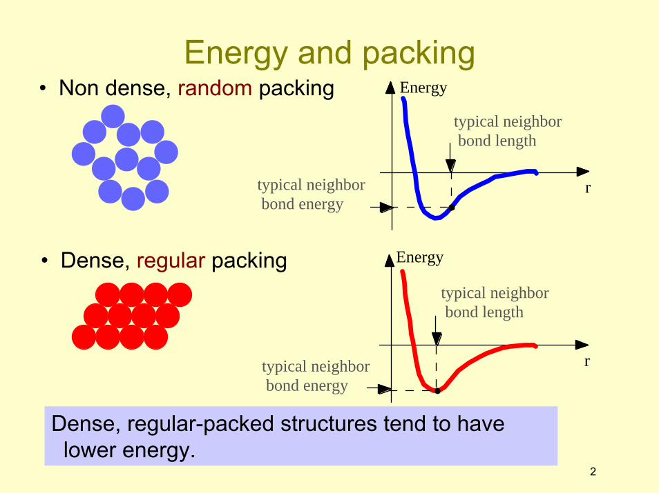
• Non dense, random packing
• Dense, regular packing
Dense, regular-packed structures tend to havelower energy.
Energy
r
typical neighbor bond length
typical neighbor bond energy
Energy
r
typical neighbor bond length
typical neighbor bond energy
Energy and packing
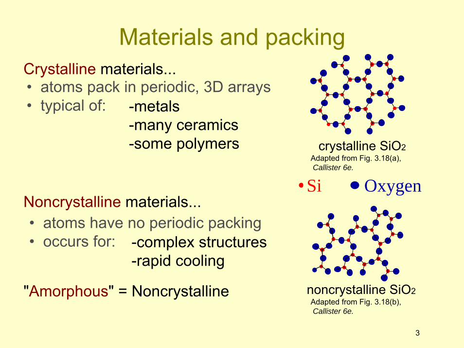
• atoms pack in periodic, 3D arrays• typical of:
Crystalline materials...
-metals-many ceramics-some polymers
3
• atoms have no periodic packing• occurs for:
Noncrystalline materials...
-complex structures-rapid cooling
Si Oxygen
crystalline SiO2Adapted from Fig. 3.18(a),Callister 6e.
noncrystalline SiO2Adapted from Fig. 3.18(b),Callister 6e.
"Amorphous" = Noncrystalline
Materials and packing
4
• tend to be densely packed.• have several reasons for dense packing:
-Typically, only one element is present, so all atomicradii are the same.
-Metallic bonding is not directional.-Nearest neighbor distances tend to be small in
order to lower bond energy.
• have the simplest crystal structures.
We will look at three such structures...
Metallic crystals
5
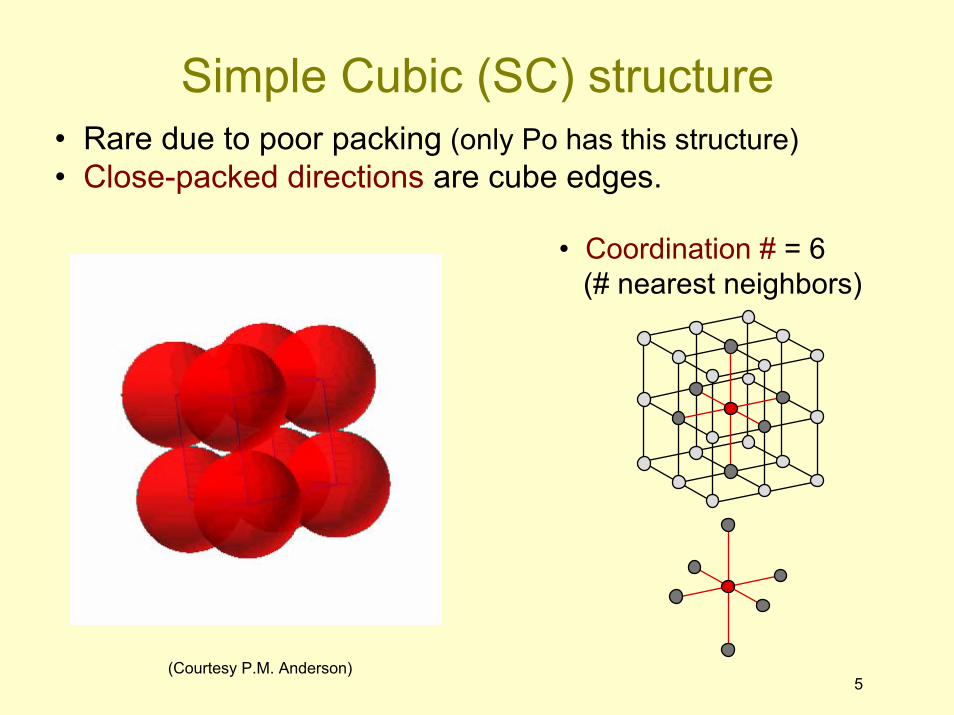
• Rare due to poor packing (only Po has this structure)• Close-packed directions are cube edges.
• Coordination # = 6(# nearest neighbors)
(Courtesy P.M. Anderson)
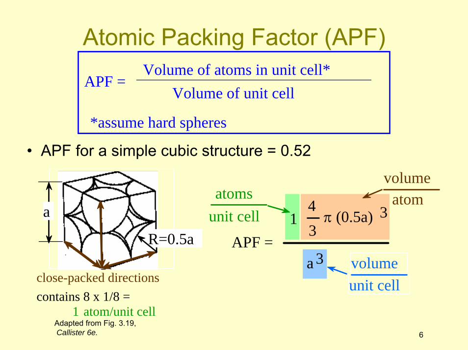
Simple Cubic (SC) structure
6
APF = Volume of atoms in unit cell*
Volume of unit cell
*assume hard spheres
• APF for a simple cubic structure = 0.52
APF = a 3
43
π (0.5a) 31atoms
unit cellatom
volume
unit cellvolume
close-packed directions
a
R=0.5a
contains 8 x 1/8 = 1 atom/unit cell
Adapted from Fig. 3.19,Callister 6e.
Atomic Packing Factor (APF)
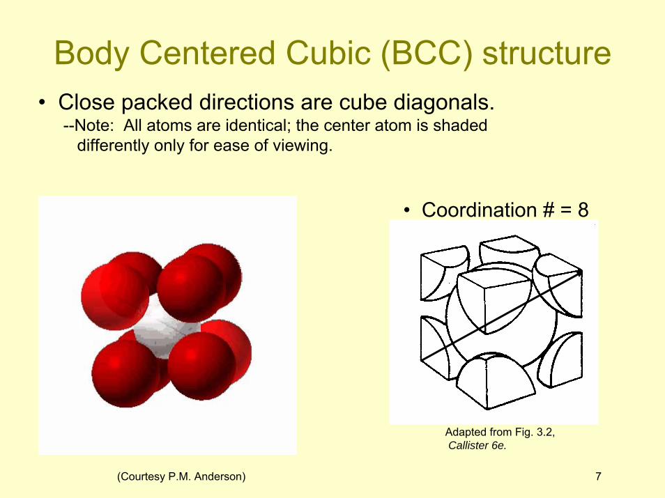
• Coordination # = 8
7
Adapted from Fig. 3.2,Callister 6e.
(Courtesy P.M. Anderson)
• Close packed directions are cube diagonals.--Note: All atoms are identical; the center atom is shaded
differently only for ease of viewing.
Body Centered Cubic (BCC) structure
aR
8
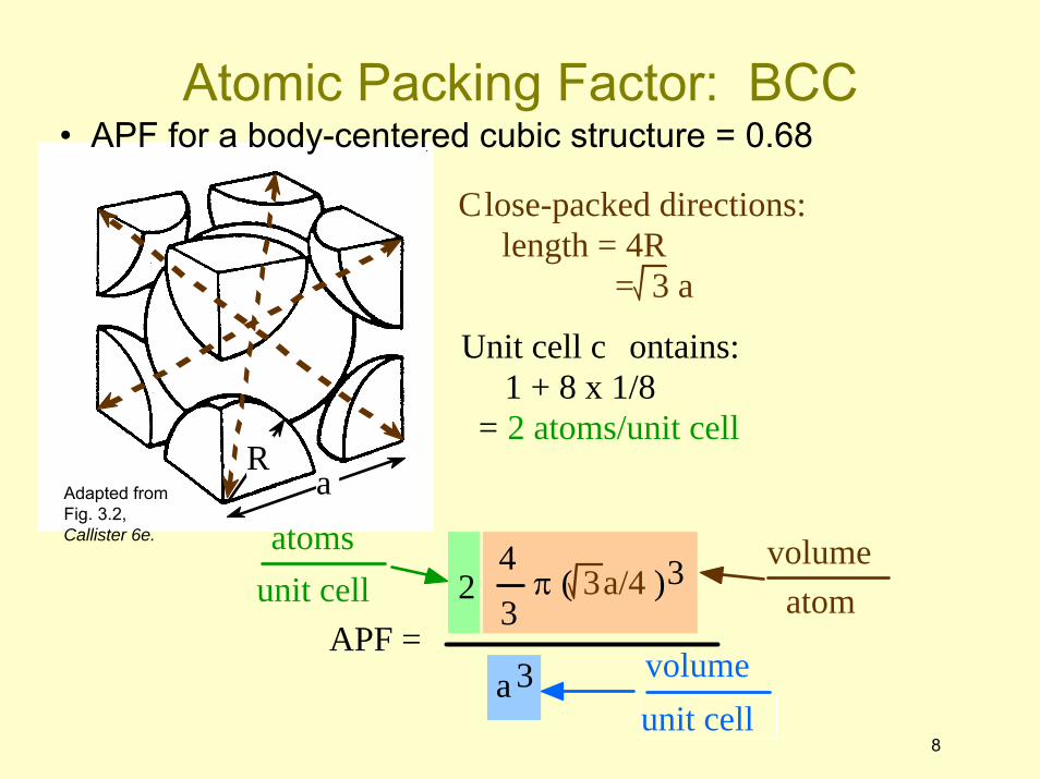
• APF for a body-centered cubic structure = 0.68
Close-packed directions: length = 4R
= 3 a
Unit cell c ontains: 1 + 8 x 1/8 = 2 atoms/unit cell
Adapted fromFig. 3.2,Callister 6e.
Atomic Packing Factor: BCC
APF = a 3
43
π ( 3a/4 )32atoms
unit cell atomvolume
unit cellvolume
9
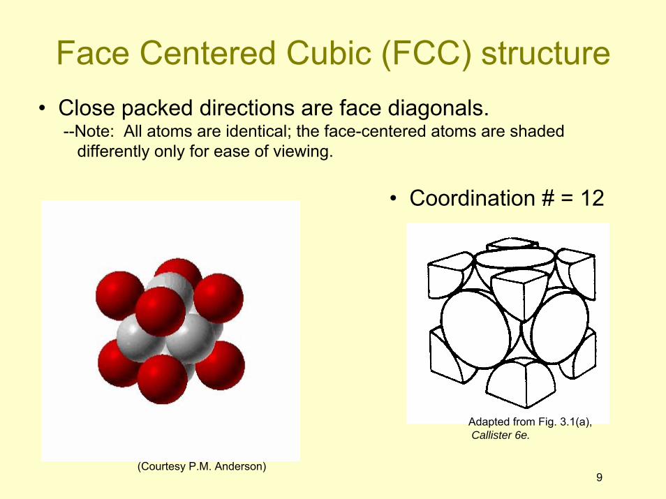
• Coordination # = 12
Adapted from Fig. 3.1(a),Callister 6e.
(Courtesy P.M. Anderson)
• Close packed directions are face diagonals.--Note: All atoms are identical; the face-centered atoms are shaded
differently only for ease of viewing.
Face Centered Cubic (FCC) structure
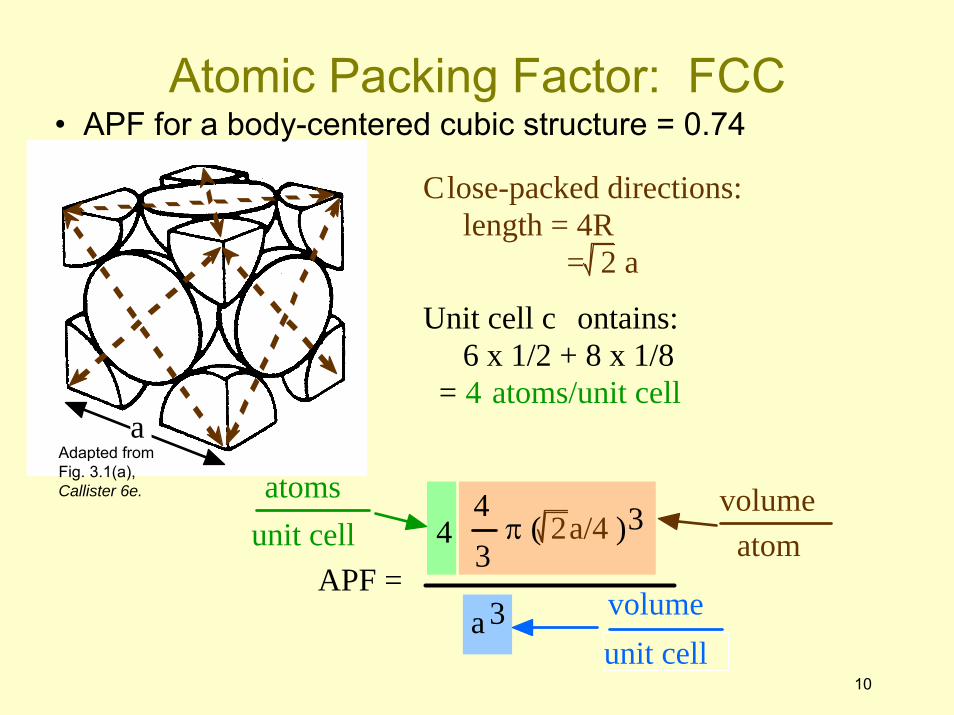
APF = a 3
43
π ( 2a/4 )34atoms
unit cell atomvolume
unit cellvolume
Unit cell c ontains: 6 x 1/2 + 8 x 1/8 = 4 atoms/unit cell
a
10
• APF for a body-centered cubic structure = 0.74
Close-packed directions: length = 4R
= 2 a
Adapted fromFig. 3.1(a),Callister 6e.
Atomic Packing Factor: FCC
11
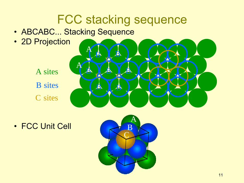
• ABCABC... Stacking Sequence• 2D Projection
A sites
B sitesC sites
B B
B
BB
B BC C
CA
A
• FCC Unit CellA
BC
FCC stacking sequence
12
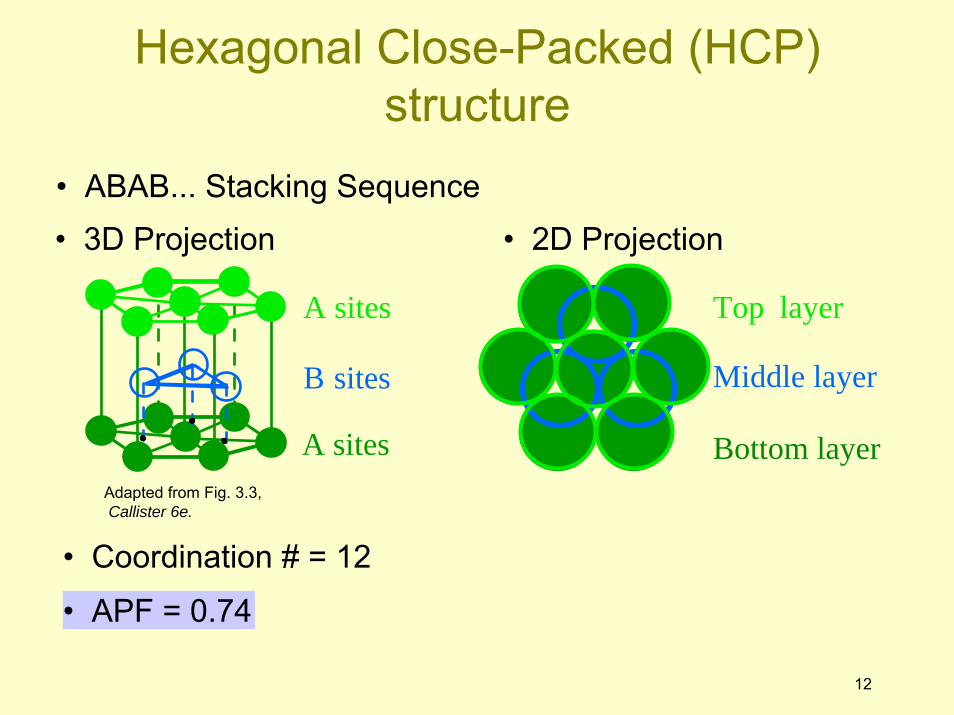
• Coordination # = 12
• ABAB... Stacking Sequence
• APF = 0.74
• 3D Projection • 2D Projection
A sites
B sites
A sites Bottom layer
Middle layer
Top layer
Adapted from Fig. 3.3,Callister 6e.
Hexagonal Close-Packed (HCP) structure
14
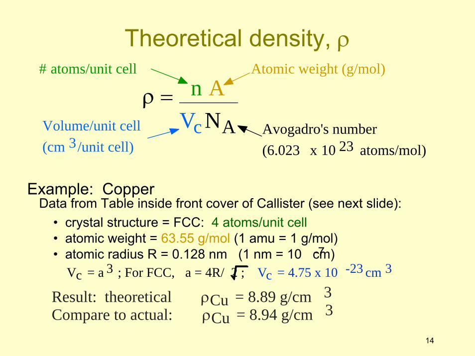
Example: Copper
ρ = n AVc NA
# atoms/unit cell Atomic weight (g/mol)
Volume/unit cell (cm 3/unit cell)
Avogadro's number (6.023 x 10 23 atoms/mol)
Data from Table inside front cover of Callister (see next slide):• crystal structure = FCC: 4 atoms/unit cell• atomic weight = 63.55 g/mol (1 amu = 1 g/mol)• atomic radius R = 0.128 nm (1 nm = 10 cm)-7
Vc = a 3 ; For FCC, a = 4R/ 2 ; Vc = 4.75 x 10 -23 cm 3
Compare to actual: ρCu = 8.94 g/cm 3Result: theoretical ρCu = 8.89 g/cm 3
Theoretical density, ρ
15
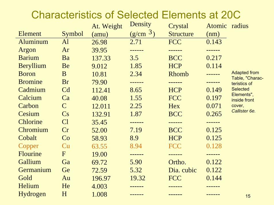
Element Aluminum Argon Barium Beryllium Boron Bromine Cadmium Calcium Carbon Cesium Chlorine Chromium Cobalt Copper Flourine Gallium Germanium Gold Helium Hydrogen
Symbol Al Ar Ba Be B Br Cd Ca C Cs Cl Cr Co Cu F Ga Ge Au He H
At. Weight (amu) 26.98 39.95 137.33 9.012 10.81 79.90 112.41 40.08 12.011 132.91 35.45 52.00 58.93 63.55 19.00 69.72 72.59 196.97 4.003 1.008
Atomic radius (nm) 0.143 ------ 0.217 0.114 ------ ------ 0.149 0.197 0.071 0.265 ------ 0.125 0.125 0.128 ------ 0.122 0.122 0.144 ------ ------
Density (g/cm 3) 2.71 ------ 3.5 1.85 2.34 ------ 8.65 1.55 2.25 1.87 ------ 7.19 8.9 8.94 ------ 5.90 5.32 19.32 ------ ------
Crystal Structure FCC ------ BCC HCP Rhomb ------ HCP FCC Hex BCC ------ BCC HCP FCC ------ Ortho. Dia. cubic FCC ------ ------
Adapted fromTable, "Charac-teristics ofSelectedElements",inside frontcover,Callister 6e.
Characteristics of Selected Elements at 20C
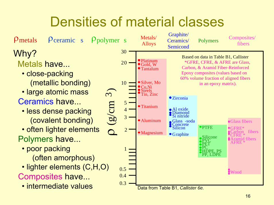
ρmetals � ρceramic s � ρpolymer s
16
ρ (g
/cm
3 )
Graphite/ Ceramics/ Semicond
Metals/ Alloys
Composites/ fibersPolymers
1
2
20
30Based on data in Table B1, Callister
*GFRE, CFRE, & AFRE are Glass, Carbon, & Aramid Fiber-Reinforced Epoxy composites (values based on 60% volume fraction of aligned fibers
in an epoxy matrix). 10
3 4 5
0.3 0.4 0.5
Magnesium
Aluminum
Steels
Titanium
Cu,Ni Tin, Zinc
Silver, Mo
Tantalum Gold, W Platinum
Graphite Silicon Glass -soda Concrete
Si nitride Diamond Al oxide
Zirconia
HDPE, PS PP, LDPE PC
PTFE
PET PVC Silicone
Wood
AFRE * CFRE * GFRE* Glass fibers
Carbon fibers Aramid fibers
Why?Metals have...• close-packing
(metallic bonding)• large atomic mass
Ceramics have...• less dense packing
(covalent bonding)• often lighter elements
Polymers have...• poor packing
(often amorphous)• lighter elements (C,H,O)
Composites have...• intermediate values Data from Table B1, Callister 6e.
Densities of material classes
18
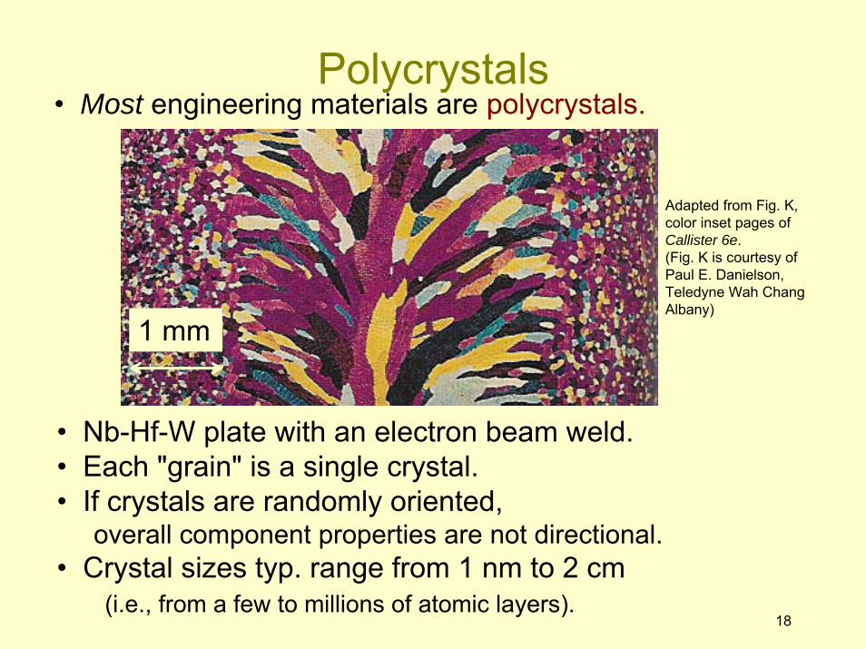
• Most engineering materials are polycrystals.
• Nb-Hf-W plate with an electron beam weld.• Each "grain" is a single crystal.• If crystals are randomly oriented,
overall component properties are not directional.• Crystal sizes typ. range from 1 nm to 2 cm
(i.e., from a few to millions of atomic layers).
Adapted from Fig. K, color inset pages of Callister 6e.(Fig. K is courtesy of Paul E. Danielson, Teledyne Wah Chang Albany)
1 mm
Polycrystals
19
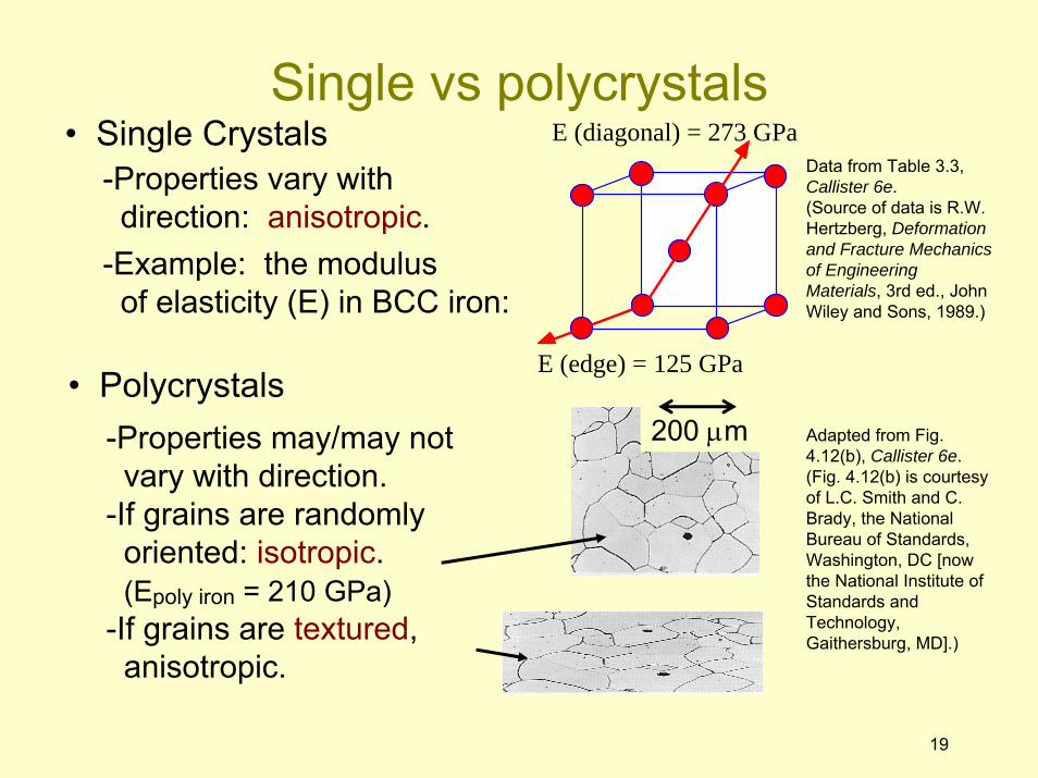
• Single Crystals-Properties vary with
direction: anisotropic.-Example: the modulus
of elasticity (E) in BCC iron:
• Polycrystals-Properties may/may not
vary with direction.-If grains are randomly
oriented: isotropic.(Epoly iron = 210 GPa)
-If grains are textured,anisotropic.
E (diagonal) = 273 GPa
E (edge) = 125 GPa
200 μm
Data from Table 3.3, Callister 6e.(Source of data is R.W. Hertzberg, Deformation and Fracture Mechanics of Engineering Materials, 3rd ed., John Wiley and Sons, 1989.)
Adapted from Fig. 4.12(b), Callister 6e.(Fig. 4.12(b) is courtesy of L.C. Smith and C. Brady, the National Bureau of Standards, Washington, DC [now the National Institute of Standards and Technology, Gaithersburg, MD].)
Single vs polycrystals
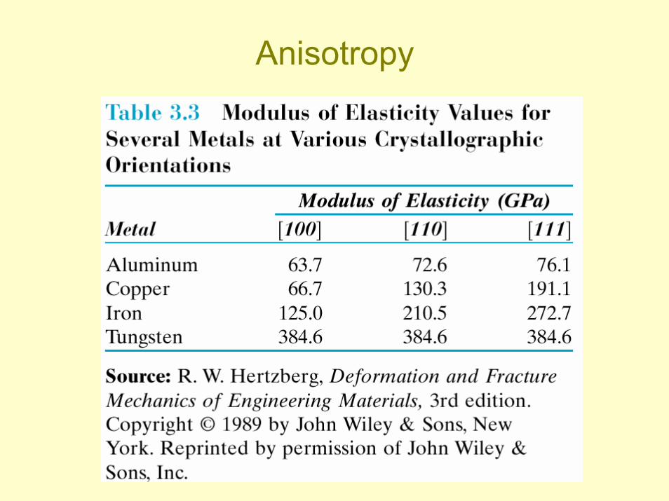
Anisotropy
22
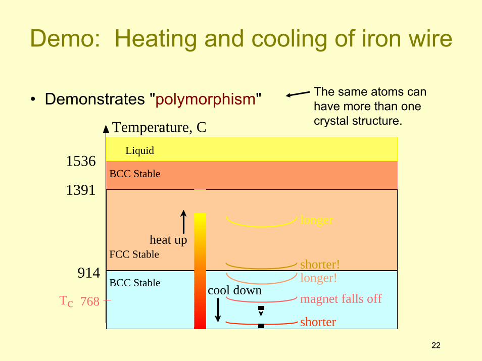
• Demonstrates "polymorphism" The same atoms can have more than one crystal structure.
Demo: Heating and cooling of iron wire
Temperature, C
BCC Stable
FCC Stable
914
1391
1536
shorter
longer!shorter!
longer
Tc 768 magnet falls off
BCC Stable
Liquid
heat up
cool down
ISSUES TO ADDRESS...• Structures of ceramic materials:
How do they differ from that of metals?
1
CHAPTER 12: Structure of ceramics
2
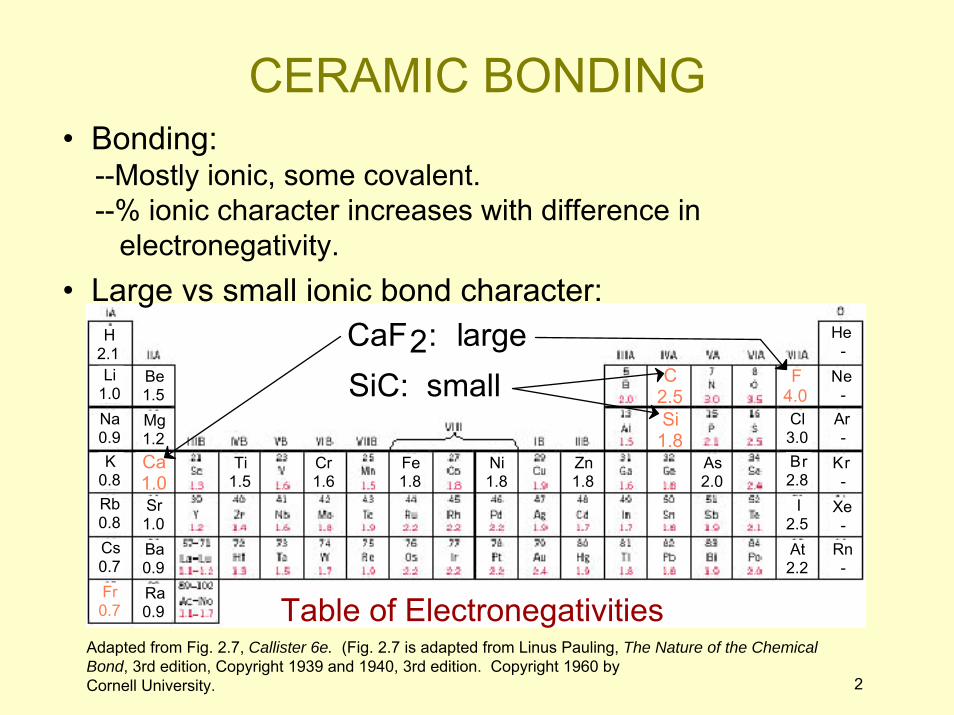
• Bonding:--Mostly ionic, some covalent.--% ionic character increases with difference in
electronegativity.
He -
Ne -
Ar -
Kr -
Xe -
Rn -
Cl 3.0Br 2.8
I 2.5At 2.2
Li 1.0Na 0.9K
0.8Rb 0.8Cs 0.7Fr 0.7
H 2.1
Be 1.5Mg 1.2
Sr 1.0Ba 0.9Ra 0.9
Ti 1.5
Cr 1.6
Fe 1.8
Ni 1.8
Zn 1.8
As 2.0
C 2.5Si
1.8
F 4.0
Ca 1.0
Table of Electronegativities
CaF2: largeSiC: small
Adapted from Fig. 2.7, Callister 6e. (Fig. 2.7 is adapted from Linus Pauling, The Nature of the Chemical Bond, 3rd edition, Copyright 1939 and 1940, 3rd edition. Copyright 1960 byCornell University.
• Large vs small ionic bond character:
CERAMIC BONDING
3
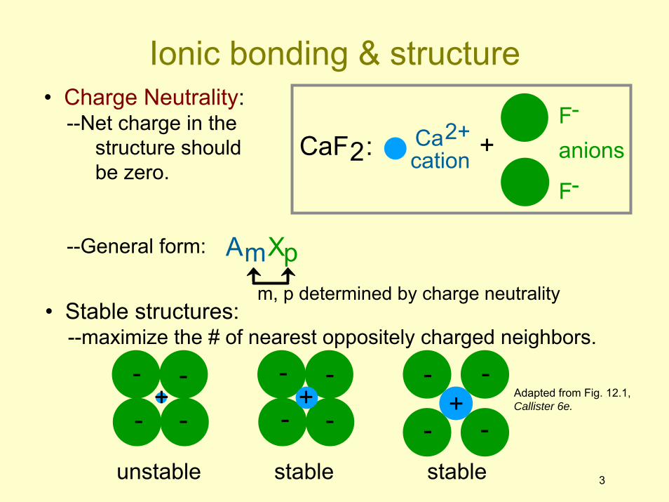
• Charge Neutrality:--Net charge in the
structure shouldbe zero.
--General form: AmXpm, p determined by charge neutrality
• Stable structures:--maximize the # of nearest oppositely charged neighbors.
Adapted from Fig. 12.1, Callister 6e.
- -
- -+
unstable
- -
- -+
stable
- -
- -+
stable
CaF2: Ca2+cation
F-
F-
anions+
Ionic bonding & structure
4
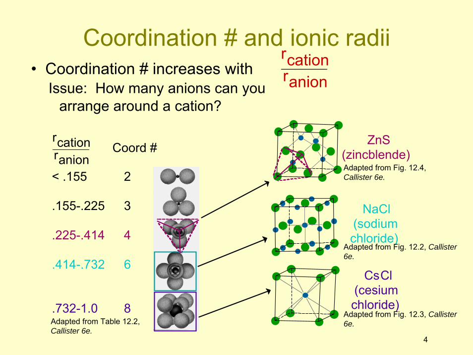
• Coordination # increases withIssue: How many anions can you
arrange around a cation?
rcationranion
rcationranion
Coord #
< .155 .155-.225 .225-.414 .414-.732 .732-1.0
ZnS (zincblende)
NaCl (sodium chloride)
CsCl (cesium chloride)
2 3 4 6 8
Adapted from Table 12.2, Callister 6e.
Adapted from Fig. 12.2, Callister 6e.
Adapted from Fig. 12.3, Callister 6e.
Adapted from Fig. 12.4, Callister 6e.
Coordination # and ionic radii
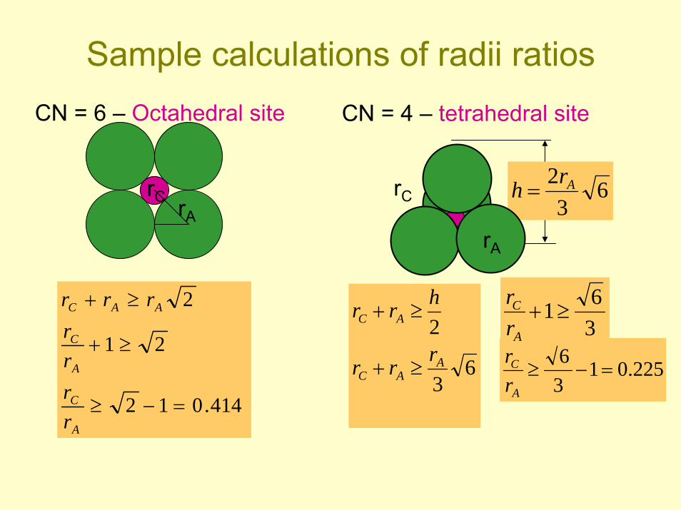
Sample calculations of radii ratios
rC rA
414.012
21
2
=−≥
≥+
≥+
A
C
A
C
AAC
rrrr
rrr
63
2A
AC
AC
rrr
hrr
≥+
≥+
225.0136
=−≥A
C
rr
361≥+
A
C
rr
CN = 4 – tetrahedral siteCN = 6 – Octahedral site
rC
rA
63
2 Arh =
rA
13
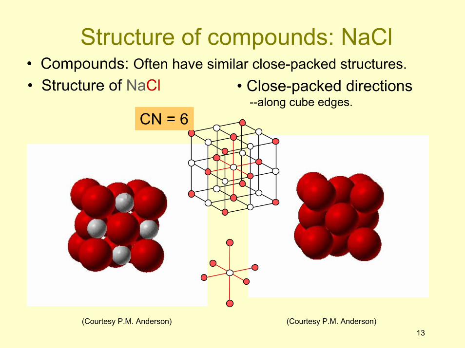
• Compounds: Often have similar close-packed structures.• Close-packed directions
--along cube edges.• Structure of NaCl
(Courtesy P.M. Anderson) (Courtesy P.M. Anderson)
Structure of compounds: NaCl
CN = 6
5
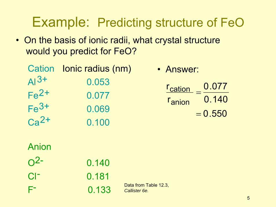
• On the basis of ionic radii, what crystal structurewould you predict for FeO?
Cation Al3+ Fe2+ Fe3+ Ca2+ Anion O2- Cl- F-
Ionic radius (nm) 0.053 0.077 0.069 0.100
0.140 0.181 0.133
• Answer:
rcationranion
=0.0770.140
= 0.550
Data from Table 12.3, Callister 6e.
Example: Predicting structure of FeO
5
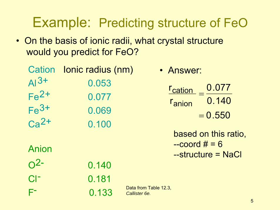
Cation Al3+ Fe2+ Fe3+ Ca2+ Anion O2- Cl- F-
Ionic radius (nm) 0.053 0.077 0.069 0.100
0.140 0.181 0.133
• Answer:
rcationranion
• On the basis of ionic radii, what crystal structurewould you predict for FeO?
=0.0770.140
= 0.550
based on this ratio,--coord # = 6--structure = NaCl
Data from Table 12.3, Callister 6e.
Example: Predicting structure of FeO
6
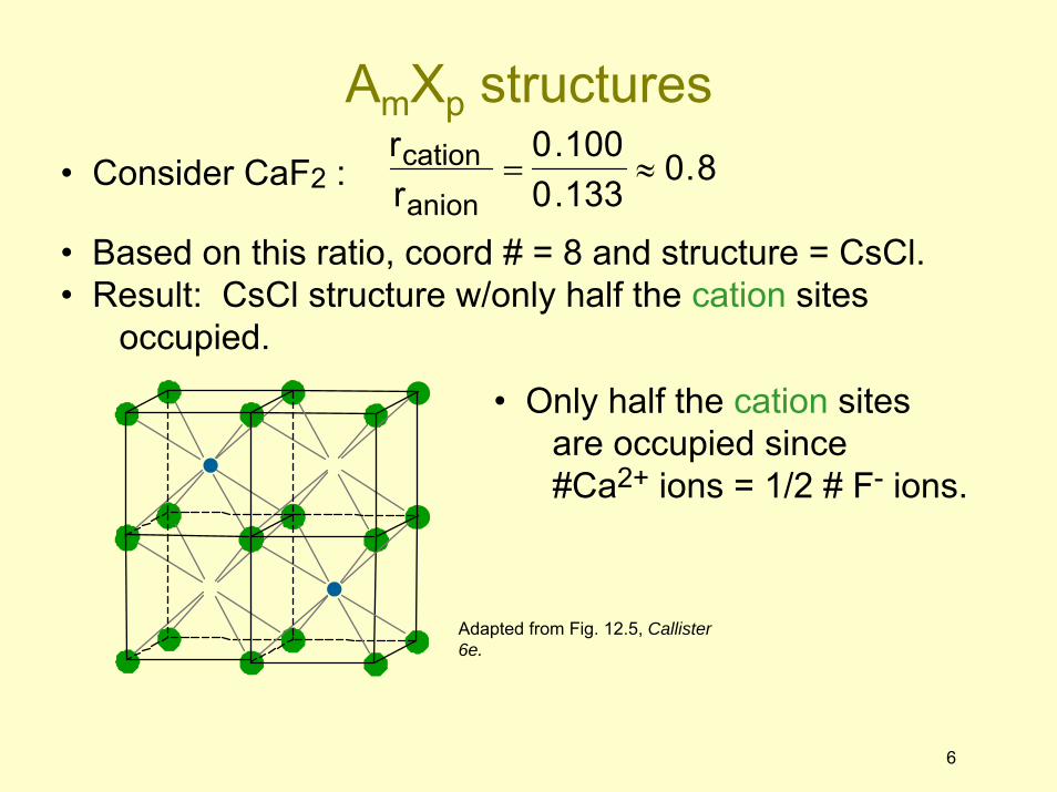
• Consider CaF2 :
rcationranion
=0.1000.133
≈ 0.8
• Based on this ratio, coord # = 8 and structure = CsCl. • Result: CsCl structure w/only half the cation sites
occupied.
• Only half the cation sitesare occupied since#Ca2+ ions = 1/2 # F- ions.
Adapted from Fig. 12.5, Callister 6e.
AmXp structures
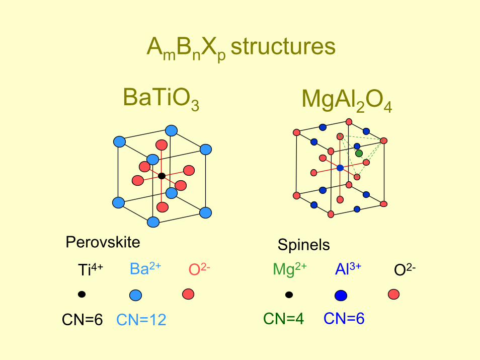
AmBnXp structures
Ti4+ O2-Ba2+ Mg2+ Al3+ O2-
BaTiO3 MgAl2O4
CN=6 CN=12 CN=6CN=4
Perovskite Spinels
• Atoms may assemble into crystalline oramorphous structures
• We can predict the density of a material,provided we know the atomic weight, atomicradius, and crystal geometry (e.g., FCC,BCC, HCP)
• Different structures of the same material are called polymorphs; the material is said to displaypolymorphism
• Material properties generally vary with singlecrystal orientation (i.e., they are anisotropic),but properties are generally non-directional(i.e., they are isotropic) in polycrystals withrandomly oriented grains
23
Summary
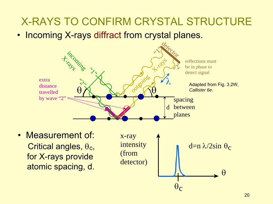
d=n λ/2sin θcx-ray intensity (from detector)
θ
θc20
• Incoming X-rays diffract from crystal planes.
• Measurement of:Critical angles, θc,for X-rays provideatomic spacing, d.
Adapted from Fig. 3.2W, Callister 6e.
X-RAYS TO CONFIRM CRYSTAL STRUCTURE
reflections must be in phase to detect signal
spacing between planes
d
incoming
X-rays
outgo
ing X
-rays
detector
θλ
θextra distance travelled by wave “2”
“1”
“2”
“1”
“2”
Crystallographic directions and planes
Objectives
• To be able to sketch directions corresponding to indices or vice versa in a cubic crystal system
• Specify Miller indices for planes drawn into a unit cell
• Compute planar and linear densities
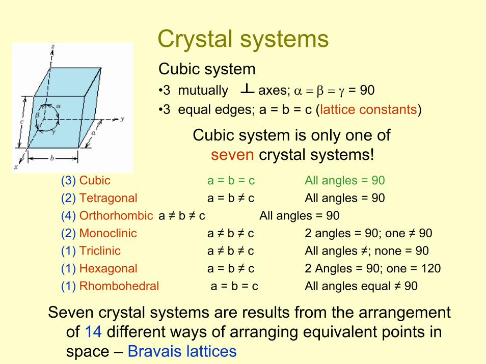
Crystal systems
Cubic system is only one of seven crystal systems!
Cubic system•3 mutually axes; α = β = γ = 90•3 equal edges; a = b = c (lattice constants)
(3) Cubic a = b = c All angles = 90(2) Tetragonal a = b ≠ c All angles = 90(4) Orthorhombic a ≠ b ≠ c All angles = 90(2) Monoclinic a ≠ b ≠ c 2 angles = 90; one ≠ 90(1) Triclinic a ≠ b ≠ c All angles ≠; none = 90(1) Hexagonal a = b ≠ c 2 Angles = 90; one = 120(1) Rhombohedral a = b = c All angles equal ≠ 90
Seven crystal systems are results from the arrangement of 14 different ways of arranging equivalent points in space – Bravais lattices
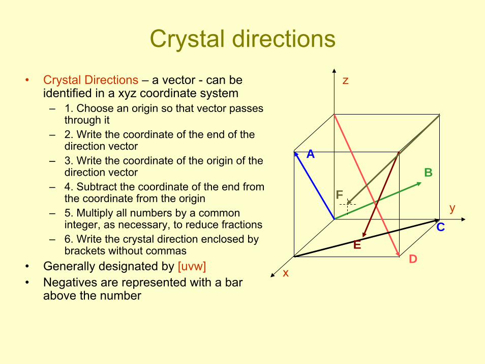
Crystal directions• Crystal Directions – a vector - can be
identified in a xyz coordinate system – 1. Choose an origin so that vector passes
through it– 2. Write the coordinate of the end of the
direction vector – 3. Write the coordinate of the origin of the
direction vector– 4. Subtract the coordinate of the end from
the coordinate from the origin – 5. Multiply all numbers by a common
integer, as necessary, to reduce fractions– 6. Write the crystal direction enclosed by
brackets without commas• Generally designated by [uvw]• Negatives are represented with a bar
above the number
x
z
y
B
D
A
CE
F
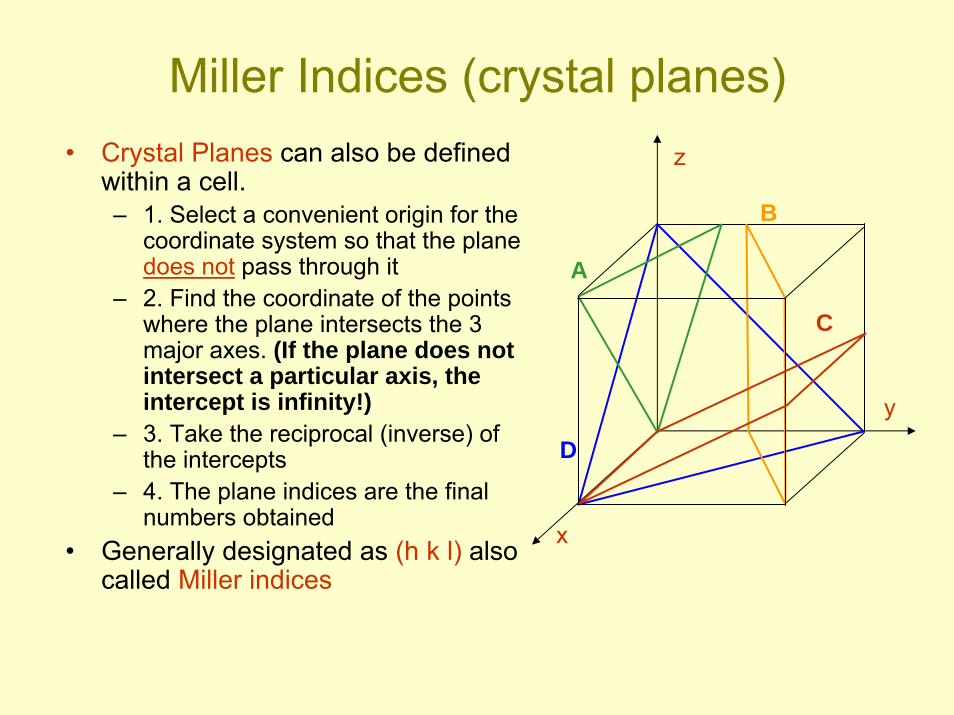
Miller Indices (crystal planes)• Crystal Planes can also be defined
within a cell.– 1. Select a convenient origin for the
coordinate system so that the plane does not pass through it
– 2. Find the coordinate of the points where the plane intersects the 3 major axes. (If the plane does not intersect a particular axis, the intercept is infinity!)
– 3. Take the reciprocal (inverse) of the intercepts
– 4. The plane indices are the final numbers obtained
• Generally designated as (h k l) also called Miller indices
x
z
y
A
B
D
C
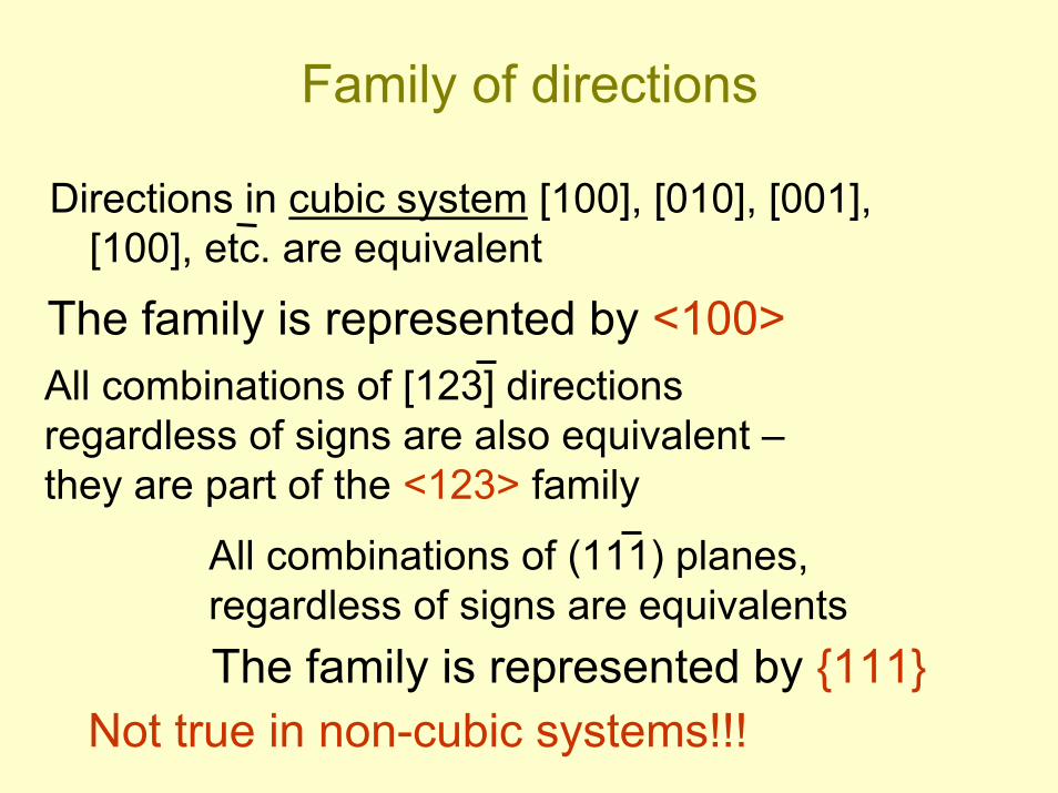
Family of directions
Directions in cubic system [100], [010], [001], [100], etc. are equivalent
The family is represented by <100>All combinations of [123] directions regardless of signs are also equivalent –they are part of the <123> family
Not true in non-cubic systems!!!
All combinations of (111) planes, regardless of signs are equivalentsThe family is represented by {111}
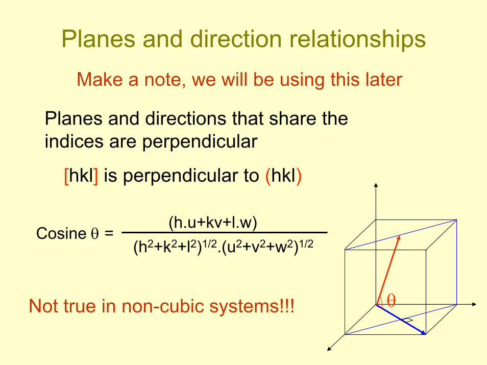
Planes and direction relationships
Planes and directions that share the indices are perpendicular
[hkl] is perpendicular to (hkl)
θ
Cosine θ =(h.u+kv+l.w)
(h2+k2+l2)1/2.(u2+v2+w2)1/2
Not true in non-cubic systems!!!
Make a note, we will be using this later
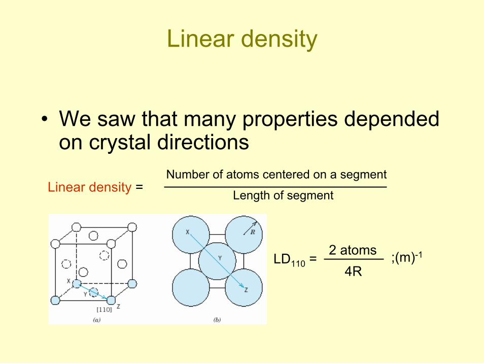
Linear density
• We saw that many properties depended on crystal directions
Number of atoms centered on a segment
Length of segmentLinear density =
LD110 = 2 atoms4R
;(m)-1
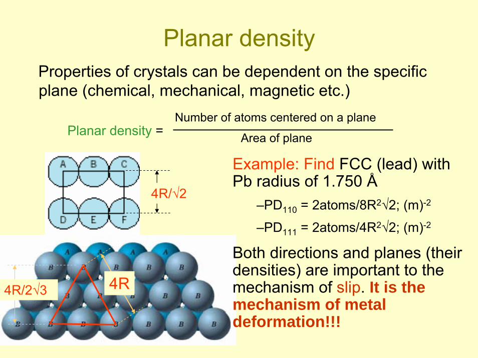
Planar densityProperties of crystals can be dependent on the specific plane (chemical, mechanical, magnetic etc.)
Number of atoms centered on a plane
Area of planePlanar density =
4R
4R/√2
Example: Find FCC (lead) with Pb radius of 1.750 Å
–PD110 = 2atoms/8R2√2; (m)-2
–PD111 = 2atoms/4R2√2; (m)-2
Both directions and planes (their densities) are important to the mechanism of slip. It is the mechanism of metal deformation!!!
4R/2√3
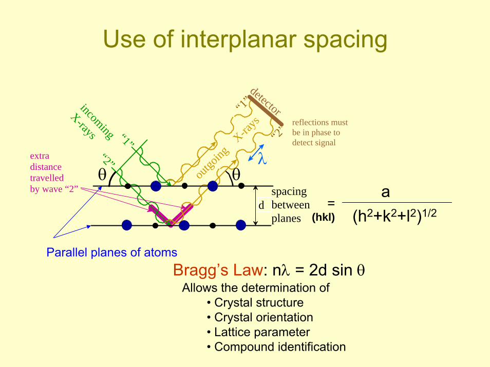
Use of interplanar spacing
=
reflections must be in phase to detect signal
spacing between planes
d
incoming
X-rays
outgo
ing X
-rays
detector
θλ
θextra distance travelled by wave “2”
“1”
“2”
“1”
“2”
a(h2+k2+l2)1/2(hkl)
Bragg’s Law: nλ = 2d sin θParallel planes of atoms
Allows the determination of • Crystal structure• Crystal orientation• Lattice parameter• Compound identification
Reading: All of Chapter 3
Core Problems: due today 2:17, 20, 22; 3:1, 13; 12: 1, 5, 25
Self-help Problems: Examples problems in text
0
ANNOUNCEMENTS


![Synthesis, crystal structures and properties of carbazole-based … · 2021. 1. 4. · 11 Synthesis, crystal structures and properties of carbazole-based [6]helicenes fused with an](https://static.fdocuments.in/doc/165x107/60fee8ef13348044ac53521d/synthesis-crystal-structures-and-properties-of-carbazole-based-2021-1-4-11.jpg)

