Chapter 3 Boolean Algebra and Logic Gate. Basic Operations of Boolean Algebra Boolean algebra –...
25
Chapter 3 Boolean Algebra and Logic Gate
-
date post
19-Dec-2015 -
Category
Documents
-
view
256 -
download
3
Transcript of Chapter 3 Boolean Algebra and Logic Gate. Basic Operations of Boolean Algebra Boolean algebra –...
Chapter 3
Boolean Algebra and Logic Gate
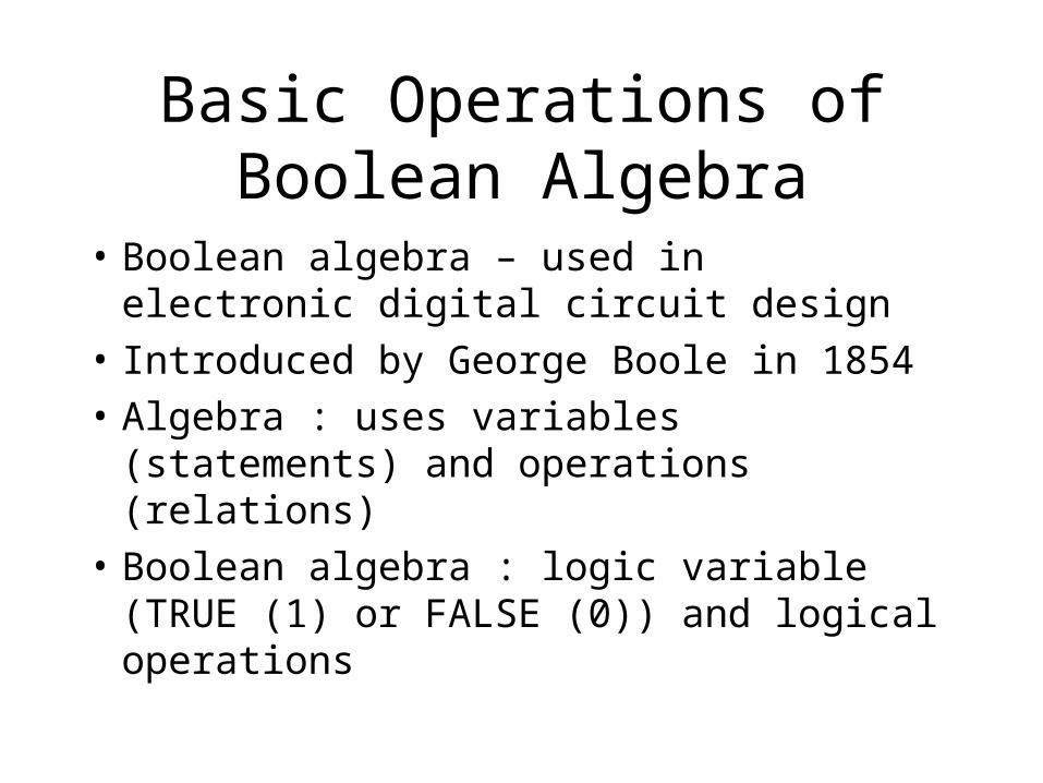
Basic Operations of Boolean Algebra
• Boolean algebra – used in electronic digital circuit design
• Introduced by George Boole in 1854
• Algebra : uses variables (statements) and operations (relations)
• Boolean algebra : logic variable (TRUE (1) or FALSE (0)) and logical operations
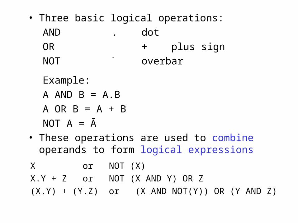
• Three basic logical operations:
AND . dot
OR + plus sign
NOT ¯ overbar
Example:
A AND B = A.B
A OR B = A + B
NOT A = Ā
• These operations are used to combine operands to form logical expressions
X or NOT (X)
X.Y + Z or NOT (X AND Y) OR Z
(X.Y) + (Y.Z) or (X AND NOT(Y)) OR (Y AND Z)
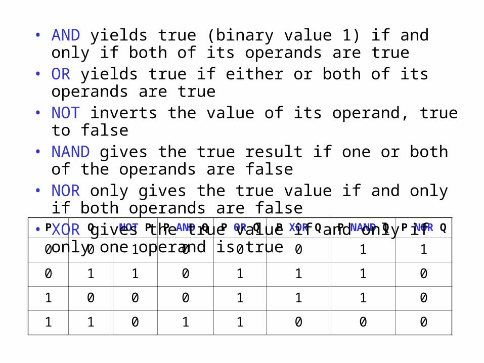
P Q NOT P P AND Q P OR Q P XOR Q P NAND Q P NOR Q
0 0 1 0 0 0 1 1
0 1 1 0 1 1 1 0
1 0 0 0 1 1 1 0
1 1 0 1 1 0 0 0
• AND yields true (binary value 1) if and only if both of its operands are true
• OR yields true if either or both of its operands are true
• NOT inverts the value of its operand, true to false• NAND gives the true result if one or both of the
operands are false• NOR only gives the true value if and only if both
operands are false• XOR gives the true value if and only if only one
operand is true
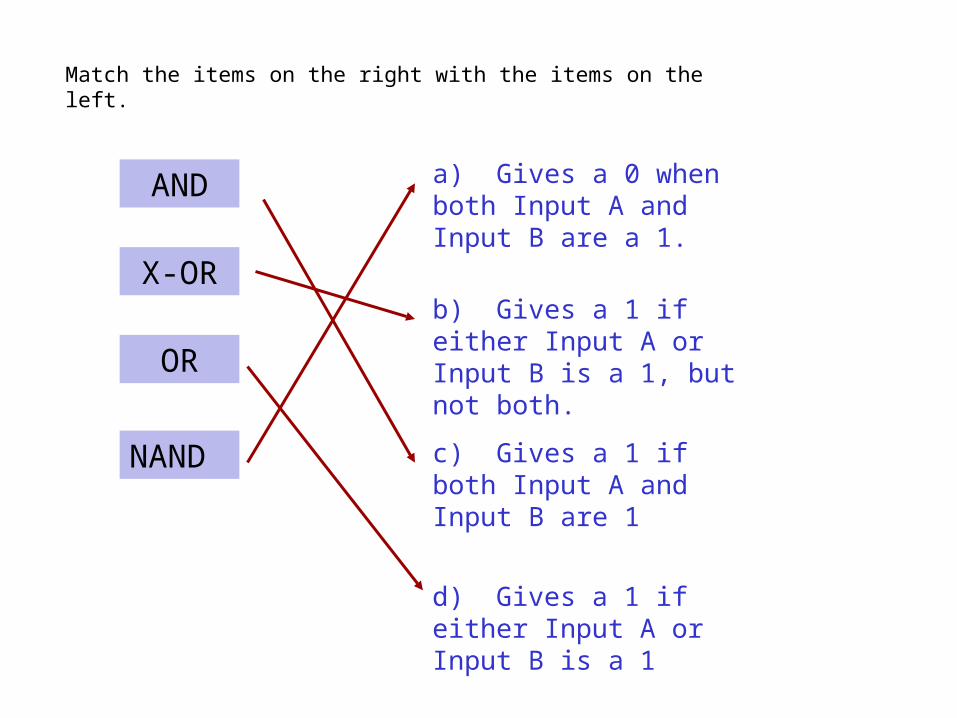
c) Gives a 1 if both Input A and Input B are 1
d) Gives a 1 if either Input A or Input B is a 1
b) Gives a 1 if either Input A or Input B is a 1, but not both.
a) Gives a 0 when both Input A and Input B are a 1.
OR
NAND
AND
X-OR
Match the items on the right with the items on the left.
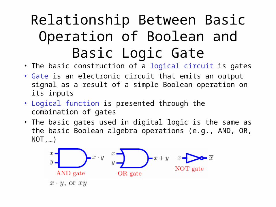
Relationship Between Basic Operation of Boolean and Basic Logic Gate
• The basic construction of a logical circuit is gates• Gate is an electronic circuit that emits an output signal
as a result of a simple Boolean operation on its inputs• Logical function is presented through the combination
of gates• The basic gates used in digital logic is the same as the
basic Boolean algebra operations (e.g., AND, OR, NOT,…)
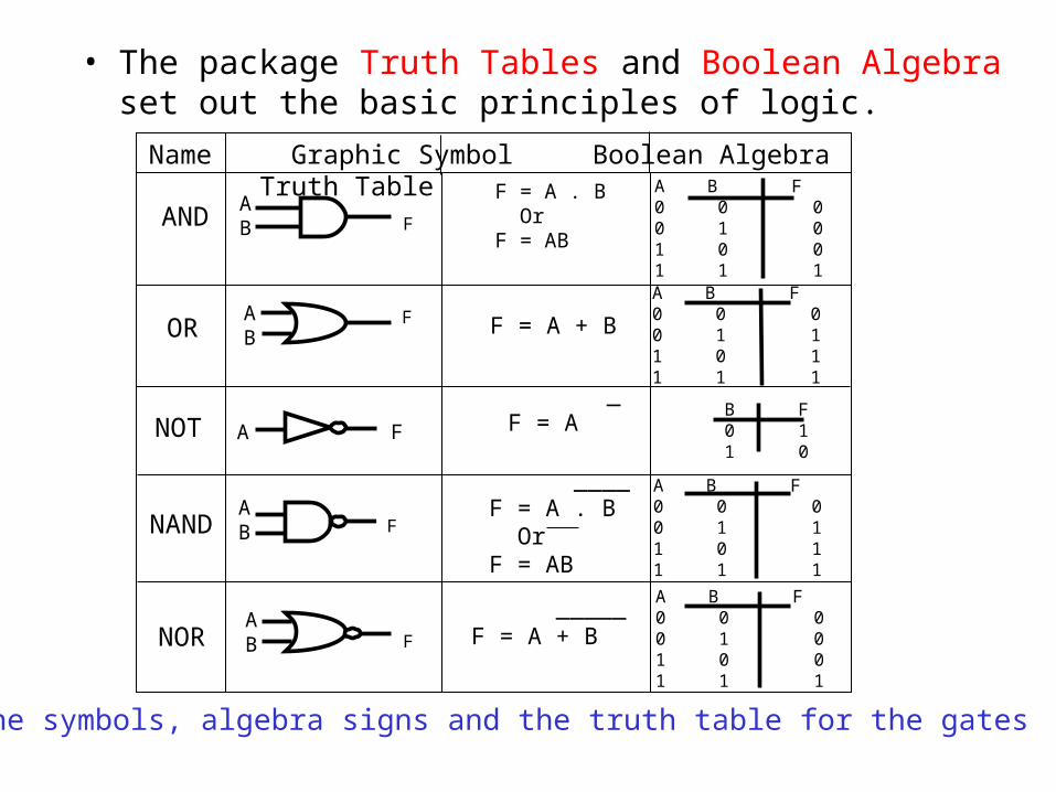
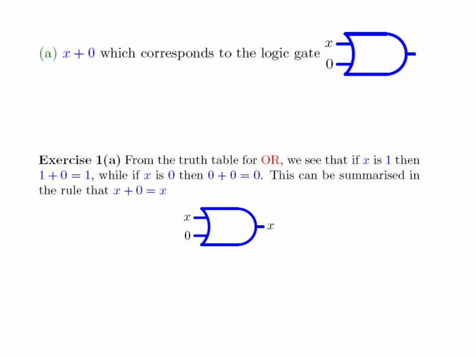
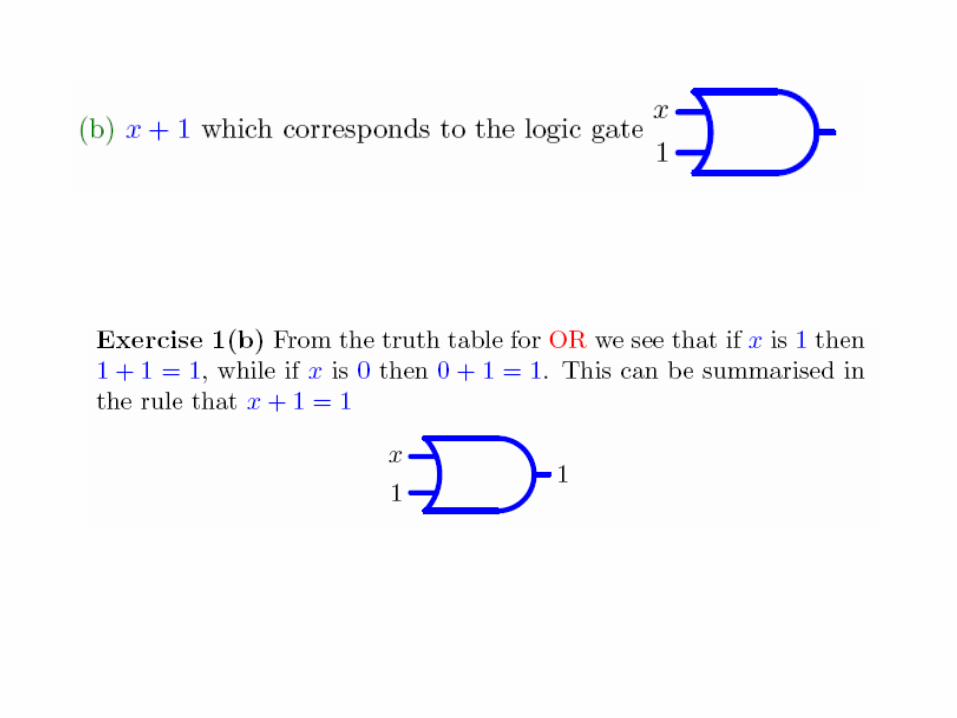
• The package Truth Tables and Boolean Algebra set out the basic principles of logic.
A B F0 0 00 1 01 0 01 1 1
A B F0 0 00 1 11 0 11 1 1
A B F0 0 00 1 11 0 11 1 1
A B F0 0 00 1 01 0 01 1 1
F
F
F
F
Name Graphic Symbol Boolean Algebra Truth Table
AB
AB
AB
AB
A F
AND
OR
NOT
NAND
NOR
F = A . B Or F = AB
F = A + B
_____ F = A + B
____ F = A . B Or F = AB
_ F = A
B F 0 1 1 0
the symbols, algebra signs and the truth table for the gates
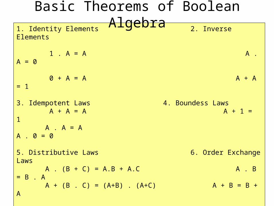
1. Identity Elements 2. Inverse Elements 1 . A = A A . A = 0 0 + A = A A + A = 1 3. Idempotent Laws 4. Boundess Laws A + A = A A + 1 = 1 A . A = A A . 0 = 0 5. Distributive Laws 6. Order Exchange Laws A . (B + C) = A.B + A.C A . B = B . A A + (B . C) = (A+B) . (A+C) A + B = B + A 7. Absorption Laws 8. Associative Laws A + (A . B) = A A + (B + C) = (A + B) + C A . (A + B) = A A . (B . C) = (A . B) . C 9. Elimination Laws 10. De Morgan Theorem A + (A . B) = A + B (A + B) = A . B A . (A + B) = A . B (A . B) = A + B
Basic Theorems of Boolean Algebra
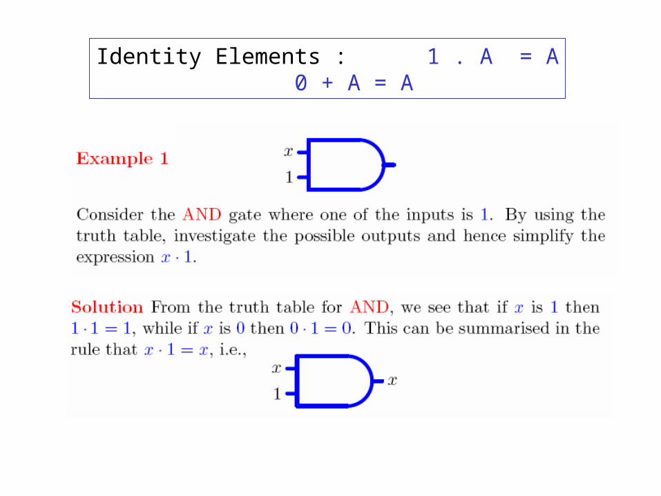
Identity Elements : 1 . A = A0 + A = A
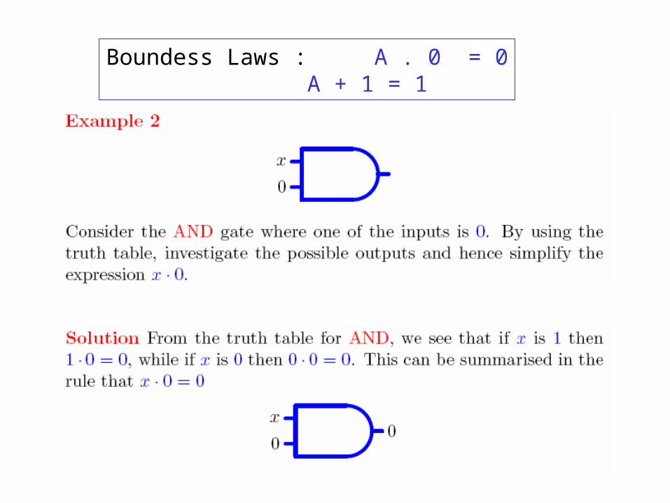
Boundess Laws : A . 0 = 0A + 1 = 1
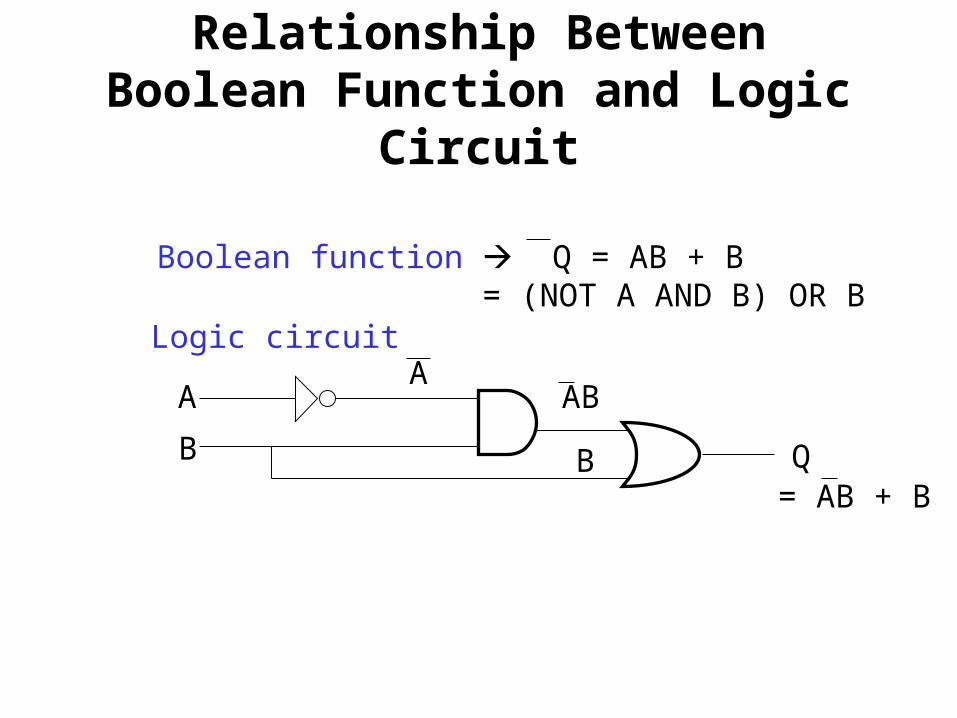
Relationship Between Boolean Function and Logic Circuit
A
B Q
Boolean function Q = AB + B = (NOT A AND B) OR B
Logic circuitA
AB
B= AB + B
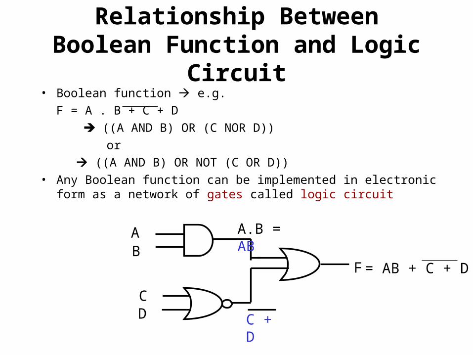
Relationship Between Boolean Function and Logic Circuit
• Boolean function e.g.
F = A . B + C + D
((A AND B) OR (C NOR D))
or
((A AND B) OR NOT (C OR D))
• Any Boolean function can be implemented in electronic form as a network of gates called logic circuit
AB
F
A.B = AB
CD C + D
= AB + C + D
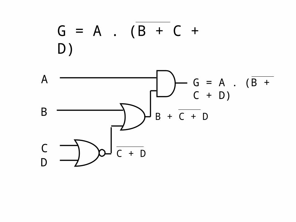
G = A . (B + C + D)
A
B
CD
G = A . (B + C + D)
C + D
B + C + D
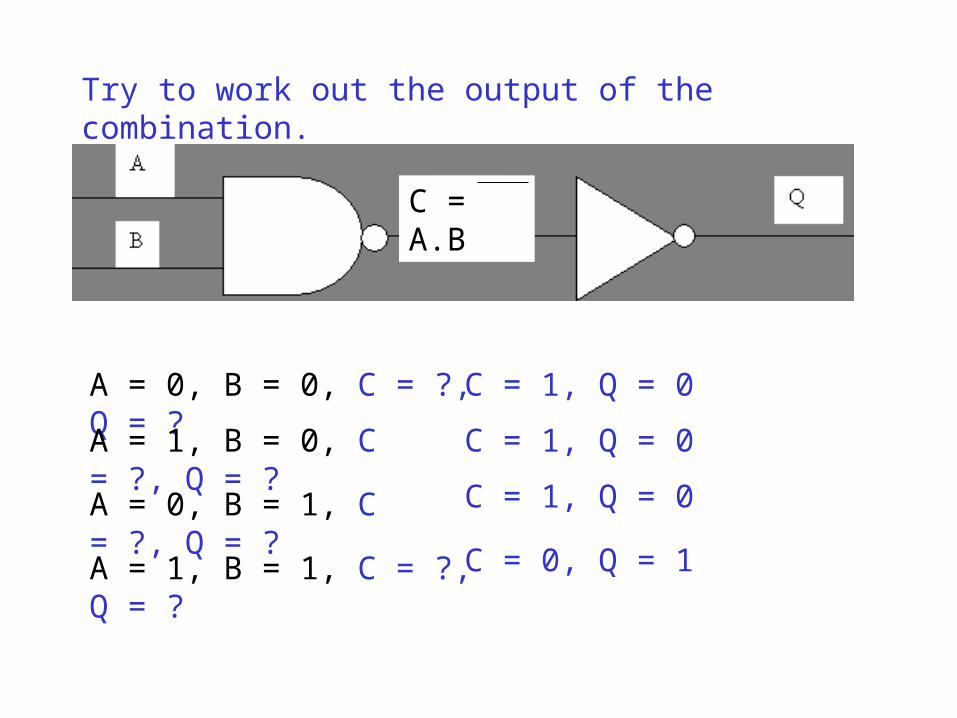
A = 0, B = 0, C = ?, Q = ?
A = 1, B = 0, C = ?, Q = ?
A = 0, B = 1, C = ?, Q = ?
A = 1, B = 1, C = ?, Q = ?
Try to work out the output of the combination.
C = A.B
C = 1, Q = 0
C = 1, Q = 0
C = 1, Q = 0
C = 0, Q = 1
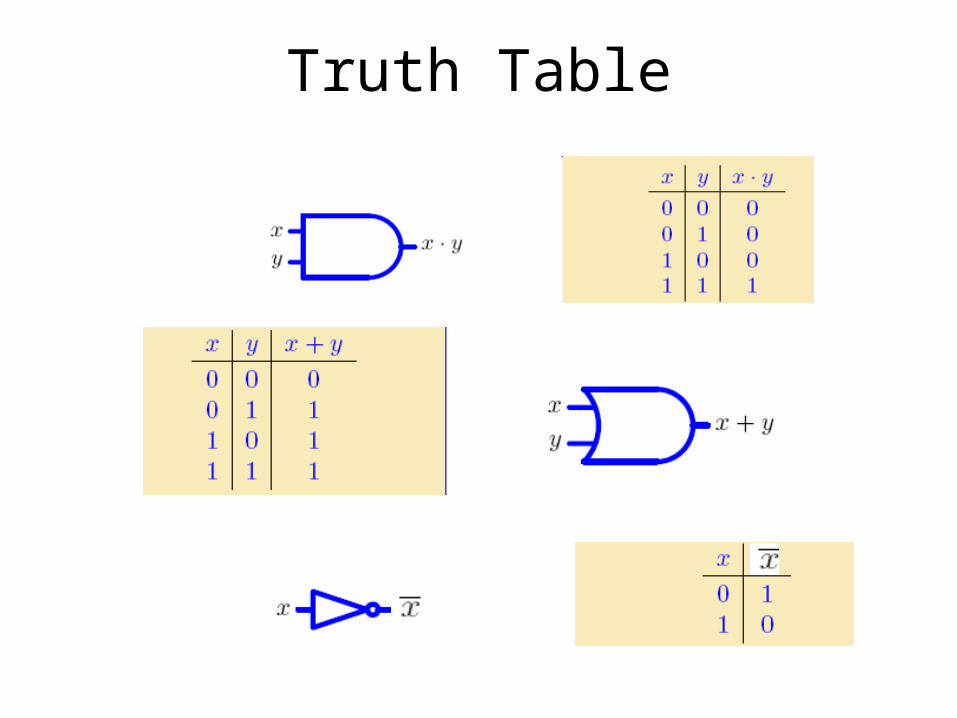
Truth Table
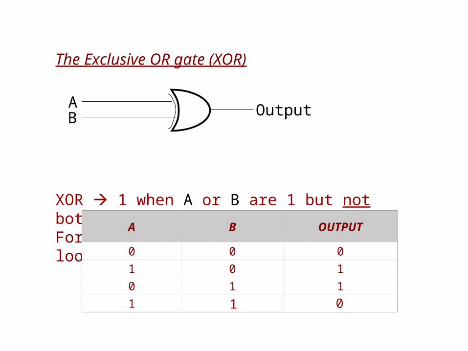
The Exclusive OR gate (XOR)
XOR 1 when A or B are 1 but not bothFor the XOR gate the truth table looks like this:
A B OUTPUT
0 0 0
1 0 1
0 1 1
1 1 0
AB Output
A
B
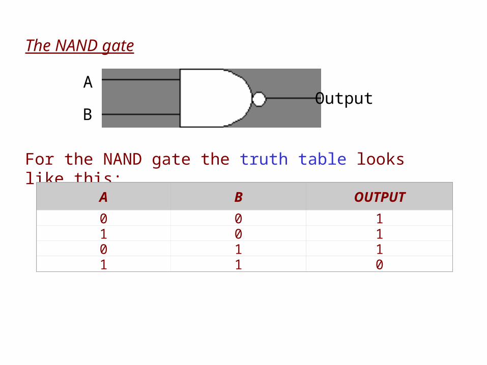
The NAND gate
For the NAND gate the truth table looks like this:
A B OUTPUT
0 0 11 0 10 1 11 1 0
Output
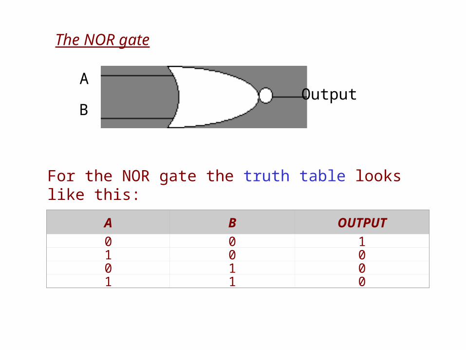
The NOR gate
A
BOutput
For the NOR gate the truth table looks like this:
A B OUTPUT0 0 11 0 00 1 01 1 0
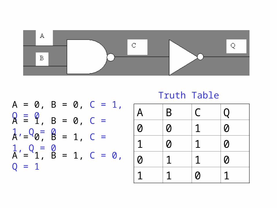
A B C Q
0 0 1 0
1 0 1 0
0 1 1 0
1 1 0 1
A = 0, B = 0, C = 1, Q = 0
A = 1, B = 0, C = 1, Q = 0
A = 0, B = 1, C = 1, Q = 0
A = 1, B = 1, C = 0, Q = 1
Truth Table
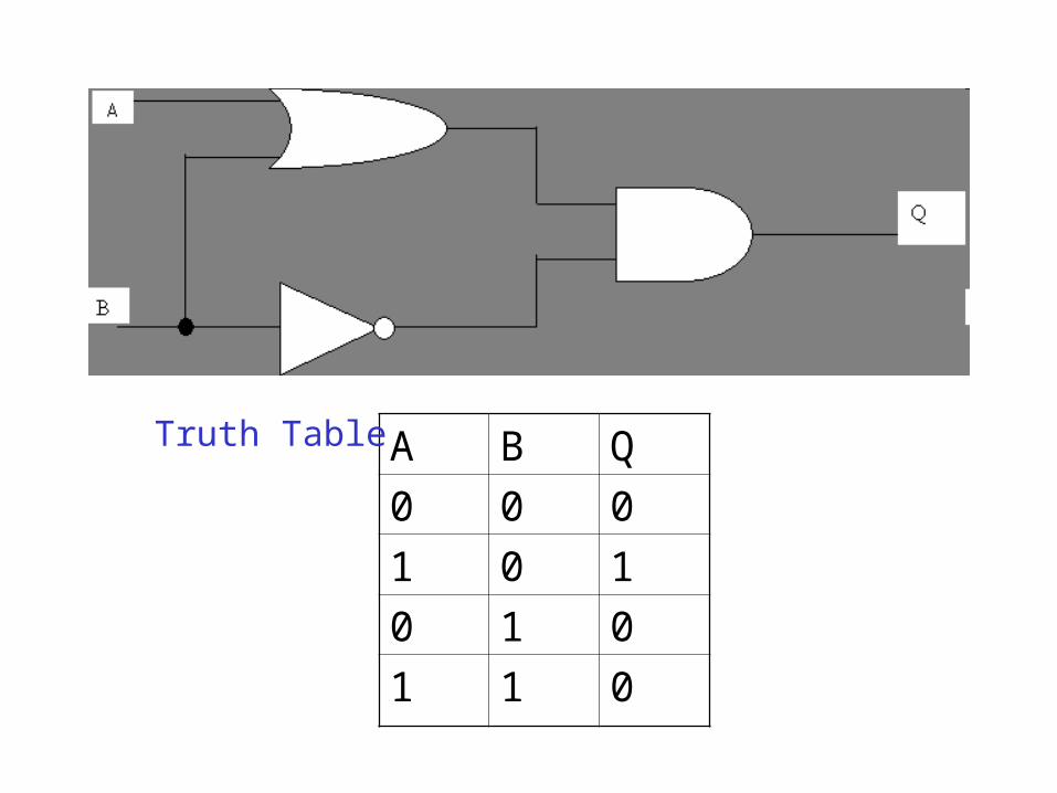
A B Q
0 0 0
1 0 1
0 1 0
1 1 0
Truth Table
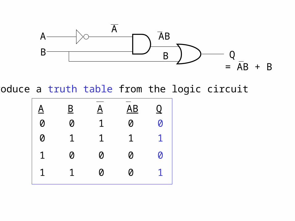
A
B Q
AAB
B= AB + B
Produce a truth table from the logic circuit
A B A AB Q
0 0 1 0 0
0 1 1 1 1
1 0 0 0 0
1 1 0 0 1
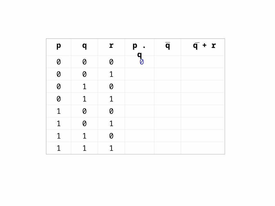
p q r p . qp . q qq q + rq + r
0 0 0 0
0 0 1
0 1 0
0 1 1
1 0 0
1 0 1
1 1 0
1 1 1
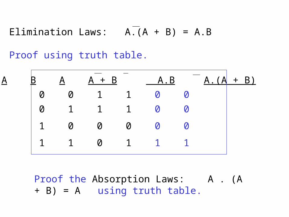
Elimination Laws: A.(A + B) = A.B
Proof using truth table.
A B A A + B A.B A.(A + B)
0 0 1 1 0 0
0 1 1 1 0 0
1 0 0 0 0 0
1 1 0 1 1 1
Proof the Absorption Laws: A . (A + B) = A using truth table.