Chapter 3. Adding Components with MML - Cisco€ Nortel Release Link Trunk (RLT) Support, page...
146
CHAPTER 1-1 Cisco PGW 2200 Softswitch Release 9.8 Provisioning Guide OL-18092-11 1 Adding Components with MML Revised: December 16, 2010, OL-18092-11 This chapter describes how to add components, describes how to verify the addition of the components, and gives tips that can help you solve problems. It includes the following sections: • How to Add Components, page 1-2 • Adding SS7 Signaling Route Components, page 1-3 • Adding SS7 Signaling Links, page 1-14 • Adding Media Gateway (MGW) Control Links, page 1-19 • Adding Trunks, Trunk Groups, and Routing, page 1-39 • Creating Profiles, page 1-58 • Provisioning Gateway Pools and Gateway Pool Profiles for H.248 Components, page 1-68 • Adding SIP Components, page 1-71 • Adding SIP-T and SIP-GTD Support, page 1-90 • Provisioning SIP-I, page 1-92 • Adding EISUP Links, page 1-94 • GTD NOA Override, page 1-96 • Configurable NOA Mapping, page 1-100 • Adding Location Labels for Call Limiting, page 1-103 • Adding Advice of Charge, page 1-113 • Adding Intelligent Network Application Part, page 1-115 • Adding Support for MGCP 1.0 and Additional MGCP Packages, page 1-116 • Adding Support of Partial CLI and CLI Code of Practice, page 1-117 • Scaling System Components, page 1-117 • Provisioning Examples, page 1-121 This chapter also provides basic provisioning procedures for the following features on the Cisco PGW 2200 Softswitch Release 9.8(1): • Display Name and Connected Number Interworking, page 1-124 • Domain Based Routing, page 1-125 • Enhanced Clear Channel Codec Support, page 1-125
Transcript of Chapter 3. Adding Components with MML - Cisco€ Nortel Release Link Trunk (RLT) Support, page...
Cisco PGOL-18092-11
C H A P T E R 1
Adding Components with MMLRevised: December 16, 2010, OL-18092-11
This chapter describes how to add components, describes how to verify the addition of the components, and gives tips that can help you solve problems. It includes the following sections:
• How to Add Components, page 1-2
• Adding SS7 Signaling Route Components, page 1-3
• Adding SS7 Signaling Links, page 1-14
• Adding Media Gateway (MGW) Control Links, page 1-19
• Adding Trunks, Trunk Groups, and Routing, page 1-39
• Creating Profiles, page 1-58
• Provisioning Gateway Pools and Gateway Pool Profiles for H.248 Components, page 1-68
• Adding SIP Components, page 1-71
• Adding SIP-T and SIP-GTD Support, page 1-90
• Provisioning SIP-I, page 1-92
• Adding EISUP Links, page 1-94
• GTD NOA Override, page 1-96
• Configurable NOA Mapping, page 1-100
• Adding Location Labels for Call Limiting, page 1-103
• Adding Advice of Charge, page 1-113
• Adding Intelligent Network Application Part, page 1-115
• Adding Support for MGCP 1.0 and Additional MGCP Packages, page 1-116
• Adding Support of Partial CLI and CLI Code of Practice, page 1-117
• Scaling System Components, page 1-117
• Provisioning Examples, page 1-121
This chapter also provides basic provisioning procedures for the following features on the Cisco PGW 2200 Softswitch Release 9.8(1):
• Display Name and Connected Number Interworking, page 1-124
• Domain Based Routing, page 1-125
• Enhanced Clear Channel Codec Support, page 1-125
1-1W 2200 Softswitch Release 9.8 Provisioning Guide

Chapter 1 Adding Components with MML How to Add Components
• Enhanced Generic Number Handling, page 1-126
• Enhanced Video Support, page 1-127
• Generic Call Tagging, page 1-129
• H.248 Protocol–Phase 2, page 1-129
• Inter-CUCM SIP Trunk Service Transparency for MWI, KPML, and COLP, page 1-131
• MLPP Support for ISUP and SIP Interworking and SIP to SIP Transparency, page 1-134
• Nortel Release Link Trunk (RLT) Support, page 1-135
• Secure Real-time Transport Protocol Support, page 1-137
• SIP Profile, page 1-137
• SIP-I Protocol, page 1-139
• Support of PAID Tel URI, page 1-140
• Support of SIP P-Headers for 3GPP, page 1-142
• TCP Transport for SIP, Phase II, page 1-144
How to Add ComponentsAdd the components in the following order:
1. Add external nodes for each device connected to the network.
2. Add point codes (OPC, DPC, and APC).
3. Add SS7 signaling service.
4. Add media gateway signaling service.
5. Add linksets.
6. Add C7 IP links (redundant).
7. Add links (IP or SIP).
8. Add SS7 routes.
9. Add SS7 subsystem.
10. Add trunks (x24 or x31).
Tip Use the planning worksheets in Appendix 1, “Planning Worksheets” to assemble the information you will need for provisioning.
To add a component, do the following:
Step 1 Start an MML session.
Step 2 Start a provisioning session as described in the “Starting a Provisioning Session” section on page 1-6.
The source configuration that you chose during startup determines the configuration to which you can add components.
Step 3 Enter the following command:
mml> prov-add:componentType:name="name",desc="description",paramName=value
1-2Cisco PGW 2200 Softswitch Release 9.8 Provisioning Guide
OL-18092-11
Chapter 1 Adding Components with MML Adding SS7 Signaling Route Components
Where:
• componentType is the type of component you want to create,
• description is the long name assigned that can be as many as 128 alphanumeric characters in length.
• name is the name you want to give to the component. The name can be as many as 20 characters long and can contain numbers, letters, and the dash (-) symbol.
• value is the parameter value of the component.
Note Fully define all components before you deploy a configuration.
Adding SS7 Signaling Route ComponentsTo provision routes between the Cisco PGW 2200 Softswitch and a destination device (for example, a switch), you must do the following:
1. Define the point codes (SS7 network addresses) of devices along the signaling route.
2. Define linksets.
3. Override linkset properties (if necessary).
4. Define C link as an SS7 subsystem for each pair of STPs.
5. Define an SS7 signaling service to support the signaling route.
6. Override the SS7 signaling service properties (if necessary).
7. Define the SS7 signaling route.
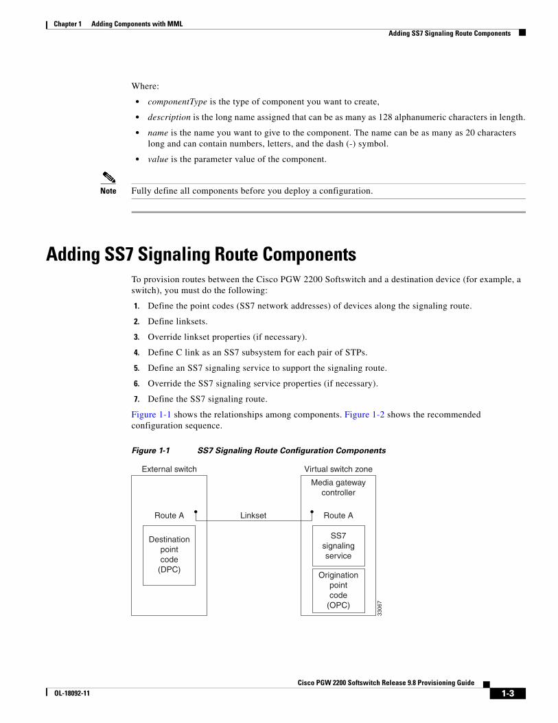
Figure 1-1 shows the relationships among components. Figure 1-2 shows the recommended configuration sequence.
Figure 1-1 SS7 Signaling Route Configuration Components
3306
7
Route A
Destinationpointcode
(DPC)
Route ALinkset
Media gatewaycontroller
Virtual switch zone
SS7signalingservice
External switch
Originationpointcode
(OPC)
1-3Cisco PGW 2200 Softswitch Release 9.8 Provisioning Guide
OL-18092-11

Chapter 1 Adding Components with MML Adding SS7 Signaling Route Components
Figure 1-2 SS7 Signaling Route Component Hierarchy
Your first task is to configure SS7 signaling routes that link the Cisco PGW 2200 Softswitch to the SS7 network nodes (signaling points). This process is described in the following sections:
• Adding Point Codes—OPC, DPC, and APC, page 1-4
• Adding a Linkset and Linkset Properties, page 1-9
• Adding SS7 Subsystems, page 1-10
• Adding an SS7 Route, page 1-12
• Adding an SS7 Signaling Service, page 1-13
Note When you provision routes, fully define all components (see Figure 1-2) before deploying a configuration.
Adding Point Codes—OPC, DPC, and APCA point code is an SS7 network address that identifies an SS7 network node, such as a switch, a service control points (SCP), a signal transfer point (STP), or a service switching point (SSP). To uniquely identify these network devices, you must assign a point code to each network device. You must get these point codes from your SS7 network administrator.
When configuring a Cisco PGW 2200 Softswitch, you must enter a point code and a point code type for each Cisco PGW 2200 Softswitch, along with the network address and the network indicator. The point code type is OPC and the point code address is a value in the form of x.x.x, such as 8.232.72.
Assemble the information you need to provision point codes by filling in the planning worksheets in Appendix 1, “Planning Worksheets” as follows:
• Table 1-2, Originating Point Code Configuration Parameters
• Table 1-3, Destination Point Code Configuration Parameters
• Table 1-4, Adjacent Point Code Configuration Parameters
Note ITU point codes are 14 bits long, and ANSI point codes are 24 bits long. The point code examples used in this document follow the ANSI SS7 (8bits.8bits.8bits) point code format. The Cisco PGW 2200 Softswitch can also support ITU point codes.
3306
8
OPCDPC
SS7signalingservice
SS7signalingserviceproperties
Linkset
Linksetproperties
SS7 route
1-4Cisco PGW 2200 Softswitch Release 9.8 Provisioning Guide
OL-18092-11

Chapter 1 Adding Components with MML Adding SS7 Signaling Route Components
Assign point codes as follows:
• Originating point codes (OPCs)—The point codes assigned to the Cisco PGW 2200 Softswitch. See the “Adding an Originating Point Code (OPC)” section on page 1-5.
• Adjacent point codes (APCs)—Point codes for an STP connected to the Cisco PGW 2200 Softswitch. See the “Adding an Adjacent Point Code (APC)” section on page 1-6.
• Destination point codes (DPCs)—Point codes assigned to each remote switch connected to the Cisco PGW 2200 Softswitch. See the “Adding a Destination Point Code (DPC)” section on page 1-6.
For additional technical information about adding point codes on the Cisco PGW 2200 Softswitch, see the “Understanding Point Code Addressing” section on page 1-6.
Adding an Originating Point Code (OPC)
This section explains how to add OPCs.
Depending on your system configuration, you may have to assign more than one OPC to a single Cisco PGW 2200 Softswitch. When adding multiple OPCs, keep the following information in mind:
• ITU point codes contain 14 bits and ANSI point codes contain 24 bits.
Note Use care when provisioning point codes because they are not checked in the provisioning session.
• A maximum of 6 true OPCs can be supported per Cisco PGW 2200 Softswitch.
• For each true OPC, there can be a maximum of 8 capability OPCs.
• For each OPC added, you must specify a different local port number for each C7 IP link on the same interface.
• For each OPC added, you must create a duplicate DPC with a different name but with the same point code.
• Enter the OPC before creating the C7 IP link.
• When specifying a local port number, it must be greater than 1024 (for example, 7000).
• Each OPC requires its own linkset (a linkset cannot be shared by 2 OPCs).
• A maximum of 2 Session Manager sessions (1 active and 1 standby) can be supported per Cisco PGW 2200 Softswitch (1 session per link).
• A maximum of 192 links can be supported per Cisco PGW 2200 Softswitch.
• A maximum of 16 linksets can be included per Control Channel.
• A maximum of 4096 DS0s (CICs) can be supported per OPC-DPC pair for ITU or a maximum of 16, 384 DS0s (CICs) for ANSI.
To add a point code to the Cisco PGW 2200 Softswitch configuration, use the PROV-ADD command as follows:
Step 1 Use the following MML command to add the component and required parameters.
mml> prov-add:opc:name="opc1",desc="OPC1",netaddr="1.2.1",netind=2,type="trueopc"
Step 2 Use the following MML command to add the component and required parameters.
1-5Cisco PGW 2200 Softswitch Release 9.8 Provisioning Guide
OL-18092-11
Chapter 1 Adding Components with MML Adding SS7 Signaling Route Components
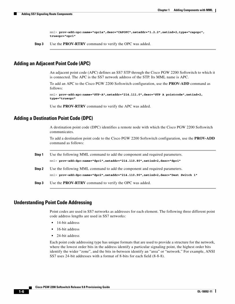
mml> prov-add:opc:name="opc1a",desc="CAPOPC",netaddr="1.2.2",netind=2,type="capopc",trueopc="opc1"
Step 3 Use the PROV-RTRV command to verify the OPC was added.
Adding an Adjacent Point Code (APC)
An adjacent point code (APC) defines an SS7 STP through the Cisco PGW 2200 Softswitch to which it is connected. The APC is the SS7 network address of the STP. Its MML name is APC.
To add an APC to the Cisco PGW 2200 Softswitch configuration, use the PROV-ADD command as follows:
mml> prov-add:apc:name="STP-A",netaddr="214.111.0",desc="STP A pointcode",netind=2,type="trueopc"
Use the PROV-RTRV command to verify the APC was added.
Adding a Destination Point Code (DPC)
A destination point code (DPC) identifies a remote node with which the Cisco PGW 2200 Softswitch communicates.
To add a destination point code to the Cisco PGW 2200 Softswitch configuration, use the PROV-ADD command as follows:
Step 1 Use the following MML command to add the component and required parameters.
mml> prov-add:dpc:name="dpc1",netaddr="214.110.80",netind=2,desc="dpc1"
Step 2 Use the following MML command to add the component and required parameters.
mml> prov-add:dpc:name="dpc2",netaddr="214.110.90",netind=2,desc="Dest Switch 1"
Step 3 Use the PROV-RTRV command to verify the OPC was added.
Understanding Point Code Addressing
Point codes are used in SS7 networks as addresses for each element. The following three different point code address lengths are used in SS7 networks:
• 14-bit address
• 16-bit address
• 24-bit address
Each point code addressing type has unique formats that are used to provide a structure for the network, where the lowest order bits in the address identify a particular signaling point, the highest order bits identify the wider “zone”, and the bits in-between identify an “area” or “network.” For example, ANSI SS7 uses 24-bit addresses with a format of 8-bits for each field (8-8-8).
1-6Cisco PGW 2200 Softswitch Release 9.8 Provisioning Guide
OL-18092-11

Chapter 1 Adding Components with MML Adding SS7 Signaling Route Components
Note An exception to this is found in Japanese ISUP, in which the order is reversed (that is, the lowest order bits identify the wider “zone” and the highest order bits identify a particular signaling point).
Note Another exception is found in some National ITU SS7 variants, where there may be more or less than three fields used in the point code format. However, the ordering concept for the bits (bits in lower order fields are lower in the network hierarchy) still applies.
You can find more information about point code addressing and how it is handled in the Cisco PGW 2200 Softswitch software in the following sections:
• 14-Bit Address (ITU), page 1-7
• 16-Bit Address (Japan), page 1-8
• 24-Bit Address (ANSI and China), page 1-9
• Cisco PGW 2200 Softswitch Point Code Storage, page 1-9
14-Bit Address (ITU)
The 14-bit address is used to identify point codes in countries that conform to the ITU SS7 recommendations. In ITU SS7 networks, there are two types of point code: International and National. International point codes always conform to the format (3-bits/8-bits/3-bits or 3-8-3) defined in ITU Recommendation Q.704, which is illustrated in Figure 1-3. There are many formats used to define National point codes. For example, the Singapore National point code format is 6-4-4. The formats for National point codes are defined in each ITU SS7 National variant recommendation.
Figure 1-3 14-bit Address Point Code Format - International Point Code
The decimal value of the maximum point code for an International 14-bit address is 7.255.7. The decimal value of the maximum point code for a National 14-bit address varies. For a Singapore National point code maximum value would be 63.15.15.
Note When you provision an ITU point code on the Cisco PGW 2200 Softswitch, you must use the International point code format. If the point code provided to you is in a National point code format, convert the point code into International format using the procedure in “Converting National Point Codes To International Point Code Values” section on page 1-7.
Converting National Point Codes To International Point Code Values
The key to converting ITU National point codes to ITU International point code values is knowing the format of the National point codes, which can be found in the National SS7 variant recommendations.
To convert an ITU National point code to an International point code value, perform the following steps:
13 12 11 10 9 8 7 6 5 4 3 2 1 0
Zone identification3 bits
Area/network identification8 bits
Signaling point identification3 bits
1-7Cisco PGW 2200 Softswitch Release 9.8 Provisioning Guide
OL-18092-11

Chapter 1 Adding Components with MML Adding SS7 Signaling Route Components
Step 1 Convert the decimal value of the National point code into binary, using the associated point code format as a reference.
Note If you do not know the format for a National point code, you must consult the recommendations for that National SS7 variant.
For example, if you wanted to convert a Singapore National point code of 54-3-3 to its binary value, you would apply the Singapore National point code format, which is 6-4-4. This would result in a binary value of 110110.0011.0011 or 11011000110011, with the National point code format removed.
Step 2 Apply the International point code format to the binary number, and convert back to decimal.
Staying with the preceding example, you would apply the International point code format, which is 3-8-3, to the binary value 11011000110011, or 110.11000110.011. This would result in a decimal value of 6.198.3.
16-Bit Address (Japan)
A 16-bit address is used to identify point codes in Japan. There are two standards agencies in Japan, the Telecommunications Technology Committee (TTC) and Nippon Telephone and Telegraph (NTT). The 16-bit address point code format is defined in the JT-Q704 and NTT-Q704-b recommendations. These documents divide the point code into three fields (7-4-5), as seen in Figure 1-4.
Figure 1-4 16-bit Address Point Code Format
The TTC recommendation (JT-Q704) uses the same terminology to describe the sub-fields as the ITU Recommendation Q.704. The NTT recommendation (NTT-Q704-b) uses unique terms for these sub-fields. The NTT names for these sub-fields appear in Figure 1-4 in parenthesis.
Note Point codes in the Cisco PGW 2200 Softswitch software are all provisioned in the zone.area/network.signaling point format. When you provision a point code for Japanese ISUP on the Cisco PGW 2200 Softswitch, the order of the fields must be reversed to match that format. For example, if you want to connect to a destination that uses Japanese ISUP with a point code of 78.9.20, you would provision a DPC on the Cisco PGW 2200 Softswitch with a point code of 20.9.78. The Cisco PGW 2200 Softswitch transmits the DPC address in the correct order (78.9.20).
The decimal value of the maximum point code for a 16-bit address is 127.15.31. The maximum point code value that you can provision on the Cisco PGW 2200 Softswitch is 31.15.127 because Japanese point code values must be reversed when provisioned on the Cisco PGW 2200 Softswitch.
15 14 13 12 11 10 9 8 7 6 5 4 3 2 1 0
Signaling point identification(Unit Number)7 bits
Area/network identification (Sub Number Area)4 bits
Zone identification(Main Number Area)5 bits
1-8Cisco PGW 2200 Softswitch Release 9.8 Provisioning Guide
OL-18092-11

Chapter 1 Adding Components with MML Adding SS7 Signaling Route Components
24-Bit Address (ANSI and China)
The 24-bit address is used to identify point codes in China and countries that conform to the ANSI SS7 recommendations. The 24-bit address is divided into three 8-bit fields (8-8-8), as defined in the Chinese GF001-9001 and ANSI T1.111.4 recommendations, which can be seen in Figure 1-5.
The Chinese GF001-9001 recommendation uses the same terminology to describe the sub-fields as the ITU Recommendation Q.704. The ANSI T1.111.4 recommendation (uses unique terms for these sub-fields. The ANSI names for these sub-fields appear in Figure 1-5 in parenthesis.
The decimal value of the maximum point code for a 24-bit address is 255.255.255.
Cisco PGW 2200 Softswitch Point Code Storage
The Cisco PGW 2200 Softswitch uses a 32-bit field to store point code addresses. When you provision a point code on the Cisco PGW 2200 Softswitch, the format used depends upon the associated protocol. The Cisco PGW 2200 Softswitch software pads the unused bits in the field with zeros when the point code is saved.
For example, if you provisioned a DPC of 6.198.3 for an ITU SS7 network, it would have a binary equivalent of 110.11000110.011, and would be stored in the Cisco PGW 2200 Softswitch as 00000000000000000011011000110011.
Adding a Linkset and Linkset PropertiesThis section explains how to add a linkset and linkset properties.
Assemble the information you need to provision linksets and linkset properties by filling in the planning worksheet, Table 1-6, Linkset Configuration Parameters.
Linkset
After you determine the point codes for your network devices, you must define the linksets that connect each Cisco PGW 2200 Softswitch node directly to a remote switch or indirectly to the remote switch through an STP. A linkset is the group of all communication links connecting an Cisco PGW 2200 Softswitch node to a specific SSP or STP. When two STPs are defined as mates within the Cisco PGW 2200 Softswitch software, the Cisco PGW 2200 Softswitch can use either linkset to connect to the SS7 signaling network.
A linkset can contain from 1 to 16 links.
For information on linkset properties, see MML Command Reference.
To add a linkset to the Cisco PGW 2200 Softswitch configuration, use the PROV-ADD command as follows:
Figure 1-5 24-bit Address Point Code Format
23 22 21 20 19 18 17 16 15 14 13 12 11 10 9 8 7 6 5 4 3 2 1 0
Zone identification(Network Octet)8 bits
Area/Network identification (Cluster Octet)8 bits
Signaling Point identification (Member Octet)8 bits
1-9Cisco PGW 2200 Softswitch Release 9.8 Provisioning Guide
OL-18092-11

Chapter 1 Adding Components with MML Adding SS7 Signaling Route Components
Step 1 Use the following MML command to add the component and required parameters.
mml> prov-add:lnkset:name="linkset1",desc="linkset 1 to STP-A",apc="STP-A",type="IP", proto="SS7-ANSI"
Step 2 Use the following MML command to add the component and required parameters.
mml> prov-add:lnkset:name="linkset2",desc="linkset 2 to STP-B",apc="STP-B",type="IP", proto="SS7-ANSI"
Step 3 Use the PROV-RTRV command to verify the linkset was added.
Note When configuring linksets for STP connections, you usually configure two linksets for each pair of STPs.
Tip Setting up linksets is a two-step process that consists of first adding the linkset and then adding links to the linkset.
Linkset Property
Linksets have a number of properties that you can use to tune linkset communications. You can change one or more linkset properties in a single command.
For information on linkset properties, see MML Command Reference.
To add a linkset property, use the PROV-ADD command as follows:
mml> prov-add:lnksetprop:name="SS7-ANSI",layerRetries="6",layerTimer="6", sendAfterRestart="6", slsTimer="6",sstTimer="302",dialogRange="2",standard="ITU90"
Adding SS7 SubsystemsThis section explains how to add SS7 subsystems. You can define SS7 subsystems to add
• Mated STPs, page 1-10
• Local number portability (LNP) Services, page 1-11
• Advanced Intelligent Network (AIN) Services, page 1-12
Assemble the information you need to provision SS7 subsystems by filling in the planning worksheet, Table 1-12, SS7 Subsystem Worksheet Example.
Mated STPs
An SS7 subsystem allows the Cisco PGW 2200 Softswitch to route traffic over the C-links between mated STPs to increase network reliability. When two STPs are defined as mates within the Cisco PGW 2200 Softswitch software, the software can use either STP for communications with an external switch.
You must define one SS7 subsystem for each STP to which the Cisco PGW 2200 Softswitch connects.
For information on SS7 subsystem properties, see MML Command Reference.
1-10Cisco PGW 2200 Softswitch Release 9.8 Provisioning Guide
OL-18092-11

Chapter 1 Adding Components with MML Adding SS7 Signaling Route Components
To add an SS7 subsystem for mated STPs to the Cisco PGW 2200 Softswitch, use the PROV-ADD command as follows:
Step 1 Use the following MML command to add the component and required parameters:
mml> prov-add:ss7subsys:name="mate1",svc="STPA",matedapc="STPB",proto="SS7-ANSI",pri=1,desc="mate STPA to STPB"
Step 2 Use the following MML command to add the component and required parameters:
mml> prov-add:ss7subsys:name="mate2",svc="STPB",matedapc="STPA",proto="SS7-ANSI",pri=2,desc="mate STPB to STPA"
Note You must define one SS7 subsystem for each STP to which the Cisco PGW 2200 Softswitch connects.
Step 3 Use the PROV-RTRV command to verify the SS7 subsystem was added.
The following MML commands provide an example of other components to add when adding a mated STP:
mml> prov-add:APC:NAME="STPA-5-83-230",DESC="STPA LA 5-83-230",NETADDR="5.83.230",NETIND=2 mml> prov-add:APC:NAME="STPB-5-83-231",DESC="STPB LA 5-83-231",NETADDR="5.83.231",NETIND=2 mml> prov-add:LNKSET:NAME="ls1",DESC="Linkset from STPA to pgw2200",APC="STPA-5-83-230",PROTO="SS7-ANSI",TYPE="IP" mml> prov-add:LNKSET:NAME="ls2",DESC="Linkset from STPB to pgw2200",APC="STPB-5-83-231",PROTO="SS7-ANSI",TYPE="IP"
mml> prov-add:SS7ROUTE:NAME="ss7rte1-la",DESC="SS7 route set on ls1 to LA switch",OPC="opc-itxc-la",DPC="dpc-la",LNKSET="ls1",PRI=1 mml> prov-add:SS7ROUTE:NAME="ss7rte2-la",DESC="SS7 route set on ls2 to LA switch",OPC="opc-itxc-la",DPC="dpc-la",LNKSET="ls2",PRI=1
mml> prov-add:SS7ROUTE:NAME="route-STPA",DESC="route to STPA",OPC="opc-itxc-la",DPC="stpA-5-83-231",LNKSET="ls1",PRI=1 mml> prov-add:SS7ROUTE:NAME="route-stpB",DESC="route to STPB",OPC="opc-itxc-la",DPC="STPB-5-83-230",LNKSET="ls2",PRI=1
Tip Protocol families must be the same for mated subsystems. If one pair of STPs handles both ITU and ANSI variants, you must configure two pairs of STPs, one for ITU and the other for ANSI.
Local number portability (LNP) Services
The SS7 subsystem provides local number portability (LNP) support through an SCP. Because the SS7 subsystem is an instance of an application, you need to configure a subsystem for each application type of service (for example, LNP).
To add an SS7 subsystem for LNP services to the Cisco PGW 2200 Softswitch, use the PROV-ADD command as follows:
Step 1 Use the following MML command to add the component and required parameters:
1-11Cisco PGW 2200 Softswitch Release 9.8 Provisioning Guide
OL-18092-11

Chapter 1 Adding Components with MML Adding SS7 Signaling Route Components
mml> prov-add:ss7subsys:name="LNP-1",svc="stpa",transproto="SCCP",proto="SS7-ANSI",pri=1,ssn=231,desc="LNP231 for STP A"
Step 2 Use the PROV-RTRV command to verify the subsystem number was added.
Advanced Intelligent Network (AIN) Services
The SS7 subsystem is also used to connect an STP to an SCP database for advanced intelligent network (AIN) queries. In this case, there is no mated STP parameter, matedapc, in the provisioning command.
You can use the SS7 subsystem to define an SCP using TCAP. For TCAP applications, TRANSPROTO is set to TCPIP and the subsystem number is set to a value greater than 0 to support AIN. You also must set STPSCPIND to route to the appropriate SCP.
For information on SS7 subsystem parameters, including STPSCPIND, see MML Command Reference.
To add an SS7 subsystem for AIN services to the Cisco PGW 2200 Softswitch, use the PROV-ADD command as follows:
Step 1 Use the following MML command to add the component and required parameters:
mml> prov-add:ss7subsys:name="AIN-1",svc="stpb",transproto="SCCP",proto="SS7-ANSI",pri=1,ssn=241,desc="AIN8xx for STP B"
Step 2 Use the PROV-RTRV command to verify the subsystem number was added.
Adding an SS7 RouteAn SS7 route is a path from the Cisco PGW 2200 Softswitch to another Cisco PGW 2200 Softswitch or SSP switch. Its MML name is SS7ROUTE.
SS7 routes are defined by the point codes along the path and the linksets that lead from the Cisco PGW 2200 Softswitch node through the STPs to each DPC.
Assemble the information you need to provision SS7 routes by filling in the planning worksheet, Table 1-9, SS7 Route Worksheet Example.
For information on SS7 route parameters, see MML Command Reference.
Note It is a good practice to define two routes to each remote switch. Each route should pass through a different STP in a mated pair. The linkset parameter, LNKSET, defines which STP a route will follow.
To add an SS7 route to the Cisco PGW 2200 Softswitch configuration, use the PROV-ADD command as follows:
Step 1 Use the following MML command to add the component and required parameters:
mml> prov-add:ss7route:name="rte1DPC1",opc="OPC",dpc="DestSW1PC",lnkset="linkset1", pri=1,desc="route 1 to DestSW1 thru STP-A"
Step 2 Use the following MML command to add the component and required parameters:
1-12Cisco PGW 2200 Softswitch Release 9.8 Provisioning Guide
OL-18092-11

Chapter 1 Adding Components with MML Adding SS7 Signaling Route Components
mml> prov-add:ss7route:name="rte2DPC1",opc="OPC",dpc="DestSW1PC",lnkset="linkset2", pri=1,desc="route 2 to DestSW1 thru STP-B"
Step 3 Use the PROV-RTRV command to verify the SS7 route was added.
Tip You must create a route for each DPC-OPC combination.You must create a route for each linkset.
Adding an SS7 Signaling ServiceAn SS7 signaling service specifies the protocol variant and the path that the Cisco PGW 2200 Softswitch uses to communicate with a remote switch (SSP) sending bearer traffic to the media gateways. You must define a separate service for each remote switch. Its MML name is SS7PATH.
Assemble the information you need to provision an SS7 signaling service by filling in the following planning worksheet:
• Table 1-16, SS7 Signaling Service Configuration Parameters.
• Table 1-17, SS7 Signaling Service Worksheet Example
For information on signaling service parameters, see MML Command Reference.
To add an SS7 signaling service to the Cisco PGW 2200 Softswitch configuration, use the PROV-ADD command as follows:
mml> prov-add:ss7path:name="ss7svc1",mdo="ANSISS7_STANDARD",dpc="dpc1",opc="opc1",desc="SS7 svc to dpc1"
Use the PROV-RTRV command to verify that the SS7 signaling service was added.
Tip Do not change the default values for CUSTGRPID and CUSTGRTBL. They are used for DPNSS feature transparency.
CUSTGRPID also associates variants and dial plans. Use the PROV-RTRV:VARIANTS command to see valid variants.
Changing SS7 Signaling Service PropertiesSS7 signaling service properties serve as additional configuration parameters that you can use to tune signaling service communications.
For properties and their associate components, see Chapter 6, “Properties” of MML Command Reference.
To change properties of an SS7 signaling service on the Cisco PGW 2200 Softswitch, use the PROV-ADD command as follows:
mml> PROV-ADD:SIGSVCPROP:NAME="ss7svc1",GNINCLUDE=1"
Note You do not need to configure all of the parameters to create an SS7 signaling service.
1-13Cisco PGW 2200 Softswitch Release 9.8 Provisioning Guide
OL-18092-11

Chapter 1 Adding Components with MML Adding SS7 Signaling Links
Adding SS7 Signaling LinksCisco PGW 2200 Softswitch supports two types of communication links to the signaling points (SPs), like STPs and SSPs:
• Cisco ITP-L links—ITP-L links use the Cisco ITP-L to offload MTP 1 and MTP 2 processing.
• ITP links—The Cisco PGW 2200 Softswitch performs all signal processing including MTP 1 and MTP 2 processing.
Signaling links are responsible for carrying traffic; while linksets define which SP a given route uses, links carry the communication traffic.
The following sections describe how to set up SS7 signaling links:
• Adding Signaling Links Through Cisco ITP-Ls, page 1-14
• Adding Signaling Links Through IP Transfer Points (ITPs), page 1-17
Assemble the information you need to provision a Cisco ITP-L linkset by filling in the planning worksheet, Table 1-18, Cisco ITP-L Linkset Worksheet Example.
Note It is best to plan SS7 routes before you configure links, because you define APCs and linksets when defining routes, and you must plan and configure these components before you can configure links. For more information about SS7 signaling routes, see the “Adding an SS7 Route” section on page 1-12.
Adding Signaling Links Through Cisco ITP-LsAfter configuring the SS7 signaling routes, you need to configure the C7 IP signaling link component. It identifies a link between a Cisco ITP-L, and the SS7 network (SSP or STP).
Cisco AS5350, AS5400, or AS5400 HPX can serve as an integrated Signaling Link Terminal (iSLT). The procedure for adding signaling links through iSLTs are the same as that for Cisco ITP-Ls.
Within the Cisco PGW 2200 Softswitch node, the ends of each link are identified as follows:
• At the Cisco PGW 2200 Softswitch end of each link, the link is associated with an Ethernet interface, an IP address, and a User Data Protocol (UDP) port.
• At the Cisco ITP-L end of each link, the link is identified with an IP address and a UDP port.
Its MML name is C7IPLNK. For information on C7 IP link parameters, see MML Command Reference.
Tip For SS7 provisioning, keep the following points in mind.A maximum of six OPCs that can be supported.Enter routing information for the OPC before creating the C7 IP link.For each OPC added, you must specify a different local port for each C7 IP link.Provision a maximum of 32 links per local port number. Specify another port number for each additional group of 32 links.Use the same port number for links in the same linkset.
Tip When expanding a network past 32 links, spreading the links evenly across the ports is recommended to prevent service interruption.
1-14Cisco PGW 2200 Softswitch Release 9.8 Provisioning Guide
OL-18092-11

Chapter 1 Adding Components with MML Adding SS7 Signaling Links
Tip Use this component only when the Cisco PGW 2200 Softswitch uses Cisco ITP-Ls to communicate SS7 messages over IP.
Assemble the information you need to provision C7 IP links by filling in the planning worksheet, Table 1-7, C7 IP Link Configuration Parameters.
You can add signaling links through Cisco ITP-Ls to the Cisco PGW 2200 Softswitch by:
• Adding a Cisco ITP-L External Node, page 1-15
• Adding a Session Set, page 1-15
• Adding C7 IP Links, page 1-16
Adding a Cisco ITP-L External Node
To add an Cisco ITP-L external node on the Cisco PGW 2200 Softswitch, use the PROV-ADD command as follows:
mml> prov-add:extnode:name="itpl1",desc="ITP-L 1",type="SLT"
Use the PROV-RTRV command to verify the session set was added.
Adding a Session Set
The session set component is used for ISDN and SS7 backhaul over Reliable UDP (RUDP) links. A session set is a pair of backhaul IP links that the Cisco PGW 2200 Softswitch uses to communicate with external nodes that support IPFAS. You must identify each link in the session set by specifying a port, an IP address, and a peer address for the Cisco PGW 2200 Softswitch end of the link.
You must specify one or two (if the IPADDR2 and PEERADDR2 parameters are specified) backhaul IP links.
A sessionset represents a pair of backhaul IP links used on the Cisco PGW 2200 Softswitch. These links are used to communicate with external nodes that support IPFAS or BSMV0.
Keep the following rules in mind when provisioning a session set:
• The PEERPORT and PEERADDRESS must be unique for each backhaul IP link created.
• IPADDR1 and IPADDR2 must be different. PEERADDR1 and PEERADDR2 must be different, except when the EXTNODE is a VISM (MGX8850).
• A maximum of 50 IPFAS session sets are supported per port.
• The following attributes cannot be modified:
– NAME
– EXTNODE
– TYPE
• The ISDNSIGTYPE of the EXTNODE must be N/A.
• The session set TYPE must be BSMV0 for C7 session sets.
• The session set TYPE must be IPFAS for IPFAS session sets.
• IP addresses cannot be split across session sets. For example if SET 1 has IP_Addr1 and IP_Addr2, then SET 2 cannot have IP_Addr1 and IP_Addr3.
1-15Cisco PGW 2200 Softswitch Release 9.8 Provisioning Guide
OL-18092-11
Chapter 1 Adding Components with MML Adding SS7 Signaling Links
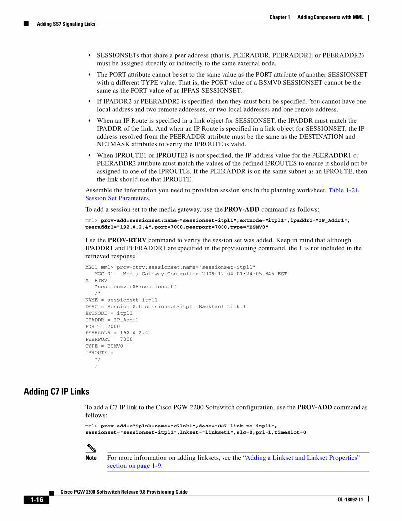
• SESSIONSETs that share a peer address (that is, PEERADDR, PEERADDR1, or PEERADDR2) must be assigned directly or indirectly to the same external node.
• The PORT attribute cannot be set to the same value as the PORT attribute of another SESSIONSET with a different TYPE value. That is, the PORT value of a BSMV0 SESSIONSET cannot be the same as the PORT value of an IPFAS SESSIONSET.
• If IPADDR2 or PEERADDR2 is specified, then they must both be specified. You cannot have one local address and two remote addresses, or two local addresses and one remote address.
• When an IP Route is specified in a link object for SESSIONSET, the IPADDR must match the IPADDR of the link. And when an IP Route is specified in a link object for SESSIONSET, the IP address resolved from the PEERADDR attribute must be the same as the DESTINATION and NETMASK attributes to verify the IPROUTE is valid.
• When IPROUTE1 or IPROUTE2 is not specified, the IP address value for the PEERADDR1 or PEERADDR2 attribute must match the values of the defined IPROUTES to ensure it should not be assigned to one of the IPROUTEs. If the PEERADDR is on the same subnet as an IPROUTE, then the link should use that IPROUTE.
Assemble the information you need to provision session sets in the planning worksheet, Table 1-21, Session Set Parameters.
To add a session set to the media gateway, use the PROV-ADD command as follows:
mml> prov-add:sessionset:name="sessionset-itpl1",extnode="itpl1",ipaddr1="IP_Addr1",peeraddr1="192.0.2.4",port=7000,peerport=7000,type="BSMV0"
Use the PROV-RTRV command to verify the session set was added. Keep in mind that although IPADDR1 and PEERADDR1 are specified in the provisioning command, the 1 is not included in the retrieved response.
MGC1 mml> prov-rtrv:sessionset:name="sessionset-itpl1" MGC-01 - Media Gateway Controller 2009-12-04 01:24:05.845 ESTM RTRV "session=ver88:sessionset" /* NAME = sessionset-itpl1DESC = Session Set sessionset-itpl1 Backhaul Link 1EXTNODE = itpl1IPADDR = IP_Addr1PORT = 7000PEERADDR = 192.0.2.4PEERPORT = 7000TYPE = BSMV0IPROUTE =
*/;
Adding C7 IP Links
To add a C7 IP link to the Cisco PGW 2200 Softswitch configuration, use the PROV-ADD command as follows:
mml> prov-add:c7iplnk:name="c7lnk1",desc="SS7 link to itpl1", sessionset="sessionset-itpl1",lnkset="linkset1",slc=0,pri=1,timeslot=0
Note For more information on adding linksets, see the “Adding a Linkset and Linkset Properties” section on page 1-9.
1-16Cisco PGW 2200 Softswitch Release 9.8 Provisioning Guide
OL-18092-11

Chapter 1 Adding Components with MML Adding SS7 Signaling Links
Use the PROV-RTRV command to verify the C7 IP link was added.
Adding Signaling Links Through IP Transfer Points (ITPs)Cisco ITP-Ls had limited scalability, flexibility, features, and support for open standards. To address these limitations, Cisco IP Transfer Point (ITP) was introduced. Cisco ITPs can serve as the signaling gateway for the Cisco PGW 2200 Softswitch.
This section describes the configuration of Cisco IP Transfer Point (ITP) on the Cisco PGW 2200 Softswitch in a call control mode. The Cisco PGW 2200 Softswitch can now use MTP3 User Adaptation (M3UA) and SCCP User Adaption (SUA) to communicate with Cisco ITPs.
You can add M3UA and SUA connections to your Cisco PGW 2200 Softswitch by:
• Adding a Cisco ITP External Node, page 1-17
• Adding Point Codes (OPC, DPC, and APC), page 1-18
• Adding M3UA and SUA Routing Keys, page 1-18
• Adding SS7 Signaling Services, page 1-18
• Adding M3UA and SUA Routes, page 1-18
• Adding SS7 Subsystems (Optional), page 1-19
• Adding an SS7 Signaling Gateway Process (SGP) for M3UA and SUA, page 1-19
• Adding IP Routes (optional), page 1-19
• Adding SCTP Associations, page 1-19
Assemble the information you need to provision M3UA and SUA connections by filling in the following planning worksheet:
• Table 1-26, M3UA Key Worksheet Example
• Table 1-32, SUA Key Worksheet Example
• Table 1-31, SS7 Signaling Service Worksheet Example
• Table 1-27, M3UA Route Worksheet Example
• Table 1-33, SUA Route Worksheet Example
• Table 1-29, SGP Worksheet Example
• Table 1-30, SS7 Route Worksheet Example
• Table 1-28, SCTP Association Worksheet Example
Adding a Cisco ITP External Node
An external node is another device, such as a media gateway, with which the Cisco PGW 2200 Softswitch communicates. Within the Cisco PGW 2200 Softswitch software, an external node is a system component that describes another device.
Assemble the information you need to provision external nodes by filling in the following planning worksheets:
• Table 1-1, External Device Worksheet Example
• Table 1-13, External Node Configuration Parameters
1-17Cisco PGW 2200 Softswitch Release 9.8 Provisioning Guide
OL-18092-11
Chapter 1 Adding Components with MML Adding SS7 Signaling Links
See the "EXTNODE—External Node" section in Cisco PGW 2200 Softswitch Release 9 MML Command Reference for a list of the external node types supported by the Cisco PGW 2200 Softswitch for various devices, such as the ASR 1000, AS 5850, VXSM, and so forth
Add a Cisco ITP external node named itp1 by enter the following MML command:
mml> prov-add:extnode:name="itp1",desc="2651 ITP",type="itp",group=1
Note Only as many as two Cisco ITPs are allowed in the same group.
Adding Point Codes (OPC, DPC, and APC)
Add an OPC named opc1 by entering the following MML command:
mml> prov-add:opc:name="opc1",desc="Originating PC 1",netaddr="2.1.4",netind=2,type="trueopc"
Note To support M3UA and SUA interfaces, the value of the type parameter must be set to trueopc.
Add a DPC named dpc1 by entering the following MML command:
mml> prov-add:dpc:NAME="dpc1",DESC="DPC1",NETADDR="1.1.5",NETIND=2
Add an APC named apc1 by entering the following MML command:
mml> prov-add:apc:NAME="apc1",DESC="apc1",NETADDR="1.2.4",NETIND=2
Adding M3UA and SUA Routing Keys
Add an M3UA routing key named m3uakey1 by entering the following MML command:
mml> prov-add:M3UAKEY:NAME="m3uakey1",OPC="opc1",DPC="dpc1",SI="ISUP",ROUTINGCONTEXT=10
Add an SUA routing key named suakey1 by entering the following MML command:
mml> prov-add:SUAKEY:NAME="suakey1",OPC="opc1",APC="apc1",localssn=200,ROUTINGCONTEXT=20
Adding SS7 Signaling Services
The Cisco PGW 2200 Softswitch uses the SS7 signaling service (SS7PATH) to communicate with remote switches via the Cisco ITP. You must define a separate service for each remote switch.
Add an SS7 signaling service named ss7svc1 by entering the following MML command:
mml> prov-add:SS7PATH:NAME="ss7svc1",DESC="OPC1 to INET DPC1",M3UAKEY="m3uakey1",DPC="dpc1",MDO="Q761_BASE"
Adding M3UA and SUA Routes
Add an M3UA route named m3uarte1 by entering the following MML command:
mml> prov-add:M3UAROUTE:NAME="m3uarte1",DESC="M3UA Rte 1",OPC="opc1",DPC="dpc1", EXTNODE="itp1",PRI="1"
Add an SUA route named suarte1 by entering the following MML command:
mml> prov-add:SUAROUTE:NAME="suarte1",DESC="SUA Rte 1",APC="apc1",OPC="opc1",EXTNODE="itp1",remotessn=40
1-18Cisco PGW 2200 Softswitch Release 9.8 Provisioning Guide
OL-18092-11
Chapter 1 Adding Components with MML Adding Media Gateway (MGW) Control Links
Adding SS7 Subsystems (Optional)
Add an SS7 subsystem named prepaid by entering the following MML command:
mml> prov-add:SS7SUBSYS:NAME="prepaid",DESC="prepaid rte-ssn 48",SUAKEY="suakey1",SVC="scp",PROTO="SS7-ITU",TRANSPROTO="SUA",stpscpind=2,remotessn=48
Adding an SS7 Signaling Gateway Process (SGP) for M3UA and SUA
Add an SS7 signaling gateway process (SGP) for an SUA path named sua-sgp1 by entering the following MML command:
mml> prov-add:SGP:NAME="sua-sgp1",DESC="SUA SGP 1 - ITP1",EXTNODE="itp1"
Adding IP Routes (optional)
IP routes are required if your Cisco PGW 2200 Softswitch hosts are not on the same subnet as the Cisco access servers.
Add an IP route named iprte1 by entering the following MML command:
mml> prov-add:IPROUTE:NAME="iprte1",DESC="IP Route 1",dest="209.165.200.240", ipaddr=”IP_Addr1”,netmask="255.255.255.224",nexthop="209.165.201.10"
Adding SCTP Associations
SCTP associations represent a connection between the Cisco PGW 2200 Softswitch and a MGW or signaling gateway.
Add an SUA association named sua-assoc1 by entering the following MML command:
mml> prov-add:ASSOCIATION:NAME="sua-assoc1",DESC="M3UA Association 1",TYPE="SUA",SGP="sua-sgp1",IPADDR1="IP_Addr1",IPADDR2="IP_Addr2",PEERADDR1="209.165.200.250",PEERADDR2="209.165.201.20"
Adding Media Gateway (MGW) Control LinksThe media gateway (MGW) control links provide the communication path the Cisco PGW 2200 Softswitch uses to control the bearer traffic that passes through each MGW.
You must define IP link components for MGW communications; you cannot use C7 IP links or TDM links.
Tip Links are logical connections between a Cisco PGW 2200 Softswitch physical interface and another device. You can assign multiple links to any interface. When assigning links, be sure to consider fault tolerance. For example, placing all four links between the Cisco PGW 2200 Softswitch and one MGW on the same interface results in a useless MGW if that interface fails.
Now you need to configure media gateway control links. The Cisco PGW 2200 Softswitch uses these links to control the bearer traffic that passes between each media gateway. You typically add media gateway control links by:
• Adding MGCP Signaling Services, page 1-20
1-19Cisco PGW 2200 Softswitch Release 9.8 Provisioning Guide
OL-18092-11
Chapter 1 Adding Components with MML Adding Media Gateway (MGW) Control Links
• Adding ISDN PRI Backhaul Connections, page 1-22
• Adding ISDN BRI Backhaul Connections, page 1-24
• Adding DPNSS Connections, page 1-26
• Adding Signaling Interworking between Cisco Unity Connection and a PBX, page 1-31
• Adding a NAS Signaling Service, page 1-33
• Adding IUA Connections, page 1-34
• Adding NOA Line Translation, page 1-37
• Adding QSIG Feature Transparency, page 1-37
Tip Use the planning worksheets in Appendix 1, “Planning Worksheets,” to assemble the information you will need for provisioning.
Adding MGCP Signaling ServicesYou need to define an MGW signaling service for each media gateway; a MGW signaling service defines the parent media gateway external node and assigns a media gateway ID to that device.
Tip When configuring your network, use unique names and descriptions for each component. Be sure to describe the component source and destination and to provide information that helps others understand your network.
You can add a media gateway by:
• Adding a Media Gateway External Node, page 1-20
• Adding an MGCP Signaling Service, page 1-21
• Adding an IP Link, page 1-21
Assemble the information you need to provision media gateway signaling services by filling in the planning worksheets, Table 1-14, Media Gateway Signaling Service Configuration Parameters.
Adding a Media Gateway External Node
The Cisco PGW 2200 Softswitch can connect to a maximum of 1,000 media gateways, and you must configure an external node for each MGW. Its MML name is EXTNODE.
For information on types and parameters for external nodes, see MML Command Reference.
Note If you are configuring a redundant system, you must define two redundant link manager links between each Cisco PGW 2200 Softswitch and MGW. Each redundant link manager group must be associated with a different port number and a different NASPATH, but the same EXTNODE.
To add an external node of the media gateway type, use the PROV-ADD command as follows:
mml> prov-add:extnode:name="mgcp1",type="AS5300",desc="MGCP media gateway"
Use the PROV-RTRV command to verify the external node has been added.
1-20Cisco PGW 2200 Softswitch Release 9.8 Provisioning Guide
OL-18092-11

Chapter 1 Adding Components with MML Adding Media Gateway (MGW) Control Links
Adding an MGCP Signaling Service
The MGCP signaling service is the signaling service to a trunking gateway. Its MML name is MGCPPATH. For information on signaling service parameters, see MML Command Reference.
Assemble the information you need to provision MGCP signaling services by filling in the planning worksheets, Table 1-15, MGCP Signaling Service Worksheet Example.
To add an MGCP signaling link to the media gateway, use the PROV-ADD command as follows:
mml> prov-add:mgcppath:name="mgcppath1",desc="mgcp path to mgcp1",extnode="mgcp1"
Use the PROV-RTRV command to verify the MGCP signaling service was added.
Modifying an MGCP Signaling Service Property
The MGCP signaling service property is the signaling service to a trunking gateway. The following is an example of how to change the audio codec used between an ingress and egress MGW. Ensure the GWDefaultAudioCodecString value matches the audio codec value of the device to which the Cisco PGW 2200 Softswitch is connected.
For information on signaling service parameters, see MML Command Reference.
To change a property of the MGCP signaling service to the media gateway, use the PROV-ED command as follows:
mml> prov-ed:sigsvcprop:name="mgcppath1",GWDefaultAudioCodecString="G.711u",desc="MGC Audio Signaling Service to MGCP1"
Use the PROV-RTRV command to verify the MGCP signaling service was changed.
Adding an IP Link
The last step in adding signaling services is the adding IP links. The IP link is an IP connection between an Cisco PGW 2200 Softswitch and a media gateway. Its MML name is IPLNK. For information on IP link parameters, see MML Command Reference.
Follow these steps to identify the ends of each link:
• At the Cisco PGW 2200 Softswitch end of each link, the link is associated with an IP address, and an IP port.
• At the media gateway end of each link, the link is identified with an IP address and port.
Assemble the information you need to provision IP links by filling in the planning worksheet, Table 1-19, IP Link Worksheet Example.
To add an IP link to the media gateway, use the PROV-ADD command as follows:
mml> prov-add:iplnk:name="Iplink1",ipaddr="IP_Addr1",port=2427,peeraddr="192.0.2.3", peerport=2427,svc="mgcppath1",desc="IP link for MGCP to mgcp1"
Use the PROV-RTRV command to verify the IP link was added.
Note For proper operation of redundant IP links (using MGCP signaling) connected to an IP media gateway, configure the IP gateway with the IP address of the VISM card on the IP media gateway. Both of these IP addresses are typically the default network gateway for each VLAN. Ensure that the IP netmask matches the netmask of the VISM card for the IP links connecting to the IP MGW, rather than the netmask of the default gateway.
1-21Cisco PGW 2200 Softswitch Release 9.8 Provisioning Guide
OL-18092-11

Chapter 1 Adding Components with MML Adding Media Gateway (MGW) Control Links
Tip When configuring two IP links to the same NAS, you need to configure two different IP addresses on both the Cisco PGW 2200 Softswitch and the NAS.
Adding ISDN PRI Backhaul ConnectionsPrimary Rate Interface (PRI)/Q.931 signaling backhaul is the ability to reliably transport the signaling (Q.931 and above layers) from a PRI trunk. This PRI trunk is physically connected to a media gateway that connects the Cisco PGW 2200 Softswitch for processing. Signaling backhaul for ISDN PRI occurs at the Layer 2 (Q.921) and Layer 3 (Q.931) boundary. The lower layers of the protocol are terminated and processed on the media gateway (AS5xx0), while the upper layers are backhauled to the Cisco PGW 2200 Softswitch.
The FAS over IP transport service or signaling path is the transport service from a gateway to a Cisco PGW 2200 Softswitch. Its MML name is IPFASPath. For information on signaling service parameters, see MML Command Reference.
See PGW 2200 Softswitch PRI Backhaul Resolution for more information on troubleshooting the PRI backhaul connections at
http://www.cisco.com/en/US/products/hw/vcallcon/ps2152/products_tech_note09186a008025fbe2.shtml
Assemble the information you need to provision IP FAS transport services by filling in the planning worksheets, Table 1-23, IP FAS Signaling Service Worksheet Example.
Perform the following steps to add an ISDN PRI backhaul connection.
Step 1 Start a provisioning session.
Step 2 Enter the following command to add a Cisco PRI voice gateway external node named sh-5300-25:
mml> prov-add:extnode:name="sh-5300-25",desc="5300-25 for MGCP",type="AS5300"
Step 3 Repeat Step 2 for each Cisco PRI voice gateway external node you want to add to your provisioning data.
Step 4 Add an MGCP signaling service for the Cisco PRI voice gateway using the following command:
mml> prov-add:mgcppath:name="mgcp5300-25",desc="MGCP sh-5300-1",extnode="sh-5300-25"
Step 5 (Optional) Change the MGCP signaling service properties if needed.
mml> prov-add:sigsvcprop:name="mgcp5300-25",mgcpDomainNameRemote="S0/DS1-0/1@va-5300-25"
Step 6 Add IP links for the MGCP signaling service using the following command:
mml> prov-add:iplnk:name="clink25-1",desc="MGCP link to sh-5300-25",svc="mgcp5300-25", ipaddr="IP_Addr1",port=2427,peeraddr="192.0.2.5",peerport=2427,pri=1
Step 7 Enter the following command to add an IPFAS signaling service named bh25ni2:
mml> prov-add:ipfaspath:name="bh25ni2",desc="PRI Backhaul Service to to AS-5300-25", extnode="sh-5300-25",mdo="ETS_300_172",custgrpid="1111",side="network",abflag="n",crlen=2
Step 8 Enter the following command to add a session set:
mml> prov-add:sessionset:name="gw25set",extnode="sh-5300-25",ipaddr1="IP_Addr1", peeraddr1="192.0.2.6",port=7007,peerport=7007,type="IPFAS"
Step 9 Enter the following command to add an ISDN BRI D-channel named bridchan1.
1-22Cisco PGW 2200 Softswitch Release 9.8 Provisioning Guide
OL-18092-11

Chapter 1 Adding Components with MML Adding Media Gateway (MGW) Control Links
mml> prov-add:dchan:name="ni2dchn1",desc="P link-backhaul svc NAS 5300-25", svc="bh25ni2",pri="1",sessionset="gw25set",sigslot=0,sigport=0
Note For details on the guidelines of adding D-Channels, see the “Adding D-Channels” section on page 1-23.
Adding D-Channels
A D-channel is the signaling channel between the Cisco PGW 2200 Softswitch and an external node. One D-channel is created for a FAS interface and up to two D-channels for an NFAS interface. The second D-channel is a backup D-channel to prevent a single point of failure for NFAS. There can be a maximum of two D-channels per IPFAS.
To configure two D-channels from the Cisco PGW 2200 Softswitch to a Cisco MGX8850, MGX 8880, or AS5xxx, you can provision two D-channels and designate one D-channel as the primary and the other D-channel as the secondary.
For a Primary Rate Interface (PRI) with a Facility Associated Signaling (FAS) that uses only one D-channel for each T1/E1 interface, the single D-channel becomes a single point of failure. By provisioning a backup D-channel, the single point of failure is removed and allows a D-channel on one PRI interface to carry signaling for the B-channels on the other PRI interfaces, which allows all the channels on the other PRI interfaces to be used as B-channels.
When provisioning D-channels, you must keep the following in mind:
• The maximum number of D-channels per channel controller is controlled by maxNumDChansPerIOCC as defined in XECfgParm.dat.
• A session set cannot span channel controllers. Therefore all the D-channels assigned to a session set must be on one channel controller.
• The maximum number of session sets per channel controller is 50.
• Backup D-channels for QSIG/Q.931 Over BRI Backhaul signaling services are not supported.
• The priority for QSIG/Q.931 Over BRI Backhaul D-channels should be set to 1.
• Session sets are used only in support of IPFAS D-channels.
• TCP links are used only in support of QSIG/Q.931 Over BRI Backhaul D-channels.
• Up to 1000 D-channels can be provisioned against a single IP address and port combination used by your Backhaul TCP links. Users can provision a maximum of 1000 D-channels for a QSIG/Q.931 Over BRI Backhaul signaling service because the Cisco PGW 2200 Softswitch supports a maximum of two IP address and port combinations.
Note Create the external node, IPFAS signaling path, and session sets before adding the D-channels.
Assemble the information you need to provision D-channels by filling in the planning worksheet, Table 1-25, D-Channel Worksheet Example.
To add two back up D-channels to the media gateway configuration, use the PROV-ADD command as follows:
1-23Cisco PGW 2200 Softswitch Release 9.8 Provisioning Guide
OL-18092-11

Chapter 1 Adding Components with MML Adding Media Gateway (MGW) Control Links
Step 1 With an open provisioning session, use the following MML command to add an two D-channels to the Cisco PGW 2200 Softswitch:
mml> prov-add:dchan:name="dchan1a-207-3",desc="Primary DCHAN for PRI-Svc1",svc="prisvc1", pri=1,sessionset="sset-207-3",sigslot=0,sigport=1
Step 2 Use the following MML command to provision the secondary (backup) D-channel for IPFASPATH service with the second D-channel having a priority of 2, and using line 2 of the VXSM on slot 3:
Note This step is only required for a NFAS with a backup D-channel.
mml> prov-add:dchan:name="dchan1b-207-3",desc="Primary DCHAN for PRI-Svc1",svc="prisvc1", pri=2,sessionset="sset-207-3",sigslot=0,sigport=2
Step 3 Use the PROV-RTRV command to verify the D-channels were added:
mml> prov-rtrv:dchan:name="dchan1b-207-3"
Note Use the following MML command to retrieve all provisioned D-channels:prov-rtrv:dchan:"all"
Adding ISDN BRI Backhaul ConnectionsTo enable ISDN Basic Rate Interface (BRI) backhaul connections on the Cisco PGW 2200 Softswitch, the connected Cisco ISDN BRI voice gateway must be configured such that the switchback function is disabled. This prevents the voice gateway from automatically reconnecting with the active Cisco PGW 2200 Softswitch. The switchback function is disabled using the following command:
Gateway(config)#ccm-manager switchback never
See the documentation for your voice gateway for more information.
You need provision a QSIG/Q.931 over BRI backhaul component which represents a QSIG/Q.931 over BRI backhaul signaling service to a particular Cisco BRI voice gateway. Then you provision a backhaul TCP link component, which represents the connection between Cisco PGW 2200 Softswitch and a Cisco BRI voice gateway.
Note If your network supports both PRI and BRI backhaul signaling, we recommend that you maintain the PRI and BRI interfaces on different media gateways. PRI signaling backhaul configurations typically use redundant links between the Cisco PGW 2200 Softswitch and the media gateway, and BRI signaling backhaul configurations use a single link between the Cisco PGW 2200 Softswitch and the media gateway.
If you decide to configure PRI and BRI signaling backhaul on the same media gateway, we recommend that you use a single link between the media gateway and the Cisco PGW 2200 Softswitch. If you do not remove a link from your PRI signaling backhaul provisioning, and one of those links should fail and be restored, you will need to set the service state of the related MGCP signaling service to OOS, and then set it to IS to restore both links to full functioning.
1-24Cisco PGW 2200 Softswitch Release 9.8 Provisioning Guide
OL-18092-11

Chapter 1 Adding Components with MML Adding Media Gateway (MGW) Control Links
Use the following guidelines when you are creating or editing QSIG/Q.931 Over BRI Backhaul signaling services:
• You must define the TCPLINK parameter with the same EXTNODE attribute that its associated BRIPATH has. If the TCPLNK is not defined when the BRIPATH is added/edited, a warning is issued. If the TCPLINK is not defined when the provisioning session is copied or deployed, an error message is generated and the copy or deployment is stopped.
• If the TCPLINK with the same EXTNODE value as the BRIPATH is deleted, a warning message is issued to inform you that the BRIPATH must also be deleted. If the BRIPATH is not deleted when the provisioning session is copied or deployed, an error message is generated and the copy or deployment is stopped.
• You can provision a maximum of 2000 BRIPATHs on your Cisco PGW 2200 Softswitch.
Assemble the information you need to provision ISDN BRI backhaul connections by filling in the following planning worksheet:
• Table 1-5, QSIG/Q.931 Over BRI Backhaul Signaling Service Worksheet Example
• Table 1-20, Backhaul TCP Link Worksheet Example
Before you provision ISDN BRI backhaul connections, configure the following three parameters in the XECfgParm.dat file:
ioChanMgr.IPCsendThreshold=0 ioChanMgr.IPCTimer=0 *.maxNumDChansPerPort.h=100
Note For details on these parameters, see Appendix A, XECfgParm.dat File Parameters, in Cisco PGW 2200 Softswitch Release 9.8 Software Installation and Configuration Guide.
Perform the following steps to add an ISDN BRI backhaul connection:
Step 1 Start a provisioning session.
Step 2 Enter the following command to add a Cisco BRI voice gateway external node named va-3640-01:
mml> prov-add:extnode:name="va-3640-01",desc="BRI 3640",type="C3640",isdnsigtype=“na”
Step 3 Repeat Step 2 for each Cisco BRI voice gateway external node you want to add to your provisioning data.
Step 4 Enter the following command to add an ISDN BRI signaling service named brisvc1.
mml> prov-add:bripath:name="brisvc1",extnode="va-3640-01",desc="BRI service to C3640",mdo="ETS_300_172",side="network",custgrpid="V123",crlen=”2”
Note Up to 2000 ISDN BRI signaling services can be provisioned on your Cisco PGW 2200 Softswitch.
Step 5 Enter the following command to add a backhaul TCP link named britcp1.
mml> prov-add:tcplink:NAME="britcp1",DESC="BRI TCP link 1",TYPE="BRI",IPADDR="IP_Addr1",PORT="1024",PEERADDR="209.165.200.241",PEERPORT="1024",extnode=”va-3640-01",IPROUTE="iprte1"
Step 6 Repeat Step 5 for each Backhaul TCP link you want to add to your provisioning data.
Step 7 Enter the following command to add an ISDN BRI D-channel named bridchan1:
1-25Cisco PGW 2200 Softswitch Release 9.8 Provisioning Guide
OL-18092-11

Chapter 1 Adding Components with MML Adding Media Gateway (MGW) Control Links
mml> prov-add:dchan:NAME="bridchan1",DESC="ISDN BRI D channel 1",SVC="BRI",PRI="1",TCPLINK="britcp1",sigslot="4",sigport="1",subunit="1"
Note Set the sigslot parameter to 0 for ISDN BRI D-channels when the associated external node is a C17xx.
Step 8 If there are no other components that you need to provision, end your provisioning session.
Adding DPNSS ConnectionsThe Cisco PGW 2200 Softswitch interworks between a DPNSS PBX and Cisco Unified Communications Manager (CUCM) for DPNSS Call Back When Free (CBWF), Call Back When Next Used (CBWNU), and Extension Status supplementary service features. The Cisco PGW 2200 Softswitch supports DPNSS call back and extension status in an environment with up to eight CUCM clusters.
In various call transfer scenarios, an established call through a DPNSS network might not follow the optimum route between two end PBXs. The DPNSS Route Optimization feature enables a DPNSS PBX to obtain a new connection using a preferred route. Either the originating or terminating PBX can be responsible for establishing the new optimized connection.
The following sections contain the procedures that you must perform to add DPNSS connections to your Cisco PGW 2200 Softswitch provisioning data. When provisioning the components that enable the Cisco PGW 2200 Softswitch to support DPNSS, perform the procedures in the following order:
1. Verifying Next Hop Parameter Configuration, page 1-26
2. Adding Cisco Access Server External Nodes, page 1-27
3. Adding IP Routes (Optional), page 1-28
4. Adding SCTP Associations, page 1-28
5. Adding DPNSS Signaling Services, page 1-28
6. Adding DPNSS Route Optimization and Supplementary Services, page 1-29
7. Adding DPNSS Feature Transparency Diversion Enhancements, page 1-30
Assemble the information you need to provision DPNSS connections by filling in the following planning worksheets:
• Table 1-22, IP Route Worksheet Example
• Table 1-28, SCTP Association Worksheet Example
• Table 1-24, DPNSS Signaling Service Worksheet Example
Verifying Next Hop Parameter Configuration
To ensure proper functioning of the Support for IUA with SCTP feature, verify the next hop IP address parameters in the XECfgParm.dat file. These IP addresses are used when the next hop router IP addresses on the Cisco PGW 2200 Softswitch hosts do not match. To enter next hop IP addresses, perform the following steps:
Caution Do not modify the other XECfgParm.dat parameters associated with this feature.
1-26Cisco PGW 2200 Softswitch Release 9.8 Provisioning Guide
OL-18092-11

Chapter 1 Adding Components with MML Adding Media Gateway (MGW) Control Links
Step 1 Log in to the standby Cisco PGW 2200 Softswitch as root and change directories to the etc subdirectory by entering the following UNIX command:
cd /opt/CiscoMGC/etc
Step 2 Open the XECfgParm.dat using a text editor, such as vi.
Step 3 Search for the *.IP_NextHop1 parameter and enter the IP address of your first next hop destination.
Note The IP address should be expressed in dotted decimal notation (for example, 192.0.2.14).
Step 4 Repeat Step 3 for every next hop destination (*.IP_NextHop2, *.IP_NextHop3, and so forth) that you want to identify. You can specify up to eight next hop IP addresses.
Step 5 Save your changes and close the text editor.
Step 6 Manually stop the Cisco PGW 2200 Softswitch software on the standby Cisco PGW 2200 Softswitch by entering the following UNIX command:
/etc/init.d/CiscoMGC stop
Step 7 Once the software shutdown is complete, manually start the Cisco PGW 2200 Softswitch software on the standby Cisco PGW 2200 Softswitch by entering the following command:
/etc/init.d/CiscoMGC start
Step 8 Log in to the active Cisco PGW 2200 Softswitch, start an MML provisioning session, and enter the following command:
mml> sw-over::confirm
Site alarms are automatically set until the out-of-service (OOS) Cisco PGW 2200 Softswitch host is returned to an in-service (IS) state.
Step 9 Repeat Step 2 through Step 8 for the newly standby Cisco PGW 2200 Softswitch host.
Adding Cisco Access Server External Nodes
To add Cisco access server external nodes to your provisioning data, perform the following steps:
Step 1 Start a provisioning session.
Step 2 Enter the following MML command to add a Cisco access server external node named va-5400-36.
mml> prov-add:extnode:name="va-5400-36",desc="AS5400",type="AS5400",isdnsigtype="iua"
Step 3 Repeat Step 2 for each Cisco access server external node you want to add to your provisioning data.
Step 4 If there are no other components that you need to provision, save your changes and end your provisioning session.
Otherwise, you may:
• Proceed to Adding IP Routes (Optional), page 1-28 if your Cisco PGW 2200 Softswitch is on a different subnet from the associated access server; or
1-27Cisco PGW 2200 Softswitch Release 9.8 Provisioning Guide
OL-18092-11
Chapter 1 Adding Components with MML Adding Media Gateway (MGW) Control Links
• Proceed to Adding SCTP Associations, page 1-28 if your Cisco PGW 2200 Softswitch is on the same subnet as the associated access server.
Adding IP Routes (Optional)
IP routes are required in your provisioning data if your Cisco PGW 2200 Softswitch hosts are not on the same subnet as the Cisco access servers. To add IP routes, perform the following steps:
Step 1 Start a provisioning session.
Step 2 Enter the following MML command to add an IP route named iprte1.
mml> prov-add:IPROUTE:NAME="iprte1",DESC="IP Route 1",dest="209.165.200.242", ipaddr="IP_Addr1", netmask="255.255.255.224",nexthop="209.165.200.22"
Step 3 Repeat Step 2 for each IP route you want to add to your provisioning data.
Step 4 If there are no other components that you need to provision, save your changes and end your provisioning session.
Otherwise, proceed to Adding SCTP Associations.
Adding SCTP Associations
To add SCTP associations to your provisioning data, perform the following steps:
Step 1 Start a provisioning session.
Step 2 Enter the following MML command to add an SCTP association nasassoc1:
mml> prov-add:ASSOCIATION:NAME="nasassoc1",DESC="NAS Association 1",TYPE="IUA",IPADDR1="IP_Addr1",IPADDR2="IP_Addr2",PEERADDR1="209.165.200.243",PEERADDR2="209.165.201.23",extnode="va-5400-37",IPROUTE1="iprte1",IPROUTE2="iprte2"
Note The parameters listed above are those required for the creation of an SCTP association for an IUA interface. For a complete list of parameters for this component, see MML Command Reference.
Step 3 Repeat Step 2 for each SCTP association you want to add to your provisioning data.
Step 4 If there are no other components that you need to provision, save your changes and end your provisioning session.
Otherwise, proceed to Adding DPNSS Signaling Services.
Adding DPNSS Signaling Services
The DPNSS signaling service defines a path from the Cisco PGW 2200 Softswitch to a Cisco VoIP gateway.
1-28Cisco PGW 2200 Softswitch Release 9.8 Provisioning Guide
OL-18092-11

Chapter 1 Adding Components with MML Adding Media Gateway (MGW) Control Links
To add DPNSS signaling services, perform the following steps:
Step 1 Start a provisioning session.
Step 2 Enter the following MML command to add a DPNSS signaling service named dpnsvc1:
mml> prov-add:dpnssspath:NAME="dpnsssvc1",DESC="IUA DPNSS path",extnode="va-3660-20",sigport=45,sigslot=10
Step 3 Repeat Step 2 for each DPNSS signaling service you want to add to your provisioning data.
Step 4 If there are no other components that you need to provision, save your changes and end your provisioning session.
Adding DPNSS Route Optimization and Supplementary Services
To provisioning DPNSS supplementary services, use the following provisioning procedure:
Step 1 Define the routing or network number of the Cisco PGW 2200 Softswitch in a PBX network by using the following MML command in an open provisioning session:
mml> prov-add:sigsvcprop:name="dpnsssvc1",ownRoutingNumber="4085556666"
Note All the DPNSS PBXs must be configured to use a predetermined routing number for itself to invoke this RO feature. A different routing number must be configured against that sigPath in PGW. Please check to ensure the PBX Routing Number is provisioned in the PGW Dial Plan and the PGW Routing Number is in the PBX Dial Plan.
Step 2 Disable incoming calling name display on signaling paths and trunk groups:
mml> prov-add:sigsvcprop:name="dpnsssv1",InhibitIncomingCallingNameDisplay="1"mml> prov-add:trnkgrpprop:name="2222",InhibitIncomingCallingNameDisplay="1"
Step 3 Disable outgoing calling name display on signaling paths and trunk groups:
mml> prov-add:sigsvcprop:name="dpnsssv1",InhibitOutgoingCallingNameDisplay="1"mml> prov-add:trnkgrpprop:name="2222",InhibitOutgoingCallingNameDisplay="1"
Step 4 Disable incoming connected name display:
mml> prov-add:sigsvcprop:name="dpnsssv1",InhibitIncomingConnectedNameDisplay="1"mml> prov-add:trnkgrpprop:name="2222",InhibitIncomingConnectedNameDisplay="1"
Step 5 Inhibit incoming connected number by removing all digits and set presentation to address not available:
mml> prov-add:sigsvcprop:name="dpnsssv1",InhibitIncomingConnectedNumberDisplay="1"mml> prov-add:trnkgrpprop:name="2222",InhibitIncomingConnectedNumberDisplay="1"
Step 6 Disable outgoing connected name display:
mml> prov-add:sigsvcprop:name="dpnsssv1",InhibitOutgoingConnectedNameDisplay="1"mml> prov-add:trnkgrpprop:name="2222",InhibitOutgoingConnectedNameDisplay="1"
Step 7 Inhibit outgoing connected number by removing all digits and set presentation to address not available:
mml> prov-add:sigsvcprop:name="dpnsssv1",InhibitOutgoingConnectedNumberDisplay="1"mml> prov-add:trnkgrpprop:name="2222",InhibitOutgoingConnectedNumberDisplay="1"
1-29Cisco PGW 2200 Softswitch Release 9.8 Provisioning Guide
OL-18092-11

Chapter 1 Adding Components with MML Adding Media Gateway (MGW) Control Links
Step 8 Provision loop avoidance counter for DPNSS:
mml> prov-add:sigsvcprop:name="dpnsssvc2",LoopAvoidanceCounter="3"mml> prov-add:trnkgrpprop:name="3333",LoopAvoidanceCounter="3"
Step 9 Enable support for loop avoidance in DPNSS:
mml> prov-add:sigsvcprop:name="dpnsssvc2",LoopAvoidanceSupport="1"mml> prov-add:trnkgrpprop:name="3333",LoopAvoidanceSupport="1"
Step 10 Provision MWI ON string for DPNSS:
mml> prov-add:sigsvcprop:name="dpnsssvc2",MwiStringON="*58*AN*0#"
Step 11 Provision MWI OFF string for DPNSS:
mml> prov-add:sigsvcprop:name="dpnsssvc2",MwiStringOFF="*58*AN*1#"
Step 12 Add digit modification strings and the B_NBR_MOD_MWI result type:
mml> numan-add:digmodstring:custgrpid="1111",name="mwion",digstring="4085556666" mml> numan-add:digmodstring:custgrpid="1111",name="mwioff",digstring="4085556667" mml> numan-add:resulttable:custgrpid="1111",name="rtab1t49",resulttype="B_NBR_MOD_MWI",dw1="mwion",dw2="mwioff",setname="rset1"
Step 13 If there are no other components that you need to provision, end your provisioning session.
Adding DPNSS Feature Transparency Diversion Enhancements
The Cisco PGW 2200 Softswitch in feature transparency mode allows modification of Digital Private Network Signaling System No. 1 (DPNSS) diversion digits when they are sent in the backward direction. Modifying DPNSS diversion digits is useful when the Cisco PGW 2200 Softswitch is used to interconnect Private Branch Exchanges (PBXs) that have different or incompatible dial plans in which the diversion digits must be modified to be compatible with the calling party PBX.
To provision DPNSS feature transparency diversion enhancements, use the following provisioning procedure:
Step 1 Remove two diversion digits of the incoming number when DPNSS messages are received by using the following MML command in an open provisioning session:
mml> prov-add:sigsvcprop:name="dpnss-path",FT_IncomingPFXdigitsRemove="2"
Step 2 Insert four diversion digits, 0123, in the incoming number when DPNSS messages are received:
mml> prov-add:sigsvcprop:name="dpnss-path",FT_IncomingPFXdigitsInsert="0123"
Step 3 Remove five diversion digits of the outgoing number when DPNSS/Tunnel QSIG messages are sent:
mml> prov-add:sigsvcprop:name="dpnss-path",FT_OutgoingPFXdigitsRemove="5"
Step 4 Insert three diversion digits, 111, in the outgoing number when DPNSS/Tunnel QSIG messages are sent:
mml> prov-add:sigsvcprop:name="dpnss-path",FT_OutgoingPFXdigitsInsert="111"
Step 5 If there are no other components that you need to provision, end your provisioning session.
1-30Cisco PGW 2200 Softswitch Release 9.8 Provisioning Guide
OL-18092-11
Chapter 1 Adding Components with MML Adding Media Gateway (MGW) Control Links
Adding Signaling Interworking between Cisco Unity Connection and a PBXCisco Unity Connection users can manage voice messages by e-mail, web clients, mobile devices, instant messaging, and desktop clients like Cisco Unified Personal Communicator. Cisco Unity Connection also provides comprehensive automated-attendant functions, including intelligent call routing and easily customizable call screen and message notification options.
The Cisco PGW 2200 Softswitch provides signaling interworking between the platforms, providing a Session Initiation Protocol (SIP) interface to the Cisco Unity Connection and an E1/QSIG or DPNSS interface to the VoIP gateway connected to the PBX.
For the signaling interworking to work properly, the Cisco Unity Connection and the selected PBX must be prepared to integrate with the Cisco PGW 2200 Softswitch. To do this, perform the procedures in the QSIG/DPNSS Phone System with Cisco EGW 2200 Integration Guide for Cisco Unity Connection Release 8.x. Once you reach the procedures for preparing the Cisco EGW, return to this document and perform the Cisco PGW 2200 Softswitch provisioning procedures.
For more information on Cisco Unity Connection, see its user documents at
http://www.cisco.com/en/US/products/ps6509/tsd_products_support_series_home.html
Interworking with a DPNSS PBX
To provision signaling interworking between a Cisco Unity Connection and a DPNSS PBX, perform the following procedure:
Step 1 Add Cisco media gateways as external nodes by using the following MML commands in an open provisioning session:
mml> prov-add:EXTNODE:NAME="dpnss-gw1",DESC="nas 2600 Backhaul",TYPE="AS3600", ISDNSIGTYPE="IUA",GROUP=0mml> prov-add:EXTNODE:NAME="dpnss-gw2",DESC="nas 2600 Backhaul",TYPE="C2600", ISDNSIGTYPE="IUA",GROUP=0
Step 2 Add MGCP signaling services to the two VoIP gateways you just added:
mml> prov-add:MGCPPATH:NAME="dpnss-mgcp1",DESC="signal service - mgcp1", EXTNODE="dpnss-gw1"mml> prov-add:MGCPPATH:NAME="dpnss-mgcp2",DESC="signal service - mgcp1", EXTNODE="dpnss-gw2"
Step 3 Add DPNSS signaling services between VoIP gateways and DPNSS PBXs:
mml> prov-add:DPNSSPATH:NAME="dpnss1",DESC="backhaul to nas2600", EXTNODE="dpnss-gw1", MDO="DPNSS_BTNR188", CUSTGRPID="1111",SIGSLOT=0,SIGPORT=1mml> prov-add:DPNSSPATH:NAME="dpnss2",DESC="backhaul to nas2600", EXTNODE="dpnss-gw2", MDO="DPNSS_BTNR188", CUSTGRPID="1111",SIGSLOT=2,SIGPORT=1
Step 4 Modify DPNSS signaling service properties for communication with DPNSS PBXs:
mml> prov-add:sigsvcprop:name="dpnss1",MwiStringON="*58*CH*K#"mml> prov-add:sigsvcprop:name="dpnss1",CustomerVPNid="0001"mml> prov-add:sigsvcprop:name="dpnss1",CustomerVPNOnNetTblNum="1"mml> prov-add:sigsvcprop:name="dpnss1",MwiStringOFF="*58*CH*L#"
mml> prov-add:sigsvcprop:name="dpnss2",CustomerVPNOffNetTblNum="1"mml> prov-add:sigsvcprop:name="dpnss2",CustomerVPNid="0001"mml> prov-add:sigsvcprop:name="dpnss2",CustomerVPNOnNetTblNum="1"mml> prov-add:sigsvcprop:name="dpnss2",MwiStringON="*171B#"mml> prov-add:sigsvcprop:name="dpnss2",MwiStringOFF="*172B#"
1-31Cisco PGW 2200 Softswitch Release 9.8 Provisioning Guide
OL-18092-11

Chapter 1 Adding Components with MML Adding Media Gateway (MGW) Control Links
Step 5 (Optional) Add IP routes if your Cisco PGW 2200 Softswitch hosts are not on the same subnet as the VoIP gateways:
mml> prov-add:IPROUTE:NAME="iprte1",DESC="IP Route 1",dest="209.165.200.240", ipaddr=”IP_Addr1”,netmask="255.255.255.224",nexthop="209.165.201.10"
mml> prov-add:IPROUTE:NAME="iprte2",DESC="IP Route 2",dest="209.165.200.241", ipaddr=”IP_Addr1”,netmask="255.255.255.224",nexthop="209.165.201.11"
Step 6 Add an IP link for MGCP signaling services with IP routes you added in the previous step:
mml> prov-add:iplnk:name="IP link for dpnss-mgcp1",ipaddr="IP_Addr1", peeraddr="209.165.200.240",svc="dpnss-mgcp1",port=2427,peerport=2427,iproute="iprte1", pri=1,desc="MGCP sigchan 1"
mml> prov-add:iplnk:name="IP link for dpnss-mgcp2",ipaddr="IP_Addr1", peeraddr="209.165.200.241",svc="dpnss-mgcp2",port=2427,peerport=2427,iproute="iprte2",pri=1,desc="MGCP sigchan 2"
Step 7 Add SCTP associations between the VoIP gateways and the Cisco PGW 2200 Softswitch:
mml> prov-add:ASSOCIATION:NAME="assoc1",DESC="",EXTNODE="dpnss-gw1",SGP="",TYPE="IUA",IPADDR1="IP_Addr1",IPADDR2="N/A",PORT=9900,PEERADDR1="209.165.200.240",PEERADDR2="0.0.0.0",PEERPORT=9900,IPROUTE1="iprte1",IPROUTE2="",RCVWIN=18000,MAXINITRETRANS=10,MAXINITRTO=2000,MAXRETRANS=5,CUMSACKTO=300,BUNDLETO=100,MINRTO=300,MAXRTO=3000,HBTO=2000,IPPRECEDENCE="ROUTINE",DSCP="N/A",MAXRETRANSDEST=3
mml> prov-add:ASSOCIATION:NAME="assoc2",DESC="",EXTNODE="dpnss-gw2",SGP="",TYPE="IUA", IPADDR1="IP_Addr1",IPADDR2="N/A",PORT=9900,PEERADDR1="209.165.200.241",PEERADDR2="0.0.0.0",PEERPORT=9900,IPROUTE1="iprte2",IPROUTE2="",RCVWIN=18000,MAXINITRETRANS=10,MAXINITRTO=2000,MAXRETRANS=5,CUMSACKTO=300,BUNDLETO=100,MINRTO=300,MAXRTO=3000,HBTO=2000,IPPRECEDENCE="ROUTINE",DSCP="AF31",MAXRETRANSDEST=3
Step 8 Add a SIP signaling service and its IP links:
mml> prov-add:SIPPATH:NAME="sip-sigpath",DESC="SIP sigpath",MDO="IETF_SIP"mml> prov-add:sigsvcprop:name="sip-sigpath",SIPReferforSinglestepXfer="1"
mml> prov-add:SIPLNK:NAME="sip-sigchan",DESC="SIP sigchan", SVC="sip-sigpath",IPADDR="IP_Addr1",PORT=5060,PRI=1
Step 9 If there are no other components that you need to provision, end your provisioning session.
Interworking with a QSIG PBX
To provision signaling interworking between a Cisco Unity Connection and a QSIG PBX, perform the following procedure:
Step 1 Add Cisco media gateways as external nodes by using the following MML commands in an open provisioning session:
mml> prov-add:EXTNODE:NAME="qsig-gw1",DESC="nas 2600 Backhaul",TYPE="AS3600", ISDNSIGTYPE="N/A",GROUP=0mml> prov-add:EXTNODE:NAME="qsig-gw2",DESC="nas 2600 Backhaul",TYPE="C2600", ISDNSIGTYPE="N/A",GROUP=0
Step 2 Add session sets for the two VoIP gateways:
mml> prov-add:SESSIONSET:NAME="sess1",EXTNODE="qsig-gw1",IPADDR1="IP_Addr1",PEERADDR1="192.0.2.1",PORT=1100,PEERPORT=1100,TYPE="IPFAS"
1-32Cisco PGW 2200 Softswitch Release 9.8 Provisioning Guide
OL-18092-11
Chapter 1 Adding Components with MML Adding Media Gateway (MGW) Control Links
mml> prov-add:SESSIONSET:NAME="sess2",EXTNODE="qsig-gw2",IPADDR1="IP_Addr1", PEERADDR1="192.0.2.129",PORT=1100,PEERPORT=1100,TYPE="IPFAS"
Step 3 Add MGCP signaling services to the two VoIP gateways:
mml> prov-add:MGCPPATH:NAME="qsig-mgcp1",DESC="signal service - mgcp1",EXTNODE="qsig-gw1"mml> prov-add:MGCPPATH:NAME="qsig-mgcp2",DESC="signal service - mgcp1",EXTNODE="qsig-gw2"
Step 4 Add IP FAS signaling services to VoIP gateways and modify IP FAS signaling service properties:
mml> prov-add:IPFASPATH:NAME="qsig1",DESC="backhaul",EXTNODE="qsig-gw1",MDO="ETS_300_172", CUSTGRPID="1111",SIDE="network",ABFLAG="n",CRLEN=2
mml> prov-add:sigsvcprop:name="qsig1",MWIInvokeTimerT1="10000"mml> prov-add:sigsvcprop:name="qsig1",SSCTInvokeTimerT1="55000"mml> prov-add:sigsvcprop:name="qsig1",TransferAwaitConnect="0"
mml> prov-add:IPFASPATH:NAME="qsig2",DESC="backhaul",EXTNODE="qsig-gw2",MDO="ETS_300_172", CUSTGRPID="1111",SIDE="network",ABFLAG="n",CRLEN=2
mml> prov-add:sigsvcprop:name="qsig2",MWIInvokeTimerT1="10000"mml> prov-add:sigsvcprop:name="qsig2",SSCTInvokeTimerT1="50000"mml> prov-add:sigsvcprop:name="qsig2",TransferAwaitConnect="1"
Step 5 Add a SIP signaling service and modify a SIP signaling service property:
mml> prov-add:SIPPATH:NAME="sip-sigpath",DESC="SIP sigpath",MDO="IETF_SIP"mml> prov-add:sigsvcprop:name="sip-sigpath",SIPReferforSinglestepXfer="1"
Step 6 Add D-channels between the Cisco PGW 2200 Softswitch and the two VoIP gateways:
mml> prov-add:DCHAN:NAME="dchan1",DESC="",SVC="qsig1",PRI=1,SESSIONSET="sess1",SIGSLOT=1, SIGPORT=1mml> prov-add:DCHAN:NAME="dchan2",DESC="",SVC="qsig2",PRI=1,SESSIONSET="sess2",SIGSLOT=6, SIGPORT=0
Step 7 Add IP links for MGCP signaling services:
mml> prov-add:IPLNK:NAME="qs1-mgcp1",DESC="sigchannel 1 for mgcp sig path 2", SVC="qsig-mgcp1",IPADDR="IP_Addr1",PORT=2427,PEERADDR="192.0.2.1",PEERPORT=2427, PRI=1mml> prov-add:IPLNK:NAME="qs1-mgcp2",DESC="sigchannel 1 for mgcp sig path 2", SVC="qsig-mgcp2",IPADDR="IP_Addr1",PORT=2427,PEERADDR="192.0.2.129",PEERPORT=2427, PRI=1
Step 8 Add a IP link for SIP:
mml> prov-add:SIPLNK:NAME="sip-sigchan",DESC="SIP sigchan",SVC="sip-sigpath", IPADDR="IP_Addr1",PORT=5060,PRI=1
Step 9 If there are no other components that you need to provision, end your provisioning session.
Adding a NAS Signaling Service The network access server (NAS) signaling path is the Q.931 protocol path between the Cisco PGW 2200 Softswitch and the media gateway. Its MML name is NASPATH. For information on signaling service parameters, see MML Command Reference.
The NAS signaling service used when the Cisco PGW 2200 Softswitch is working in the signaling mode.
1-33Cisco PGW 2200 Softswitch Release 9.8 Provisioning Guide
OL-18092-11

Chapter 1 Adding Components with MML Adding Media Gateway (MGW) Control Links
Note If you are configuring a redundant system, you must define two redundant link manager links between each Cisco PGW 2200 Softswitch and media gateway. Each redundant link manager group must be associated with a different port number and a different NASPATH, but the same EXTNODE.
To add a NAS signaling service to the media gateway, use the PROV-ADD command as follows:
mml> prov-add:naspath:name="nassrv1",extnod="nas1",desc="Service to NAS1"
Use the PROV-RTRV command to verify the NAS signaling service was added.
Tip For the NASPATH component, there is only one protocol: Bell_1268_C2.
Adding IUA ConnectionsThe Cisco PGW 2200 Softswitch uses IUA to communicate with MGWs. It uses M3UA or SUA to communicate with signaling gateways. SCTP associations represent a connection between the Cisco PGW 2200 Softswitch and a MGW or signaling gateway.
The following sections contain the procedures that you must perform to add IUA connections to your Cisco PGW 2200 Softswitch provisioning data. When provisioning the components that enable the Cisco PGW 2200 Softswitch to support IUA, perform the procedures in the following order:
• Verifying Next Hop Parameter Configuration, page 1-34
• Adding Cisco Access Server External Nodes, page 1-27
• Adding NAS Signaling Services, page 1-35
• Adding IP Routes (Optional), page 1-36
• Adding SCTP Associations, page 1-36
Assemble the information you need to provision IUA connections by filling in the following planning worksheets:
• Table 1-22, IP Route Worksheet Example
• Table 1-28, SCTP Association Worksheet Example
Verifying Next Hop Parameter Configuration
To ensure proper functioning of the Support for IUA with SCTP feature, verify the next hop IP address parameters in the XECfgParm.dat file. These IP addresses are used when the next hop router IP addresses on the Cisco PGW 2200 Softswitch hosts do not match. To enter next hop IP addresses, perform the following steps:
Caution Do not modify the other XECfgParm.dat parameters associated with this feature.
Step 1 Log in to the standby Cisco PGW 2200 Softswitch as root and change directories to the etc subdirectory by entering the following UNIX command:
cd /opt/CiscoMGC/etc
Step 2 Open the XECfgParm.dat using a text editor, such as vi.
1-34Cisco PGW 2200 Softswitch Release 9.8 Provisioning Guide
OL-18092-11

Chapter 1 Adding Components with MML Adding Media Gateway (MGW) Control Links
Step 3 Search for the *.IP_NextHop1 parameter and enter the IP address of your first next hop destination.
Note The IP address should be expressed in dotted decimal notation (for example, 192.0.2.14).
Step 4 Repeat Step 3 for every next hop destination (*.IP_NextHop2, *.IP_NextHop3, and so forth) that you want to identify. You can specify up to eight next hop IP addresses.
Step 5 Save your changes and close the text editor.
Step 6 Manually stop the Cisco PGW 2200 Softswitch software on the standby Cisco PGW 2200 Softswitch by entering the following UNIX command:
/etc/init.d/CiscoMGC stop
Step 7 Once the software shutdown is complete, manually start the Cisco PGW 2200 Softswitch software on the standby Cisco PGW 2200 Softswitch by entering the following command:
/etc/init.d/CiscoMGC start
Step 8 Log in to the active Cisco PGW 2200 Softswitch, start an MML provisioning session, and enter the following command:
mml> sw-over::confirm
Site alarms are automatically set until the out-of-service (OOS) Cisco PGW 2200 Softswitch host is returned to an in-service (IS) state.
Step 9 Repeat Step 2 through Step 8 for the newly standby Cisco PGW 2200 Softswitch host.
Adding Cisco Access Server External Nodes
To add Cisco access server external nodes to your provisioning data, perform the following steps:
Step 1 Start a provisioning session.
Step 2 Enter the following MML command to add a Cisco access server external node named va-5400-36:
mml> prov-add:extnode:name="va-5400-36",desc="AS5400",type="AS5400",isdnsigtype="iua"
Step 3 Repeat Step 2 for each Cisco access server external node you want to add to your provisioning data.
Step 4 If there are no other components that you need to provision, save your changes and end your provisioning session.
Otherwise, proceed to Adding NAS Signaling Services.
Adding NAS Signaling Services
To add NAS signaling services to your provisioning data, perform the following steps:
Step 1 Start a provisioning session.
Step 2 Enter the following MML command to add a NAS signaling service named nassvc1.
1-35Cisco PGW 2200 Softswitch Release 9.8 Provisioning Guide
OL-18092-11
Chapter 1 Adding Components with MML Adding Media Gateway (MGW) Control Links
mml> prov-add:naspath:NAME="nassvc1",DESC="IUA NAS path",extnode="va-5400-37",sigport=45, sigslot=10
Step 3 Repeat Step 2 for each NAS signaling service you want to add to your provisioning data.
Step 4 If there are no other components that you need to provision, save your changes and end your provisioning session.
Note If you are configuring a redundant system, you must define two redundant link manager links between each Cisco PGW 2200 Softswitch and MGW. Each redundant link manager group must be associated with a different port number and a different NASPATH, but the same EXTNODE.
Otherwise, you may:
• Proceed to Adding IP Routes (Optional), page 1-36 if your Cisco PGW 2200 Softswitch is on a different subnet from the associated access server; or
• Proceed to the Adding SCTP Associations, page 1-36 if your Cisco PGW 2200 Softswitch is on the same subnet as the associated access server.
Adding IP Routes (Optional)
IP routes are required in your provisioning data if your Cisco PGW 2200 Softswitch hosts are not on the same subnet as the Cisco access servers. To add IP routes, perform the following steps:
Step 1 Start a provisioning session.
Step 2 Enter the following MML command to add an IP route named iprte1.
mml> prov-add:IPROUTE:NAME="iprte1",DESC="IP Route 1",dest="209.165.200.244", ipaddr="IP_Addr1", netmask="255.255.255.224",nexthop="209.165.200.24"
Step 3 Repeat Step 2 for each IP route you want to add to your provisioning data.
Step 4 If there are no other components that you need to provision, save your changes and end your provisioning session.
Otherwise, proceed to Adding SCTP Associations.
Adding SCTP Associations
To add SCTP associations to your provisioning data, perform the following steps:
Step 1 Start a provisioning session.
Step 2 Enter the following MML command to add an SCTP association nasassoc1:
mml> prov-add:ASSOCIATION:NAME="nasassoc1",DESC="NAS Association 1",TYPE="IUA",IPADDR1="IP_Addr1",IPADDR2="IP_Addr2",PEERADDR1="209.165.200.245", PEERADDR2="209.165.201.25",extnode=”va-5400-37,IPROUTE1="iprte1",IPROUTE2="iprte2"
1-36Cisco PGW 2200 Softswitch Release 9.8 Provisioning Guide
OL-18092-11

Chapter 1 Adding Components with MML Adding Media Gateway (MGW) Control Links
Note The parameters listed above are those required for the creation of an SCTP association for an IUA interface. For a complete list of parameters for this component, see MML Command Reference.
Step 3 Repeat Step 2 for each SCTP association you want to add to your provisioning data.
Step 4 If there are no other components that you need to provision, save your changes and end your provisioning session.
Adding NOA Line TranslationCisco PGW 2200 Softswitch supports configurable NOA mapping. You can translate an external NOA value to any internal NOA value for inbound and outbound calls.
To add an NOA line translation, use the PROV-ADD command as follows:
mml> prov-add:linexlate:name="noa1",desc="noa in calling 10",svc="ss7svc1",parameter="1", direction="in",number="calling",intnoa=17,extnoa=10
Use the PROV-RTRV command to verify the NOA line translation was added.
Adding QSIG Feature TransparencyThe Cisco PGW 2200 Softswitch allows QSIG supplementary services and any currently unreferenced QSIG data items to be transmitted over an outgoing QSIG signaling link—if selected by routing. This feature applies to both call dependent and call independent signaling, calls that do not reference a bearer channel. Additionally, backward requests for call forwarding invocation/rerouting will be treated in the Cisco PGW 2200 Softswitch, in which the new destination number will be reanalyzed and routed upon.
QSIG feature transparency is provisioned when
1. External nodes support IP FAS path (PRI backhaul).
2. The incoming QSIG trunk group has a valid customer VPN ID property assigned.
3. A valid customer table index property is assigned.
4. The terminating trunk group is QSIG.
Note To provision QSIG feature transparency, all of the properties specific to QSIG are enabled at the trunk group or sigPath level. For more information on properties, see Chapter 6, “Properties” of MML Command Reference.
To provision QSIG feature transparency, perform the following procedure:
Step 1 Assign the VPN ID, ABIGBIZ1 to the existing trunk group 1000 by using the following MML command in an open provisioning session:
mml> prov-ed:trnkgrpprop:name="1000",CustomerVPNid="ABIGBIZ1"
1-37Cisco PGW 2200 Softswitch Release 9.8 Provisioning Guide
OL-18092-11

Chapter 1 Adding Components with MML Adding Media Gateway (MGW) Control Links
Note You assign a VPN ID to a trunk group using the CustomerVPNid property. If the VPN IDs match on the ingress trunk group and the egress trunk group, the Cisco PGW 2200 Softswitch uses the on-net index to decide the behavior for a feature that may be presented on the call. Likewise, if the VPN IDs do not match, then the Cisco PGW 2200 Softswitch uses the off-set index. You assign on-net and off-net indices in Step 4 and Step 5.
Step 2 Assign the VPN ID, ABIGBIZ1 to the existing signaling service, sigpath1:
mml> prov-ed:sigsvcprop:name="sigpath1",CustomerVPNid="ABIGBIZ1"
Note You assign a VPN ID to a signaling service for connectionless calls using the CustomerVPNid property. Connectionless calls are feature calls that have no physical bearer circuit associated. Connectionless calls do not have an associated trunk group; therefore, provisioning must be done at the signaling path level.
Step 3 Repeat Step 1 for each trunk group, or Step 2 for each signaling service if you want to assign VPN IDs to multiple trunk groups or signaling services.
Step 4 Assign the on-net table index of trunk group 1000 to feature transparency preferred:
mml> prov-ed:trnkgrpprop:name="1000",CustomerVPNOnNetTblNum="2"
Note You assign a VPN on-net profile table index to a particular trunk group using the CustomerVPNOnNetTblNum property. Value 2 of this property indicates that feature transparency is preferred. But a nontransparent destination can be used if necessary to complete the call.
Step 5 Assign the off-net table index of trunk group 1000 to indicate that the attempted feature will be removed from the onward routed call:
mml> prov-ed:trnkgrpprop:name="1000",CustomerVPNOffNetTblNum="5"
Note You assign a VPN off-net profile table index to a particular trunk group using the CustomerVPNOffNetTblNum property. Value 5 of this property indicates that the attempted feature will be removed from the onward routed call, and the indicator is informed of this.
Step 6 Repeat Step 4 and Step 5 for other trunk groups.
Step 7 Enable QSIG feature transparency on trunk group 1000:
mml> prov-ed:trnkgrpprop:name="1000",FeatureTransparencyDisabled="0"
Step 8 Disable call forwarding reroute capability on trunk group 1000:
mml> prov-ed:trnkgrpprop:name="1000",CallForwardRerouteDisabled="1"
Step 9 Disable call forwarding reroute capability on the signaling service, sigpath1:
mml> prov-ed:sigsvcprop:name="sigpath1",CallForwardRerouteDisabled="1"
1-38Cisco PGW 2200 Softswitch Release 9.8 Provisioning Guide
OL-18092-11
Chapter 1 Adding Components with MML Adding Trunks, Trunk Groups, and Routing
Step 10 If there are no other components that you need to provision, save your changes and end your provisioning session.
Adding Trunks, Trunk Groups, and RoutingYou now need to configure trunks, trunk groups, and routing. The Cisco PGW 2200 Softswitch uses this information for determining the call traffic on each trunk between the switches and the media gateways. The procedures for configuring trunks, trunk groups, and trunk routes are described in the following sections:
• Importing and Exporting Files, page 1-39
• Adding Trunk Groups, page 1-40
• Adding a Nailed Trunk (Bearer Channel), page 1-40
• Adding a Switched Trunk (Multiple Switched Trunks), page 1-41
• Overriding the Trunk Group Property, page 1-42
• Provisioning Reserving Incoming Bandwidth, page 1-42
• Provisioning Bearer Capability, page 1-43
• Enabling Overdecadic 32 Digit Operation for Number Portability, page 1-43
• Provisioning SUBSCRIBE/NOTIFY Methods, page 1-47
• Provisioning Unsolicited Notifications, page 1-48
• Provisioning Subscription Duration, page 1-49
• Enabling and Disabling Information Extraction from SDP, page 1-50
• Provisioning Routing, page 1-51
• Provisioning Least Cost Routing, page 1-55
• Provisioning Routing Based on Redirecting Number, page 1-57
Assemble the information you need to provision trunks by filling in the following planning worksheets:
• Table 1-10, Nailed Trunk Worksheet Example
• Table 1-11, Switched Trunk Worksheet Example
Importing and Exporting Files The FILES component consists of customer-specific flat files that you can use to provision trunk groups, trunk routes, trunks, and dial plans.
The MML name is FILES. For information on file parameters, see MML Command Reference.
To import a file to the Cisco PGW 2200 Softswitch, use the PROV-ADD command as follows:
mml> prov-add:files:name="tkgfile",file="trunkgroupCust.dat",action="import"mml> prov-add:files:name="bcfile",file="trunkCust.dat",action="import"
In this example, you have imported two files, trunk group file and the trunk file. You must import trunk group file before the trunk file.
1-39Cisco PGW 2200 Softswitch Release 9.8 Provisioning Guide
OL-18092-11
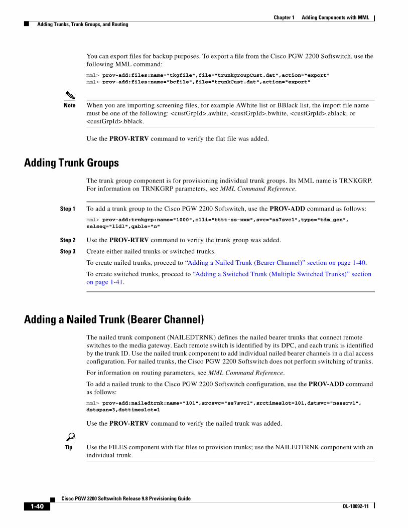
Chapter 1 Adding Components with MML Adding Trunks, Trunk Groups, and Routing
You can export files for backup purposes. To export a file from the Cisco PGW 2200 Softswitch, use the following MML command:
mml> prov-add:files:name="tkgfile",file="trunkgroupCust.dat",action="export"mml> prov-add:files:name="bcfile",file="trunkCust.dat",action="export"
Note When you are importing screening files, for example AWhite list or BBlack list, the import file name must be one of the following: <custGrpId>.awhite, <custGrpId>.bwhite, <custGrpId>.ablack, or <custGrpId>.bblack.
Use the PROV-RTRV command to verify the flat file was added.
Adding Trunk GroupsThe trunk group component is for provisioning individual trunk groups. Its MML name is TRNKGRP. For information on TRNKGRP parameters, see MML Command Reference.
Step 1 To add a trunk group to the Cisco PGW 2200 Softswitch, use the PROV-ADD command as follows:
mml> prov-add:trnkgrp:name="1000",clli="tttt-ss-xxx",svc="ss7svc1",type="tdm_gen",selseq="lidl",qable="n"
Step 2 Use the PROV-RTRV command to verify the trunk group was added.
Step 3 Create either nailed trunks or switched trunks.
To create nailed trunks, proceed to “Adding a Nailed Trunk (Bearer Channel)” section on page 1-40.
To create switched trunks, proceed to “Adding a Switched Trunk (Multiple Switched Trunks)” section on page 1-41.
Adding a Nailed Trunk (Bearer Channel)The nailed trunk component (NAILEDTRNK) defines the nailed bearer trunks that connect remote switches to the media gateway. Each remote switch is identified by its DPC, and each trunk is identified by the trunk ID. Use the nailed trunk component to add individual nailed bearer channels in a dial access configuration. For nailed trunks, the Cisco PGW 2200 Softswitch does not perform switching of trunks.
For information on routing parameters, see MML Command Reference.
To add a nailed trunk to the Cisco PGW 2200 Softswitch configuration, use the PROV-ADD command as follows:
mml> prov-add:nailedtrnk:name="101",srcsvc="ss7svc1",srctimeslot=101,dstsvc="nassrv1", dstspan=3,dsttimeslot=1
Use the PROV-RTRV command to verify the nailed trunk was added.
Tip Use the FILES component with flat files to provision trunks; use the NAILEDTRNK component with an individual trunk.
1-40Cisco PGW 2200 Softswitch Release 9.8 Provisioning Guide
OL-18092-11

Chapter 1 Adding Components with MML Adding Trunks, Trunk Groups, and Routing
Adding Multiple Nailed Trunks
To add multiple nailed trunks based on source service, source span, destination service, and destination span, use the PROV-ADD command as follows:
mml> prov-add:nailedtrnk:name="100",srcsvc="SC-1",dstsvc="PC-7-200-7",srcspan="0",dstspan="ffff",srctimeslot="1",dsttimeslot="4065",spansize=6
The previous command added the six nailed trunks shown in Table 1-1.
Use the PROV-RTRV:nailedtrnk:srcsvc=“sc-1” command to verify the nailed trunk groups were added.
Retrieving Multiple Nailed Trunks
To retrieve multiple nailed trunks, use the PROV-RTRV command as follows:
mml> prov-rtrv:nailedtrnk:srcsvc="sc-1"
Observe the screen to verify the command was successful.
Note Only one source service, destination service, source span, or destination span is allowed at a time.
Adding a Switched Trunk (Multiple Switched Trunks)The trunk (switched bearer channel) component is used for provisioning multiple switched trunks. Its MML name is SWITCHTRNK. For detailed information on trunk parameters, see MML Command Reference.
The following command adds the six switched trunks shown in Table 1-2.
To add switched trunks to the Cisco PGW 2200 Softswitch, use the PROV-ADD command as follows:
mml> prov-add:switchtrnk:name="1",trnkgrpnum="1000",span="ffff",cic=25,cu="gw1",spansize=6,endpoint="S0/DS1-1/6@li-5300-3"
Table 1-1 Nailed Trunk Command Result
Name SRCSVC SRCSPAN SRCTIMESLOT DSTSVC DSTSPAN DSTTIMESLOT
1 SC-1 0 1 PC-7-200-7 ffff 4065
2 SC-1 0 2 PC-7-200-7 ffff 4066
3 SC-1 0 3 PC-7-200-7 ffff 4067
4 SC-1 0 4 PC-7-200-7 ffff 4068
5 SC-1 0 5 PC-7-200-7 ffff 4069
6 SC-1 0 6 PC-7-200-7 ffff 4070
1-41Cisco PGW 2200 Softswitch Release 9.8 Provisioning Guide
OL-18092-11
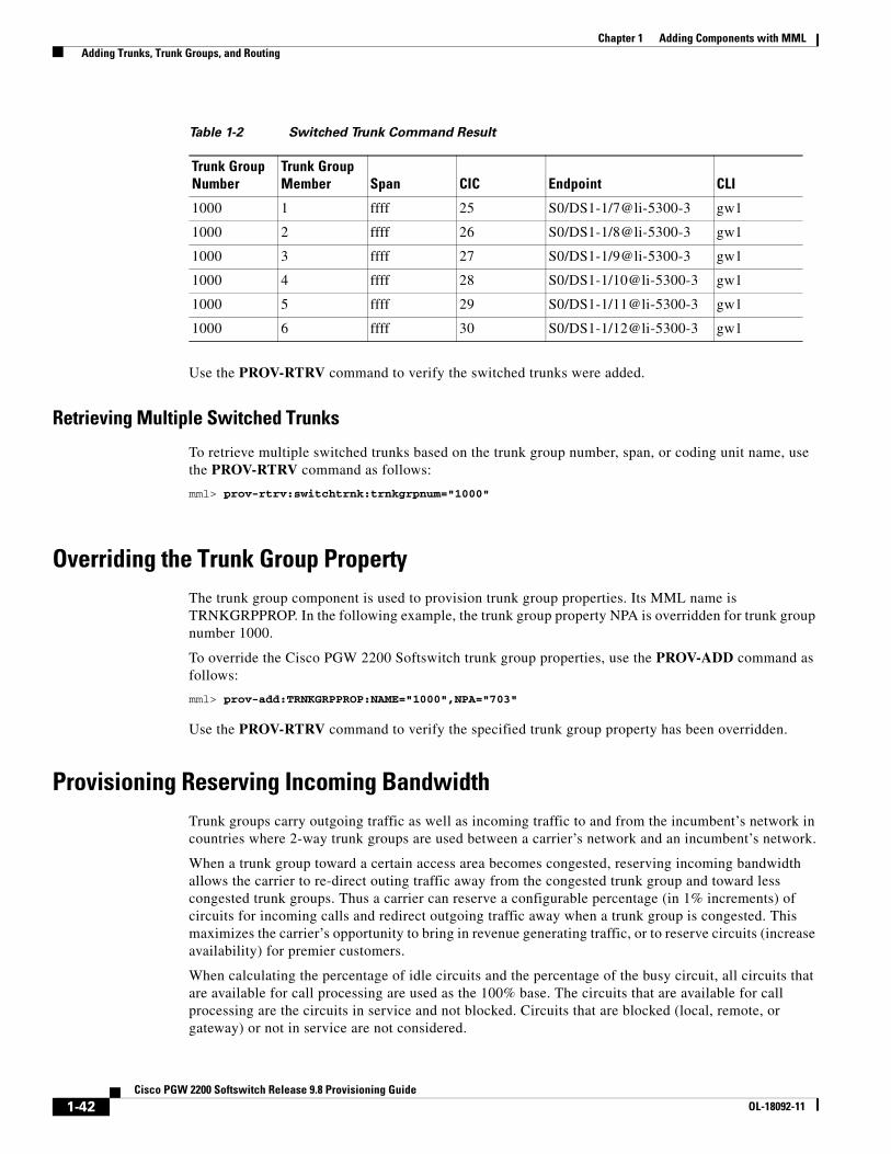
Chapter 1 Adding Components with MML Adding Trunks, Trunk Groups, and Routing
Use the PROV-RTRV command to verify the switched trunks were added.
Retrieving Multiple Switched Trunks
To retrieve multiple switched trunks based on the trunk group number, span, or coding unit name, use the PROV-RTRV command as follows:
mml> prov-rtrv:switchtrnk:trnkgrpnum="1000"
Overriding the Trunk Group PropertyThe trunk group component is used to provision trunk group properties. Its MML name is TRNKGRPPROP. In the following example, the trunk group property NPA is overridden for trunk group number 1000.
To override the Cisco PGW 2200 Softswitch trunk group properties, use the PROV-ADD command as follows:
mml> prov-add:TRNKGRPPROP:NAME="1000",NPA="703"
Use the PROV-RTRV command to verify the specified trunk group property has been overridden.
Provisioning Reserving Incoming BandwidthTrunk groups carry outgoing traffic as well as incoming traffic to and from the incumbent’s network in countries where 2-way trunk groups are used between a carrier’s network and an incumbent’s network.
When a trunk group toward a certain access area becomes congested, reserving incoming bandwidth allows the carrier to re-direct outing traffic away from the congested trunk group and toward less congested trunk groups. Thus a carrier can reserve a configurable percentage (in 1% increments) of circuits for incoming calls and redirect outgoing traffic away when a trunk group is congested. This maximizes the carrier’s opportunity to bring in revenue generating traffic, or to reserve circuits (increase availability) for premier customers.
When calculating the percentage of idle circuits and the percentage of the busy circuit, all circuits that are available for call processing are used as the 100% base. The circuits that are available for call processing are the circuits in service and not blocked. Circuits that are blocked (local, remote, or gateway) or not in service are not considered.
Table 1-2 Switched Trunk Command Result
Trunk Group Number
Trunk Group Member Span CIC Endpoint CLI
1000 1 ffff 25 S0/DS1-1/7@li-5300-3 gw1
1000 2 ffff 26 S0/DS1-1/8@li-5300-3 gw1
1000 3 ffff 27 S0/DS1-1/9@li-5300-3 gw1
1000 4 ffff 28 S0/DS1-1/10@li-5300-3 gw1
1000 5 ffff 29 S0/DS1-1/11@li-5300-3 gw1
1000 6 ffff 30 S0/DS1-1/12@li-5300-3 gw1
1-42Cisco PGW 2200 Softswitch Release 9.8 Provisioning Guide
OL-18092-11

Chapter 1 Adding Components with MML Adding Trunks, Trunk Groups, and Routing
For example, if there are 25 blocked circuits, 40 idle circuits, and 60 circuits with calls in progress (includes both incoming and outgoing), the total configured circuit is 125 in the trunk group, and the circuit available for call processing is 100. Therefore the percentage of the idle circuit is 40% (because 25 circuits are blocked and therefore not counted) and the percentage of the busy circuit is 60%. If the ResIncPerc property configured against the trunk group is 30%, no outgoing circuit is selected if the percentage of the idle circuit is less than 30%. When the percentage of the idle circuit is equal to or more than 30%, new outgoing calls are allowed for the trunk group.
Reserve a percentage of the available circuits (in service and not blocked) for incoming calls only when the number of idle and available circuits is equal to or below the reserved incoming percentage. If the ResIncPerc is set higher (that is reserving more incoming trunk groups), no calls are dropped to increase the current number of idle circuits, but no new outgoing calls are placed on the trunk group until the number of idle circuits drops below the new reserved incoming percentage value.
The call is routed using the alternative trunk group if the number of idle circuits is less than the configured ResIncPerc threshold and alternative routing trunk groups are specified. However, the call is dropped if no alternative routing trunk group is specified.
The range for this property is from 0 to 100%. The property value is saved during the routing data commit. The following MML command example sets the percentage of trunks in the routing trunk group that are reserved for incoming calls to 65%, if the trunk group name was 1000.
mml> prov-add:rttrnkgrp:name="1000",type="0",reattempts="5",queuing="1",cutthrough="1", resincperc="65"
Provisioning Bearer CapabilityThis section is used to configure the bearer capability for each trunk group.
To provision bearer capabilities to the Cisco PGW 2200 Softswitch configuration, use the PROV-ADD commands as follows:
Step 1 Use the following MML command to add the component and required parameters:
mml> prov-add:bearercap:name="bearer1",bearercap="12;05;31"
Step 2 Use the following MML command to add the component and required parameters:
mml> prov-add:siprttrnkgrp:name="2222",url="128.107.132.143",srvrr=0,sipproxyport=5060,version="2.0",cutthrough=1,extsupport=1,bearercapname="bearer1"
Step 3 Use the following MML command to add the component and required parameters:
mml> prov-add:rrttrnkgrp:name="1",type=1,reattempts=3,queuing=0,cutthrough=1,bearercapname="bearer1"
Step 4 Use the PROV-RTRV command to verify the bearer capability file was modified.
Enabling Overdecadic 32 Digit Operation for Number PortabilityEnabling the 32-digit overdecadic feature extends protocol-specific developments to all supported protocols for 32-digits and overdecadic digits (A through F). The feature supports number portability when the system receives and generates Cause 14. See Table 1-3 for a list of supported parameters per protocol family.
1-43Cisco PGW 2200 Softswitch Release 9.8 Provisioning Guide
OL-18092-11
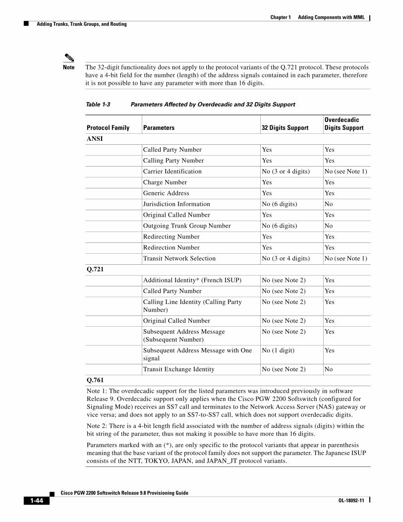
Chapter 1 Adding Components with MML Adding Trunks, Trunk Groups, and Routing
Note The 32-digit functionality does not apply to the protocol variants of the Q.721 protocol. These protocols have a 4-bit field for the number (length) of the address signals contained in each parameter, therefore it is not possible to have any parameter with more than 16 digits.
Table 1-3 Parameters Affected by Overdecadic and 32 Digits Support
Protocol Family Parameters 32 Digits SupportOverdecadic Digits Support
ANSI
Called Party Number Yes Yes
Calling Party Number Yes Yes
Carrier Identification No (3 or 4 digits) No (see Note 1)
Charge Number Yes Yes
Generic Address Yes Yes
Jurisdiction Information No (6 digits) No
Original Called Number Yes Yes
Outgoing Trunk Group Number No (6 digits) No
Redirecting Number Yes Yes
Redirection Number Yes Yes
Transit Network Selection No (3 or 4 digits) No (see Note 1)
Q.721
Additional Identity* (French ISUP) No (see Note 2) Yes
Called Party Number No (see Note 2) Yes
Calling Line Identity (Calling Party Number)
No (see Note 2) Yes
Original Called Number No (see Note 2) Yes
Subsequent Address Message (Subsequent Number)
No (see Note 2) Yes
Subsequent Address Message with One signal
No (1 digit) Yes
Transit Exchange Identity No (see Note 2) No
Q.761
Note 1: The overdecadic support for the listed parameters was introduced previously in software Release 9. Overdecadic support only applies when the Cisco PGW 2200 Softswitch (configured for Signaling Mode) receives an SS7 call and terminates to the Network Access Server (NAS) gateway or vice versa; and does not apply to an SS7-to-SS7 call, which does not support overdecadic digits.
Note 2: There is a 4-bit length field associated with the number of address signals (digits) within the bit string of the parameter, thus not making it possible to have more than 16 digits.
Parameters marked with an (*), are only specific to the protocol variants that appear in parenthesis meaning that the base variant of the protocol family does not support the parameter. The Japanese ISUP consists of the NTT, TOKYO, JAPAN, and JAPAN_JT protocol variants.
1-44Cisco PGW 2200 Softswitch Release 9.8 Provisioning Guide
OL-18092-11
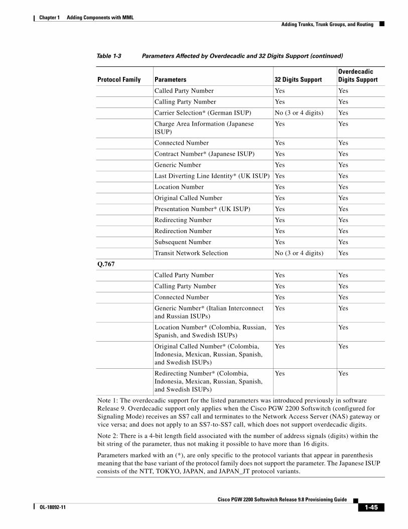
Chapter 1 Adding Components with MML Adding Trunks, Trunk Groups, and Routing
Called Party Number Yes Yes
Calling Party Number Yes Yes
Carrier Selection* (German ISUP) No (3 or 4 digits) Yes
Charge Area Information (Japanese ISUP)
Yes Yes
Connected Number Yes Yes
Contract Number* (Japanese ISUP) Yes Yes
Generic Number Yes Yes
Last Diverting Line Identity* (UK ISUP) Yes Yes
Location Number Yes Yes
Original Called Number Yes Yes
Presentation Number* (UK ISUP) Yes Yes
Redirecting Number Yes Yes
Redirection Number Yes Yes
Subsequent Number Yes Yes
Transit Network Selection No (3 or 4 digits) Yes
Q.767
Called Party Number Yes Yes
Calling Party Number Yes Yes
Connected Number Yes Yes
Generic Number* (Italian Interconnect and Russian ISUPs)
Yes Yes
Location Number* (Colombia, Russian, Spanish, and Swedish ISUPs)
Yes Yes
Original Called Number* (Colombia, Indonesia, Mexican, Russian, Spanish, and Swedish ISUPs)
Yes Yes
Redirecting Number* (Colombia, Indonesia, Mexican, Russian, Spanish, and Swedish ISUPs)
Yes Yes
Table 1-3 Parameters Affected by Overdecadic and 32 Digits Support (continued)
Protocol Family Parameters 32 Digits SupportOverdecadic Digits Support
Note 1: The overdecadic support for the listed parameters was introduced previously in software Release 9. Overdecadic support only applies when the Cisco PGW 2200 Softswitch (configured for Signaling Mode) receives an SS7 call and terminates to the Network Access Server (NAS) gateway or vice versa; and does not apply to an SS7-to-SS7 call, which does not support overdecadic digits.
Note 2: There is a 4-bit length field associated with the number of address signals (digits) within the bit string of the parameter, thus not making it possible to have more than 16 digits.
Parameters marked with an (*), are only specific to the protocol variants that appear in parenthesis meaning that the base variant of the protocol family does not support the parameter. The Japanese ISUP consists of the NTT, TOKYO, JAPAN, and JAPAN_JT protocol variants.
1-45Cisco PGW 2200 Softswitch Release 9.8 Provisioning Guide
OL-18092-11
Chapter 1 Adding Components with MML Adding Trunks, Trunk Groups, and Routing
To support up to 32 digits and overdecadic digits (A through F) in called and calling numbers across all supported protocols, set the TMaxDigits property (set on the sigpath) as follows:
mml> prov-add:sigsvcprop="ss7svc1",TMaxDigits="32"
Note MML targets of AWHITE, BWHITE, ABLACK, BBLACK, TERMTBL, ANUMDPSEL, and ACHGORIGIN only support the Calling Line Identity (CLI) up to 20 digits. The MML target of PORTTBL supports the called number and routing number up to 20 digits as well.
Provisioning the Generic LNP Protocol Enhancements: 32 Digits, Overdecadics, and Cause 14 Mapping Feature
With a provisioning session active, perform the following steps to provision the Generic LNP Protocol Enhancements: 32 Digits, Overdecadics, and Cause 14 Mapping Feature.
Step 1 Assuming the 32-digit overdecadic feature is disabled, dynamically change the OD32DigitSupport property for 32-digit and overdecadic support.mml> prov-add:trnkgrpprop:name="1000",OD32DigitSupport="1"
Note Setting the value of the OD32DigitSupport property to 0 disables overdecadic 32 digit support. The default property value is 1 (enabled).
Step 2 A response similar to the following is returned:Media Gateway Controller - MGC-03 2003-02-17 14:25:56
M COMPLD"trnkgrp"
Redirection Number* (Colombia, Indonesia, Mexican, Russian, Spanish, and Swedish ISUPs)
Yes Yes
Subsequent Number Yes Yes
Transit Network Selection* (Colombia and Mexican ISUPs)
No (3 or 4 digits) Yes
Table 1-3 Parameters Affected by Overdecadic and 32 Digits Support (continued)
Protocol Family Parameters 32 Digits SupportOverdecadic Digits Support
Note 1: The overdecadic support for the listed parameters was introduced previously in software Release 9. Overdecadic support only applies when the Cisco PGW 2200 Softswitch (configured for Signaling Mode) receives an SS7 call and terminates to the Network Access Server (NAS) gateway or vice versa; and does not apply to an SS7-to-SS7 call, which does not support overdecadic digits.
Note 2: There is a 4-bit length field associated with the number of address signals (digits) within the bit string of the parameter, thus not making it possible to have more than 16 digits.
Parameters marked with an (*), are only specific to the protocol variants that appear in parenthesis meaning that the base variant of the protocol family does not support the parameter. The Japanese ISUP consists of the NTT, TOKYO, JAPAN, and JAPAN_JT protocol variants.
1-46Cisco PGW 2200 Softswitch Release 9.8 Provisioning Guide
OL-18092-11
Chapter 1 Adding Components with MML Adding Trunks, Trunk Groups, and Routing
Step 3 Commit the provisioning session changes.mml> prov-dply
Verifying the Generic LNP Protocol Enhancements: 32 Digits, Overdecadics, and Cause 14 Mapping Feature
After you have provisioned the Generic LNP Protocol Enhancements: 32 Digits, Overdecadics, and Cause 14 Mapping Feature, perform the following steps to verify its setting.
Step 1 With an provisioning session active, use prov-rtrv:trnkgrpprop:name=”1000” to verify the trunk group property is correctly provisioned.mml> prov-rtrv:trnkgrpprop:name="1000"
Step 2 A response, similar to the following, is returned:
Media Gateway Controller - MGC-03 2003-02-17 14:27:52M RTRV"session=trnkgrpprop"/*BOrigStartIndex = 0BTermStartIndex = 1CarrierIdentity = 0CLLI = STEVECompressionType = 1CotPercentage = 0CustGrpId = 0000EchoCanRequired = 0ExtCOT = LoopGLARE = 0Npa = 0RingNoAnswer = 255000SatelliteInd = 0ScreenFailAction = 0•••OD32DigitSupport = 1 */;
Provisioning SUBSCRIBE/NOTIFY MethodsThe procedures for provisioning the SUBSCRIBE/NOTIFY methods are in the following sections:
• Enabling SUBSCRIBE/NOTIFY Methods, page 1-47
• Disabling SUBSCRIBE/NOTIFY Methods, page 1-48
Enabling SUBSCRIBE/NOTIFY Methods
Use the following steps to enable the SUBSCRIBE/NOTIFY methods:
Step 1 Start a provisioning session.
1-47Cisco PGW 2200 Softswitch Release 9.8 Provisioning Guide
OL-18092-11

Chapter 1 Adding Components with MML Adding Trunks, Trunk Groups, and Routing
Step 2 Enable the SUBSCRIBE/NOTIFY methods on a SIP trunk group with the following command:
mml> prov-ed:trnkgrpprop:name="trnkgrpnum",custgrpid="grpid",SubscribeNotifySupport=1
For example, to enable the SUBSCRIBE/NOTIFY methods on a SIP trunk group called 3333, you would enter the following command:
mml> prov-ed:trnkgrpprop:name="3333",custgrpid="1111",SubscribeNotifySupport=1
Step 3 If there are no other components that you need to provision, end your provisioning session.
Disabling SUBSCRIBE/NOTIFY Methods
Use the following steps to disable the SUBSCRIBE/NOTIFY methods:
Step 1 Start a provisioning session.
Step 2 Disable the SUBSCRIBE/NOTIFY methods on a SIP trunk group with the following command:
mml> prov-ed:trnkgrpprop:name="trnkgrpnum",custgrpid="grpid",SubscribeNotifySupport=0
For example, to disable the SUBSCRIBE/NOTIFY methods on a SIP trunk group called 3333, you would enter the following command:
mml> prov-ed:trnkgrpprop:name="3333",custgrpid="1111",SubscribeNotifySupport=0
Step 3 If there are no other components that you need to provision, end your provisioning session.
Provisioning Unsolicited NotificationsThe procedures for provisioning unsolicited notifications are in the following sections:
• Enabling Unsolicited Notifications, page 1-48
• Disabling Unsolicited Notifications, page 1-49
Enabling Unsolicited Notifications
Use the following steps to enable the Unsolicited NOTIFY method for SIP DTMF digits by the Cisco PGW 2200 Softswitch:
Step 1 Start a provisioning session.
Step 2 Enable unsolicited notifications on a SIP trunk group using the following command:
mml> prov-ed:trnkgrpprop:name="trnkgrpnum",custgrpid="grpid",UnsolicitedNotifyMethod=1
For example, to enable unsolicited notifications on a SIP trunk group called 3333, you would enter the following command:
mml> prov-ed:trnkgrpprop:name="3333",custgrpid="1111",UnsolicitedNotifyMethod=1
1-48Cisco PGW 2200 Softswitch Release 9.8 Provisioning Guide
OL-18092-11

Chapter 1 Adding Components with MML Adding Trunks, Trunk Groups, and Routing
Step 3 If there are no other components that you need to provision, end your provisioning session.
Disabling Unsolicited Notifications
Use the following steps to disable the Unsolicited NOTIFY method for SIP DTMF digits by the Cisco PGW 2200 Softswitch:
Step 1 Start a provisioning session.
Step 2 Disable unsolicited notifications on a SIP trunk group using the following command:
mml> prov-ed:trnkgrpprop:name="trnkgrpnum",custgrpid="grpid",UnsolicitedNotifyMethod=0
For example, to disable unsolicited notifications on a SIP trunk group called 3333, you would enter the following command:
mml> prov-ed:trnkgrpprop:name="3333",custgrpid="1111",UnsolicitedNotifyMethod=0
Step 3 If there are no other components that you need to provision, end your provisioning session.
Provisioning Subscription DurationThe procedures for provisioning the duration data for subscriptions are in the following sections:
• Provisioning Minimum Subscription Duration for Telephony Event, page 1-49
• Provisioning Maximum Duration for SUBSCRIBE, page 1-50
Provisioning Minimum Subscription Duration for Telephony Event
Use the following steps to define the minimum duration for which a telephony event can exist before it can be re-subscribed:
Step 1 Start a provisioning session.
Step 2 Set the minimum duration of a telephony event on a SIP trunk group:
mml> prov-ed:trnkgrpprop:name="trnkgrpnum",custgrpid="grpid", MinEventSubscribeDuration=minsub
For example, to provision a telephony event to last a minimum of 200 ms on a SIP trunk group called 3333, you would enter the following command:
mml> prov-ed:trnkgrpprop:name="3333",custgrpid="1111",MinEventSubscribeDuration=200
Step 3 If there are no other components that you need to provision, end your provisioning session.
1-49Cisco PGW 2200 Softswitch Release 9.8 Provisioning Guide
OL-18092-11

Chapter 1 Adding Components with MML Adding Trunks, Trunk Groups, and Routing
Provisioning Maximum Duration for SUBSCRIBE
Use the following steps to define the maximum duration for which the subscription can exist before it needs a re-subscription:
Step 1 Start a provisioning session.
Step 2 Set the maximum duration time for a subscription on a SIP trunk group:
mml> prov-ed:trnkgrpprop:name="trnkgrpnum",custgrpid="grpid", MaxSubscriptionDuration=maxsub
For example, to provision a subscription to last a maximum of 3600 seconds on a SIP trunk group called 3333, you would enter the following command:
mml> prov-ed:trnkgrpprop:name="3333",custgrpid="1111",MaxSubscriptionDuration=3600
Step 3 If there are no other components that you need to provision, end your provisioning session.
Enabling and Disabling Information Extraction from SDPThis section describes procedures required to enable or disable extracting information from the SD P.
Enabling Support of Information Extraction from Sockets Direct Protocol (SDP)
Use the following steps to enable extracting SDP information for billing purposes:
Step 1 Start a provisioning session.
Step 2 Enter the following command to enable SDP information extraction:
mml> prov-ed:trnkgrpprop:name="trnk_num",populateSDPInfoInCDR="1"
Where: trnk_num—The number of the trunk to be modified.
For example, to enable SDP information extraction on a trunk group called 5000, you would enter the following command:
mml> prov-add:trnkgrpprop:name="5000",populateSDPInfoInCDR="1"
Step 3 Repeat Step 2 for each trunk group you want to modify.
Disabling Support of Information Extraction from SDP
Use the following steps to disable extracting SDP information for billing purposes:
Step 1 Start a provisioning session.
Step 2 Enter the following command to disable SDP information extraction:
mml> prov-ed:trnkgrpprop:name="trnk_num",populateSDPInfoInCDR="0"
Where: trnk_num—The number of the trunk to be modified.
1-50Cisco PGW 2200 Softswitch Release 9.8 Provisioning Guide
OL-18092-11

Chapter 1 Adding Components with MML Adding Trunks, Trunk Groups, and Routing
For example, to disable SDP information extraction on a trunk group called 5000, you would enter the following command:
mml> prov-add:trnkgrpprop:name="5000",populateSDPInfoInCDR="0"
Step 3 Repeat Step 2 for each trunk group you want to modify.
Provisioning Routing This section explains how to provision routing. The provisioned routing values enable the system to perform route analysis, which identifies the path for bearer traffic to travel from the Cisco PGW 2200 Softswitch to the adjacent switch.
This section includes the following topics:
• Configuring Routing Trunk Groups, Routing Trunks, and Route Lists, page 1-51
• Provisioning Weighted Trunk Group with the RTTRNK Component, page 1-52
• Optimizing PGW-to-ITP Routing with MAP Query, page 1-53
Configuring Routing Trunk Groups, Routing Trunks, and Route Lists
Three components are necessary to provision routing, routing trunk groups, routing trunks, and route lists. Their MML names are RTTRNKGRP, RTTRNK, and RTLIST.
Tip The following examples listed illustrate the syntax and sequence of these commands. For detailed descriptions of the individual command parameters, see MML Command Reference.
To add routing files to Cisco PGW 2200 Softswitch, use the PROV-ADD commands as follows:
Step 1 Use the following MML command to add a routing trunk group:
mml> prov-add:rttrnkgrp:name="501",type=7,reattempts=1,queuing=0,cutthrough=2
Step 2 Use the following MML command to add a route and associate the trunk group with the route:
mml> prov-add:rttrnk:name="rt513",trnkgrpnum=513
Note To provision weighted trunk groups, see the “Provisioning Weighted Trunk Group with the RTTRNK Component” section on page 1-52.
Step 3 Use the following MML command to add a route list and add the route in the route list:
mml> prov-add:rtlist:name="rtlist501",rtname="rt501"
Note Route lists are referred to as route groups in VSPT.
Step 4 Use the PROV-RTRV command to verify the routing files were added.
1-51Cisco PGW 2200 Softswitch Release 9.8 Provisioning Guide
OL-18092-11

Chapter 1 Adding Components with MML Adding Trunks, Trunk Groups, and Routing
Tip All the route lists, route trunks, and route trunk groups information can be retrieved by using the prov-rtrv:rtlist:“all” command. The all option cannot be used with other parameters.
Provisioning Weighted Trunk Group with the RTTRNK Component
Weighted trunk group-based routing allows you to use the same trunk group multiple times in the same route when random distribution is enabled.
The DISTRIB route parameter determines whether the Cisco PGW 2200 Softswitch uses the random distribution when selecting trunk groups for the route. DISTRIB uses the following values:
• OFF—The Cisco PGW 2200 Softswitch uses sequential selection to choose trunk groups in the route. This is the default value.
• ON—The Cisco PGW 2200 Softswitch uses random selection to choose trunk groups in the route. This setting is useful if you need to balance the choice of trunk groups across equipment.
You can use the WEIGHTEDTG parameter on the rttrnk to specify if whether weighted trunk group-based routing is enabled. The parameter values are ON or OFF (default).
Use the following guidelines when modifying weighted trunk group parameters:
• If weighted trunk group-based routing is enabled at the route trunk level, any connected route list must have random distribution enabled.
• If weighted trunk group-based routing is enabled at the route trunk level, you can add the same route trunk group to the route trunk multiple times. If weighted trunk group based-routing is disabled at the route trunk, you cannot add the same route trunk group to the route trunk multiple times.
• If you connect a route trunk group to a route trunk more than once, you cannot disable weighted trunk group-based routing on the route trunk group.
• If you connect a route list to a route trunk with weighted trunk group-based routing enabled, you cannot change the route list DISTRIB parameter to OFF.
• If a route trunk has weighted trunk group-based routing enabled, the nexttrkgrp parameter is not supported.
• If you delete a route trunk group from a route trunk that has multiple route trunk groups of the same value, the command deletes only the first route trunk group in the list. You must repeat the command to delete all route trunk groups with the same name.
• Do not assign more than 100 route trunk groups to a route trunk.
• The Cisco PGW 2200 Softswitch performs weighted trunk group-based routing once you have added the same route trunk group to a route trunk multiple times.
The following MML example creates route trunk called route1 that has 25% of the calls on trunk group 1111 and 75% of the calls on trunk group 2222.
prov-sta::srcver="new",dstver="test",confirmprov-add:rttrnkgrp:name="1111",type=0prov-add:rttrnkgrp:name="2222",type=0,reattempts=5,queuing=2,cutthrough=3prov-add:rttrnkgrp:name="3333",type=0,reattempts=1,queuing=1,cutthrough=1prov-add:rttrnk:name="route1",trnkgrpnum=1111,weightedtg="ON"prov-ed:rttrnk:name="route1",trnkgrpnum=2222,weightedtg="ON"prov-ed:rttrnk:name="route1",trnkgrpnum=2222prov-ed:rttrnk:name="route1",trnkgrpnum=2222prov-add:rttrnk:name="route2",trnkgrpnum=3333,weightedtg="OFF"prov-add:rttrnk:name="route3",trnkgrpnum=2222,weightedtg="OFF"prov-add:rtlist:name="one",rtname="route2",distrib="OFF"
1-52Cisco PGW 2200 Softswitch Release 9.8 Provisioning Guide
OL-18092-11
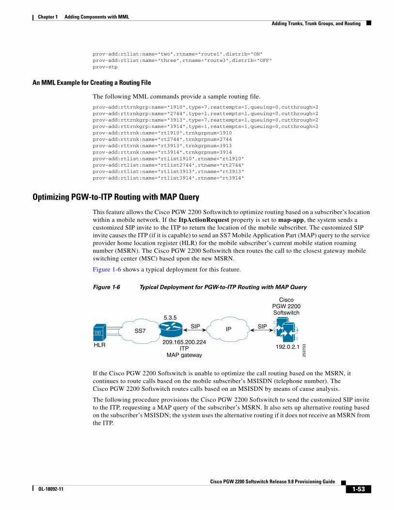
Chapter 1 Adding Components with MML Adding Trunks, Trunk Groups, and Routing
prov-add:rtlist:name="two",rtname="route1",distrib="ON"prov-add:rtlist:name="three",rtname="route3",distrib="OFF"prov-stp
An MML Example for Creating a Routing File
The following MML commands provide a sample routing file.
prov-add:rttrnkgrp:name="1910",type=7,reattempts=1,queuing=0,cutthrough=2prov-add:rttrnkgrp:name="2744",type=1,reattempts=1,queuing=0,cutthrough=2prov-add:rttrnkgrp:name="3913",type=7,reattempts=1,queuing=0,cutthrough=2prov-add:rttrnkgrp:name="3914",type=1,reattempts=1,queuing=0,cutthrough=2prov-add:rttrnk:name="rt1910",trnkgrpnum=1910prov-add:rttrnk:name="rt2744",trnkgrpnum=2744prov-add:rttrnk:name="rt3913",trnkgrpnum=3913prov-add:rttrnk:name="rt3914",trnkgrpnum=3914prov-add:rtlist:name="rtlist1910",rtname="rt1910"prov-add:rtlist:name="rtlist2744",rtname="rt2744"prov-add:rtlist:name="rtlist3913",rtname="rt3913"prov-add:rtlist:name="rtlist3914",rtname="rt3914"
Optimizing PGW-to-ITP Routing with MAP Query
This feature allows the Cisco PGW 2200 Softswitch to optimize routing based on a subscriber’s location within a mobile network. If the ItpActionRequest property is set to map-app, the system sends a customized SIP invite to the ITP to return the location of the mobile subscriber. The customized SIP invite causes the ITP (if it is capable) to send an SS7 Mobile Application Part (MAP) query to the service provider home location register (HLR) for the mobile subscriber’s current mobile station roaming number (MSRN). The Cisco PGW 2200 Softswitch then routes the call to the closest gateway mobile switching center (MSC) based upon the new MSRN.
Figure 1-6 shows a typical deployment for this feature.
Figure 1-6 Typical Deployment for PGW-to-ITP Routing with MAP Query
If the Cisco PGW 2200 Softswitch is unable to optimize the call routing based on the MSRN, it continues to route calls based on the mobile subscriber’s MSISDN (telephone number). The Cisco PGW 2200 Softswitch routes calls based on an MSISDN by means of cause analysis.
The following procedure provisions the Cisco PGW 2200 Softswitch to send the customized SIP invite to the ITP, requesting a MAP query of the subscriber’s MSRN. It also sets up alternative routing based on the subscriber’s MSISDN; the system uses the alternative routing if it does not receive an MSRN from the ITP.
SS7 IP
5.3.5
SIP
209.165.200.224ITP
MAP gateway
SIP
CiscoPGW 2200Softswitch
192.0.2.1HLR
2537
03
1-53Cisco PGW 2200 Softswitch Release 9.8 Provisioning Guide
OL-18092-11

Chapter 1 Adding Components with MML Adding Trunks, Trunk Groups, and Routing
Step 1 Create two trunk groups, one for the MSRN (when the ITP returns an MSRN), and a second trunk group for the MSISDN (when the ITP does not return an MSRN). In the following examples, trunk group 907 is for the MSRN and trunk group 1001 is for the MSISDN (or if routing on trunk group 907 fails):
mml> prov-add:rttrnk:weightedTG="OFF",name="rg907",trnkgrpnum=907mml> prov-ed:rttrnk:name="rg907",trnkgrpnum=1001mml> prov-add:rtlist:name="rlst907",rtname="rg907",distrib="OFF"
Step 2 Enter the following command to enable the MAP request on the trunk group for the MSRN:
mml> prov-ed:trnkgrpprop:name="xxx",ItpActionRequest="map-app"
Note If you need to disable the MAP request, enter the following commandProv-dlt:trnkgrpprop:name="xxx", "ItpActionRequest"
Step 3 (Optional) Advance the trunk for failed calls using the following MML commands:
mml> numan-add:resultset:custgrpid="DP00",name="tgadvset"mml> numanadd:resulttable:custgrpid="DP00",name="tgadvset",resulttype="RETRY_ACTION", dw1="tgadvance",setname="tgadvset"mml> numan-ed:cause:custgrpid="DP00",causevalue=176,setname="tgadvset"
/* The value for the internal cause code, IC_ITP_QUERY_FAIL, is 176. */
Step 4 (Optional) Switch to new a new dial plan for failed calls using the following MML commands:
mml> numan-add:dialplan:custgrpid="DP01",OVERDEC="NO"mml> numan-add:resultset:custgrpid="DP01",name="rset-1"mml> numan-add:resulttable:custgrpid="DP01",name="rtab-1",resulttype="ROUTE", dw1="rtlist1",setname="rset-1"mml> numan-add:bdigtree:custgrpid="DP01",callside="originating",digitstring="12", setname="rset-1"
mml> numan-add:dpsel:custgrpid="DP00", newdp="DP01"mml> numan-add:resultset:custgrpid="DP00",name="SwToDP01"mml> numan-add:resulttable:custgrpid="DP00",name="SwitchDP1",resulttype="NEW_DIALPLAN", dw1="DP01",dw2="2",setname="SwToDP01"mml> numan-ed:cause:custgrpid="DP00",causevalue=176,setname="SwToDP01"
/* The value for the internal cause code, IC_ITP_QUERY_FAIL, is 176. */
The provisioning examples for ITP as a MAP proxy for this feature are as follows:
cs7 variant itucs7 point-code 5.3.5
interface ethernet 0/0ip address 209.165.200.224 255.255.255.224
cs7 mapua SIP_MAP_GW sipclient 192.0.2.1map-source-addr digits 1234567890 tt 0 gti 2gsm-send-routing-info version 2
invoke-timer 20
For more information on the ITP provisioning, see the “Implementing a PGW SIP MAP Gateway” section in Cisco IP Transfer Point (ITP) in IOS Software Release 12.4(I5)SW4 at
http://www.cisco.com/en/US/docs/wireless/itp/itp_12_2_18_ipx/PDFs/12415sw4.pdf
1-54Cisco PGW 2200 Softswitch Release 9.8 Provisioning Guide
OL-18092-11
Chapter 1 Adding Components with MML Adding Trunks, Trunk Groups, and Routing
You can use the following three commands to monitor ITP for this feature:
• Display SIP MAP gateway information.
show cs7 mapua statistics [name of the MAP UA]
• Display Cisco IOS SIP stack statistics.
show cs7 sip statistics
• Debug the MAP gateway function.
debug cs7 map-ua {all | error | packet | api}
Provisioning Least Cost RoutingWhen provisioning the routing components in the Cisco PGW 2200 Softswitch, it is possible to modify and change the order of trunk groups (rttrnkgrp) in a route (rttrnk), or routes (rttrnk) in a route list (rtlist). These commands can be very useful in dynamically adjusting Least Cost Routing.
Note The inserted route or trnkgrp appears before the next trunk group name.
The following MML command examples show a route defined with four trunk groups:
mgc4 mml> prov-rtrv:rttrnk:name="routea" MGC-01 - Media Gateway Controller 2002-02-23 01:16:43.381 GMTM RTRV "session=nexttrnkgrp:rttrnk" /* routeName---------routea
trunkGroup nextTrunkGroup ---------- -------------- 2000 3000 3000 4000 4000 5000 5000 */
If you discover you are required to change the trunk group order (that is, trunk group 5000 is the best value), start a provisioning session and use the following MML commands:
mgc4 mml> prov-ed:rttrnk:name="routea",trnkgrpnum=5000,nexttrkgrp=2000 MGC-01 - Media Gateway Controller 2002-02-23 01:17:00.944 GMTM COMPLD "rttrnk" ;mgc4 mml> prov-rtrv:rttrnk:name="routea" MGC-01 - Media Gateway Controller 2002-02-23 01:17:03.039 GMTM RTRV "session=nexttrnkgrp:rttrnk" /* routeName---------routea
trunkGroup nextTrunkGroup
1-55Cisco PGW 2200 Softswitch Release 9.8 Provisioning Guide
OL-18092-11
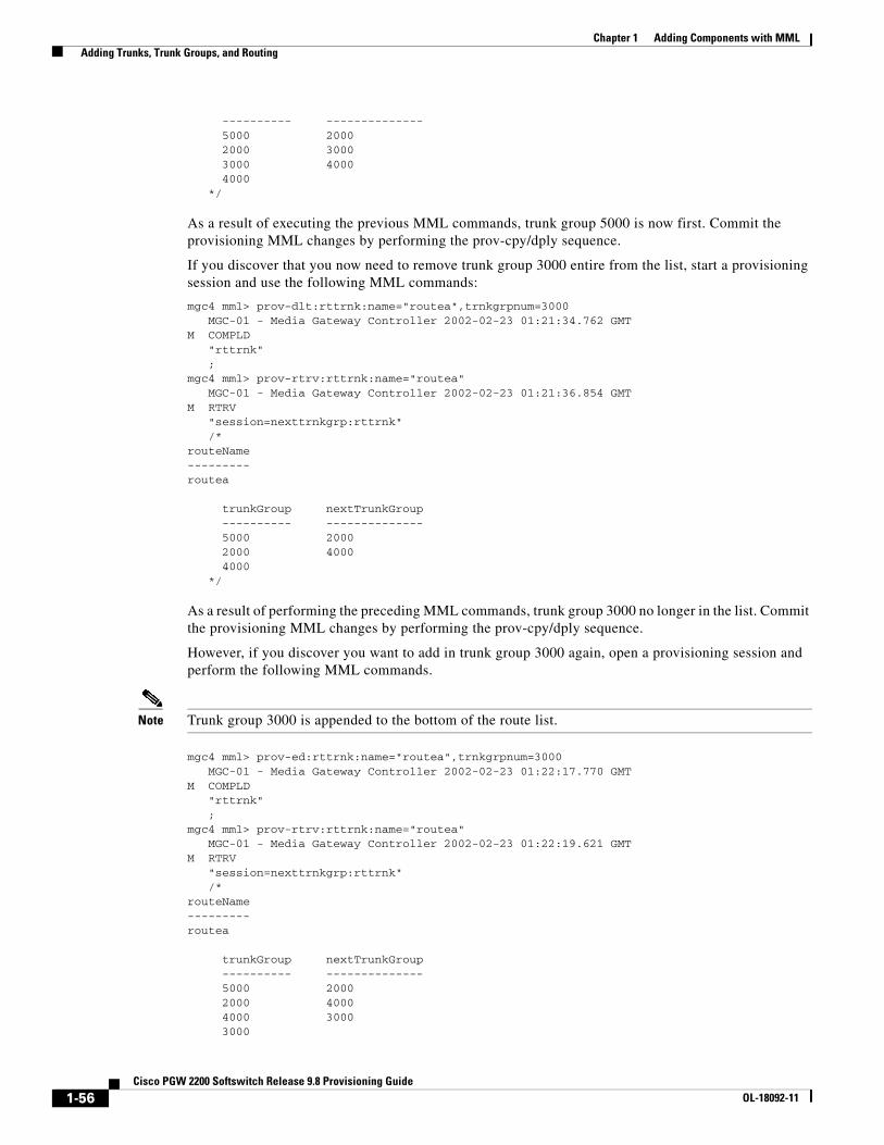
Chapter 1 Adding Components with MML Adding Trunks, Trunk Groups, and Routing
---------- -------------- 5000 2000 2000 3000 3000 4000 4000 */
As a result of executing the previous MML commands, trunk group 5000 is now first. Commit the provisioning MML changes by performing the prov-cpy/dply sequence.
If you discover that you now need to remove trunk group 3000 entire from the list, start a provisioning session and use the following MML commands:
mgc4 mml> prov-dlt:rttrnk:name="routea",trnkgrpnum=3000 MGC-01 - Media Gateway Controller 2002-02-23 01:21:34.762 GMTM COMPLD "rttrnk" ;mgc4 mml> prov-rtrv:rttrnk:name="routea" MGC-01 - Media Gateway Controller 2002-02-23 01:21:36.854 GMTM RTRV "session=nexttrnkgrp:rttrnk" /* routeName---------routea
trunkGroup nextTrunkGroup ---------- -------------- 5000 2000 2000 4000 4000 */
As a result of performing the preceding MML commands, trunk group 3000 no longer in the list. Commit the provisioning MML changes by performing the prov-cpy/dply sequence.
However, if you discover you want to add in trunk group 3000 again, open a provisioning session and perform the following MML commands.
Note Trunk group 3000 is appended to the bottom of the route list.
mgc4 mml> prov-ed:rttrnk:name="routea",trnkgrpnum=3000 MGC-01 - Media Gateway Controller 2002-02-23 01:22:17.770 GMTM COMPLD "rttrnk" ;mgc4 mml> prov-rtrv:rttrnk:name="routea" MGC-01 - Media Gateway Controller 2002-02-23 01:22:19.621 GMTM RTRV "session=nexttrnkgrp:rttrnk" /* routeName---------routea
trunkGroup nextTrunkGroup ---------- -------------- 5000 2000 2000 4000 4000 3000 3000
1-56Cisco PGW 2200 Softswitch Release 9.8 Provisioning Guide
OL-18092-11

Chapter 1 Adding Components with MML Adding Trunks, Trunk Groups, and Routing
*/ ;mgc4 mml>
If, after adding trunk group 3000, you want to make it the primary choice trunk group, open a provisioning session and perform the following MML commands:
mgc4 mml> prov-ed:rttrnk:name="routea",trnkgrpnum=3000,nexttrkgrp=5000 MGC-01 - Media Gateway Controller 2002-02-23 01:47:24.965 GMTM COMPLD "rttrnk" ;mgc4 mml> prov-rtrv:rttrnk:name="routea" MGC-01 - Media Gateway Controller 2002-02-23 01:47:26.551 GMTM RTRV "session=nexttrnkgrp:rttrnk" /* routeName---------routea
trunkGroup nextTrunkGroup ---------- -------------- 3000 5000 5000 2000 2000 4000 4000 */ ;mgc4 mml>
Provisioning Routing Based on Redirecting NumberThe Cisco PGW 2200 Softswitch can do number analysis and route selection based on the redirecting number contained in the H.323 Setup or SIP Invite message.
The feature is used to route a call from a PBX to its closest local or national TDM switch based on the redirecting number. This feature ensures that calls forwarded from one country to another use the correct dial plan by routing based on the redirecting number rather than the original calling party number.
To provision routing based on redirecting number, perform the following procedure:
Step 1 Add dial plans dp00, dp 01, and dp02 by using the following MML command in an open provisioning session:
mml> numan-add:dialplan:custgrpid="DP00",OVERDEC="NO"mml> numan-add:dialplan:custgrpi="DP01",OVERDEC="NO"mml> numan-add:dialplan:custgrpi="DP02",OVERDEC="NO"
Step 2 Add a SIP signaling service and a SIP link:
mml> prov-add:sippath:NAME="sip-path",DESC="SIP path",MDO="IETF_SIP"mml> prov-add:siplnk:NAME="sip-link",DESC="SIP link",SVC="sip-path",IPADDR="IP_Addr2", PORT=5060,PRI=1
Step 3 Add an outgoing SIP trunk group:
mml> prov-add:trnkgrp:NAME="3", CLLI="sip-path", SVC="sip-path", TYPE="IP_SIP", SELSEQ="LIDL", QABLE="N"mml> prov-add:trnkgrpprop:name="3",custgrpid="DP01",MGCdomain="10.0.57.90",
1-57Cisco PGW 2200 Softswitch Release 9.8 Provisioning Guide
OL-18092-11

Chapter 1 Adding Components with MML Creating Profiles
mgcsipversion="sip/2.0", Localport="5060"mml> prov-add:siprttrnkgrp:name="3",url="10.0.20.112",srvrr=0,sipproxyport=5060, version="2.0",cutthrough=1,extsupport=1
mml> prov-add:rttrnk:name="rg3",trnkgrpnum=3mml> prov-add:rtlist:name="rlst3",rtname="rg3"
Step 4 Add an outgoing EISUP trunk group using the existing ISUP signaling service, eisup-hsi:
mml> prov-add:trnkgrp:name="9700",type="IP",svc="eisup-hsi",clli="hsi-a"mml> prov-add:rttrnkgrp:name="9700",type=4,reattempts=3,queuing=0,cutthrough=1,resincperc=0mml> prov-add:rttrnk:weightedTG="OFF",name="eisup-rt9700",trnkgrpnum=9700mml> prov-add:rtlist:name="eisup-rtlist-4",rtname="eisup-rt9700",distrib="OFF"
Step 5 Add a dial plan selection, a digit modification, result sets and results in dial plan dp00:
mml> numan-add:dpsel:custgrpid="DP00",newdp="DP01"mml> numan-add:digmodstring:custgrpid="DP00", name="digmoda", digstring="456222"
mml> numan-add:resultset:custgrpid="DP00",name="SwToDP1"mml> numan-add:resulttable:custgrpid="DP00", name="moda", resulttype="AMODDIG", dw1="1", dw2="6", dw3="digmoda", setname="SwToDP1"mml> numan-add:resulttable:custgrpid="DP00",name="SwitchDP1",resulttype="NEW_DIALPLAN", dw1="DP01",dw2="0",setname="SwToDP1"
mml> numan-add:resultset:custgrpid="DP00",name="SwToDP2"mml> numan-add:resulttable:custgrpid="DP00",name="SwitchDP2",resulttype="NEW_DIALPLAN", dw1="DP02",dw2="0",setname="SwToDP2"
mml> numan-add:adigtree:custgrpid="DP00",callside="originating",digitstring="476", setname="SwToDP1"mml> numan-add:adigtree:custgrpid="DP00",callside="originating",digitstring="40", setname="SwToDP2"
Step 6 Set the value of the RedirnumForAnalysis property to 1 for SIP ingress trunk groups:
mml> prov-add:sigsvcprop:name="sip-path",redirnumforanalysis="1"
Note Value 1 for the RedirnumForAnalysis property indicates using the redirecting number as A number for generic analysis with RMODDIG disabled. For more information on this property, see Chapter 6, “Properties” of MML Command Reference.
Step 7 Set the value of the RedirnumForAnalysis property to 1 for H.323 ingress trunk groups:
mml> prov-add:sigsvcprop:name="eisup-hsi",redirnumforanalysis="1"
Step 8 If there are no other components that you need to provision, end your provisioning session.
Creating ProfilesThis section describes the types of profiles you can create on the Cisco PGW 2200 Softswitch. Profiles allow you to create a customized set of properties that you can apply to one or more trunk groups.
Note Properties override individual trunk group settings.
1-58Cisco PGW 2200 Softswitch Release 9.8 Provisioning Guide
OL-18092-11

Chapter 1 Adding Components with MML Creating Profiles
This section covers the following topics:
• Provisioning SIP and EISUP Profiles, page 1-59—Profiles for SIP and EISUP trunk groups. This topic also includes examples of the common profiles (COMMONPROFILE). A common profile is an extension of SIP and EISUP profiles that allows you to create a set of provisioning properties for multiple protocols. Common profiles can contain any of the properties present in other profile types.
Note SIP and EISUP profile properties replace SIP and EISUP trunk group properties in Cisco PGW 2200 Softswitch Release 9.8(1).
• Provisioning Domain Profiles and Domain Names, page 1-62—Profiles for SIP inbound or outbound domains.
• Provisioning GRprofile, page 1-64—Profiles for non-IP trunk groups. You can also attach these profiles to a SIPPROFILE or EISUPPROFILE.
• Provisioning ISUP Timer Profiles, page 1-65—Profiles of ISUP timers for signaling services. You can attach these profiles to an SS7 sigpath.
• Provisioning Trunk Group Profiles, page 1-66—Profiles for customizing call behavior on trunk groups.
• Assigning Profiles to Trunk Groups, page 1-66—You can assign profiles that you created to trunk groups.
• Provisioning ATM Profiles, page 1-67—Profiles for managing the network Service Level Agreement.
• Provisioning Gateway Pools and Gateway Pool Profiles for H.248 Components, page 1-68—The gateway pool profile (GWPOOLPROFILE) defines the capability set for a set of gateways (gateway pools). The capabilities include playing tones and announcements, transcoding, and processing DTMF.
Assemble the information you need to provision profiles by filling in the following planning worksheets:
• Table 1-36, SIP and EISUP Profiles Worksheet Example
• Table 1-37, Common Profiles Worksheet Example
• Table 1-38, Domain Profile Worksheet Example
• Table 1-39, Trunk Group Profile Assignments Worksheet Example
• Table 1-43, Gateway Pool Worksheet Example
Provisioning SIP and EISUP ProfilesUse the commands presented in this section to provision SIP and EISUP profiles.
Note For information on provisioning SIP components, see the “Adding SIP Components” section on page 1-71, the “Adding SIP-T and SIP-GTD Support” section on page 1-90, and the “Provisioning SIP-I” section on page 1-92.
Adding a SIP or EISUP Profile
The following examples demonstrate how to add a new SIP or EISUP profile:
1-59Cisco PGW 2200 Softswitch Release 9.8 Provisioning Guide
OL-18092-11

Chapter 1 Adding Components with MML Creating Profiles
mml> prov-add:profile:name="sp1",type="SIPPROFILE",custgrpid="1111",mgcdomain="192.0.2.5", trustlevel="1",topologyhidingenabled="1"
mml> prov-add:profile:name=”spf3”, type=”EISUPPROFILE”,populatesdpinfoincdr=”1”
Cloning a SIP or EISUP Profile
The base parameter allows you to create a new profile based on an existing profile. To use this parameter, create a new profile and set the base parameter to an existing profile name. The new profile has the properties of the original profile, but you can override the settings of the original profile properties by manually specifying new settings in the command. Both profiles must be of the same type.
mml> prov-add:profile:name="spf2",type="SIPPROFILE",base=”spf1”,responseattempts=”2”
Retrieving a SIP or EISUP Profile
Use the prov-rtrv:profile command to retrieve SIP and EISUP profile properties. This command has the following parameters:
• prop—Displays the provisioning property settings for the profile.
• comp—Displays the components associated with the profile.
• all—Displays the profile name, type, and property names, and values for all existing profiles.
mml> prov-rtrv:profile:"prop", name="spf1"mml> prov-rtrv:profile:"comp", name="spf2"mml> prov-rtrv:profile:"all"
Modifying a SIP or EISUP Profile
Use the prov-ed:profile command to modify a SIP or EISUP profile:
mml> prov-ed:profile:name="spf1", noninvitereqattempts="2"
Adding a Common Profile or GRprofile Reference to a SIP Profile
You can add a common profile or grprofile reference to a SIP or EISUP profile using the commonprofile and grprofile parameters.
mml> prov-ed:profile:name=”spf1”,commonprofile=”cpf1”mml> prov-ed:profile:name=”spf1”,grprofile=”gpf1”
Note You must create common profiles or grprofiles before referencing them in a SIP or EISUP profile.
Removing a Property from a SIP or EISUP Profile
Use the following command to remove a property from a SIP or EISUP profile:
mml> prov-dlt:profile:name="spf1", “noninvitereqattempts”
Caution Be sure to specify a property value when deleting a property from a SIP or EISUP profile. If you do not, the command deletes the entire profile.
1-60Cisco PGW 2200 Softswitch Release 9.8 Provisioning Guide
OL-18092-11
Chapter 1 Adding Components with MML Creating Profiles
Deleting a SIP or EISUP Profile
Use the prov-dlt command to delete a SIP or EISUP profile:
mml> prov-dlt:profile:name="spf1"
Note You cannot delete a SIP or EISUP profile that is referenced by another profile.
Provisioning Common Profiles
Common profiles allow you to apply SIP or EISUP profiles to profile types that use other protocols, such as SS7. This section describes procedures to add, clone, retrieve, modify, and delete a common profile.
Adding a Common Profile
Use the prov-add:profile command to add a common profile:
mml> prov-add:profile:name=”cpf1”,type=”COMMONPROFILE”,glare=”0”
Cloning a Common Profile
The base parameter allows you to create a new profile based on an existing profile. To use this parameter, create a new profile and set the base parameter to an existing profile name. The new profile has the properties of the original profile, but you can override the settings of the original profile properties by manually specifying them in the command. Both profiles must be of the same type.
mml> prov-add:profile:name="cpf2",type="COMMONPROFILE",base=”cpf1”,responseattempts=”2”
Retrieving a Common Profile
Use the prov-rtrv:profile command to retrieve common profile properties. This command has the following parameters:
• prop—Displays the provisioning property settings for the profile.
• comp—Displays the components associated with the profile.
• all—Displays the profile name, type, and property names, and values for all existing profiles.
mml> prov-rtrv:profile:"prop", name="cpf1"mml> prov-rtrv:profile:"comp", name="gpf2"mml> prov-rtrv:profile:"all"
Modifying a Common Profile
Use the prov-ed:profile command to modify a common profile:
mml> prov-ed:profile:name="cpf1", noninvitereqattempts="2"
Removing a Property from a Common Profile
Use the following command to remove a property from a group or common profile:
1-61Cisco PGW 2200 Softswitch Release 9.8 Provisioning Guide
OL-18092-11

Chapter 1 Adding Components with MML Creating Profiles
mml> prov-dlt:profile:name="cpf1",”noninvitereqattempts”
Caution Be sure to specify a property value when deleting a property from a group or common profile. If you do not, the command deletes the entire profile.
Deleting a Common Profile
Use the prov-dlt command to delete a common profile:
mml> prov-dlt:profile:name="cpf1"
Provisioning Domain Profiles and Domain NamesThis section explains how to provision domain profiles and associate domain names with the profiles.
Domain Profiles
The commands to provision domain profiles are similar to the commands for provisioning SIP and EISUP profiles, with the exception that SIP and EISUP provisioning properties are not available. Use the commands in the following sections to provision domain profiles.
Adding a Domain Profile
The following example demonstrates how to add a new domain profile:
mml> prov-add:profile:name="dpf1", type=”DOMAINPROFILE”, topologyhidingenabled=”2”, trustlevel=”1”
Cloning a Domain Profile
The base parameter allows you to create a new profile based on an existing profile. To use this parameter, create a new profile and set the base parameter to an existing profile name. The new profile has the properties of the original profile, but you can override the settings of the original profile properties by manually specifying them in the command. Both profiles must be of the same type.
mml> prov-add:profile:name="dpf2",type="DOMAINPROFILE",base=”dpf1”,trustlevel=”1”
Retrieving a Domain Profile
Use the prov-rtrv:profile command to retrieve domain profile properties. This command has the following parameters:
• prop—Displays the provisioning property settings for the profile
• comp—Displays the components associated with the profile
• all—Displays the profile name, type, and property names, and values for all existing profiles
mml> prov-rtrv:profile:"prop", name="dpf1"mml> prov-rtrv:profile:"comp", name="dpf2"mml> prov-rtrv:profile:"all"
1-62Cisco PGW 2200 Softswitch Release 9.8 Provisioning Guide
OL-18092-11

Chapter 1 Adding Components with MML Creating Profiles
Modifying a Domain Profile
Use the prov-ed:profile command to modify a domain profile:
mml> prov-ed:profile:name="dpf1", topologyhidingenabled="1"
Adding a Common Profile or GRprofile Reference to a Domain Profile
You can add a common or grprofile reference within a domain profile using the commonprofile and grprofile parameters.
mml> prov-ed:profile:name=”dpf1”,commonprofile=”cpf1”mml> prov-ed:profile:name=”dpf1”,grprofile=”gpf1”
Note You must create Common Profiles or grprofiles before referencing them in a domain profile.
Removing a Property from a Domain Profile
Use the prov-dlt:profile command to remove a property from a domain profile:
mml> prov-dlt:profile:name="dpf1", “topologyhidingenabled"
Caution Be sure to specify a property value when deleting a property from a SIP or EISUP profile. If you do not, the command deletes the entire profile.
Deleting a Domain Profile
Use the prov-dlt command to delete a domain profile:
mml> prov-dlt:profile:name="dpf1"
Note You cannot delete a domain profile that is referenced by another profile.
Domain Names
You can define a set of domain names and associate them with a domain profile for both inbound and outbound traffic. Use the commands in the following sections to manage the domain table.
Adding a New Domain Name
Use the prov-add:domainprof command to add a new domain name to the domain table. A type (inbound or outbound) and profile are required.
mml> prov-add:domainprof:domain=”cisco.com”, type=”OUTBOUND”, profile=”dpf1”
Editing Domain Properties
Use the prov-ed:domainprof command to modify the properties of a domain name:
mml> prov-ed:domainprof:domain="cisco.com", type=”INBOUND”, profile=”dpf1”
1-63Cisco PGW 2200 Softswitch Release 9.8 Provisioning Guide
OL-18092-11
Chapter 1 Adding Components with MML Creating Profiles
Modifying the Domain Profile Assigned to a Domain
Use the prov-ed:domainprof command to change the domain profile assigned to a domain name:
mml> prov-ed:domainprof:domain="cisco.com", type="INBOUND", profile="dpf1"
Retrieving Domain Names
Use the prov-rtrv:domainprof command to retrieve domain names from the domain table. To retrieve properties for an individual domain, specify the domain name and type (inbound or outbound).
mml> prov-rtrv:domainprof:domain="cisco.com", type="INBOUND"mml> prov-rtrv:domainprof:domain="cisco.com", type="OUTBOUND"
To retrieve properties for all domain names in the domain table, enter the following command:
mml> prov-rtrv:domainprof:"all"
Deleting a Domain Name
Use the prov-dlt:domainprof command to delete a domain name from the domain table:
mml> prov-dlt:domainprof:domain="cisco.com", type=”OUTBOUND”
Note You cannot delete a domain name that is referenced by a domain profile.
Provisioning GRprofileThe GRprofile allows you to configure properties for non-IP trunk groups. You can also attach the GRprofile to a SIP profile or an EISUP profile.
Use the following command to add a GRprofile:
mml> prov-add:profile:name="profile1",type="grprofile",hopon="0",defaultBC="3_1_KHZ", confusion="1"
Use the following command to edit a GRprofile:
mml> prov-ed:profile:name="profile1",confusion="0"
Use the following command to retrieve a GRprofile:
mml> prov-rtrv:profile:name="profile1"
Use the following command to delete a GRprofile:
mml> prov-dlt:profile:name="profile1"
After you have created and configured the GRprofile, you can attach it to a non-IP trunk group:
mml> prov-add:trnkgrpprof:name="1000",profile="profile1”
1-64Cisco PGW 2200 Softswitch Release 9.8 Provisioning Guide
OL-18092-11

Chapter 1 Adding Components with MML Creating Profiles
Tip If you want to configure some properties contained in a GRprofile on a SIP or EISUP trunk group, use a command of the form:prov-add:profile:name="<name of SIPPROFILE>",type="SIPPROFILE",grprofile="<name of GRPROFILE>"
For a list of the properties applicable to GRprofile, see Chapter 6, “Properties” of MML Command Reference.
Provisioning ISUP Timer ProfilesISUP Timer profile are profiles of ISUP timers for signaling services. Before you can configure ISUP timers, you must first create an ISUP timer profile and specify a valid protocol variant. For a list of supported protocol variants, see Release Notes for the software release you are using. Alternatively, you can generate the list by entering the prov-rtrv:variant command.
To create an ISUP timer profile, enter the following MML command:
mml> prov-add:profile:name="set1",type=”ISUPTMRPROFILE”,variant=“Q761_BASE”,validation=“off”,T1=“5”,T2=“7”
Note The validation parameter is added in software Release 9.5(2), This parameter is valid only for ISUP timer profiles. When the validation parameter is set to off, ISUP timer values can be entered that are outside the valid range as defined by the specification. During an export (prov-exp), if any of the timer values are out of range, the validation parameter is exported with its value set to off.
Tip You can create a profile for future use, even if the signaling service does not currently exist.
Use the following MML commands to retrieve, delete, edit, and attach an ISUP timer profile:
mml> prov-rtrv:profile:name="set1"
The profile can be deleted if it is not attached to a component using the following MML command:
mml> prov-dlt:profile:name="set3"
The profile edit command does not need variant information with it.
The profile edit command causes the change to parameters if it is already existing with profile. If it is a new property, it is added against this profile.
mml> prov-ed:profile:name="prof1",type="isuptmrprofile",T6="13",T7="24",T25="3"
The prov-edit command shows the defaults and the over-ridden values.
The following MML command attaches a profile to a sigpath:
mml> prov-add:sigpathprof:name="ss7svc1",isuptmrprofile="set1"
See MML Command Reference for a list of the valid ranges and default values of each configurable profile parameter.
See MML Command Reference for a list of the valid ranges and default values of each configurable ISUP timer for each supported protocol variant.
1-65Cisco PGW 2200 Softswitch Release 9.8 Provisioning Guide
OL-18092-11
Chapter 1 Adding Components with MML Creating Profiles
Provisioning Trunk Group ProfilesThe following sections describe how to provision trunk group profiles.
Adding a Trunk Group Profile
Specify the NAME and PROFILENAME parameters to add a trunk group profile for the specified trunk group.
Note A profile must be created before a trunk group can be associated with the profile.
To add a profile type, use the PROV-ADD command as follows:
mml> prov-add:trnkgrpprof:name="1000", grprofile="profile1"
Use the PROV-RTRV command to verify the specified trunk group property profile has been overridden.
Deleting a Trunk Group Profile
Specify the NAME and PROFILENAME parameters to delete a trunk group profile for the specified trunk group.
To delete a profile type, use the PROV-DLT command as follows:
mml> prov-dlt:trnkgrpprof:name="1000","grprofile"
Use the PROV-RTRV command to verify the specified trunk group property profile has been deleted. To retrieve all profile types, use the PROV-RTRV:profiletypes command.
Assigning Profiles to Trunk GroupsYou can assign one profile to each trunk group in order to customize call behavior. Use the commands described in the following sections to assign profiles to trunk groups.
Tip In many cases, inbound and outbound trunk groups can utilize the same profile.
Adding a Profile to a Trunk Group
The profiles created above are associated with trunk groups. The inbound and outbound trunk groups typically have the same profile. Use the prov-add:trnkgrpprof command to add a trunk group to a profile:
mml> prov-add:trnkgrpprof:name="1",profile="spf1”mml> prov-add:trnkgrpprof:name="2",profile="gpf1”
Modifying the Profile Assigned to a Trunk Group
Use the prov-ed:trnkgrpprof command to modify the profile associated with a trunk group:
mml> prov-ed:trnkgrpprof:name="1",profile="spf2"
1-66Cisco PGW 2200 Softswitch Release 9.8 Provisioning Guide
OL-18092-11

Chapter 1 Adding Components with MML Creating Profiles
Removing a Trunk Group from a Profile
Use the prov-dlt:trnkgrpprof command to remove a trunk group from a profile:
mml> prov-dlt:trnkgrpprof:name="1",profile="spf1”
Provisioning ATM ProfilesThe following sections describe how to provision ATM profiles.
Adding an ATM Profile
ATM profiles are used on the Cisco PGW 2200 Softswitch to change the network Service Level Agreement. You can add an ATM profile in routeAnalysis.dat by using the following MML command:
mml> prov-add:atmprofiles:name="atmprof1",atmprofiles="ITU1;custom100"
The following example represents the result of the previous MML command in routeAnalysis.dat:
$ATMProfiles# CiscoMGC: 01#name ATMProfilesatmprof1 ITU1;cust100
Managing ATM Profiles
After an ATM profile has been created, you can edit, delete, or retrieve an ATM profile you created in routeAnalysis.dat by using the following MML commands:
mml> prov-ed:atmprofiles:name="atmprof1",atmprofiles="ITU1;custom200"mml> prov-dlt:atmprofiles:name="atmprof1"mml> prov-rtrv:atmprofiles:name="atmprof1"mml> prov-rtrv:atmprofiles:"all"
Provisioning ATM Profiles Result Types
Provision ATM profiles result types by using the following MML commands:
mml> numan-add:resulttable:custgrpId="T002",name="result59",resulttype="ATM_ORIG_PROFILE",dw1="atmprof1",dw2="1",setname="set1"
mml> numan-add:resulttable:custgrpId="T002",name="result60",resulttype="ATM_TERM_PROFILE",dw1="atmprof1",dw2="1",setname="set1"
Provisioning Trunk Group Properties
Provision trunk group properties by using the following MML commands:
mml> prov-add:trnkgrp:name="1000",svc="ss7svc1",type="ATM"mml> prov-ed:trnkgrpprop:name="1000",playannouncement="0"mml> prov-ed:trnkgrpprop:name="1000",GWDefaultATMProfile="profile1;profile2"mml> prov-ed:trnkgrpprop:name="1000",NetworkType="1"mml> prov-ed:trnkgrpprop:name="1000",AtmConnectionType="4"
1-67Cisco PGW 2200 Softswitch Release 9.8 Provisioning Guide
OL-18092-11

Chapter 1 Adding Components with MML Provisioning Gateway Pools and Gateway Pool Profiles for H.248 Components
Provisioning SigPath Properties
Provision the SigPath properties by using the following MML commands:
mml> prov-add:mgcppath:name="mgcpsvc1",extnode="AS5400",desc="MGCP service"mml> prov-add:sigsvcprop:name="mgcpsvc1",GWProtocolVersion="MGCP 1.0"
Provisioning Gateway Pools and Gateway Pool Profiles for H.248 Components
This section describes how to provision gateway pools and gateway pool profiles to manage H.248 components on the Cisco PGW 2200 Softswitch.
Understanding Gateway PoolsA gateway pool is used to organize a set of border gateways with the same capabilities. In the context of H.248, a set of border gateways with the same capabilities is organized as a gateway pool, which can be associated with a specific IP trunk group. Some users might wish to group border gateways at one geographic location into a gateway pool.
A gateway pool has the following properties:
• A gateway pool ID, which is unique within the Cisco PGW 2200 Softswitch.
• A gateway pool profile, which defines the capability set of the gateway pool. The capabilities include playing tones and announcements, transcoding, and processing DTMF. The gateway selection method within a gateway pool is also part of the gateway pool profile.
For a DBE, if there is any virtual routing and forwarding (VRF) defined for the gateway pool, the VRF definition is also contained with each gateway. For example, if a DBE has three VRFs with each VRF corresponding to a special customer (such as VRF1, VRF2, and VRF3), three gateway pools are defined. That is, the gateway pool1 contains this DBE and VRF1, gateway pool2 contains this DBE and VRF2, and gateway pool3 contains this DBE and VRF3.
One border gateway can belong to several gateway pools. You define a gateway pool profile before you create a gateway pool. Each gateway in the gateway pool supports all the capabilities specified in the gateway pool profile. The configuration is stored in the text file gwPools.dat.
You can associate a gateway pool with an IP trunk group by provisioning the trunk group property, GatewayPool. However, to enable the system to use a gateway pool, you must set another trunk group property, AnchorMedia. You can set the AnchorMedia property to one of three options:
• Always—The Cisco PGW 2200 Softswitch will always anchor media on this call leg.
• Optional—The Cisco PGW 2200 Softswitch will determine whether to anchor media on this call leg based on an SPDM decision.
• Never—The Cisco PGW 2200 Softswitch never anchors media on this call leg.
The Cisco PGW 2200 Softswitch has a global default VXSM gateway pool, which it uses when the SPDM concludes that media anchoring is required for a call leg, but no gateway pool is defined on the trunk group. You provision a global default VXSM gateway pool as you would any normal gateway pool.
1-68Cisco PGW 2200 Softswitch Release 9.8 Provisioning Guide
OL-18092-11

Chapter 1 Adding Components with MML Provisioning Gateway Pools and Gateway Pool Profiles for H.248 Components
Provisioning Gateway PoolsThe following section describes how to manage gateway pools on the Cisco PGW 2200 Softswitch.
Adding, Editing, and Deleting a Gateway Pool
The following sections describe how to add, edit, and delete a gateway pool on the Cisco PGW 2200 Softswitch.
Adding a Gateway Pool for DBE
Use the following commands to add a gateway pool for a DBE:
mml> prov-add:PROFILE:NAME="DBE-Profile1",TYPE="GWPOOLPROFILE",VALIDATION="ON", CAT="profile", GatewayAnnSupport="0", GatewayCodecSupport ="0", GatewayToneSupport="0", GatewaySelectionMethod="1"
mml> prov-add:GWPOOL:NAME="101",DESC="DBE GW POOL TO CUSTOMER 1",PROFILE="DBE-Profile1"
Adding a Gateway Pool for VXSM
Use the following commands to add a gateway pool for a VXSM:
mml> prov-add:PROFILE:NAME="VXSM-Profile1",TYPE="GWPOOLPROFILE",VALIDATION="ON", CAT="profile", GatewayAnnSupport="1", GatewayCodecSupport ="1",GatewayDTMFSupport="1", GatewayToneSupport="1", GatewaySelectionMethod="1"
mml> prov-add:GWPOOL:NAME="1",DESC="DEFAUL VXSM Gateway Pool",PROFILE="VXSM-Profile1"
Editing a Gateway Pool to Use Another Profile
mml> prov-add:PROFILE:NAME="VXSM-Profile2",TYPE="GWPOOLPROFILE",VALIDATION="ON", CAT="profile", GatewayAnnSupport="0", GatewayCodecSupport ="1",GatewayDTMFSupport="0", GatewayToneSupport="0", GatewaySelectionMethod="1"
mml> prov-ed:GWPOOL:NAME="1",PROFILE="VXSM-Profile2"
Deleting a Gateway Pool
mml> prov-dlt:GWPOOL:NAME="101"
Adding, Editing, and Deleting a Border Gateway with Gateway Pool
The following sections describe how to add, edit, and delete a border gateway with a gateway pool.
Add a DBE to a Gateway Pool with Call Limiting
mml> prov-add:EXTNODE:NAME="h248-DBE-01",DESC="DBE-01",TYPE="C7600"prov-add:loclabel:name="loclbl2",desc="local label 2",calllimit=6000
mml> prov-add:H248PATH:NAME="h248-sigpath-UDP",DESC="Service to H248",EXTNODE=" h248-DBE-01",LABEL="loclbl2"
mml> prov-add:IPLNK:NAME="h248-udp-link-1",DESC="UDP link to h248-sigpath-UDP",SVC="h248-sigpath-UDP",IPAddr="IP_Addr1",PORT=2944, PEERADDR="209.165.200.246",PEERPORT=2944,PRI=1
1-69Cisco PGW 2200 Softswitch Release 9.8 Provisioning Guide
OL-18092-11

Chapter 1 Adding Components with MML Provisioning Gateway Pools and Gateway Pool Profiles for H.248 Components
mml> prov-add: IPGW:POOLID="101",GW="h248-DBE-01",VRF="in_200"
Add a VXSM Gateway to a Global Default VXSM Gateway Pool
mml> prov-add:EXTNODE:NAME="h248-VXSM-01",DESC="VXSM-01",TYPE="VXSM"mml> prov-add:H248PATH:NAME="h248-sigpath-UDP2",DESC="Service to H248",EXTNODE=" h248-VXSM-01"
mml> prov-add:IPLNK:NAME="h248-udp-link-2",DESC="UDP link to h248-sigpath-UDP2",SVC="h248-sigpath-UDP2",IPAddr="IP_Addr1",PORT=2944,PEERADDR="209.165.200.247",PEERPORT=2944,PRI=1
mml> prov-add: IPGW:POOLID="1",GW="h248-VXSM-01"
Edit a VRF for a Gateway in a Gateway Pool
mml> prov-ed:IPGW:POOLID="101",EXTNODE="h248-DBE-01",VRF="in_300"
Supplemental Provisioning Examples
The following sections provide supplemental provisioning examples for various elements that might be associated with implementing the H.248 - Phase 2 feature on a Cisco PGW 2200 Softswitch.
Provisioning an H.248 Path to a Cisco VXSM
The following sequence of sample MML commands presents a way to provision the Cisco PGW 2200 Softswitch to interoperate with an IP gateway (VXSM):
prov-add:EXTNODE:NAME="mgx-8850-6", DESC="MGX8800-VXSM6", TYPE="VXSM", ISDNSIGTYPE="N/A", GROUP=0
prov-add:H248PATH:NAME="h248-vxsm6", DESC="Service to vxsm6", EXTNODE="mgx-8850-6"
prov-add:IPLNK:NAME="h248-udp-vxsm6", DESC="udp to vxsm6", SVC="h248-vxsm6", IPADDR="IP_Addr1", PORT=2944, PEERADDR="209.165.200.248", PEERPORT=2945, PRI=1, IPROUTE=""
prov-add:sigsvcprop:NAME="h248-vxsm6", GWProtocolVersion="H248 V2"prov-add:sigsvcprop:NAME="h248-vxsm6", h248profilename="CISCO_GW"
Provisioning Service to a Cisco ASR 1000
The following sequence of sample MML commands presents a way to provision the Cisco PGW 2200 Softswitch to interoperate with the Cisco ASR 1000:
prov-add:extnode:name="asr-1000", desc="asr1000", type="ASR1000", isdnsigtype="N/A", group=0prov-add:H248PATH:name="h248-udp-asr1000", desc="service to asr1000", extnode="asr-1000"prov-add:iplnk:name="h248-asr1000", desc="udp to asr1000", svc="h248-udp-asr1000", ipaddr="IP_Addr1", port=2944, peeraddr="209.165.200.253", peerport=2944, pri=1prov-add:sigsvcprop:name="h248-udp-asr1000", GWProtocolVersion="H248 V2"
Provisioning an IP Gateway
The following sequence of sample MML commands presents a way to provision the Cisco PGW 2200 Softswitch to operate as an IP gateway:
prov-add:PROFILE:NAME="dbe-profile", TYPE="gwpoolprofile", gatewayselectionmethod="1"
1-70Cisco PGW 2200 Softswitch Release 9.8 Provisioning Guide
OL-18092-11

Chapter 1 Adding Components with MML Adding SIP Components
prov-add:PROFILE:NAME="vxsm-profile1", TYPE="gwpoolprofile", gatewayannsupport="1", gatewaycodecsupport="1", gatewaydtmfsupport="1", gatewayselectionmethod="1", gatewaytonesupport="1"
prov-add:GWPOOL:NAME="104", DESC="gsr", PROFILE="dbe-profile"prov-add:GWPOOL:NAME="101", DESC="default vxsm gateway pool", PROFILE="vxsm-profile1"prov-add:IPGW:poolid="101", gw="mgx-8850-6"prov-add:IPGW:poolid="104", gw="asr-1000"
Adding SIP ComponentsFor calls from the PSTN to the SIP domain, E164 numbers must be mapped to the URL of the Session Initiation Protocol (SIP) proxy server that will handle the call. Each SIP trunk group is associated with a URL of a SIP proxy server. There may be multiple trunk groups and each trunk group may be mapped to a different SIP proxy server.
E164 numbers must be associated with route groups. Each route group may contain one or more routes. And in turn, each route may be associated with a SIP trunk group. The E164 number to SIP trunk group association must be provisioned. In addition, the SIP signaling path between the Cisco PGW 2200 Softswitch and the SIP server must be provisioned. These procedures are described in the following sections:
• Adding a SIP Signaling Service, page 1-72
• Adding a SIP Signaling Link, page 1-72
• Provisioning a SIP Path, page 1-72
• Adding a SIP Trunk Group, page 1-73
• Configuring Properties for SIP Trunk Groups, page 1-73
• Provisioning an Incoming SIP Trunk, page 1-73
• Provisioning an Outgoing SIP Trunk, page 1-73
• Adding Mapping to Multiple IP Trunks, page 1-77
• Adding SIP Routing Trunk Group Properties, page 1-78
• Adding SIP Domain Name System Properties, page 1-78
• Sample MML Test Script for Provisioning SIP, page 1-78
• Modifying a SIP Signaling Service, page 1-79
• Modifying Session Timers, page 1-79
• Adding Dual Presentation CLI, page 1-80
• Adding Automatic Switchover Using Dual-VLAN, page 1-83
• Adding ISUP Hop Counter and SIP Max Forwards Mapping, page 1-88
• Adding Support for Multiple IP Addresses in SIP Contact Header, page 1-88
• Adding Support for SIP Remote Party ID and P-Asserted ID, page 1-89
• Enabling SIP to MGCP T.38 Fax Fallback to Pass-Through and Voice, page 1-90
1-71Cisco PGW 2200 Softswitch Release 9.8 Provisioning Guide
OL-18092-11

Chapter 1 Adding Components with MML Adding SIP Components
Assemble the information you need to provision SIP components by filling in the following planning worksheets:
• Table 1-34, SIP Data Path Worksheet Example
• Table 1-35, SIP Link Worksheet Example
• Table 1-40, SIP Header Tables Worksheet Example
• Table 1-41, Inbound SIP Header Table Worksheet Example
• Table 1-42, Outbound SIP Header Table Worksheet Example
Note For information on provisioning SIP and EISUP profiles, see the “Provisioning SIP and EISUP Profiles” section on page 1-59.
Adding a SIP Signaling ServiceThe SIP signaling service is the connection between an Cisco PGW 2200 Softswitch and a SIP server. Its MML name is SIPPATH.
To add a SIP signaling service for the signaling gateway from the Cisco PGW 2200 Softswitch configuration, use the PROV-ADD command as follows:
mml> prov-add:sippath:name="sip-path",mdo="IETF_SIP",desc="SIP sigpath"
Use the PROV-RTRV command to verify that the SIP signaling service was added.
Adding a SIP Signaling LinkThe SIP signaling link is the connection between an Cisco PGW 2200 Softswitch and a SIP server. Its MML name is SIPLNK.
To add a SIP signaling link for the SG from the Cisco PGW 2200 Softswitch configuration, use the PROV-ADD command as follows:
mml> prov-add:siplnk:name="sip-sipchan",ipaddr="IP_Addr1",svc="sip-sigpath",port=5060,pri=1,desc="SIP sigchan"
Use the PROV-RTRV command to verify that the SIP signaling link was added.
Note If the Virtual IP Address, in XECfgParm.dat, is configures with the 0.0.0.0, a fail over does not create the new logical interface, thus not enable the SIP failover support feature and does not block creation of a second SIP signaling link.
Provisioning a SIP PathThe following sequence of sample MML commands presents a way to provision on the Cisco PGW 2200 Softswitch a SIP path to a SIP device:
mml> prov-add:SIPPATH:NAME="sip-path-1", DESC="SIP path 1", MDO="IETF_SIP", ORIGLABEL="", TERMLABEL=""
1-72Cisco PGW 2200 Softswitch Release 9.8 Provisioning Guide
OL-18092-11
Chapter 1 Adding Components with MML Adding SIP Components
mml> prov-add:SIPLNK:NAME="sip-link-1", DESC="SIP link 1", SVC="sip-path-1", IPADDR="Virtual_IP_Addr1", PORT=5060,PRI=1
mml> prov-add:sigsvcprop:NAME="sip-path-1", LocalAnnBehavior="2"
Adding a SIP Trunk GroupThe SIP trunk group is the trunk group for incoming SIP calls. Its MML name is TRNKGRP.
To add a SIP trunk group for the signaling gateway from the Cisco PGW 2200 Softswitch configuration, use the PROV-ADD command as follows:
mml> prov-add:trnkgrp:name="1111",svc="sip-sigpath",type="SIP_IN"
Use the PROV-RTRV command to verify that the SIP trunk group was added.
Configuring Properties for SIP Trunk GroupsTo specify the properties for incoming and outgoing SIP trunk groups, create a SIP profile with the desired properties, and link the trunk group to the profile. Use the PROV-ADD commands as follows:
mml> prov-add:profile:name="sipccbshui",type="SIPPROFILE",mgcdomain="192.0.2.4",custgrpid="1111",unsolicitednotifymethod="1",midcallservicecustid="2222"mml> prov-add:profile:name="h323ccbshui",type="EISUPPROFILE",custgrpid="1111"mml> prov-add:trnkgrpprof:name="1701",profile="sipccbshui"mml> prov-add:trnkgrpprof:name="9000",profile="h323ccbshui"
Use the PROV-RTRV command to verify that the SIP trunk group property was added.
Provisioning an Incoming SIP TrunkThe following sequence of sample MML commands presents a way to provision an incoming SIP trunk on the Cisco PGW 2200 Softswitch, including the properties, anchormedia and gatewaypool:
prov-add:trnkgrp:NAME="6001", CLLI="NULL", SVC="sip-path-1", TYPE="SIP_IN", SELSEQ="LIDL", QABLE="N"
prov-add:PROFILE:NAME="p6001", TYPE="sipprofile", anchormedia="3", anchorpolicy="1", custgrpid="1111", gatewaypool="101", insessiontimer="90", mgcdomain="192.0.2.5"
prov-add:trnkgrpprof:name="6001", profile="p6001"
Provisioning an Outgoing SIP TrunkThe following sample MML commands show how to provision an outgoing SIP trunk on the Cisco PGW 2200 Softswitch, including the properties, anchormedia and gatewaypool:
prov-add:trnkgrp:NAME="1350", CLLI="NULL", SVC="sip-path-1", TYPE="IP_SIP", SELSEQ="LIDL", QABLE="N"
prov-add:PROFILE:NAME="p1350", TYPE="sipprofile", anchormedia="3", custgrpid="1111", gatewaypool="104", insessiontimer="90", mgcdomain="192.0.2.6"
prov-add:trnkgrpprof:name="1350", profile="p1350"
1-73Cisco PGW 2200 Softswitch Release 9.8 Provisioning Guide
OL-18092-11
Chapter 1 Adding Components with MML Adding SIP Components
prov-add:siprttrnkgrp:name="1350", url="209.165.200.227", srvrr=0, sipproxyport=5060, version="2.0", cutthrough=3, extsupport=1
prov-add:rttrnk:weightedTG="OFF", name="rt1350", trnkgrpnum=1350prov-add:rtlist:name="rtlist1350", rtname="rt1350", distrib="OFF"
Provisioning SIP Header TablesSIP header tables allow you to customize how the Cisco PGW 2200 Softswitch treats calls based on defined SIP header values. Use the commands described in the following sections to provision SIP header tables.
Adding an Inbound SIP Header Table Entry
Use the prov-add:insipheader command to add an inbound SIP header table entry:
mml> prov-add:insipheader:name="insipht1”,header="p-asserted-identity", message="INVITE",cond=2,treat=1, cdw1="user=phone"
Note To create a new SIP header table, use a new header table name when adding a table entry. The Cisco PGW 2200 Softswitch creates the new SIP header table automatically.
Adding an Outbound SIP Header Table Entry
Use the prov-add:outsipheader command to add an outbound SIP header table entry:
mml> prov-add:outsipheader:name="outsipht1”,header="user-agent",message="INVITE",cond=0,treat=5 ,cdw1="pgw2200 Release 9.8",policy="ALL"
Adding a SIP Header Table to a Profile
Use the prov-ed:profile command to add a SIP header table to a profile:
mml> prov-ed:profile:name="spf1", outsipheadertable="outsipht1"
Modifying a SIP Header Table Entry
Use the prov-ed:insipheader command to modify a SIP header table entry:
mml> prov-ed:insipheader:name="insipht1”,index=1,cdw1="user=phone"
Note You must provide an index value to edit SIP header table entries.
Retrieving a SIP Header Table
Use the prov-rtrv:insipheader or prov-rtrv:outsipheader command to retrieve SIP header tables:
mml> prov-rtrv:insipheader:name=”insip1”mml> prov-rtrv:insipheader:name="insip1", message="INVITE"
1-74Cisco PGW 2200 Softswitch Release 9.8 Provisioning Guide
OL-18092-11
Chapter 1 Adding Components with MML Adding SIP Components
mml> prov-rtrv:insipheader:name="insip1", header="user-agent"
Use the following command to retrieve all SIP header tables:
mml> prov-rtrv:insipheader:"all"
Retrieving a SIP Header Table Entry
To retrieve an individual entry in a SIP header table, use the prov-rtrv:insipheader or prov-rtrv:outsipheader command and specify an index, header, or message value:
mml> prov-rtrv:insipheader:name=”insip1”, index=1mml> prov-rtrv:outsipheader:name=”outsip1”, header="user-agent"mml> prov-rtrv:outsipheader:name=”outsip1”, message="INVITE"mml> prov-rtrv:insipheader:name="insip2”,index=1, header="user-agent",message="INVITE"
Note You can retrieve a SIP header table entry using an index, header, or message value.
Reordering a SIP Header Table
The following caveats apply when your reorder a SIP header table:
• If you create a new SIP table header entry without specifying an index value, the Cisco PGW 2200 Softswitch assigns a value one higher than the largest existing index number. If you attempt to set a larger index value, the Cisco PGW 2200 Softswitch replaces the new value with the default next value.
• If you set a SIP table header table entry to an existing index value, the new entry takes this value, and all affected entries are incremented by 1.
• To move an entry backward in index order, use the prov-add and prov-dlt commands to remove the original entry and insert it earlier in the index order.
Deleting an Entry from a SIP Header Table
Use the prov-dlt:insipheader command to delete an entry from a SIP header table:
mml> prov-dlt:insipheader:name="insipht1”,index=1, header="user-agent", message="INVITE"
Note You must enter an index, header, and message value to delete a SIP header table entry.
Deleting a SIP Header Table
Use the prov-dlt:insipheader command to delete a SIP header table:
mml> prov-dlt:insipheader:name="insipht1”
Note You cannot delete a SIP header table that is referenced in a profile.
1-75Cisco PGW 2200 Softswitch Release 9.8 Provisioning Guide
OL-18092-11

Chapter 1 Adding Components with MML Adding SIP Components
SIP Header Table Actions
Table 1-4 describes the actions that the Cisco PGW 2200 Softswitch can take based on SIP headers in inbound and outbound traffic.
SIP Headers That Support Customized Treatment
The SIP Profiles feature defines two categories of SIP headers:
• Known SIP headers—The first column of Table 1-5 lists known SIP headers in Cisco PGW 2200 Softswitch Software Release 9.8(1). The Cisco PGW 2200 Softswitch treats known SIP headers following its rules.
• Unknown SIP headers—All of the SIP headers that are not listed in the first column of Table 1-5 are unknown SIP headers. The Cisco PGW 2200 Softswitch discards unknown SIP headers by default.
The second column of Table 1-5 lists SIP headers that support customized treatment for Cisco PGW 2200 Softswitch Software Release 9.8(1) by default. You can use SIP header tables to customize treatment for these SIP headers. Treatment that is available can be found in Table 1-4.
You can find provisioning examples of SIP header tables in the “Provisioning SIP Header Tables” section on page 1-74.
Note The second column of Table 1-5 lists SIP headers that support customized treatment by default. If you want to customize treatment for more SIP headers, contact Cisco Technical Assistance Center (TAC) personnel. For more information about contacting the Cisco TAC, see the “Obtaining Documentation and Submitting a Service Request” section on page 2.
Table 1-4 SIP Header Table Actions
Inbound SIP Traffic Outbound SIP Traffic
Discard header Discard header
Reject message if header is present Add header using fixed string
Reject message if header is not present Reject message if header is not present
Remove tag Remove tag
Add tag Add tag
Replace tag Replace tag
Add header using header of another call leg
Replace the header of another call leg
Table 1-5 Known SIP Headers and SIP Headers That Support Customized Treatment
Known SIP Headers SIP Headers That Support Customized Treatment
allow Diversion
also Organization
call-ID Priority
call-info Requested-By
contact Server
1-76Cisco PGW 2200 Softswitch Release 9.8 Provisioning Guide
OL-18092-11

Chapter 1 Adding Components with MML Adding SIP Components
Adding Mapping to Multiple IP TrunksThe IPINMAPPING sigpath property allows you define mapping between a single SIP or EISUP interface and multiple IP trunk groups using incoming IP address, subnet mask, and port number. To add a new mapping entry, use the PROV-ADD:IPINMAPPING command as follows:
content-disposition Subject
content-encoding User-Agent
content-language Warning
content-length —
content-type —
cseq —
date —
event —
expires —
from —
max-forwards —
min-se —
p-asserted-identity —
privacy —
proxy-require —
rack —
reason —
record-route —
referred-by —
refer-to —
remote-party-id —
require —
route —
rseq —
session-expires —
subscription-state —
supported —
to —
unsupported —
via —
Table 1-5 Known SIP Headers and SIP Headers That Support Customized Treatment
Known SIP Headers SIP Headers That Support Customized Treatment
1-77Cisco PGW 2200 Softswitch Release 9.8 Provisioning Guide
OL-18092-11

Chapter 1 Adding Components with MML Adding SIP Components
mml> prov-add:ipinmapping:name="sipinmapping-1",sigsvc="sippath-1",allowedIP="192.0.2.8", sipport=5063, trnkgrpNum=1000
Use the PROV-RTRV to verify the incoming trunk group properties.
Adding SIP Routing Trunk Group PropertiesThe SIP routing trunk group properties are for outgoing SIP calls. Its MML name is SIPRTTRNKGRP.
To add a SIP routing trunk group property for the signaling gateway from the Cisco PGW 2200 Softswitch configuration, use the PROV-ADD command as follows:
mml> prov-add:siprttrnkgrp:name="2222",url="ss1.wrong.com",srvrr=1,sipproxyport=5060,version="2.0",cutthrough=3,extsupport=0
Use the PROV-RTRV command to verify the SIP routing trunk group property was added.
Adding SIP Domain Name System PropertiesThe SIP domain name system (DNS) properties are for provisioning DNS-related parameters. Its MML name is DNSPARAM.
To add a SIP DNS property for the signaling gateway from the Cisco PGW 2200 Softswitch configuration, use the PROV-ADD command as follows:
mml> prov-add:dnsparam:dnsserver1="172.22.1.1",dnsserver2="143.83.1.1",cachesize="500",ttl="3600",policy="hierarchy",querytimeout="1000",icmptimeout="30",keepalive="30"
Use the PROV-RTRV command to verify that the SIP DNS property was set.
Sample MML Test Script for Provisioning SIPThe following is a sample MML test script for provisioning SIP:
prov-sta::srcver="new",dstver="ems";; provision SIP sigpath;prov-add:sippath:name="sip-path",mdo="IETF_SIP",desc="sip path";; provision SIP link;prov-add:siplnk:name="siplnk",svc="sip-path",ipaddr="Virtual_IP_Addr1",port=5060;; provision a profile for incoming and outgoing SIP calls;prov-add:profile:name="sipincoming",type="SIPPROFILE",mgcdomain="192.0.2.9",custgrpid="1111"prov-add:profile:name="sipoutgoing",type="SIPPROFILE",unsolicitednotifymethod="1",midcallservicecustid="2222"
; for the incoming trunk group 1701, use the profile, sipincomingprov-add:trnkgrp:name="1701",type="SIP_IN",svc="sip-path",selseq="LIDL",qable="N"prov-add:trnkgrpprof:name="1701",profile="sipincoming"
; for the outgoing trunk group 1702, use the profile, sipoutgoingprov-add:trnkgrp:name="1702",type="IP_SIP",svc="sip-path",selseq="ASC"prov-add:trnkgrpprof:name="1702",profile="sipoutgoing"
1-78Cisco PGW 2200 Softswitch Release 9.8 Provisioning Guide
OL-18092-11

Chapter 1 Adding Components with MML Adding SIP Components
prov-add:siprttrnkgrp:name="1702",url="192.0.2.10",version="2.0",cutthrough=1,extsupport=1,sipproxyport=5060,srvrr=0prov-add:rttrnk:name="rt1702",trnkgrpnum=1702,weightedtg="OFF"prov-add:rtlist:name="rtlist1702",rtname="rt1702",distrib="OFF";; provision DNS parameters;prov-add:dnsparam:dnsserver1="209.165.200.229",cachesize="500",ttl="3600",policy="hierarchy",querytimeout="1000",keepalive="30"prov-add:rttrnk:name="route707",trnkgrpnum=707prov-add:rttrnk:name="route706",trnkgrpnum=706prov-add:rtlist:name="list707",rtname="route707"prov-add:rtlist:name="list706",rtname="route706"numan-add:resultset:custgrpid="1133",name="set707"numan-add:resultset:custgrpid="1133",name="set706"numan-add:resulttable:custgrpid="1133",name="result707",resulttype="ROUTE",dw1="list707",setname="set707"numan-add:resulttable:custgrpid="1133",name="result706",resulttype="ROUTE",dw1="list706",setname="set706"numan-add:bdigtree:custgrpid="1133",callside="originating",digitstring="707",setname="set707"numan-add:bdigtree:custgrpid="1133",callside="originating",digitstring="706",setname="set706"
prov-stp
Modifying a SIP Signaling ServiceThe SIP signaling service is the connection between a Cisco PGW 2200 Softswitch and a SIP server. Its MML name is SIPPATH.
To modify a SIP signaling service for the signaling gateway from the Cisco PGW 2200 Softswitch configuration, use the PROV-ED command as follows:
mml> prov-ed:sippath:name="sip-path",mdo="IETF_SIP",desc="SIP sigpath"
Use the PROV-RTRV command to verify that the SIP signaling service was modified.
Modifying Session TimersThe following two procedures indicate the MML command used for modifying the session timer for incoming and outgoing SIP trunk groups.
Modifying Session Timer for Incoming SIP Trunk Groups
Use the following MML command to modify the session timer for incoming SIP trunk groups associated with sipprofile1:
mml> prov-ed:profile:name="sipprofile1",insessiontimer=”90000"
1-79Cisco PGW 2200 Softswitch Release 9.8 Provisioning Guide
OL-18092-11

Chapter 1 Adding Components with MML Adding SIP Components
Modifying Session Timer for Outgoing SIP Trunk Groups
Use the following MML command to modify the session timer for outgoing SIP trunk groups associated with sipprofile1:
mml> prov-ed:profile:name="sipprofile1",outsessiontimer=”26000"
Adding Dual Presentation CLIFor networks providing PC-to-phone capabilities, a requirement to populate dual CLI fields in the outgoing IAM message field exists. The following MML command is used to populate the Generic Number CLI in the transmitted IAM for UK-ISUP:
mml> prov-add:trnkgrpprop:name="2222",…,AInternationalPrefix="1234567890"
Topology HidingTopology hiding improves network security in a VoIP environment by preventing customers on one side of a call from knowing the details of the network topology on the other side of the call. For a call in full B2BUA mode with topology hiding enabled, theCisco PGW 2200 Softswitch rewrites the FROM, CONTACT, VIA, Call-ID, RECORD-ROUTE, Remote-Party-ID, and P-Asserted-ID headers to remove topology information. The Cisco PGW 2200 Softswitch does not rewrite headers that contain a Telephone Uniform Resource Identifier (Tel: URI) value.
By default, other headers include topology information, such as Refer-to and Diversion. You can define customized header treatment for some tags using SIP header tables (see the “Provisioning SIP Header Tables” section on page 1-74).
Table 1-6 provides a summary of how the Cisco PGW 2200 Softswitch performs topology hiding for selected SIP headers.
1-80Cisco PGW 2200 Softswitch Release 9.8 Provisioning Guide
OL-18092-11

Chapter 1 Adding Components with MML Adding SIP Components
Table 1-6 Topology Hiding Summary
Header Description Treatment Example
From Contains a URI and a display name (optional). The URI can include topology information at the originating side.
The Cisco PGW 2200 Softswitch reconstructs the URI using the Cisco PGW 2200 Softswitch’s domain name and port number when sending to the terminating side of the connection, and restores the original values when sending to the originating side of the connection.
Note The Cisco PGW 2200 Softswitch does not rewrite the domain in the From header if it is altered by the IP_SET_SOURCE_DMN result type introduced in the Domain-based Routing feature.
Incoming Cisco PGW 2200 Softswitch OCC: From: "Bob" <sip:[email protected]:5511>;tag=a48s
Outgoing Cisco PGW 2200 Softswitch TCC: From: "Bob" <sip:[email protected]:5060>;tag=b84s
Contact The Contact header can contain a display name, a URI with URI parameters, and header parameters. The URI can reveal topology information.
The Cisco PGW 2200 Softswitch reconstructs the URI with the Cisco PGW 2200 Softswitch’s domain and port number. Other parts of the header are unchanged.
Incoming Cisco PGW 2200 Softswitch: Contact: "Mr. Watson" <sip:[email protected]:5061>
Outgoing Cisco PGW 2200 Softswitch: Contact: "Mr. Watson" <sip:[email protected]:5060>
Via The Via header contains the transport protocol used to send a message and the client’s host name or network address, and it may contain the requested port number for responses. The Via header can also contain parameters including maddr, ttl, received, and branch.
In full B2BUA mode, the Cisco PGW 2200 Softswitch replaces the Via header with the Cisco PGW 2200 Softswitch’s Via header.
Incoming Cisco PGW 2200 Softswitch: Via: SIP/2.0/UDP example.com:5060
Outgoing Cisco PGW 2200 Softswitch: Via: SIP/2.0/UDP cisco.com:5060
Call-ID Some SIP implementations use a Call-ID header with the localid@host format.
In full B2BUA mode, the Cisco PGW 2200 Softswitch generates a new Call-ID value using Cisco PGW 2200 Softswitch domain as the hostname.
Incoming Cisco PGW 2200 Softswitch: Call-ID: [email protected]
Outgoing Cisco PGW 2200 Softswitch: Call-ID: [email protected]
Record- Route
Some SIP proxy devices insert a Record-Route into a request to force future requests in the dialog to use the proxy.
In full B2BUA mode, Cisco PGW 2200 Softswitch does not transmit Record-Route headers from one side of the call to the other.
—
1-81Cisco PGW 2200 Softswitch Release 9.8 Provisioning Guide
OL-18092-11

Chapter 1 Adding Components with MML Adding SIP Components
B2BUA ModeThe SIP Profiles feature introduces four B2BUA modes so that you can configure multiple levels of call security. Each B2BUA mode provides a distinct level of unknown SIP header treatment and a topology hiding. You can configure B2BUA by setting the trustLevel and topologyHidingEnabled properties of each profile, which specify whether the trunk group is on a trusted interface and whether topology hiding is enabled.
Note You can modify a profile’s SIP header table to override the default treatment of unknown SIP headers.
Table 1-7 summarizes the trustLevel and topologyHidingEnabled values needed to configure each B2BUA mode.
P-Asserted-ID
The P-Asserted-ID header contains a URI (typically a SIP URI) and an optional display-name. This header can be transmitted from the originating side of the call to the terminating side depending on the local configuration.
When the header is sent to the terminating side, the Cisco PGW 2200 Softswitch reconstructs the URI using the Cisco PGW 2200 Softswitch domain name and port number. Other parts of the header are unchanged.
Incoming Cisco PGW 2200 Softswitch: P-Asserted-Identity: “Ms. Jennings” <sip:[email protected]:5522>
Outgoing Cisco PGW 2200 Softswitch: P-Asserted-Identity: “Ms. Jennings” <sip:[email protected]:5060>
Remote- Party-ID
The Remote-Party-ID header contains the URI of the remote party.
The Cisco PGW 2200 Softswitch reconstructs the URI using the Cisco PGW 2200 Softswitch’s domain name and port number. Other parts of the header are unchanged.
Incoming Cisco PGW 2200 Softswitch: Remote-Party-ID: “John Doe” <sip:[email protected]:5522>
Outgoing Cisco PGW 2200 Softswitch: Remote-Party-ID: “John Doe” <sip:[email protected]:5060>
Table 1-6 Topology Hiding Summary (continued)
Header Description Treatment Example
Table 1-7 B2BUA Modes
B2BUA Mode Unknown SIP Header Treatment trustLevel Value TopologyHidingEnabled Value
Transparent Transparent 0 (trusted) 0 (based on trustLevel value) or 1 (disabled)
Full B2BUA mode with unknown header transparency
Transparent 0 (trusted) 2 (enabled)
Full Discarded 1 (non-trusted) 0 (based on trustLevel value) or 2 (enabled)
Partial Discarded 1 (non-trusted) 1 (disabled)
1-82Cisco PGW 2200 Softswitch Release 9.8 Provisioning Guide
OL-18092-11

Chapter 1 Adding Components with MML Adding SIP Components
Adding Automatic Switchover Using Dual-VLANThis feature is not supported for systems where the active and standby Cisco PGW 2200 Softswitch hosts are geographically separated. This feature is only supported for systems where the active and standby Cisco PGW 2200 Softswitch hosts are configured as part of the same set of subnets. Systems that have geographically separated Cisco PGW 2200 Softswitch hosts must use the existing methodology using two IP addresses each for the active and standby Cisco PGW 2200 Softswitch hosts.
In the existing automatic switchover methodology, the active Cisco PGW 2200 Softswitch host maintains up to four IP addresses, two on each interface. The Cisco PGW 2200 Softswitch monitors the LAN interfaces associated with the IP addresses for a failure (due to physical problem or administrative shut down). If a LAN interface fails, the Cisco PGW 2200 Softswitch performs an automatic switchover.
This feature enables you to create a virtual IP address for each LAN interface. If you provision two virtual IP addresses for your LAN interfaces, the active Cisco PGW 2200 Softswitch does not perform an automatic switchover when a single LAN interface fails. However, if both LAN interfaces fail, the active Cisco PGW 2200 Softswitch does perform an automatic switchover. If you choose to provision only one virtual IP address, the active Cisco PGW 2200 Softswitch uses the existing automatic switchover methodology to handle the failure of a single LAN interface.
Verifying Parameter Settings and Re-configuring Cisco PGW 2200 Softswitch Software
The switchover behavior of Cisco PGW 2200 Softswitch depends on the configuration. You have three options:
• If a LAN interface fails, the Cisco PGW 2200 Softswitch performs an automatic switchover. (This is the existing behavior. No virtual IP addresses are used.)
*.IP_Addr1 = 172.22.119.5*.IP_Addr2 = 172.22.118.5
*.Virtual_IP_Addr1 = 0.0.0.0*.Virtual_IP_Addr2 = 0.0.0.0
• If both of the two virtual IP addresses are configured, then the switchover takes place only if both of the LAN interfaces fail.
*.IP_Addr1 = 172.22.119.5*.IP_Addr2 = 172.22.118.5
*.Virtual_IP_Addr1 = 172.22.119.7*.Virtual_IP_Addr2 = 172.22.118.7
• If one virtual IP address is configured, the switchover to the standby Cisco PGW 2200 Softswitch takes place if the LAN interface on which the virtual IP address is configured fails.
*.IP_Addr1 = 172.22.119.5*.IP_Addr2 = 172.22.118.5
*.Virtual_IP_Addr1 = 0.0.0.0*.Virtual_IP_Addr2 = 172.22.118.7.*.sipFailover = true
Or
*.IP_Addr1 = 172.22.119.5*.IP_Addr2 = 172.22.118.5
*.Virtual_IP_Addr1 = 172.22.119.7
1-83Cisco PGW 2200 Softswitch Release 9.8 Provisioning Guide
OL-18092-11
Chapter 1 Adding Components with MML Adding SIP Components
*.Virtual_IP_Addr2 = 0.0.0.0*.sipFailover = true
This section provides you a configuration procedure for the second option.
Perform the following steps to verify parameter settings and re-configure the Cisco PGW 2200 Softswitch software to support the SIP Automatic Switchover Using Dual-VLAN feature:
Caution Re-configuration of the Cisco PGW 2200 Softswitch software requires that the system software be shut down. In a simplex system, calls cannot be processed during system shutdown. In a continuous service system, your system loses the ability to maintain calls during a critical event if the system software on one of the Cisco PGW 2200 Softswitch hosts is shut down.
Step 1 Log in to the standby Cisco PGW 2200 Softswitch as root and change directories to the etc subdirectory by entering the following UNIX command:
cd /opt/CiscoMGC/etc
Step 2 Open the XECfgParm.dat using a text editor, such as vi.
Step 3 Search for the *.Virtual_IP_Addr1 parameter and ensure that the current setting is a virtual address within the subnet of the IP address defined in the IP_Addr1 parameter.
Note The IP address should be expressed in dotted decimal notation (for example, 192.0.2.14).
If the value of the parameter is correct, proceed to Step 4. Otherwise, correct the value of the parameter and then proceed to Step 4.
Step 4 If you have not configured a second virtual IP address, proceed to Step 6. Otherwise, search for the *.Virtual_IP_Addr2 parameter and ensure that the current setting is a virtual address within the subnet of the IP address defined in the IP_Addr2 parameter.
Note The IP address should be expressed in dotted decimal notation (for example, 192.0.2.14).
If the value of the parameter is correct, proceed to Step 5. Otherwise, correct the value of the parameter and then proceed to Step 5.
Step 5 Search for the *.sipFailover parameter and ensure that the current setting is true.
If the value of the parameter is correct, proceed to Step 6. Otherwise, correct the value of the parameter and then proceed to Step 7.
Step 6 If you have made any changes to the parameter values, proceed to Step 7. Otherwise, close the text editor and proceed to Step 10.
Step 7 Save your changes and close the text editor.
Step 8 Manually stop the Cisco PGW 2200 Softswitch software on the standby Cisco PGW 2200 Softswitch by entering the following UNIX command:
/etc/init.d/CiscoMGC stop
Step 9 Once the software shutdown is complete, manually start the Cisco PGW 2200 Softswitch software on the standby Cisco PGW 2200 Softswitch by entering the following command:
/etc/init.d/CiscoMGC start
1-84Cisco PGW 2200 Softswitch Release 9.8 Provisioning Guide
OL-18092-11

Chapter 1 Adding Components with MML Adding SIP Components
Step 10 Log in to the active Cisco PGW 2200 Softswitch, start an MML session, and enter the following command:
mml> sw-over::confirm
Site alarms are automatically set until the out-of-service (OOS) Cisco PGW 2200 Softswitch host is returned to an in-service (IS) state.
Step 11 Repeat Step 1 through Step 5 for the newly standby Cisco PGW 2200 Softswitch host.
Step 12 If you have not made any changes to the parameter values, proceed to Step 13. If you have made any changes to the parameter values, repeat Step 7 through Step 10. Once you have completed Step 10, the procedure is complete.
Step 13 Contact the Cisco Technical Assistance Center (TAC) for assistance in resolving this problem. Information on contacting the Cisco TAC can be found in the Obtaining Documentation and Submitting a Service Request, page -2.
Enabling SIP Automatic Switchover Using Dual-VLAN
This section contains the procedure you perform to add SIP Automatic Switchover Using Dual-VLAN support to your Cisco PGW 2200 Softswitch software provisioning data. For more information on this feature, see the SIP Automatic Switchover Using Dual-VLAN feature module at
http://cisco.com/en/US/docs/voice_ip_comm/pgw/9/feature/module/9.4_1_/FMvlan.html
Note The XECfgParm.dat parameters for this feature must be configured before you can provision virtual IP addresses for SIP IP links. If you have not configured the parameters, perform the steps in the “Verifying Parameter Settings and Re-configuring Cisco PGW 2200 Softswitch Software” section on page 1-83 before performing the following procedures.
To provision virtual IP address(es) on your SIP IP links, perform the following steps:
Step 1 Start a provisioning session.
Step 2 If you are provisioning SIP IP links for the first time, proceed to Step 9. Otherwise, proceed to Step 3.
Step 3 Enter the following command to display the settings for your SIP IP links:
mml> prov-rtrv:siplnk:”all”
The system returns a response that lists the settings for all of your provisioned SIP IP links. Take note of the IP address settings (ipaddr1 and ipaddr2) for each link. Identify the SIP IP links that do not have an IP address setting of Virtual_IP_Addr1.
Step 4 The identified SIP IP links must be taken out-of-service. To do this, enter the following command:
mml> set-iplnk:name:OOS
Where name is the MML name of a SIP IP link provisioned with standard IP addressing. Repeat this step for each affected SIP IP link.
Step 5 The identified SIP IP links must be deleted. Enter the following command to delete one SIP IP link:
mml> prov-dlt:siplnk:name="name"
Where name is the MML name of a SIP IP link to be deleted.
1-85Cisco PGW 2200 Softswitch Release 9.8 Provisioning Guide
OL-18092-11
Chapter 1 Adding Components with MML Adding SIP Components
Repeat this step for each SIP IP link you are to delete.
Step 6 If any of the SIP IP links have an IP address setting of Virtual_IP_Addr1, proceed to Step 9. Otherwise, proceed to Step 7.
Step 7 Delete the signaling service associated with the deleted SIP IP links. To do this, enter the following MML command:
mml> prov-dlt:sippath:name="name"
Where name is the MML name of a SIP signaling service to be deleted.
Repeat this step for each SIP signaling service you delete.
Step 8 Enter the following command to provision a new SIP signaling service:
mml> prov-add:sippath:name="name",mdo="ietf_sip"
Where name is the MML name of the new SIP signaling service.
For example, to provision a new SIP signaling service called sipsrv1, enter the following command:
mml> prov-add:sippath:name="sipsrv1",mdo="ietf_sip"
Step 9 Enter the following command to provision a virtual IP address on a SIP IP link:
mml> prov-add:siplnk:name="name",desc="description",ipaddr="addr",svc="sigsrv",port=port=pnum,pri=priority,desc="description"
For example, to provision a SIP IP link that supports a virtual IP address, enter the following MML command:
mml> prov-add:siplnk:name="sip-sigchan1",ipaddr="Virtual_IP_Addr1",svc="sip-sigpath",port=5060,pri=1,desc="SIP sigchan 1"
Step 10 If you want to create a second virtual IP address, enter the following command. Otherwise, proceed to Step 11.
mml> prov-add:siplnk:name="sip-sigchan2",ipaddr="Virtual_IP_Addr2",svc="sip-sigpath", port=5060,pri=1,desc="SIP sigchan 2"
Step 11 Repeat Step 2 to Step 10 for each SIP IP link you provision with a virtual IP address.
Step 12 Save and activate your new provisioning settings.
Disabling SIP Automatic Switchover Using Dual-VLAN
This section contains the procedure you perform to disable SIP Automatic Switchover Using Dual-VLAN support in your system.
Note Start an MML provisioning session.
Perform the following steps to disable the virtual IP addresses on your SIP IP links:
Step 1 Log in to the standby Cisco PGW 2200 Softswitch as root and change directories to the etc subdirectory by entering the following UNIX command:
cd /opt/CiscoMGC/etc
Step 2 Open the XECfgParm.dat using a text editor, such as vi.
1-86Cisco PGW 2200 Softswitch Release 9.8 Provisioning Guide
OL-18092-11

Chapter 1 Adding Components with MML Adding SIP Components
Step 3 Search for the *.Virtual_IP_Addr1 parameter and set the value to 0.0.0.0.
Step 4 If you have not configured a second virtual IP address, proceed to Step 5. Otherwise, search for the *.Virtual_IP_Addr2 parameter and set the value to 0.0.0.0.
Step 5 Search for the *.sipFailover parameter and set the value to false.
Step 6 Save your changes and close the text editor.
Step 7 Manually stop the Cisco PGW 2200 Softswitch software on the standby Cisco PGW 2200 Softswitch by entering the following UNIX command:
/etc/init.d/CiscoMGC stop
Step 8 Once the software shutdown is complete, manually start the Cisco PGW 2200 Softswitch software on the standby Cisco PGW 2200 Softswitch by entering the following command:
/etc/init.d/CiscoMGC start
Step 9 Log in to the active Cisco PGW 2200 Softswitch, start an MML session, and enter the following command:
mml> sw-over::confirm
Site alarms are automatically set until the out-of-service (OOS) Cisco PGW 2200 Softswitch host is returned to an in-service (IS) state.
Step 10 Repeat Step 1 through Step 8 for the newly standby Cisco PGW 2200 Softswitch host.
Step 11 The affected SIP links must be taken out-of-service. To do this, enter the following command:
mml> set-iplnk:name:OOS
Where name is the MML name of a SIP IP link provisioned with virtual IP addressing. Repeat this step for each affected SIP IP link.
Step 12 Log in to the active Cisco PGW 2200 Softswitch host, start an MML session, and begin a provisioning session.
Step 13 To change from virtual IP addressing to standard IP addressing, delete the SIP IP links provisioned with virtual IP addressing. Enter the following command to delete an affected SIP IP link:
mml> prov-dlt:siplnk:name="name"
Where name is the MML name of a SIP IP link provisioned with virtual IP addressing. Repeat this step for each affected SIP IP link.
Step 14 Enter the following command to delete the associated SIP signaling service:
mml> prov-dlt:sippath:name="name"
Where name is the MML name of a SIP signaling service associated with the SIP IP links provisioned with virtual IP addressing.
Step 15 Enter the following command to provision a new SIP signaling service:
mml> prov-add:sippath:name="name",mdo="ietf_sip"
Where name is the MML name of the new SIP signaling service.
For example, to provision a new SIP signaling service called sipsrv1, enter the following command:
mml> prov-ed:sippath:name="sipsrv1",mdo="ietf_sip"
Step 16 Enter the following command to enable the IP addresses on a SIP IP link:
mml> prov-add:siplnk:name="name",ipaddr="addr",ipaddr="addr"
1-87Cisco PGW 2200 Softswitch Release 9.8 Provisioning Guide
OL-18092-11

Chapter 1 Adding Components with MML Adding SIP Components
Where name is the MML name of the affected SIP IP link; addr is the first local IP address for a LAN interface. IP address should be IP_Addr1, IP_Addr2, IP_Addr3, or IP_Addr4, as defined in the XECfgParm.dat file.
For example, to enable an IP address on a SIP IP link, you would enter the following command:
mml> prov-add:siplnk:name="sip-sigchan1",ipaddr="IP_Addr1"
Repeat this step for each SIP IP link you provision with standard IP addressing.
Step 17 Save and activate your provisioning session.
Adding ISUP Hop Counter and SIP Max Forwards MappingThe Cisco PGW 2200 Softswitch supports mapping between the ISDN User Part (ISUP) hop counter parameter and the Session Initiation Protocol (SIP) Max-Forwards field. The Cisco PGW 2200 Softswitch can prevent loops when calls are made between the public switched telephone network (PSTN) and SIP domains.
To provision ISUP hop counter and SIP Max-Forwards field mapping, perform the following procedure:
Step 1 Provision the SipToIsupRatio property on the SIP signaling path by using the following MML command in an open provisioning session:
mml> prov-add:sigsvcprop:name="sip-path",SipToIsupRatio="1"
Note The SipToIsupRatio property defines the rate of the Max-Forwards value to the hop counter value. The valid value range is from 0 to 4. Setting this property to 0 disables SIP to ISUP hop counter mapping.
Step 2 Provision the IsupToSipRation property:
mml> prov-add:sigsvcprop:name="sip-path",IsupToSipRatio="1"p
Note The IsupToSipRatio property defines the rate of the hop counter value to the Max-Forwards value. The valid value range is from 0 to 4. Setting this property to 0 disables ISUP to SIP Max Forwards mapping.
Step 3 If there are no other components that you need to provision, end your provisioning session.
Adding Support for Multiple IP Addresses in SIP Contact HeaderThe Cisco PGW 2200 Softswitch can handle the received redirection (302) response messages from the User Agent (UA) /Proxy or any other network device with one or more contacts in one or more Contact headers (for example, Contact: [email protected], [email protected]). The Cisco PGW 2200 Softswitch uses the Uniform Resource Identifiers (URIs) in the Contact header, which could be one per Contact header; or one Contact header could have multiple URIs in it, to formulate one or more new outbound call requests.
1-88Cisco PGW 2200 Softswitch Release 9.8 Provisioning Guide
OL-18092-11

Chapter 1 Adding Components with MML Adding SIP Components
To provision support for multiple IP addresses in SIP Contact header, perform the following procedure:
Step 1 Provision the ContactListOrder property on the SIP signaling path by using the following MML command in an open provisioning session:
mml> prov-ed:sigsvcprop:name="sip-path",ContactListOrder="1"
Note Value 1 of the ContactListOrder property indicates that when a new Contact header is received in another 301 response message, the target list is appended at the beginning of the list for sending INVITE messages. For detailed information on properties, see Chapter 6, “Properties” of MML Command Reference.
Step 2 Repeat Step 1 for each signaling path you want to set the order of sending new INVITE messages.
Step 3 Provision the SipRedirAnalysisMethod property on the SIP signaling path:
mml> prov-ed:sigsvcprop:name="sip-path",SipRedirAnalysisMethod="2"
Note Value 2 of the SipRedirAnalysisMethod property defines that the Cisco PGW 2200 Softswitch never performs digit analysis on the SIP redirection target.
Step 4 Repeat Step 3 for each signaling path you want to set how the Cisco PGW 2200 Softswitch handles the SIP redirection target.
Step 5 Add a dial plan, dp01:
mml> numan-add:dialplan:custgrpid="dp01",overdec="yes"
Step 6 Add a result set, set1:
mml> numan-add:resultset:custgrpid="dpl1",name="set1"
Step 7 Add the result of the RETRY_ACITION result type in the result set, set1:
mml> numan-add:resulttable:custgrpid="dpl1",resulttype="RETRY_ACTION",dw1="Reattempt", setname="set1",name="ra1"
Note Dataword1 of the RETRY_ACTION result type defines the retry action type, Reattempt, TGAdvance, or Redirect.
Step 8 If there are no other components that you need to provision, end your provisioning session.
Adding Support for SIP Remote Party ID and P-Asserted IDThe Cisco PGW 2200 Softswitch can do the ISDN User Part (ISUP)-to-Session Initiation Protocol (SIP) mapping of calling line identity (CLI) to the SIP remote party ID header or the P-asserted ID header. It also updates the generic handling of the SIP-to-ISUP and ISUP-to-SIP mapping of CLI, generic number (GN), and redirecting number (RN).
To enable the support for SIP remote party ID header and the P-asserted ID, perform the following procedure:
1-89Cisco PGW 2200 Softswitch Release 9.8 Provisioning Guide
OL-18092-11
Chapter 1 Adding Components with MML Adding SIP-T and SIP-GTD Support
Note For detailed information on the properties, see Chapter 6, “Properties” of MML Command Reference.
Step 1 To map the calling party number to the SIP from header and the P-asserted ID header, use the following MML command in an open provisioning session:
mml> prov-ed:sigsvcprop:name="sip-path",mapclitosipheader="3"mml> prov-add:profile:name="sippro",type="grprofile",cgpninclude="0"mml> prov-add:trnkgrpprof:name="5600",grprofile="sippro"
Note If ACgPN is presented and presentation is allowed, overwrite the SIP from header with the ACgPN. If presentation is restricted in ACgPN, overwrite the SIP from header as, Anonymous <sip:[email protected]>. If presentation is not applicable in ACgPN, do not overwrite the SIP from header.
Step 2 Map the RN to the diversion header in the outgoing SIP message:
mml> prov-ed:sigsvcprop:name="sip-path",MapRNtoSipHeader="1"
Step 3 Inhibit the SIP from header being mapped to ISUP or other protocol:
mml> prov-ed:sigsvcprop:name="sip-path",InhibitSipFromMapping="0"
Step 4 If there are no other components that you need to provision, end your provisioning session.
Enabling SIP to MGCP T.38 Fax Fallback to Pass-Through and VoiceThe Cisco PGW 2200 Softswitch allows a FAX call in pass-through mode (that is, upspeed CODEC). For example, in the event of a T.38 fax setup failure due to lack of T.38 fax support on a SIP endpoint, such as the Cisco SIP Analog Telephone Adaptor (ATA).
No provisioning procedure is required. You must configure the *.FaxUpspeedCodecPreference in the XECfgParm.dat file:
*.FaxUpspeedCodecPreference = G711alaw;G711ulaw #attempt passthrough if T.38 fax fails
In the previous configuration, the first choice of the Cisco PGW 2200 Softswitch is A-law and the second choice is U-law for upspeed CODEC selection.
Adding SIP-T and SIP-GTD SupportThis section provides the procedure for adding SIP-T and SIP-GTD support.
Provisioning Sequence for SIP-T and SIP-GTD SupportWhen you provision the Cisco PGW 2200 Softswitch to support SIP-T and SIP-GTD, perform the procedures in the following order.
1. Adding a SIP Signaling Service, page 1-72
2. Adding a SIP Signaling Link, page 1-72
1-90Cisco PGW 2200 Softswitch Release 9.8 Provisioning Guide
OL-18092-11
Chapter 1 Adding Components with MML Adding SIP-T and SIP-GTD Support
3. Adding Trunk Groups, page 1-40
4. Adding a Switched Trunk (Multiple Switched Trunks), page 1-41
5. Provisioning ISUP Transparency and SIP Mime Support, page 1-91
6. Enabling the Early Backward ISUP Message, page 1-92
7. Enabling Partial GTD Support, page 1-99
8. Adding SIP Domain Name System Properties, page 1-78
Provisioning ISUP Transparency and SIP Mime SupportTo add SIP-T or SIP-GTD support to your system, you must provision two properties (ISUP transparency and SIP mime support) in both the ingress SS7 trunk group and in the SIP trunk group. To do this, you provision GTD parameters in a common profile, then associate the common profile with the applicable trunk group profiles.
Note SIP-T is used only for the Germany ISUP.
Step 1 Enter the following command to add GTD parameters:
mml> prov-add:gtdparam:name="t1",gtdparamstring="ALL"
Step 2 Enter the following command to add a common profile for SIP-GTD:
mml> prov-add:profile:name="sipgtd",type="COMMONPROFILE",sipmimebodysupport="2",gtdmsgfmt="c",isuptransearlybackwarddisabled="0",gtdcaptypeprop="t1",supportreliable100="MANDATORY",isuptransparencydisabled="0"
Note The isuptransparencydisabled property appears in the MML command because enabling SIP-T/SIP-GTD support requires that ISUP transparency be enabled on the selected trunk group.
In this example, sipmimebodysupport is set to 2 for SIP-GTD.
Step 3 Enter the following command to add a SIP profile for incoming trunk groups:
mml> prov-add:profile:name="insipgtd",type="SIPPROFILE",custgrpid="1111",mgcdomain="192.0.2.14"
Step 4 Enter the following command to associate a SIP profile with the SIP-GTD common profile:
mml> prov-ed:profile:name="insipgtd",commonprofile="sipgtd"
Step 5 Enter the following command to link an ISUP trunk group profile to the SIP profile:
mml> prov-add:trnkgrpprof:name="1090",profile="insipgtd"
Step 6 Repeat the MML command for all the SIP trunk groups for which you want to activate SIP-T or SIP-GTD support. Enter the appropriate value for sipmimebodysupport for the type of trunk group you are provisioning.
1-91Cisco PGW 2200 Softswitch Release 9.8 Provisioning Guide
OL-18092-11

Chapter 1 Adding Components with MML Provisioning SIP-I
Enabling the Early Backward ISUP MessageTo enable the early backward ISUP message on GTD-enabled SIP trunk groups, perform the following MML command:
mml> prov-ed:trnkgrpprop:name="1000",IsupTransEarlyBackwardDisabled="0"
Where name is the number of a previously provisioned trunk group.
Provisioning SIP-ISIP-I (SIP with encapsulated ISUP) is an ITU-defined SIP extension which allows IP networks to provide services that are supported by ISUP networks by encapsulating ISUP content in SIP headers.
The following sections describe how to configure SIP-I on the Cisco PGW 2200 Softswitch.
Provisioning an Incoming SIP Trunk GroupThe following sections describe how to provision an incoming SIP trunk group for SIP-I.
SIP-I Version Name and ISUP Variant Mapping
The Cisco PGW 2200 Softswitch uses the version subparameter in the Content-Type header of a SIP-I INVITE message to identify SIP-I variants. In order to specify the SIP-I variants supported on the incoming trunk groups, you can add a file, sipIVersion.dat, through MML commands, and associate it with the incoming trunk group SIP profiles. The following provisioning example is applicable to specific networks.
Add Mapping Entries to the sipIVersion.dat File
Use the following commands to add mapping entries to the sipIVersion.dat file:
mml> prov-add:sipiversion:profilename="BT",version="X-UKISUP",mdo="ISUPV3_UK_SIPI"mml> prov-add:sipiversion:profilename="BT",version="etsi356",mdo="ISUPV3_UK_SIPI"mml> prov-add:sipiversion:profilename="BT",version="itu-t92+",mdo="Q761_99VER_BASE_SIPI"mml> prov-add:sipiversion:profilename="US",version="itu-t92+",mdo="Q761_99VER_BASE_SIPI"mml> prov-add:sipiversion:profilename="US",version="ansi00",mdo="ANSISS7_STANDARD_SIPI"mml> prov-add:sipiversion:profilename="GERMAN",version="isupv2-german",mdo="ISUPV2_GERMAN_SIPI"
The commands listed in the preceding example generate the following SIP-I mapping table.
SIP-I Mapping Profile Name SIP-I Version in Content-Type SIP-I Variant
BT X-UKISUP ISUPV3_UK_SIPI
BT etsi356 ISUPV3_UK_SIPI
BT itu-t92+ Q761_99VER_BASE_SIPI
US itu-t92+ Q761_99VER_BASE_SIPI
1-92Cisco PGW 2200 Softswitch Release 9.8 Provisioning Guide
OL-18092-11

Chapter 1 Adding Components with MML Provisioning SIP-I
Edit a Mapping Entry
Use the following command to edit a mapping entry:
mml> prov-ed:sipiversion:profilename="BT",version="etsi356",mdo="ISUPV3_UK_SIPI"
Retrieve a Mapping Entry
Use the following command to retrieve a mapping entry:
mml> prov-rtrv:sipiversion:profilename="BT",version="etsi356"
Delete a Mapping Entry
Use the following command to delete a mapping entry:
mml> prov-dlt:sipiversion:profilename="BT",version="etsi356"
Add a SIP Profile
Use the following command to add a SIP profile:
mml> prov-add:profile:name="sipi-in",type="SIPPROFILE",sipmimebodysupport="4"
Note To support both SIP and SIP-I on the incoming trunk group and support SIP-I on the outgoing trunk group, the Cisco PGW 2200 Softswitch requires the property sipMimeBodySupport to be set to 4.
Attach a SIP-I Mapping Profile to a SIP Profile
Use the following command to attach a SIP-I mapping profile to a SIP profile:
mml> prov-ed:profile:name=”sipi-in”,sipiingressversionmap=”BT”
Note You attach the SIP-I mapping profile BT to the SIP profile sipi-in by the preceding command. According to the preceding SIP-I mapping table, the incoming trunk group supports three SIP-I versions of the SIP-I mapping profile BT in Content-Type of the SIP-I messages.
Attach a SIP Profile to the Trunk Group
Use the following command to attach a SIP profile to a trunk group:
mml> prov-add:trnkgrpprof:name=”2000”,profile=”sipi-in”
Provisioning an Outgoing SIP Trunk GroupThe following sections describe how to provision an outgoing SIP trunk group for SIP-I.
US asnsi00 ANSISS7_STANDARD_SIPI
GERMAN isupv2-german ISUPV2_GERMAN_SIPI
SIP-I Mapping Profile Name SIP-I Version in Content-Type SIP-I Variant
1-93Cisco PGW 2200 Softswitch Release 9.8 Provisioning Guide
OL-18092-11

Chapter 1 Adding Components with MML Adding EISUP Links
Add a SIP Profile
Use the following command to add a SIP profile:
mml> prov-add:profile:name="sipi-out",type="SIPPROFILE",sipmimebodaysupport="4"
Note To support both SIP and SIP-I on the incoming trunk group and support SIP-I on the outgoing trunk group, the Cisco PGW 2200 Softswitch requires the property sipMimeBodySupport to be set to 4.
Provision the SIP-I Version on the SIP Profile
Use the following command to provision the SIP-I version on a SIP profile:
mml> prov-ed:profile:name="sipi-out",sipiegressisupversion="isupv2-german"
Provision the SIP-I Variant on the SIP Profile
Use the following command to provision the SIP-I variant on a SIP profile:
mml> prov-ed:profile:name="sipi-out",sipiegressmdo="ISUPV2_GERMAN_SIPI"
Provision the Handling Property on the SIP Profile
Use the following command to provision the handling property on a SIP profile:
mml> prov-ed:profile:name="sipi-out",sipiegresshandling="2"
Note To always add “handling=required” to the Content-Disposition header of the INVITE message, the Cisco PGW 2200 Softswitch requires the property SipIEgressHandling to be set to 2.
For detailed property information, see Chapter 6, “Properties” of MML Command Reference.
Attach the SIP Profile to the Trunk Group
Use the following command to attach a SIP profile to a trunk group:
mml> prov-add:trnkgrpprof:name="3000",profile="sipi-out"
Note You can configure the Cisco PGW 2200 Softswitch to route calls using SIP trunks with the SIP-I variant to match an ISUP trunk using the SIPI_CONTROL result type. For more information about this result type, see Dial Plan Guide.
Adding EISUP LinksYou can use Enhanced ISDN User Part (EISUP) links to connect to a neighboring Cisco PGW 2200 Softswitch or a Cisco H.323 Signaling Interface (HSI):
• Adding EISUP Links to a Neighboring Cisco PGW 2200 Softswitch, page 1-95
• Adding EISUP Links to a Cisco HSI, page 1-96
1-94Cisco PGW 2200 Softswitch Release 9.8 Provisioning Guide
OL-18092-11
Chapter 1 Adding Components with MML Adding EISUP Links
Adding EISUP Links to a Neighboring Cisco PGW 2200 SoftswitchTo add EISUP links to a neighboring Cisco PGW 2200 Softswitch, use the following procedure:
• Adding a Neighboring Cisco PGW 2200 Softswitch External Node, page 1-95
• Adding an EISUP Signaling Service, page 1-95
• Adding an IP Link, page 1-95
Adding a Neighboring Cisco PGW 2200 Softswitch External Node
More than one Cisco PGW 2200 Softswitch can be connected via EISUP links. You need add an external node for the neighboring Cisco PGW 2200 Softswitch.
To add an external node of the Cisco PGW 2200 Softswitch type, use the PROV-ADD command as follows:
mml> prov-add:extnode:name="sh-victory",desc="eisup extnode of sh-vxpolo",type="MGC", isdnsigtype="N/A",group=0
Use the PROV-RTRV command to verify the external node has been added.
Adding an EISUP Signaling Service
The EISUP signaling service is the signaling path to an externally located Cisco PGW 2200 Softswitch (destination). Its MML name is EISUPPATH. For information on signaling service parameters, see MML Command Reference.
To add an EISUP signaling service to the neighboring Cisco PGW 2200 Softswitch, use the PROV-ADD command as follows:
mml> prov-add:eisuppath:name="eisupsrv1",extnode="extseq1",desc="EISUP Service to Ext Seq Node1"
Use the PROV-RTRV command to verify the EISUP signaling service was added.
To ensure correct failover operation in a configuration with a pair of local Cisco PGW 2200 Softswitch (one active and one standby) and a remote Cisco PGW 2200 Softswitch, you need a minimum of two EISUP links from the remote Cisco PGW 2200 Softswitch to each Cisco PGW 2200 Softswitch redundant pair.
Adding an IP Link
The IP link is an IP connection to the neighboring Cisco PGW 2200 Softswitch.
Assemble the information you need to provision IP links by filling in the planning worksheet, Table 1-19, IP Link Worksheet Example.
To add an IP link to the neighboring Cisco PGW 2200 Softswitch, use the PROV-ADD command as follows:
mml> prov-add:iplnk:name="iplnk-francisco",desc="IP link to peer pgw: sh-francisco", svc="eisup-francisco",ipaddr="ip_addr1",port=8003,peeraddr="209.165.200.249",peerport=8003,pri=1
Use the PROV-RTRV command to verify the IP link was added.
1-95Cisco PGW 2200 Softswitch Release 9.8 Provisioning Guide
OL-18092-11
Chapter 1 Adding Components with MML GTD NOA Override
Adding EISUP Links to a Cisco HSIThe Cisco HSI adds an H.323 interface to the Cisco PGW 2200 Softswitch. This interface allows calls to be established between the PSTN and an H.323 network. To add EISUP links to a Cisco HSI, use the following procedure:
• Adding a Cisco HSI External Node, page 1-96
• Adding an EISUP Signaling Service, page 1-95
• Adding an IP Link, page 1-96
Adding a Cisco HSI External Node
To add an external node of the Cisco HSI, use the PROV-ADD command as follows:
mml> prov-add:extnode:name="ext-hsi-dongxie",desc="hsi to sh-dongxie",type="h323", isdnsigtype="n/a",group=0
Use the PROV-RTRV command to verify the external node has been added.
Adding an EISUP Signaling Service
To add an EISUP signaling service to the Cisco HSI, use the PROV-ADD command as follows:
mml> prov-add:eisuppath:name="ep-eisup-dongxie",desc="path to sh-victory", extnode="ext-hsi-dongxie",custgrpid="1111"
Use the PROV-RTRV command to verify the EISUP signaling service was added.
Adding an IP Link
The IP link is an IP connection to the Cisco HSI.
Assemble the information you need to provision IP links by filling in the planning worksheet, Table 1-19, IP Link Worksheet Example.
To add an IP link to the Cisco HSI, use the PROV-ADD command as follows:
mml> prov-add:iplnk:name="eisup-dongxie",desc="ip link to hsi: sh-dongxie",svc="ep-eisup-dongxie",ipaddr="ip_addr1",port=8003,peeraddr="209.165.200.250",peerport=8003,pri=1
Use the PROV-RTRV command to verify the IP link was added.
GTD NOA OverrideThe Generic Transparency Descriptor (GTD) Nature of Address (NOA) feature is used to specify a set of GTD fields that the Cisco PGW 2200 Softswitch desires to override the corresponding ISDN Information Element (IE) fields. NOA is one of the override fields. The override fields are specified in a string. For fields not specified in the string, ISDN IE fields take precedence.
The GTD parameter string for building is a single string of GTD parameters separated by comma(s). The maximum length of this string is 460 bytes (4x115). The ALL string stands for all GTD parameters and the NONE string (the default) stands for null or no GTD parameters.
1-96Cisco PGW 2200 Softswitch Release 9.8 Provisioning Guide
OL-18092-11

Chapter 1 Adding Components with MML GTD NOA Override
The following is the GTD parameter string syntax for building the GTD parameter string, where the parameter is in three uppercase letters:
gtdParamString = NONE | ALL | build_string
Note The default value of gtdParamString is NONE.
GTD override fields string is a single string of GTD parameters, as well as fields separated by comma. The maximum length of this string is 256 bytes. A special string “NONE” stands for null string. The following is the syntax of GTD override fields string where the filed should be in lower case letters of varying length:
gtdOverrideFieldsString = NONE | override_string
The GTD parameter names that can be entered in the override_string are:
RGN.noa | OCN.noa | CPN.noa | CGN.noa |
BCI.inter | BCI.acc | OBI.inb | CAI.loc | ATP.dat
Note The override_string GTD command is not valid for use with SIP.
The parameters contained in gtdParamString indicate all the GTD parameters the Cisco PGW 2200 Softswitch supports for the specified NAS sigpath. The parameters contained in gtdOverrideFieldsString indicate all the GTD fields that the Cisco PGW 2200 Softswitch overrides for the specified NAS sigpath.
The GTD parameter names that can be entered in the build_string are:
ACL | ADI | APP | ATP |
BCI | BSG | BVN | CAI |
CCN | CCS | CDI | CDN |
CDT | CGL | CGN | CHI |
CHN | CIC | CID | CIN |
CMI | CNF | CNN | CNR |
COL | COR | CPC | CPN |
CRF | CSI | CSP | CTI |
CTN | CTR | DIS | ECI |
EGR | EVI | FAI | FCI |
FDC | FVN | GCI | GEA |
GED | GEN | GIC | GNO |
GRF | HOC | HTR | INI |
IRI | ISC | JUR | LON |
LPI | LSP | MCI | MCR |
MLP | MRI | NET | NMC |
NOC | NPF | NRN | NSF |
OBI | OCI | OCN | OCT |
OFI | OLI | OSI | OTN |
1-97Cisco PGW 2200 Softswitch Release 9.8 Provisioning Guide
OL-18092-11

Chapter 1 Adding Components with MML GTD NOA Override
PBI | PCA | PCI | PCT |
PDC | PFI | PRI | PRN |
PVS | QOR | RBI | RCT |
RDC | RDS | RFI | RGN |
RMO | RNI | RNN | RNR |
SCF | SCI | SEA | SEG |
SPC | SPR | SRI | SUN |
TID | TMP | TMR | TMU |
TNS | TRR | UCI | UFC |
UID | USI | USP | UTI |
UUI | UUS | VER
Note MML validates the length of gtdParamString and overrideString, but does not validate the syntax. The parameters and fields with invalid syntax are ignored.
An example of the content of gtdParam.dat:
To support sigpath as well, the existing Trunk Group property ISUP Transparency Disabled (IsupTransParencyDisabled) permits disabling the ISUP transparency feature and supports NAS sigpath and SS7 sigpaths.
The possible values are 1 (Disabled) or 0 (Enabled). The default value is 1 (Disabled). The value is a string type.
In addition, another property (IsupTransEarlyBackwardDisabled) is used by ISDN PRI sigpath to indicate if Early Backward Call Setup Message supported.
The possible values are 1 (Disabled) or 0 (Enabled). The default value is 1 (Disabled).
You can provision a subset of GTD parameters using a set of MML interface commands. No validation is performed on the input of GTD parameters.
An MML command with the TID gtdParam supports the configurable GTD parameters. The following are examples of adding, editing, and deleting GTD parameters:
prov-add:gtdParam:name="t3",gtdParamString="BCI,CPC,CGN,CIC,CPN,MCR" prov-ed:gtdParam:name="t3",gtdParamString="BCI,CPC,CGN,UUI",overridestring="RGN.noa,CGN.noa"prov-dlt:gtdParam:name="t3"
CompTypeID gtdParamString overrideString
00370001 CPC,CGN,CDN,BCI,RGN,CID
CDN.noa,CGN.noa,RGN.noa
00370002 ALL NONE
00370003 CPC,CGN,CDN CGN.#,CGN.si
00370004 NONE CDN.noa
1-98Cisco PGW 2200 Softswitch Release 9.8 Provisioning Guide
OL-18092-11
Chapter 1 Adding Components with MML GTD NOA Override
You can also define GtdCapTypeProp to be associated with a NAS sigpath. This property is used by the Cisco PGW 2200 Softswitch as a pointer to the subset of GTD parameters that you have already defined. The default value the GtdCapTypeProp is “t0”, which stands for no GTD support.
The property GtdMsgFmt is associated with isdnpri sigpath. The value is a string, where c = compact (default).
The property CorrelationCallIDFormat is associated with isdnpri sigpath. The value is an integer, where 0 = H323 (default) and 1 = SIP.
The property IsupTransEarlyBackwardDisabled is associated with isdnpri sigpath. The value is integer type, where 0 = Enabled and 1 = Disabled (default).
The property IsupTransParencyDisabled is associated with isdnpri sigpath. The value is an integer, where 0 = Enabled and 1 = Disabled (default).
For SS7-to-SS7 calls, GTD transports the backward call indicator (BCI) and optional backward call indicators within the facility indicator parameter. However; unless specified in the override string, the default setting is for the ISUP data to populate the BCI fields. Use the following MML command to populate the BCI fields with GTD data:
mml> prov-add:gtdparam:name="t1",gtdparamstring="ALL",overridestring="BCI.acc,OBI.inb,BCI.inter"
where:
BCI.acc is used to override the ISDN ACCESS IND field in the BCI.
BCI.inter is used to override INTERWORKING field in the BCI.
OBI.inb is used to override INBAND INFO field in the optional backward call indicators.
GTD Provisioning Examples
If the system has no GTD related provisioning, all sigpaths have the default value of gtdcaptypeprop set to t0, which means there is no GTD support. The following provisioning session enables partial GTD support indicated by gtdcaptypeprop = t3 for the sigpath nassrv1 by specifying only some of the GTD parameters.
Enabling Partial GTD Support
The following MML commands enable partial GTD support indicated by gtdcaptypeprop = t3 for sigpath nassrv1:
mml> prov-add:extnode:name="nas1",type="AS5300",desc="NAS 1"mml> prov-add:naspath:name="nassrv1",desc="Service to nas1",extnode="nas1",mdo="BELL_1268_C3"mml> prov-add:gtdparam:name="t3",desc="GTD subset 3", gtdparamstring="CPC,CGN,BCI,CPN,CID,OBI,OCN,RBI,CHN,HOC,RGN",overrideString="CGN.noa,CPN.noa"mml> prov-add:gtdparam:name="t1",gtdparamstring="ALL"mml> prov-add:gtdparam:name="t5",gtdparamstring="CPN,CGN,CIC,CPC,BCI"mml> prov-add:sigsvcprop:name="nassrv1",gtdcaptypeprop="t3"
Note If you enable GTD on your system, the following ISUP parameter codes are always allowed, regardless of your individual selections: EVI, GCI, PCI, PRN, MCI, and FDC.
1-99Cisco PGW 2200 Softswitch Release 9.8 Provisioning Guide
OL-18092-11
Chapter 1 Adding Components with MML Configurable NOA Mapping
Changing from Partial to All GTD Support
The following MML command changes GTD support from gtdcaptypeprop = t3 to gtdcaptypeprop = t1. All GTD is supported as indicated by gtdcaptypeprop = t1 for nassrv1.
mml> prov-ed:sigsvcprop:name="nassrv1",gtdcaptypeprop="t1"
Disabling GTD Support
The following MML command disables GTD support for nassrv1. The value of gtdcaptypeprop is set to default (t0) for sigpath naasrv1:
mml> prov-dlt:sigsvcprop:name="nassrv1","gtdcaptypeprop"
Configurable NOA MappingConfigurable NOA mapping allows you to translate an external NOA value to any internal NOA value for inbound or outbound calls. This mapping is limited to protocols (and variants) that support NOA, which are: Q.761, Q.761-97, Q.767, and ANSI.
Configurable NOA mapping is determined by how you configure Configurable (NOA) Translation Tables (CTT) for inbound line values to internal CC NOA values, and internal CC NOA values to outbound line values. The CTT can be added on a per sigpath basis.
Though the NOA is present in many parameters in different protocols, only the following numbers are supported:
• Called party number
• Calling party number
• Original called party number
• Redirecting number
• Redirection number
• Generic number
Each number has an inbound and outbound CTT. Although in most cases the inbound and out bound NOA translation values would be the same, they can be different.
Depending on the CTT configuration, Type B (calls between the same SS7 protocol variant) exchange operation may be affected. For example, without CTT configured, for some non-called party numbers, a line NOA value may be out of range, and this information would be passed from the ingress to the egress and populated in the egress message.
However, if an inbound CTT is configured that translates the inbound line out-of-range NOA value to a value that is in range, the call is then handled as a normal call. The outbound message on the egress side may or may not contain the same line NOA value as the ingress depending on the outbound CTT.
The following sections describe the MML commands used to provision the NOA configurable mapping feature and the corresponding line translate file (linexlate.dat).
Provisioning the NOA Configurable Mapping FeatureThe following MML command syntax is used to add an entry to the linexlate.dat file:
1-100Cisco PGW 2200 Softswitch Release 9.8 Provisioning Guide
OL-18092-11
Chapter 1 Adding Components with MML Configurable NOA Mapping
mml> prov-add:linexlate:name=<MML name>,DESC=<Description>,SVC=<MML name>,PARAMETER=<param value>,DIRECTION=<param value>,NUMBER=<param value>,INTNOA=<param value>,EXTNOA=<param value>
where:
MML name = an NOA translate table entry name, as many as 20 characters in length, or “all”Description = a more descriptive name for the entry, which can be as many as 128 characters in lengthParameter = 1Direction = 0 or 1Number = 0 through 5Intnoa = 0 through 52Extnoa = 0 through 127
For adding an entry, none of the parameters are optional, all must be present, as shown in the following example:
mml> prov_add:linexlate:name=”noa1”,desc=”noa in calling 10”,svc=”ss7svc1”,parameter=”1”,direction=”in”,number=”calling”,intnoa=17,extnoa=10
The following MML command syntax is used to delete an entry from the linexlate.dat file:
mml> prov-dlt:linexlate:name=<MML name>
Where MML name is the NOA translate table entry.
For example:
mml> prov-dlt:linexlate:name=“noa1”
The following MML command syntax is used to retrieve an entry in the linexlate.dat file:
mml> prov-rtrv:linexlate:name=<MML name>
Where the MML name is the name of an NOA translate table entry.
Note The line translation table contains no default entries, because all parameters must be entered to create a configuration entry.
Adding an NOA Value to the LineXlate File for Inbound Calls
Perform the following steps to provision the Configurable NOA Mapping Feature:
Step 1 Open a provisioning session by using the following MML command:mml> prov-sta::srcver="linexlt1",dstver="mml_01"
Caution Do not name the destination directory “active” or “new.” The names “active” and “new” have special meanings in the Cisco PGW 2200 Softswitch software. Starting a provisioning session with a source version name of “new”, is to be done only the first time provisioning is performed.
Step 2 Dynamically add the internal NOA and line NOA property for LineXlate.mml> prov-add:linexlate:name=”noa1”,desc=”noa in calling 10”,svc=”ss7svc1”,
direction=”in”,number=”calling”,intnoa=17,extnoa=10
1-101Cisco PGW 2200 Softswitch Release 9.8 Provisioning Guide
OL-18092-11
Chapter 1 Adding Components with MML Configurable NOA Mapping
Step 3 Commit the changes.mml> prov-dply
Step 4 Use prov-rtrv:linexlate:name=”noa1” to verify the property was added correctly.mml> prov-rtrv:linexlate:name=”noa1”
Deleting an NOA Value from the LineXlate File
Perform the following steps to delete the configured provisioned LineXlate entry dynamically:
Step 1 Open a provisioning session by using the following MML command:mml> prov-sta::srcver="01",dstver="mml_02"
Step 2 Dynamically delete the internal NOA and line NOA property for LineXlate.mml> prov-dlt:linexlate:name=”noa1”
Step 3 Commit the changes.mml> prov-dply
Step 4 Use prov-rtrv:linexlate:name=”noa1” to verify the property was deleted correctly.mml> prov-rtrv:linexlate:name=”noa1”
Adding an NOA Value to the LineXlate File for Outbound Calls
Perform the following steps to provision the line NOA and internal NOA property for an outbound message:
Step 1 Open a provisioning session by using the following MML command:mml> prov-sta::srcver="02",dstver="mml_03"
Step 2 Dynamically add the internal NOA and line NOA property for LineXlate.mml> prov-add:linexlate:name=”noa2”,desc=”noa in calling 10”,svc=”ss7svc1”,
direction=”out”,number=”called”,intnoa=17,extnoa=10
Step 3 Commit the changes.mml> prov-dply
Step 4 Use prov-rtrv:linexlate:name=”noa2” to verify the property was added correctly.mml> prov-rtrv:linexlate:name=”noa2”
Deleting an NOA Value from the LineXlate File
Perform the following steps to delete the configured provisioned LineXlate entry dynamically.
Step 1 Open a provisioning session by using the following MML command:mml> prov-sta::srcver="03",dstver="mml_04"
Step 2 Dynamically delete the LineXlate table entry.mml> prov-dlt:noaxlate:name=”noa2”
1-102Cisco PGW 2200 Softswitch Release 9.8 Provisioning Guide
OL-18092-11

Chapter 1 Adding Components with MML Adding Location Labels for Call Limiting
Step 3 Commit the changes.mml> prov-dply
Step 4 Use prov-rtrv:linexlate:name=”noa2” to verify the property is deleted correctly.mml> prov-rtrv:linexlate:name=”noa2”
Validation Rules
• All parameters must be present.
• The sigpath must have been provisioned.
• Parameter, direction, number, intnoa, and linenoa are range validated.
• A check is made to verify there is not a duplicate entry.
Note The Configured Translation table contains no default entries because all parameters must be entered to create a configuration entry.
Adding Location Labels for Call LimitingThe Call Limiting feature on the Cisco PGW 2200 Softswitch allows a service provider to limit the number of simultaneous calls across telephony interfaces. The telephony interfaces include SS7, Session Initiation Protocol (SIP), H.323, ISDN User Part (ISUP), E-ISUP, DPNSS, QSIG, and PRI. Call Limiting allows the service provider to limit calls for quality purposes (for example, bandwidth limitations) or to limit the number of simultaneous calls to a total agreed upon by the service provider and its customers.
Before you provision this feature, configure the engine.CallLimitingControl parameter in the XECfgParm.dat file. This engine.CallLimitingControl parameter controls call limiting for the Cisco PGW 2200 Softswitch platform. The default value for this parameter is 0 (call limiting off).
engine.CallLimitingControl = 1 # 0 = Call limiting off, 1 = Call limiting on
Note Any changes of the XECfgParm.dat file require a restart of the Cisco PGW 2200 Softswitch software.
For details on the engine.CallLimitingControl parameter, see Appendix A, XECfgParm.dat File Parameters, in Cisco PGW 2200 Softswitch Release 9.8 Software Installation and Configuration Guide
Dynamically Enabling or Disabling Call Limiting Once the call limiting feature has been enabled (engine.CallLimitingControl = 1) in XECfgparm.dat, you can dynamically change the feature status while the Cisco PGW 2200 Softswitch system is running.
Use the following MML command in an open provisioning session to dynamically enable call limiting:
mml> set-callim:enable
According to your call limiting requirements, continue with one or more of the provisioning procedures:
• Adding Location Labels to Trunk Groups and Sigpaths, page 1-104
• Applying Call Limiting Over DPNSS, page 1-106
1-103Cisco PGW 2200 Softswitch Release 9.8 Provisioning Guide
OL-18092-11

Chapter 1 Adding Components with MML Adding Location Labels for Call Limiting
• Applying Call Limiting to Incoming and Outgoing Trunk Groups, page 1-107
• B-number Based Call Limiting Scenario, page 1-108
• Applying Call Limiting to a SIP Trunk Group, page 1-109
• Applying Call Limiting to an H.323 Trunk Group, page 1-110
• Applying Call Limiting to the DPNSS Trunk Groups, page 1-110
• Applying Call Limiting to an SS7 ISUP Trunk Group, page 1-110
• Applying Call Limiting to Digit Strings in a Dial Plan, page 1-111
• Applying Call Limiting to Multiple Trunk Groups, page 1-111
• Applying Call Limiting to IP Addresses, page 1-112
• Applying Call Limiting to an MGCP Gateway, page 1-112
• Playing an Announcement when the Call Limiting Threshold is Exceeded, page 1-113
If you don’t use this feature any more, use the following MML command in an open provisioning session to dynamically disable call limiting:
mml> set-callim:disable
Adding Location Labels to Trunk Groups and SigpathsThe following MML commands were used to provision examples of location labels at sigPath and trunk group levels and is the first provisioning session started on the Cisco PGW 2200 Softswitch:
Caution Do not name the destination directory “active” or “new.” The names “active” and “new” have special meanings in the Cisco PGW 2200 Softswitch software. Starting a provisioning session with a source version name of “new”, is to be done only the first time provisioning is performed.
prov-stp
prov-sta::srcver="new",dstver="ver1"
prov-add:loclabel:name="loclbl1",desc="local label 1",calllimit=2345prov-add:loclabel:name="loclbl2",desc="local label 2",calllimit=6000
prov-rtrv:loclabel:name="loclbl1"prov-rtrv:loclabel:name="loclbl2"
prov-rtrv:loclabel:"all"
locationLabel.dat 005f0001 2345 005f0002 6000
prov-add:OPC:NAME="opc",DESC="The PGW point code",NETADDR="1.1.1",NETIND=2,TYPE="TRUEOPC"prov-add:DPC:NAME="dpc1",DESC="Orig. point code",NETADDR="2.2.2",NETIND=2prov-add:DPC:NAME="dpc2",DESC="Dest. point code",NETADDR="3.3.3",NETIND=2prov-add:EXTNODE:NAME="dpnss-gw1",DESC="nas 2600 Backhaul",TYPE="C2600",ISDNSIGTYPE="IUA",GROUP=0prov-add:EXTNODE:NAME="eisup1",DESC="external node - eisup",TYPE="MGC",ISDNSIGTYPE="N/A",GROUP=0prov-add:EXTNODE:NAME="ipfas1",DESC="external node - ipfas",TYPE="C2600",ISDNSIGTYPE="N/A",GROUP=0
1-104Cisco PGW 2200 Softswitch Release 9.8 Provisioning Guide
OL-18092-11

Chapter 1 Adding Components with MML Adding Location Labels for Call Limiting
prov-add:SS7PATH:NAME="ss7svc1",DESC="SS7 service to DPC-2-2-2",MDO="ANSISS7_STANDARD",CUSTGRPID="1111",SIDE="network",DPC="dpc1",OPC="opc",M3UAKEY="",ORIGLABEL="loclbl1", TERMLABEL="loclbl2"
prov-add:DPNSSPATH:NAME="dpnss1",DESC="backhaul to nas2600",EXTNODE="dpnss-gw1",CUSTGRPID="1111",SIGSLOT=2,SIGPORT=1,ORIGLABEL="loclbl1", TERMLABEL="loclbl2"
prov-add:EISUPPATH:NAME="eisup-mgc01",DESC="signal service - mgc",EXTNODE="eisup1",CUSTGRPID="1111",ORIGLABEL="loclbl1",TERMLABEL="loclbl2"
prov-add:ipfaspath:name="ipfas-sigpath",mdo="dummy",desc="IPFAS sigpath",EXTNODE="ipfas1",ORIGLABEL="loclbl1",TERMLABEL="loclbl2"
prov-add:sippath:name="sip-sigpath",mdo="IETF_SIP",desc="SIP sigpath",ORIGLABEL="loclbl1",TERMLABEL="loclbl2"
prov-rtrv:sippath:name="sip-path" MGC-2 - Media Gateway Controller 2005-07-06 16:22:32.107 EDTM RTRV "session=egw-2:sippath" /* NAME = sip-pathDESC = sip pathMDO = IETF_SIPORIGLABEL =TERMLABEL = */ ;
sigPath.dat 00150001 SS7-ANSI ANSISS7_STANDARD 1111 0101 0 network n 2 00130002 00130001 00000000 00000000 0 005f0001 005f0002 00190001 EISUP EISUP 0000 0101 0 network n 2 00000000 00000000 00000000 00000000 0 005f0001 005f0002 00340001 dummy 0000 0101 0 network n 2 00000000 00000000 00000000 00000000 0 005f0001 005f0002 003e0001 SIP IETF_SIP 0000 0101 0 network n 2 00000000 00000000 00000000 00000000 0 005f0001 005f0002 00420001 SS7-ANSI ANSISS7_STANDARD 1111 0101 0 network n 2 00130003 00130001 00410001 00000000 0 005f0001 005f0002 00550001 DPNSS DPNSS_BTNR188 1111 0101 26 network n 2 00000000 00000000 00000000 00000000 513 005f0001 005f0002
prov-add:trnkgrp:name="3000",svc="sip-sigpath",type="SIP_IN",ORIGLABEL="loclbl1", TERMLABEL="loclbl2",selSeq="LIDL"
prov-rtrv:trnkgrp:name="3000"
MGC-01 - Media Gateway Controller 2005-07-06 16:25:36.691 EDTM RTRV "session=begon-base1:trnkgrp" /*NAME = 3000CLLI = stim-dpnss1SVC = sip-sigpathTYPE = SIP_INSELSEQ = LIDLORIGLABEL =TERMLABEL = */ ;
1-105Cisco PGW 2200 Softswitch Release 9.8 Provisioning Guide
OL-18092-11
Chapter 1 Adding Components with MML Adding Location Labels for Call Limiting
trunkGroup.dat 00200001 3000 0000 0000 003e0001 SIP_IN LIDL 0 N 0/0/0/0 0/0/0/0 005f0001 005f0002
components.dat
00570001 00010001 "LI" "LI Radius Protocol Family"005f0001 00010001 "loclbl1" "local label 1" 005f0002 00010001 "loclbl2" "local label 2"
Applying Call Limiting Over DPNSSThe following provisioning example (Figure 1-7) shows two gateways that are configured to be redundant with a total of 60 DS0s to PBX-2. The following sample provision shows that the service provider sets the call limiting of 10 toward PBX-2 over DPNSS from Cisco Call Managers (CCM) CCM-X and CCM-Y:
prov-add:loclabel:name="location2",calllimit=10prov-add:DPNSSPATH:NAME="dpnss-path1",DESC="dpnss va-3745-2",EXTNODE="va-3745-2",CUSTGRPID="1111",SIGSLOT=1,SIGPORT=0prov-add:trnkgrp:name="7000",type="TDM_DPNSS",svc="dpnss_path1",clli="7000',selseq="ASC",qable="N",origlabel="location2",termlabel="location2"
1-106Cisco PGW 2200 Softswitch Release 9.8 Provisioning Guide
OL-18092-11

Chapter 1 Adding Components with MML Adding Location Labels for Call Limiting
Figure 1-7 DPNSS Call Limiting Scenario
Applying Call Limiting to Incoming and Outgoing Trunk GroupsThe following provisioning scenario (Figure 1-8) is useful when multiple enterprises are sending their traffic through the same trunking media gateway. Call limiting used in this example can enforce limits so a certain enterprise cannot use too many trunking ports to the exclusion of other enterprises connected to the PSTN by the Cisco PGW 2200 Softswitch.
To provision this, create a label, for example LABELCCMY with a value of 12, then in the B-number analysis, set the LOC_LABEL to the label (LABELCCMY) you just created. In the A-number analysis, select a dial plan based on the LOC_LABEL to the XX LABEL.
If the CCM has a prefix of 300XXX, the incoming calling limit for 300XXXX is 100 and the outgoing calling limit for 300XXXX is 12.
This allows you to define the incoming and outgoing trunk group call limiting separately.
//For outgoing call limitprov-add:loclabel:name="location1",calllimit=12numan-add:resultset:custgrpid="1111",name="set300"numan-add:resulttable:resulttype="LOC_LABEL",dw1="location1",setname="set300",custgrpid="1111",name="resultloc300"numan-add:resulttable:custgrpid="1111",name="result300",resulttype="ROUTE",dw1="rtlist3",setname="set300"
IP
IP
V
V
IP PhoneH.323Gatekeeper
PacketCore
PSTN Gateway
PSTN
IP Phone
PBX-2
PGW 2200
Two Gateways used for redundancy, total DS0=60 Call limiting can limit calls, for example to 10 DS0
MGCPSS7/IP between nodesSIPH.323C7/SS7PRI/Q.SIG/DPNSS signaling backhaulDataPRI/Q.SIG/DPNSS physical interfaceIMT
AS5X00/UPAS5X00/UP
MGX 8800Voice GWMGX 8800Voice GW
GK
CCM-X
M
M
CCM-Y
V
V
1380
58
1. Remove the PBX icon (to the left of the PSTN Gateway rectangle).2. Remove the line (shown in red) from the PBX to the AS icon and to the MGX icon.
1-107Cisco PGW 2200 Softswitch Release 9.8 Provisioning Guide
OL-18092-11

Chapter 1 Adding Components with MML Adding Location Labels for Call Limiting
numan-add:bdigtree:custgrpid="1111",callside="originating",digitstring="300",setname="set300"
//For incoming call limitnuman-add:numan-add:resultset:custgrpid="1111",name="set301"numan-add:resulttable:resulttype="LOC_LABEL",dw1="location1",setname="set301",custgrpid="1111",name="resultloc301"numan-add:adigtree:custgrpid="1111",callside="originating",digitstring="300",setname="set301"
Figure 1-8 Incoming and Outgoing Trunk Group Call Limiting Scenario
B-number Based Call Limiting ScenarioThe following provisioning scenario (Figure 1-9) is useful when limiting the number of calls based on B-numbers. If the B-number is 300XXX and call limiting for 300XXXX is 100.
prov-add:loclabel:name="location1",calllimit=100numan-add:resultset:custgrpid=”1111“,name=“set300”numan-add:resulttable:resulttype="LOC_LABEL",dw1="location1",setname="set300",custgrpid="1111",name="resultloc300“numan-add:resulttable:custgrpid="1111",name="result300",resulttype="ROUTE",dw1="rtlist3",setname="set300"numan-add:bdigtree:custgrpid="1111",callside="originating",digitstring=“300",setname="set300"
IP
IP
V
V
IP PhoneH.323Gatekeeper
PacketCore
PSTN Gateway
PSTN
IP Phone
PGW 2200
Per Business contractFor example set the limit to 12 calls to this Call Manager
MGCPSS7/IP between nodesSIPH.323C7/SS7PRI/Q.SIG/DPNSS signaling backhaulDataPRI/Q.SIG/DPNSS physical interfaceIMT
AS5X00/UPAS5X00/UP
MGX 8800Voice GWMGX 8800Voice GW
GK
CCM-X
M
M
CCM-Y
V
V
1380
59
1-108Cisco PGW 2200 Softswitch Release 9.8 Provisioning Guide
OL-18092-11
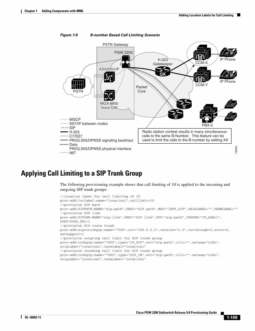
Chapter 1 Adding Components with MML Adding Location Labels for Call Limiting
Figure 1-9 B-number Based Call Limiting Scenario
Applying Call Limiting to a SIP Trunk GroupThe following provisioning example shows that call limiting of 10 is applied to the incoming and outgoing SIP trunk groups:
//location label for call limiting of 10 prov-add:loclabel:name="location1",calllimit=10 //provision SIP path prov-add:SIPPATH:NAME="sip-path",DESC="SIP path",MDO="IETF_SIP",ORIGLABEL="",TERMLABEL="" //provision SIP linkprov-add:SIPLNK:NAME="sip-link",DESC="SIP link",SVC="sip-path",IPADDR="IP_Addr1",PORT=5060,PRI=1 //provision SIP route trunk prov-add:siprttrnkgrp:name="7000",url="192.0.2.2",version="2.0",cutthrough=2,srvrr=2,extsupport=1 //provision outgoing call limit for SIP trunk group prov-add:trnkgrp:name="7000",type="IP_SIP",svc="sip-path",clli="",selseq="LIDL",origlabel="location1",termlabel="location1" //provision incoming call limit for SIP trunk group prov-add:trnkgrp:name="7000",type="SIP_IN",svc="sip-path",clli="",selseq="LIDL",origlabel="location1",termlabel="location1"
IP
IP
V
V
IP PhoneH.323Gatekeeper
PacketCore
PSTN Gateway
PSTN
IP Phone
PBX-2
PGW 2200
Radio station contest results in many simultaneouscalls to the same B-Number. This feature can beused to limit the calls to the B-number by setting XX
MGCPSS7/IP between nodesSIPH.323C7/SS7PRI/Q.SIG/DPNSS signaling backhaulDataPRI/Q.SIG/DPNSS physical interfaceIMT
AS5X00/UPAS5X00/UP
MGX 8800Voice GWMGX 8800Voice GW
GK
CCM-X
M
M
CCM-Y
V
V
1380
60
1-109Cisco PGW 2200 Softswitch Release 9.8 Provisioning Guide
OL-18092-11

Chapter 1 Adding Components with MML Adding Location Labels for Call Limiting
Applying Call Limiting to an H.323 Trunk GroupThe following provisioning example shows that call limiting is applied to an H.323 trunk group for both incoming and outgoing trunk groups (for example, call limit for the H.323 side is 20):
prov-add:loclabel:name="location2",calllimit=20//provision EISUP path to HSI, PGW are connected with H.323 network by HSI prov-add:EISUPPATH:NAME="eisup-hsi",DESC="to orchid",EXTNODE="sh-hsi",CUSTGRPID="1111" //provision call limit for H.323 trunk groupprov-add:trnkgrp:name="6000",CLLI="sh-daisy",svc="eisup-hsi",type="IP",selseq="ASC",qable="N",origlabel="location2",termlabel="location2"
Note Either the EISUP path or the HSI trunk group can be provisioned with location label.
Applying Call Limiting to the DPNSS Trunk GroupsThe following provisioning example shows that call limiting is applied to the DPNSS trunk groups (for example, call limit for DPNSS trunk group is 30) on both terminating and originating trunk groups:
prov-add:loclabel:name=”location3",calllimit=30//provision DPNSS pathprov-add:DPNSSPATH:NAME="dpnss-path2",DESC="dpnss va-3745-2",EXTNODE="va-3745-2",CUSTGRPID="1111",SIGSLOT=1,SIGPORT=1,ORIGLABEL="",TERMLABEL="" //provision call limit for DPNSS trunk groupprov-add:trnkgrp:name="5331",type="TDM_DPNSS",svc="dpnss-path1",clli="va-3745-2",selseq="ASC",qable="N",origlabel="location3",termlabel="location3"
Applying Call Limiting to an SS7 ISUP Trunk GroupThe following provisioning example shows that call limiting is applied to SS7 (for example, the call limit for the SS7 trunk group is 40) either incoming or outgoing, and make an announcement when the number of calls exceeds the call limit threshold:
//call limit is 10 prov-add:loclabel:name="location1",calllimit=10 //provision both incoming and outgoing call limit for SS7 trunk groupprov-add:trnkgrp:name="7000",type="TDM_ISUP",svc="ss7svc1",clli="7000',selseq="ASC",qable="N",origlabel="location1",termlabel="location1"
//The following is to provision incoming call limiting
//provision incoming call limit for SS7 trunk groupprov-add:trnkgrp:name="7000",type="TDM_ISUP",svc="ss7svc1",clli="7000',selseq="ASC",qable="N",origlabel="location1",termlabel=""
//The following is to provision outgoing call limiting
//provision outgoing call limit for SS7 trunk groupprov-add:trnkgrp:name="7000",type="TDM_ISUP",svc="ss7svc1",clli="7000',selseq="ASC",qable="N",origlabel="",termlabel="location1"
//The following is to play an announcement when calls are rejected due to exceeding threshold set by limiting
//announcement provisioning numan-add:announcement:annid=123,gwtype="AS5400",duration="60",repeat="2",interval="3",locationstring="xyz.aud"
1-110Cisco PGW 2200 Softswitch Release 9.8 Provisioning Guide
OL-18092-11

Chapter 1 Adding Components with MML Adding Location Labels for Call Limiting
//provision local announcementnuman-add:resulttable:custgrpId="1111",name="result60",resulttype="ANNOUNCEMENT", dw1="123",dw2="0",dw4="1",setname="set1" //call limit reject internal code is 171numan-add:cause:custgrpid="1111",causevalue="171",setname="set1"
Applying Call Limiting to Digit Strings in a Dial PlanThe following provisioning examples show that call limiting applied to A- and B-numbers by the dial plan and digits analysis:
1. This is the example that all incoming calls that B-numbers have prefix of 300XXX, calling limiting for 300XXXX is set to 100.
prov-add:loclabel:name="location2",calllimit=100// provision a result set numan-add:resultset:custgrpid=”1111“,name=“set200”//provision call limit location label in the result set numan-add:resulttable:resulttype="LOC_LABEL",dw1="location2",setname="set200",custgrpid="1111",name="resultloc200“ //provision route resulttablenuman-add:resulttable:custgrpid="1111",name="result200",resulttype="ROUTE",dw1="rtlist2",setname="set200" //provision Bdigtree for B-number 300XXXnuman-add:bdigtree:custgrpid="1111",callside="originating",digitstring=“300",setname="set200"
2. For example, if all incoming calls that A-numbers have prefix of 300XXX, calling limiting for 300XXXX is set to 100.
numan-add:resultset:custgrpid=”1111“,name=“set201” //provision call limit location label in the result set numan-add:resulttable:resulttype="LOC_LABEL",dw1="location2",setname="set201",custgrpid="1111",name="resultloc201" //provision Adigtree for A-number 300XXXnuman-add:adigtree:custgrpid="1111",callside="originating",digitstring=“300",setname="set201"
Applying Call Limiting to Multiple Trunk GroupsThe following provisioning example shows that one calling label can be applied to multiple trunks and trunk groups, which are either incoming or outgoing:
prov-add:loclabel:name="location3",calllimit=100//location label 3 can be used as SIP incoming trunk group 7000 prov-add:trnkgrp:name="7000",type="IP_SIP",svc="sip-path",clli="",selseq="LIDL",origlabel="location3" //location label 3 can be used as SIP outgoing trunk group 8000 prov-add:trnkgrp:name="8000",type="IP_SIP",svc="sip-path",clli="",selseq="LIDL",termlabel="location3" //location label 3 can be used as DPNSS trunk group 9000prov-add:trnkgrp:name="9000",type="TDM_DPNSS",svc="dpnss-path1",clli="va-3745-2",selseq="ASC",qable="N",origlabel="location3",termlabel="location3"
1-111Cisco PGW 2200 Softswitch Release 9.8 Provisioning Guide
OL-18092-11
Chapter 1 Adding Components with MML Adding Location Labels for Call Limiting
Applying Call Limiting to IP AddressesThe following provisioning example shows that the call limiting feature can be applied to source and destination IP addresses indirectly by the dial plans.
1. Call limiting to the other peer Cisco PGW 2200 Softswitch IP addresses.
Assuming a peer Cisco PGW 2200 Softswitch IP address is 192.0.2.1, call limiting for EISUP is 100, call limiting can be provisioned in EISUP for the sigPath or trunk group.
Option 1: Setting call limiting with an EISUP sigPath.
prov-add:loclabel:name="location5",calllimit=100//provision call limit in EISUP path prov-add:EISUPPATH:NAME="eisup-orkid",DESC="to orchid",EXTNODE="sh-orchid", CUSTGRPID="1111",ORIGLABEL="location5",TERMLABEL="location5" //provision EISUP IP link prov-add:IPLNK:NAME="elinkorchid1",DESC="Link to orchid",SVC="eisup-orchid",IPADDR="IP_Addr1",PORT=8001,PEERADDR="192.0.2.1",PEERPORT=8001,PRI=1,IPROUTE=""
Option 2: Set call limiting with an EISUP trunk group, for example, the trunk group is 6000.
prov-add:loclabel:name="location5",calllimit=100prov-add:EISUPPATH:NAME="eisup-orkid",DESC="to orchid",EXTNODE="sh-orchid",CUSTGRPID="1111"//provision EISUP IP link prov-add:IPLNK:NAME="elinkorchid1",DESC="Link to orchid",SVC="eisup-orchid",IPADDR="IP_Addr1",PORT=8001,PEERADDR="192.0.2.1",PEERPORT=8001,PRI=1,IPROUTE=""//provision call limit in EISUP trunk groupprov-add:trnkgrp:name="6000",type="IP",svc="eisup-daisy",clli="sh-daisy",selseq="ASC",origlabel="location5",termlabel="location5"
2. Call limiting for other SIP servers.
Assuming a SIP proxy IP address is 192.0.2.10, call limiting is set to 100, call limiting can be provisioned in the trunk group, for example, trunk group 7000.
prov-add:loclabel:name="location6",calllimit=100//provision SIP path prov-add:SIPPATH:NAME="sip-path",DESC="SIP path",MDO="IETF_SIP",ORIGLABEL="",TERMLABEL="" //provision SIP linkprov-add:SIPLNK:NAME="sip-link",DESC="SIP link",SVC="sip-path",IPADDR="IP_Addr1",PORT=5060,PRI=1 //provision SIP route trunk prov-add:siprttrnkgrp:name="7000",url="192.0.2.10",version="2.0",cutthrough=2,srvrr=2,extsupport=1 //provision call limit in SIP trunk groupprov-add:trnkgrp:name="7000",type="IP_SIP",svc="sip-path",clli="",selseq="LIDL",origlabel="location6",termlabel="location6"
Applying Call Limiting to an MGCP GatewayThe following example shows that call limiting is applied to an MGCP gateway with IP address of 192.0.2.4, the gateway has 4 trunk groups, which are controlled by ss7svc1, and the call limiting is set to 20:
prov-add:loclabel:name="location8",calllimit=20//provision MGCP path prov-add:MGCPPATH:NAME="mgcp530011",DESC="MGCP service to AS-5300-11",EXTNODE="va-5300-11" //provision IP linkprov-add:IPLNK:NAME="clink11-1",DESC="MGCPlink to sh-5300-11",SVC="mgcp530011",IPADDR="IP_Addr1",PORT=2427,PEERADDR="192.0.2.4",PEERPORT=2427,PRI=1,IPROUTE=""
1-112Cisco PGW 2200 Softswitch Release 9.8 Provisioning Guide
OL-18092-11
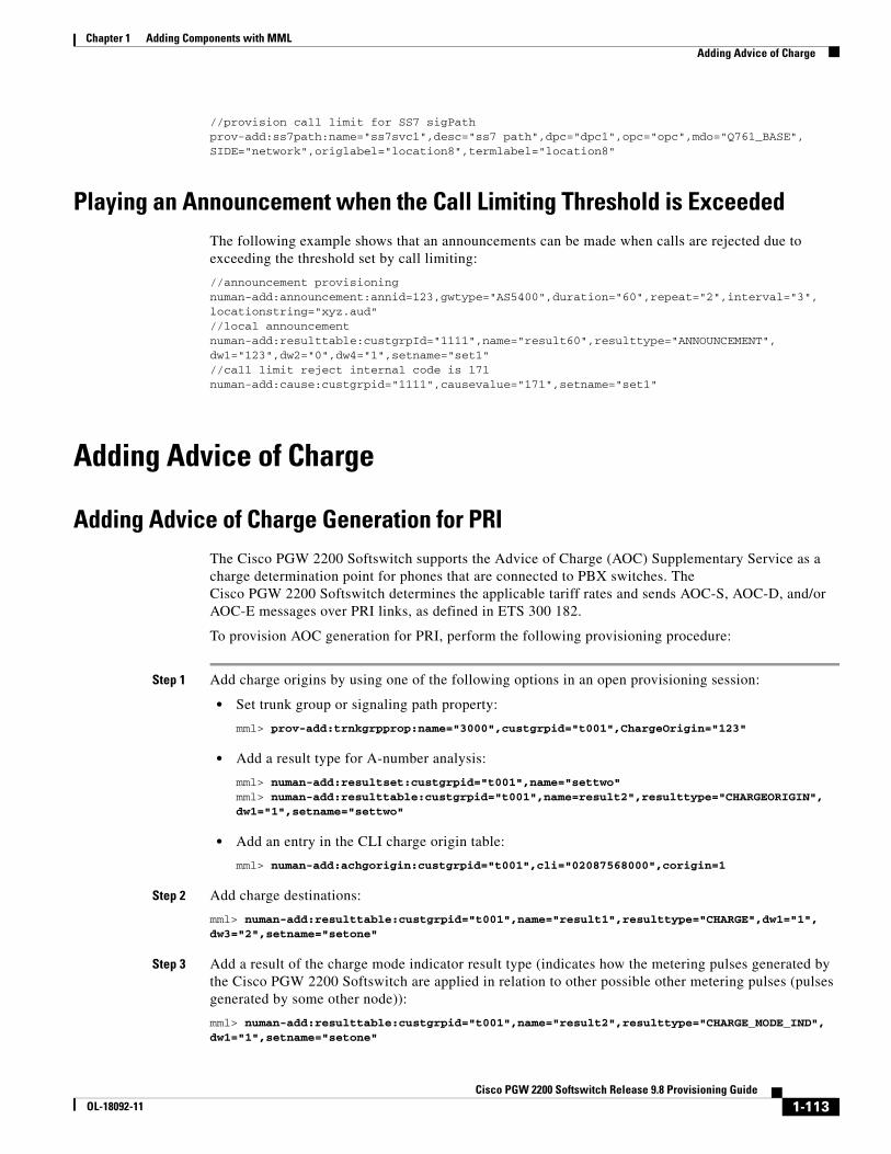
Chapter 1 Adding Components with MML Adding Advice of Charge
//provision call limit for SS7 sigPathprov-add:ss7path:name="ss7svc1",desc="ss7 path",dpc="dpc1",opc="opc",mdo="Q761_BASE",SIDE="network",origlabel="location8",termlabel="location8"
Playing an Announcement when the Call Limiting Threshold is ExceededThe following example shows that an announcements can be made when calls are rejected due to exceeding the threshold set by call limiting:
//announcement provisioning numan-add:announcement:annid=123,gwtype="AS5400",duration="60",repeat="2",interval="3",locationstring="xyz.aud" //local announcementnuman-add:resulttable:custgrpId="1111",name="result60",resulttype="ANNOUNCEMENT",dw1="123",dw2="0",dw4="1",setname="set1" //call limit reject internal code is 171numan-add:cause:custgrpid="1111",causevalue="171",setname="set1"
Adding Advice of Charge
Adding Advice of Charge Generation for PRIThe Cisco PGW 2200 Softswitch supports the Advice of Charge (AOC) Supplementary Service as a charge determination point for phones that are connected to PBX switches. The Cisco PGW 2200 Softswitch determines the applicable tariff rates and sends AOC-S, AOC-D, and/or AOC-E messages over PRI links, as defined in ETS 300 182.
To provision AOC generation for PRI, perform the following provisioning procedure:
Step 1 Add charge origins by using one of the following options in an open provisioning session:
• Set trunk group or signaling path property:
mml> prov-add:trnkgrpprop:name="3000",custgrpid="t001",ChargeOrigin="123"
• Add a result type for A-number analysis:
mml> numan-add:resultset:custgrpid="t001",name="settwo"mml> numan-add:resulttable:custgrpid="t001",name=result2",resulttype="CHARGEORIGIN", dw1="1",setname="settwo"
• Add an entry in the CLI charge origin table:
mml> numan-add:achgorigin:custgrpid="t001",cli="02087568000",corigin=1
Step 2 Add charge destinations:
mml> numan-add:resulttable:custgrpid="t001",name="result1",resulttype="CHARGE",dw1="1", dw3="2",setname="setone"
Step 3 Add a result of the charge mode indicator result type (indicates how the metering pulses generated by the Cisco PGW 2200 Softswitch are applied in relation to other possible other metering pulses (pulses generated by some other node)):
mml> numan-add:resulttable:custgrpid="t001",name="result2",resulttype="CHARGE_MODE_IND",dw1="1",setname="setone"
1-113Cisco PGW 2200 Softswitch Release 9.8 Provisioning Guide
OL-18092-11

Chapter 1 Adding Components with MML Adding Advice of Charge
Step 4 Add a result of the charge indicator result type (indicates if the Cisco PGW 2200 Softswitch should change the value of the charge indicator):
mml> numan-add:resulttable:custgrpid="t001",name="result3",resulttype="CHARGE_IND",dw1="1",setname="setone"
Step 5 (Optional) Add a holiday (for December 25, 2010:):
mml> prov-add:holiday:date="101225",hday="hol1"
Step 6 Add an entry in the PRI charge table:
mml> prov-add:pricharge:chorig=2,chdest=2,dow="HOL1",stariffdesc="1 1815 3 2100 2"
Step 7 Add an entry in the PRI tariff table:
mml> prov-add:pritariff:tariffid=2,schargeditem=1,sca=1,srecchrg=1,drecchrg=1,erecchrg=1, currency="USD",amount=1,amtmult=3,timelen=1,timescale=2,granularity=1,granularityscale=2, vol=1,scu=1,billingid=1
Step 8 Set the activation type, per call, for AOC supplementary services:
mml> prov-add:trnkgrpprop:name="3333",custgrpid="1111",AOCInvokeType="1"
Step 9 Set default tariff for AOC, 99, supplementary services:
mml> prov-add:trnkgrpprop:name="101",custgrpid="ABC234",AOCDefaultTariffId="99"
Step 10 Set default charging unit duration (indicates the interval after which the charging unit is updated to the subscriber by sending a facility message) for AOC-D supplementary services:
mml> prov-add:sigsvcprop:NAME="ABCNET1",AOCDMinPeriodicTimerDuration="5"
Step 11 Enable the AOC supplementary services:
mml> prov-add:trnkgrpprop:name="2000",aocenabled="1"
Step 12 If you don’t have other components to provision, end your provisioning session.
Adding Meter Pulse Messages SupportThe Cisco PGW 2200 Softswitch can handle meter pulse message pass through, modification, and generation. Billing information is derived from and provided to the billing mediator using Call Detail Records (CDRs)).
Before you provision this feature, configure parameters in the XECfgParm.dat file as follows:
engine.DisableMultipleCDRs = 1 # 0=enable, 1=disableengine.ChargingTariffType = 0 # 0=tariff-rate/scale-factor, 1=meter pulseengine.ChargingMode = 1 # 0=AddOnCharge, 2=ReplaceCharge, 3=FreeOfChargeengine.ShortDurationCallPeriod = 0 # 0=feature disabledengine.ActionOnChargeTableAccessFailure = 0 # 0=contiue call, 1=release call
Note For details on the previous parameters, see Appendix A, XECfgParm.dat File Parameters, in Cisco PGW 2200 Softswitch Release 9.8 Software Installation and Configuration Guide.
For the provisioning procedure on meter pulse messsages support, see the Combined Charge and Meter Pulse Messaging Provisioning section in Cisco PGW 2200 Softswitch Release 9.8 Dial Plan Guide.
1-114Cisco PGW 2200 Softswitch Release 9.8 Provisioning Guide
OL-18092-11

Chapter 1 Adding Components with MML Adding Intelligent Network Application Part
Adding Intelligent Network Application PartThe Cisco PGW 2200 Softswitch supports INAP calls.
To provision INAP, perform the following procedures:
Step 1 Add an SCP as the adjacent point code (APC) by using the following MML command in an open provisioning session:
mml> prov-add:APC:NAME="scp",DESC="SCP point code",NETADDR="0.111.2",NETIND=2
Step 2 Add an SS7 route to the SCP:
mml> prov-add:SS7ROUTE:NAME="ss7r-scp",DESC="SS7 Route towards SCP",OPC="opc-pgw", DPC="scp",LNKSET="lnkset-1",PRI=1
Step 3 Add an SS7 subsystem for the SCP:
mml> prov-add:SS7SUBSYS:NAME="scp-ss7subs",DESC="SS7 Subsystem for SCP",SVC="scp",PRI=1, MATEDAPC="",LOCALSSN=12,PROTO="SS7-ITU",STPSCPIND=4,TRANSPROTO="SCCP",OPC="opc-pgw", SUAKEY="",REMOTESSN=12
Step 4 Add a result of the IN_TRIGGER result type, and a result of the IN_SERVICE_KEY result type into the result set INservice1:
mml> numan-add:resultset:custgrpid="PSTN",name="INservice1"
mml> numan-add:resulttable:custgrpid="PSTN",name="INtrigger",resulttype="IN_TRIGGER",dw1="24",dw2="4",dw3="0",dw4="6",setname="INservice1" mml> numan-add:resulttable:custgrpid="PSTN",name="Servicekey1",resulttype="IN_SERVICE_KEY",dw1="1",setname="INservice1"
Note Dataword1 of the result type, IN_SERVICE_KEY, indicates the IN service key to be used when intelligent network (IN) triggering is initiated towards SCP. For more information on result types, see Cisco PGW 2200 Softswitch Release 9.8 Dial Plan Guide.
Step 5 Add a result set, INservice2:
mml> numan-add:resultset:custgrpid="PSTN",name="INservice2"
mml> numan-add:resulttable:custgrpid="PSTN",name="INtrigger",resulttype="IN_TRIGGER", dw1="24",dw2="4",dw3="0",dw4="6",setname="INservice2" mml> numan-add:resulttable:custgrpid="PSTN",name="Servicekey2",resulttype="IN_SERVICE_KEY",dw1="2",setname="INservice2"
Step 6 Add a result set, INservice3:
mml> numan-add:resultset:custgrpid="PSTN",name="INservice3"
mml> numan-add:resulttable:custgrpid="PSTN",name="INtrigger",resulttype="IN_TRIGGER", dw1="24",dw2="4",dw3="0",dw4="6",setname="INservice3" mml> numan-add:resulttable:custgrpid="PSTN",name="Servicekey3",resulttype="IN_SERVICE_KEY",dw1="3",setname="INservice3"
Step 7 Add entries in B digit tree for the previous three result sets:
mml> numan-add:bdigtree:custgrpid="PSTN",callside="originating",digitstring="1234561",setname="INservice1"
mml> numan-add:bdigtree:custgrpid="PSTN",callside="originating",digitstring="1234562",setname="INservice2"
1-115Cisco PGW 2200 Softswitch Release 9.8 Provisioning Guide
OL-18092-11

Chapter 1 Adding Components with MML Adding Support for MGCP 1.0 and Additional MGCP Packages
mml> numan-add:bdigtree:custgrpid="PSTN",callside="originating",digitstring="1234563",setname="INservice3"
Step 8 If you don’t have other components to provision, end your provisioning session.
Adding Support for MGCP 1.0 and Additional MGCP PackagesThe Cisco PGW 2200 Softswitch supports MGCP 1.0 (IETF RFC 2705 bis 5) and additional MGCP packages, including the Announcement package, ATM package, and Bulk Audit package.
Before you provision support for MGCP 1.0 and additional MGCP packages, configure the engine.FaultRecoveryAuditTimer parameter in the XECfgParm.dat file.
engine.FaultRecoveryAuditTimer = 15000 # milliseconds
Note The engine.FaultRecoveryAuditTimer parameter defines the interval between consecutive background audit procedures. The default value for this parameter is 15000. For details on the parameter, see Appendix A, XECfgParm.dat File Parameters, in Cisco PGW 2200 Softswitch Release 9.8 Software Installation and Configuration Guide.
To provision support for MGCP 1.0 and additional MGCP packages, perform the following procedure:
Step 1 Add an announcement in the ToneAndAnnouncement database by using the following MML command in an open provisioning session:
mml> numan-add:announcement:annid=123,gwtype="AS5400",duration=60,repeat=2,interval=3, locationstring="xyz.aud"
Step 2 Add a result of the ANNOUNCEMENT result type (announcement ID (dw1) set to 123):
mml> numan-add:resulttable:custgrpId="T002",name="result10",resulttype="ANNOUNCEMENT", dw1="123",dw2="0",dw4="1",setname="setname1"
Step 3 Add an entry in the B digit tree:
mml> numan-add:bdigtree:custgrpid="T002",digitstring="7034843355",callside="originating",setname="setname1"
Step 4 Add an ATM profile to change network Service Level Agreement:
mml> prov-add:atmprofiles:name="atmprof1",atmprofiles="ITU1;custom100"
Step 5 Add a result of the ATM_ORIG_PROFILE result type to deliver a profile list configured according to the Service Level Agreement requirements for the originating side, ATM_TERM_PROFILE for the terminating side:
mml> numan-add:resulttable:custgrpId="T002",name="result59", resulttype="ATM_ORIG_PROFILE",dw1="atmprof1",dw2="1",setname="setname1"
mml> numan-add:resulttable:custgrpId="T002",name="result60", resulttype="ATM_TERM_PROFILE",dw1="atmprof1",dw2="1",setname="setname1"
Step 6 Provision trunk group properties:
mml> prov-add:trnkgrp:name="1000",svc="ss7svc1",type="ATM"mml> prov-ed:trnkgrpprop:name="1000",playannouncement="0"
1-116Cisco PGW 2200 Softswitch Release 9.8 Provisioning Guide
OL-18092-11
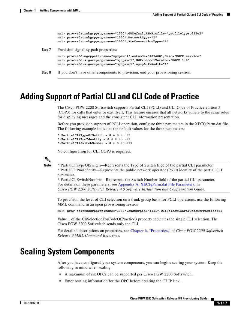
Chapter 1 Adding Components with MML Adding Support of Partial CLI and CLI Code of Practice
mml> prov-ed:trnkgrpprop:name="1000",GWDefaultATMProfile="profile1;profile2"mml> prov-ed:trnkgrpprop:name="1000",NetworkType="1"mml> prov-ed:trnkgrpprop:name="1000",AtmConnectionType="4"
Step 7 Provision signaling path properties:
mml> prov-add:mgcppath:name="mgcpsvc1",extnode="AS5400",desc="MGCP service"mml> prov-add:sigsvcprop:name="mgcpsvc1",GWProtocolVersion="MGCP 1.0"mml> prov-add:sigsvcprop:name="mgcpsvc1",mgcpBulkAudit="1"
Step 8 If you don’t have other components to provision, end your provisioning session.
Adding Support of Partial CLI and CLI Code of PracticeThe Cisco PGW 2200 Softswitch supports Partial CLI (PCLI) and CLI Code of Practice edition 3 (COP3) for calls that enter or exit itself. This feature ensures that all networks adhere to the same rules for displaying messages and the consistent CLI information presentation.
Before you provision support of PCLI operation, configure three parameters in the XECfgParm.dat file. The following example indicates the default values for the three parameters:
*.PartialCliTypeOfSwitch = 0 # 0 to 99*.PartialCliPnoIdentity = 0 # 0 to 999*.PartialCliSwitchNumber = 0 # 0 to 999
No configuration for CLI COP3 is required.
Note *.PartialCliTypeOfSwitch—Represents the Type of Switch filed of the partial CLI parameter. *.PartialCliPnoIdentity—Represents the public network operator (PNO) identity of the partial CLI parameter. *.PartialCliSwitchNumber—Represents the Switch Number field of the partial CLI parameter. For details on these parameters, see Appendix A, XECfgParm.dat File Parameters, in Cisco PGW 2200 Softswitch Release 9.8 Software Installation and Configuration Guide.
To provision the level of CLI selection on a trunk group basis for PCLI operations, use the following MML command in an open provisioning session:
mml> prov-ed:trnkgrpprop:name="3333",custgrpid="1111",CliSelectionForCodeOfPractice3=1
Value 1 of the CliSelectionForCodeOfPractice3 property indicates the single CLI selection. The Cisco PGW 2200 Softswitch sends only the CLI.
For detailed descriptions on properties, see Chapter 6, “Properties,” of Cisco PGW 2200 Softswitch Release 9 MML Command Reference.
Scaling System ComponentsAfter you have configured your system components, you can begins scaling your system. Keep the following in mind when scaling:
• A maximum of six OPCs can be supported per Cisco PGW 2200 Softswitch.
• Enter routing information for the OPC before creating the C7 IP link.
1-117Cisco PGW 2200 Softswitch Release 9.8 Provisioning Guide
OL-18092-11

Chapter 1 Adding Components with MML Scaling System Components
• For each OPC added, you must specify a different local port for each C7 IP link.
• Provision a maximum of 32 links per local port number. Specify another port number for each additional group of 32 links. As many as 192 links can be supported per Cisco PGW 2200 Softswitch.
• Planning for future network expansion by spreading the linksets evenly across the Control Channels is suggested. Failure to do so will require the linksets to be removed from service to add more links.
• As many as 256 NASs can be supported.
• When creating IP links to the NASs, increment the Cisco PGW 2200 Softswitch port number after 32 links have been added. Be sure to set the NAS RLM to match the Cisco PGW 2200 Softswitch RLM port value.
Dynamically Configuring the Input/Output Channel ControllerWhen dynamically configuring the IOCC, evenly distribute number of channels associated with one channel controller. For different signaling service, there are different rules when associating channels with channel controllers. The number of links associated with a channel controller is configurable on a protocol family basis through parameters contained in XECfgParm.dat. If the number of links exceeds the limit defined in XECfgParm.dat, a new instance of channel controller is created.
The naming convention for creating a new channel controller is the first five characters of the protocol family, plus a dash (-), and <num>, where num is number of channel controllers per protocol family created so far.
Scaling Criteria and LimitsTable 1-8 lists the scaling criteria and limits by protocol family.
1-118Cisco PGW 2200 Softswitch Release 9.8 Provisioning Guide
OL-18092-11

Chapter 1 Adding Components with MML Scaling System Components
Table 1-8 Scaling Links per Protocol Family
Signaling Type
Protocol Family Criteria for a Unique IOCC Criteria for a Valid Link (Channel)
Parameter in XECfgParm.dat (Default maximum number of links)
NAS PRIIP Port number.
Number of links.
When a channel controller is created, the RLM port number is created as the property port for this channel with the value of the actual port number (minus 1) in properties.dat. The format is:
<IOCC MML Name>.port = <port number> - 1
Local port and peer port must be the same.
The port number must always be an odd number.
The number of links on the same port cannot exceed the maximum number of links specified in XECfgParm.dat.
Links associated with the same signaling service must use the same port number. (that is, redundant links).
Redundant links do not count when validating the maximum number of links per IOCC.
MaxNumLinks
(32)
IPFAS PRIL3 Number of links.
Links associated with the same port number cannot be split over different channel controllers.
The number of links on the same port cannot exceed the maximum number of links specified in XECfgParm.dat.
Links associated with the same signaling service must use the same port number. (that is, redundant links).
Redundant links do not count when validating the maximum number of links per IOCC.
MaxNumPRIL3Links
(168)
MGCP MGCP Number of links.
Links associated with the same port number cannot split over different channel controllers.
The number of links on the same port cannot exceed the maximum number of links specified in XECfgParm.dat.
Links associated with the same signaling service must use the same port number. (that is, redundant links).
Redundant links do not count when validating the maximum number of links per IOCC.
MaxNumMGCPLinks
(1000)
SGCP SGCP Number of links. — MaxNumLinks (32)
EISUP EISUP Number of links. — MaxNumLinks (32)
FAS ISDNPRI
DPNSS
Number of links. — MaxNumLinks (32)
TCAPOverIP
TCAPOverIP
Number of links. — MaxNumLinks (32)
1-119Cisco PGW 2200 Softswitch Release 9.8 Provisioning Guide
OL-18092-11

Chapter 1 Adding Components with MML Scaling System Components
Table 1-9 lists the scaling limits for SS7 components.
SS7 SS7-ANSI
SS7-UK
SS7-ITU
SS7-China
SS7-Japan
Protocol Family
Switch Type
OPC
Number of links.
Protocol Family Switch Type MaxNumLinks (32)
— — — SS7-ANSI 0 —
— — — SS7-China 0, 5 —
— — — SS7-ITU 0, 5 —
— — — SS7-Japan 0, 10 —
— — — SS7-UK 0, 5 —
Table 1-8 Scaling Links per Protocol Family (continued)
Signaling Type
Protocol Family Criteria for a Unique IOCC Criteria for a Valid Link (Channel)
Parameter in XECfgParm.dat (Default maximum number of links)
Table 1-9 Maximum Scaling Limits for the SS7 Components
Component Scaling Limit
SS7 IOCC Instances 6
Linksets per SS7 IOCC 16
Links per SS7 IOCC 32
DPCs per SS7 IOCC 256
True OPCs per SS7 IOCC 1
Routes per SS7 IOCC 512
Protocol families per SS7 IOCC 1
Switch types per SS7 IOCC 1
Links per Cisco PGW 2200 Softswitch* 192
Linksets per Cisco PGW 2200 Softswitch* 96
True OPCs per Cisco PGW 2200 Softswitch* 6
DPCs per Cisco PGW 2200 Softswitch* 600
Routes per Cisco PGW 2200 Softswitch* 1200
Capability point codes (8 per IOCC) 48
M3UA true OPCs per Cisco PGW 2200 Softswitch 64
M3UA routes per OPC/DPC pair per Cisco PGW 2200 Softswitch 2
M3UA SGPs per Cisco PGW 2200 Softswitch 96
M3UA signaling services per Cisco PGW 2200 Softswitch 1536
* Indicates the component must be spread evenly across the maximum number of IOCC instances.
1-120Cisco PGW 2200 Softswitch Release 9.8 Provisioning Guide
OL-18092-11
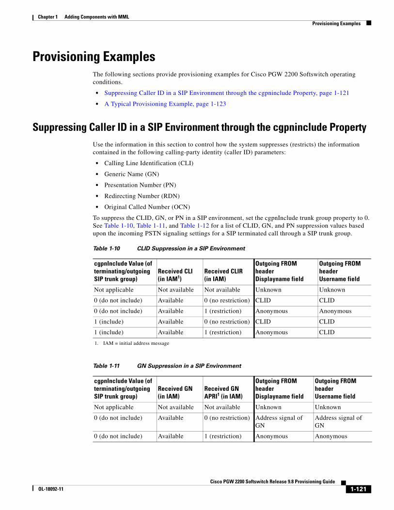
Chapter 1 Adding Components with MML Provisioning Examples
Provisioning ExamplesThe following sections provide provisioning examples for Cisco PGW 2200 Softswitch operating conditions.
• Suppressing Caller ID in a SIP Environment through the cgpninclude Property, page 1-121
• A Typical Provisioning Example, page 1-123
Suppressing Caller ID in a SIP Environment through the cgpninclude PropertyUse the information in this section to control how the system suppresses (restricts) the information contained in the following calling-party identity (caller ID) parameters:
• Calling Line Identification (CLI)
• Generic Name (GN)
• Presentation Number (PN)
• Redirecting Number (RDN)
• Original Called Number (OCN)
To suppress the CLID, GN, or PN in a SIP environment, set the cgpnInclude trunk group property to 0. See Table 1-10, Table 1-11, and Table 1-12 for a list of CLID, GN, and PN suppression values based upon the incoming PSTN signaling settings for a SIP terminated call through a SIP trunk group.
Table 1-10 CLID Suppression in a SIP Environment
cgpnInclude Value (of terminating/outgoing SIP trunk group)
Received CLI(in IAM1)
1. IAM = initial address message
Received CLIR(in IAM)
Outgoing FROM header Displayname field
Outgoing FROM header Username field
Not applicable Not available Not available Unknown Unknown
0 (do not include) Available 0 (no restriction) CLID CLID
0 (do not include) Available 1 (restriction) Anonymous Anonymous
1 (include) Available 0 (no restriction) CLID CLID
1 (include) Available 1 (restriction) Anonymous CLID
Table 1-11 GN Suppression in a SIP Environment
cgpnInclude Value (of terminating/outgoing SIP trunk group)
Received GN(in IAM)
Received GN APRI1 (in IAM)
Outgoing FROM header Displayname field
Outgoing FROM header Username field
Not applicable Not available Not available Unknown Unknown
0 (do not include) Available 0 (no restriction) Address signal of GN
Address signal of GN
0 (do not include) Available 1 (restriction) Anonymous Anonymous
1-121Cisco PGW 2200 Softswitch Release 9.8 Provisioning Guide
OL-18092-11
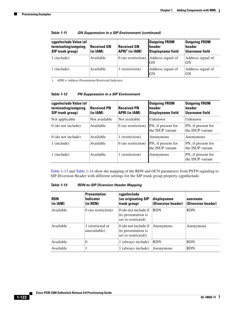
Chapter 1 Adding Components with MML Provisioning Examples
Table 1-13 and Table 1-14 show the mapping of the RDN and OCN parameters from PSTN signaling to SIP Diversion Header with different settings for the SIP trunk group property cgpnInclude.
1 (include) Available 0 (no restriction) Address signal of GN
Address signal of GN
1 (include) Available 1 (restriction) Address signal of GN
Address signal of GN
1. APRI = Address Presentation Restricted Indicator
Table 1-12 PN Suppression in a SIP Environment
cgpnInclude Value (of terminating/outgoing SIP trunk group)
Received PN(in IAM)
Received PN APRI (in IAM)
Outgoing FROM header Displayname field
Outgoing FROM header Username field
Not applicable Not available Not available Unknown Unknown
0 (do not include) Available 0 (no restriction) PN, if present for the ISUP variant
PN, if present for the ISUP variant
0 (do not include) Available 1 (restriction) Anonymous Anonymous
1 (include) Available 0 (no restriction) PN, if present for the ISUP variant
PN, if present for the ISUP variant
1 (include) Available 1 (restriction) Anonymous PN, if present for the ISUP variant
Table 1-11 GN Suppression in a SIP Environment (continued)
cgpnInclude Value (of terminating/outgoing SIP trunk group)
Received GN(in IAM)
Received GN APRI1 (in IAM)
Outgoing FROM header Displayname field
Outgoing FROM header Username field
Table 1-13 RDN-to-SIP Diversion Header Mapping
RDN(in IAM)
Presentation Indicator(in RDN)
cgpnInclude(on originating SIP trunk group)
displayname(Diversion header)
username(Diversion header)
Available 0 (no restriction) 0 (do not include if its presentation is set to restricted)
RDN RDN
Available 1 (restricted or unavailable)
0 (do not include if its presentation is set to restricted))
Anonymous Anonymous
Available 0 1 (always include) RDN RDN
Available 1 1 (always include) Anonymous RDN
1-122Cisco PGW 2200 Softswitch Release 9.8 Provisioning Guide
OL-18092-11

Chapter 1 Adding Components with MML Provisioning Examples
A Typical Provisioning ExampleHere is a typical provisioning example for your reference.
prov-sta::srcver="new",dstver="2lnks11"prov-add:opc:name="opc1",netaddr="1.2.1",netind=2,desc="OPC1",type="trueopc"prov-add:opc:name="opc1a",netaddr="1.2.2",netind=2,desc="OPC1",type="capopc", trueopc="opc1"prov-add:dpc:name="dpc1",netaddr="2.2.2",netind=2,desc="DPC1"prov-add:dpc:name="dpc2",netaddr="1.1.2",netind=2,desc="DPC2"prov-add:dpc:name="apc1",netaddr="3.3.3",netind=2,desc="apc1"prov-add:dpc:name="apc2",netaddr="3.3.2",netind=2,desc="apc2"prov-add:ss7path:name="c7s-1",desc="C7 Service to INET",mdo="ANSISS7_STANDARD", dpc="dpc1",custgrpid="1122",side="network",opc="opc1"prov-add:ss7path:name="c7s-2",desc="C7 Service to SIM",mdo="ANSISS7_STANDARD", dpc="dpc2",custgrpid="1122",side="network",opc="opc1"prov-add:lnkset:name="ls-1",desc="Linkset 1",apc="dpc1",type="IP",proto="SS7-ANSI"prov-add:lnkset:name="ls-2",desc="Linkset 2",apc="dpc2",type="IP",proto="SS7-ANSI"prov-add:EXTNODE:NAME="va-2600-stim1",DESC="stim1-2600 SLT",TYPE="SLT"prov-add:SESSIONSET:NAME="c7-2600-1",EXTNODE="va-2600-stim1",IPADDR1="IP_Addr1", PEERADDR1="209.165.200.250",PORT=7000,PEERPORT=7000,NEXTHOP1="0.0.0.0", NETMASK1="255.255.255.224",TYPE="BSMV0"prov-add:EXTNODE:NAME="va-2600-stim2",DESC="stim1-2600 SLT",TYPE="SLT"prov-add:SESSIONSET:NAME="c7-2600-2",EXTNODE="va-2600-stim2",IPADDR1="IP_Addr1", PEERADDR1="209.165.200.251",PORT=7000,PEERPORT=7000,NEXTHOP1="0.0.0.0", NETMASK1="255.255.255.224",TYPE="BSMV0"prov-add:ss7route:name="r1",opc="opc1",dpc="dpc1",lnkset="ls-1",pri=1,desc="SS7 Route"prov-add:ss7route:name="r2",opc="opc1",dpc="dpc2",lnkset="ls-2",pri=1,desc="SS7 Route"prov-add:c7iplnk:name="ip-ch1",pri=1,slc=0,lnkset="ls-1",desc="INET SS7",timeslot=0, sessionset="c7-2600-1"prov-add:c7iplnk:name="ip-ch2",pri=1,slc=1,lnkset="ls-1",desc="INET SS7",timeslot=1, sessionset="c7-2600-1"prov-add:c7iplnk:name="ip-ch3",pri=1,slc=3,lnkset="ls-2",desc="SIM SS7",timeslot=0, sessionset="c7-2600-2"prov-add:c7iplnk:name="ip-ch4",pri=1,slc=4,lnkset="ls-2",desc="SIM SS7",timeslot=1, sessionset="c7-2600-2"prov-add:trnkgrp:name="1",svc="c7s-1",type="TDM_ISUP",selseq="MIDL",clli="trk-1"prov-add:trnkgrp:name="2",svc="c7s-2",type="TDM_ISUP",selseq="MIDL",clli="trk-2"prov-add:extnode:name="mgcp1",type="CAT8510",desc="SIM"prov-add:mgcppath:name="mgcpsvc1",extnode="mgcp1",desc="MGCP to SIM"prov-add:iplnk:name="mgcplk1",if="enif2",ipaddr="IP_Addr2",port=2427,pri=1, peeraddr="209.165.201.21",peerport=2427,svc="mgcpsvc1",desc="IP Link for MGCP"
Table 1-14 OCN-to-SIP Diversion Header Mapping
OCN(in IAM)
Presentation Indicator(in OCN)
cgpnInclude(on originating SIP trunk group)
displayname(Diversion header)
username(Diversion header)
Available 0 (no restriction) 0 (do not include if its presentation is set to restricted)
OCN OCN
Available 1 (restricted or unavailable)
0 (do not include if its presentation is set to restricted)
Anonymous Anonymous
Available 0 1 (always include) OCN OCN
Available 1 1 (always include) Anonymous OCN
1-123Cisco PGW 2200 Softswitch Release 9.8 Provisioning Guide
OL-18092-11
Chapter 1 Adding Components with MML Display Name and Connected Number Interworking
prov-add:switchtrnk:name="01",trnkgrpnum="1",span="ffff",cic=1,cu="mgcp1", endpoint="s1/ds1-1/1@inet",spansize=24prov-add:switchtrnk:name="02",trnkgrpnum="2",span="ffff",cic=1,cu="mgcp1", endpoint="s1/ds1-2/1@sim",spansize=24prov-add:rttrnkgrp:name="1",type=1,reattempts=3,queuing=0,cutthrough=1prov-add:rttrnk:name="rt1",trnkgrpnum=1prov-add:rtlist:name="rtlist1",rtname="rt1"prov-add:rttrnkgrp:name="2",type=1,reattempts=3,queuing=0,cutthrough=1prov-add:rttrnk:name="rt2",trnkgrpnum=2prov-add:rtlist:name="rtlist2",rtname="rt2"prov-dplyprov-stp
Display Name and Connected Number InterworkingThe Display Name and Connected Number Interworking feature introduces a comprehensive structure for handling the parameters associated with the following features for calls between ISUP and SIP endpoints:
• Calling Line Identification Presentation (CLIP)
• Connected Line Identification Presentation (COLP)
• Calling Line Identification Restriction (CLIR)
• Connected Line Identification Restriction (COLR)
To provision display name and connected number interworking, perform the following steps:
Step 1 Start a provisioning session by using the following MML command:
mml> prov-sta::srcver="active",dstver="acgpn-map"
Step 2 Add a SIP Profile with the value of the mapclitosipheader property set to 5:
mml> prov-add:profile:name="profile1",type="SIPPROFILE",mapclitosipheader="5"
Note The value 5 of the mapclitosipheader property enables the Cisco PGW 2200 Softswitch to map the P-Asserted-Identity (PAID) and From headers of Invite message from ACgPN of IAM.
Step 3 Add a Service to the Dial Plan:
mml> numan-add:service:custgrpid="1000",name="ocntrans"
Step 4 Add an entry in the Full Number Translation table:
mml> numan-add:fullnumbertrans:svcname="ocntrans",digstring="8011",translatednum="778011",numtype="5"
Step 5 Add a result of the NUM_TRANS result type:
mml> numan-add:resultset:custgrpid="1000",name="set10"mml> numan-add:resulttable:custgrpid="1000",name="trans",resulttype="NUM_TRANS", dw1="ocntrans",dw2="5",dw3="4",setname="set10"
Step 6 Add an entry to the B digit tree:
mml> numan-add:bdigtree:custgrpid="1000",digitstring="10",callside="originating",setname="set10"
1-124Cisco PGW 2200 Softswitch Release 9.8 Provisioning Guide
OL-18092-11

Chapter 1 Adding Components with MML Domain Based Routing
Step 7 Add an entry in the Prefix Convert table:
mml> numan-add:prefixconvert:cdpnprefix="8012",cgpnprefix="8001",acgpnprefix="8002",previousprefix="8012",previousnoa="4",newprefix="648012",newnoa="4",newaddconprefix="74",newaddconnoa="4"
Step 8 Add a result of the PREFIX_CONVERT result type:
mml> numan-add:resultset:custgrpid="1000",name="set01"mml> numan-add:resulttable:custgrpid="1000",setname="set01",name="prefixconvert",resulttype="PREFIX_CONVERT"
Step 9 Add an entry in the B digit tree:
mml> numan-add:bdigtree:custgrpid="1000",callside="originating",setname="set01",digitstring="10"
Step 10 Add an entry in the A digit tree:
mml> numan-add:adigtree:custgrpid="1000",callside="originating",setname="set01",digitstring="80"
Step 11 End the provisioning session:
mml> prov-dply
Domain Based RoutingYou can find the provisioning procedure in the “Provisioning Domain Based Routing” section of Chapter 4, Provisioning Dial Plans with MML, in Cisco PGW 2200 Softswitch Release 9.8 Dial Plan Guide.
Enhanced Clear Channel Codec SupportThe clear channel codec guarantees bit integrity of a digital signal 0 (DS-0) transferred through a gateway. It supports the transporting of nonvoice circuit data sessions through a VoIP network. It enables the VoIP networks to transport data calls.
The Enhanced Clear Channel Codec Support feature completes clear channel codec support to SIP-to-TDM data calls. Based on incoming SIP messages and user configurations, the Cisco PGW 2200 Softswitch sends certain clear channel codecs to gateways and sets the transmission medium requirement (TMR) value for data calls properly. With this feature, users can make TDM data calls through the SIP network. In addition, users can customize clear channel codecs that media gateways use for data calls.
Before you provision this feature, configure the GWClearChannelAlgorithm parameter in the XECfgParm.dat file.
*.GWClearChannelAlgorithm = X-CCD;CLEARMODE;CCD;G.nX64;G.Clear # clear channel algorithm
Note Any changes of the XECfgParm.dat file require a restart of the Cisco PGW 2200 Softswitch software.
1-125Cisco PGW 2200 Softswitch Release 9.8 Provisioning Guide
OL-18092-11
Chapter 1 Adding Components with MML Enhanced Generic Number Handling
Note For details on the GWClearChannelAlgorithm parameter, see Appendix A, XECfgParm.dat File Parameters, in Cisco PGW 2200 Softswitch Release 9.8 Software Installation and Configuration Guide.
To provision enhanced clear channel codec support, you can use either of the following two procedures:
• Clear Channel Codec Check in the SDP of the First Incoming SIP INVITE Message, page 1-126
• Request Line Check in the First Incoming SIP INVITE Message, page 1-126
Clear Channel Codec Check in the SDP of the First Incoming SIP INVITE Message
Step 1 Add a SIP Profile in an open provisioning session by using the following MML command:
mml> prov-add:profile:name="sipprf",type="sipprofile",trustlevel="1"
Step 2 Enable the Clear Channel Codec check in the SDP:
mml> prov-ed:profile:name="sipprf",checkclearchannelcodecinsdp="1"
Step 3 End the provisioning session:
mml> prov-dply
Request Line Check in the First Incoming SIP INVITE Message
Step 1 Add a SIP Profile in an open provisioning session by using the following MML command:
mml> prov-add:profile:name="sipprf",type="sipprofile",trustlevel="1"
Step 2 Enable the Request Line check in the first incoming SIP INVITE message:
mml> prov-ed:profile:name="sipprf",checksiptgrpparam="1"
Step 3 Match the tgrp and the trunk-context parameter values:
mml> prov-ed:profile:name="sipprf",siptgrplabel="ccdata"mml> prov-ed:profile:name="sipprf",siptrunkcontext="abcd.com"
Step 4 End the provisioning session:
mml> prov-dply
Enhanced Generic Number HandlingThe Enhanced Generic Number Handling feature enables the Cisco PGW 2200 Softswitch to pass the Generic Number parameter present in a UK ISUP IAM message into the user field of the P-Asserted-ID header in a SIP INVITE message when the Number Qualifier field in the Generic Number is set to “intra-nw-use” (254 in the signaling). This feature introduces a new property called GenNumInclude. The GenNumInclude property enables or disables the feature as follows:
• When set to 1, the system maps the Generic Number in an IAM to the user field of the P-ASSERTED-ID Header in a SIP INVITE.
1-126Cisco PGW 2200 Softswitch Release 9.8 Provisioning Guide
OL-18092-11

Chapter 1 Adding Components with MML Enhanced Video Support
• When set to 0, the system does not map the Generic Number to the user field of the P-ASSERTED-ID Header in a SIP INVITE.
Note This feature is restricted to deployments in which the ISUP side is provisioned for the United Kingdom variant (ISUPV3_UK).
The Cisco PGW 2200 Softswitch performs this message conversion when it determines that it must set up a call between an ISUP network on the originating side and a SIP network on the destination side.
The following sample MML command sequence provisions the Enhanced Generic Number Handling feature. When provisioned, the Cisco PGW 2200 Softswitch passes a Generic Number received in an IAM to the username of a P-Asserted-ID in a SIP INVITE.
prov-ed:profile:name="sip-prof1",mapclitosipheader="3"prov-ed:profile:name="sip-prof1",CliSelectionForCodeOfPractice3 ="2"prov-ed:profile:name="sip-prof1",GenNumInclude="1".prov-add:profile:NAME="sippro1",type="grprofile",cgpninclude="0" prov-ed:profile:name="sip-prof1",grprofile="sippro"
Enhanced Video SupportThe Enhanced Video Support feature expands video capabilities on the Cisco PGW 2200 Softswitch.
Before the introduction of this feature, the Cisco PGW 2200 Softswitch handled Session Initiation Protocol (SIP) video calls in a basic way. You couldn’t hold or transfer SIP video calls. You did not have control of media streams for SIP video calls.
With this feature, you have more control of the call setup process for SIP video calls compared to the basic SIP calls.
To provision enhanced video support, perform the following steps:
Step 1 Add the Dial Plan 1111 after starting a provisioning session by using the following MML commands:
mml> prov-stpmml> prov-sta::srcver="active",dstver="PGW98videosupport",confirmmml> numan-add:dialplan:custgrpid="1111",overdec="yes"
Step 2 Add the data border element (DBE):
mml> prov-add:extnode:name="asr-1000",desc="asr1000",type="ASR1000",isdnsigtype="N/A",group=0mml> prov-add:H248PATH:name="h248-udp-asr1000",desc="service to asr1000",extnode="asr-1000"mml> prov-add:iplnk:name="h248-asr1000",desc="udp to asr1000",svc="h248-udp-asr1000",ipaddr="IP_Addr1",port=2944,peeraddr="33.33.36.1",peerport=2944,pri=1mml> prov-add:sigsvcprop:name="h248-udp-asr1000",GWProtocolVersion="H248 V2"
Step 3 Add a gateway pool profile with GatewayVideoSupport set to 1, a gateway pool that uses this profile, and an IP gateway into this gateway pool:
mml> prov-add:PROFILE:NAME="dbe-profile",TYPE="gwpoolprofile",gatewayselectionmethod="1",GatewayVideoSupport="1"mml> prov-add:GWPOOL:NAME="104",DESC="gsr",PROFILE="dbe-profile"mml> prov-add:IPGW:poolid="104",gw="asr-1000"
1-127Cisco PGW 2200 Softswitch Release 9.8 Provisioning Guide
OL-18092-11

Chapter 1 Adding Components with MML Enhanced Video Support
Step 4 Add the ingress SIP trunk group:
mml> prov-add:sippath:name="sip-path",mdo="IETF_SIP"mml> prov-add:siplnk:name="sip-lnk",ipaddr="IP_Addr1",svc="sip-path",port=5060,pri=1mml> prov-add:trnkgrp:name="888",clli="NULL",svc="sip-path",type="SIP_IN",selseq="LIDL",qable="N"
Step 5 Add the SIP profile for the ingress SIP trunk group and associate the profile with the trunk group:
mml> prov-add:profile:type="SIPPROFILE",name="incoming",custgrpid="1111",gatewaypool="104",insessiontimer="90",mgcdomain="10.0.49.117"
mml> prov-add:trnkgrpprof:name="888",profile="incoming"
Step 6 Provision the SIP profile for the ingress SIP trunk group:
mml> prov-ed:profile:name="incoming",videoallowed="1",unsolicitednotifymethod="1",anchormedia="3",anchorpolicy="1"
Note In the preceding MML command, you set the AnchorMedia property to 3 (always anchor media on the IP trunk group), and the AnchorPolicy property to 1 (enables the use of the gateway pool on an IP trunk group).
Step 7 Add a Level 2 (trunk group) codec list with the GWDefaultAudioCodecString and the GWDefaultVideoCodecString properties for ingress SIP trunk group:
mml> prov-ed:profile:name="incoming",gwdefaultaudiocodecstring="G.711u;G.711a"mml> prov-ed:profile:name="incoming",gwdefaultvideocodecstring="H264;H263;H261"
Step 8 Add a dummy codec list with the DummyAudioCodecString and the DummyVideoCodecString properties for ingress SIP trunk group.
mml> prov-ed:profile:name="incoming",dummyaudiocodecstring="G.711u;G.711a"mml> prov-ed:profile:name="incoming",dummyvideocodecstring="H264;H263;H261"
Note The Cisco PGW 2200 Softswitch uses the dummy video codecs in an H.248 add request when neither a remote SDP nor a local codec is provisioned.
Step 9 Add the egress SIP trunk group:
mml> prov-add:trnkgrp:name="5134",clli="NULL",svc="sip-path",type="IP_SIP",selseq="NULL",qable="N"
Step 10 Add the SIP profile for the egress SIP trunk group and associate the profile with the trunk group:
mml> prov-add:profile:type="SIPPROFILE",name="out5134",custgrpid="1111",anchormedia="3", gatewaypool="104",insessiontimer="90",mgcdomain="10.0.49.146" mml> prov-add:trnkgrpprof:name="5134",profile="out5134"
Step 11 Provision the SIP profile for the egress SIP trunk group:
mml> prov-ed:profile:name="out5134",videoallowed="1",unsolicitednotifymethod="1"mml> prov-ed:profile:name="out5134",gwdefaultaudiocodecstring="G.711u;G.711a"mml> prov-ed:profile:name="out5134",gwdefaultvideocodecstring="H264;H263;H261"mml> prov-ed:profile:name="out5134",dummyaudiocodecstring="G.711u;G.711a"mml> prov-ed:profile:name="out5134",dummyvideocodecstring="H264;H263;H261"
Step 12 Add the route and the route list:
mml> prov-add:siprttrnkgrp:name="5134",url="10.0.50.134",version="2.0",cutthrough=3, srvrr=0,extsupport=1,sipproxyport=5060mml> prov-add:rttrnk:name="rt51348",trnkgrpnum=5134,weightedtg="OFF"mml> prov-add:rtlist:name="rtlist51348",rtname="rt51348",distrib="OFF"
1-128Cisco PGW 2200 Softswitch Release 9.8 Provisioning Guide
OL-18092-11

Chapter 1 Adding Components with MML Generic Call Tagging
Step 13 Add the result set and the results:
mml> numan-add:resultset:custgrpid="1111",name="rs51348"mml> numan-add:resulttable:custgrpid="1111",name="bmodccm5",resulttype="BMODDIG",dw1="1", dw2="3",setname="rs51348"mml> numan-add:resulttable:custgrpid="1111",name="rtb51348",setname="rs51348", resulttype="ROUTE",dw1="rtlist51348"
Step 14 Add Level 3 (dial plan) codec lists:
mml> prov-add:codecstring:name="videocodec1",codecstring="H263;H261"mml> prov-add:codecstring:name="audiocodec1",codecstring="G.711u;G.711a"mml> numan-add:resultset:custgrpid="1111",name="rs513381"mml> numan-add:resulttable:custgrpid="1111",name="rescodecres133", resulttype="VIDEO_ALLOWED",dw1="1",setname="rs513381"
mml> numan-add:resulttable:custgrpid="1111",name="rstaudiocodec5133",resulttype="CODEC",dw1="audiocodec1",dw2="0",dw3="0",setname="rs513381"mml> numan-add:resulttable:custgrpid="1111",name="rstvideocodec5133",resulttype="CODEC",dw1="videocodec1",dw2="0",dw3="1",setname="rs513381"
Step 15 Add entries in B digit tree:
mml> numan-add:bdigtree:custgrpid="1111",callside="originating",digitstring="64666", setname="rs51348"mml> numan-add:bdigtree:custgrpid="1111",callside="originating",digitstring="64670", setname="rs513381"
Step 16 End the provisioning session:
mml> prov-dply
Generic Call TaggingYou can find the provisioning procedure in the “Provisioning Generic Call Tagging” section of Chapter 4, Provisioning Dial Plans with MML, in Cisco PGW 2200 Softswitch Release 9.8 Dial Plan Guide.
H.248 Protocol–Phase 2H.248 Protocol–Phase 2 enables the Cisco PGW 2200 Softswitch to perform media anchoring on ingress or egress border gateways for IP traffic. This feature includes a simple service policy decision module (SPDM), which determines whether a signaling border element (SBE) should perform media anchoring and, if so, identifies which border gateway will perform the media anchoring based on service requirements. The border gateway control interface conforms to the ITU-SG16/IETF specification of the H.248 protocol and an additional optional package.
Note The Cisco PGW 2200 Softswitch can serve as an SBE on Release 9.8(1).
By supporting media anchoring, a gateway can
• Play announcements
1-129Cisco PGW 2200 Softswitch Release 9.8 Provisioning Guide
OL-18092-11
Chapter 1 Adding Components with MML H.248 Protocol–Phase 2
• Select codecs
• Detect DTMF
• Support tones
For detailed descriptions on properties, see Chapter 6, “Properties,” of Cisco PGW 2200 Softswitch Release 9 MML Command Reference.
For detailed descriptions on the result types, see Chapter 1, “Dial Plan and Routing,” of Cisco PGW 2200 Softswitch Release 9.8 Dial Plan Guide.
To provision H.248 Protocol–Phase 2, perform the following steps:
Step 1 Add a gateway pool for a data border element (DBE) in an open provisioning session by using the following MML command:
mml> prov-add:PROFILE:NAME="DBE-Profile1",TYPE="GWPOOLPROFILE",VALIDATION="ON", CAT="profile",GatewayAnnSupport="0",GatewayCodecSupport ="0",GatewayDTMFSupport="1", GatewayToneSupport="0",GatewaySelectionMethod="1"
mml> prov-add:GWPOOL:NAME="101", DESC="DBE GW POOL TO CUSTOMER 1", PROFILE="DBE-Profile1"
Step 2 Add a gateway pool for a Cisco Voice Switch Service Module (VXSM) gateway:
mml> prov-add:PROFILE:NAME="VXSM-Profile1",TYPE="GWPOOLPROFILE",VALIDATION="ON",CAT="profile",GatewayAnnSupport="1",GatewayCodecSupport ="1",GatewayDTMFSupport="1",GatewayToneSupport="1",GatewaySelectionMethod="1"
mml> prov-add:GWPOOL:NAME="1",DESC="DEFAUL VXSM Gateway Pool",PROFILE="VXSM-Profile1"
Step 3 Add a DBE to the DBE gateway pool with call limiting:
mml> prov-add:EXTNODE:NAME="h248-DBE-01",DESC="DBE-01",TYPE="C7600"mml> prov-add:loclabel:name="loclbl2",desc="local label 2",calllimit=6000
mml> prov-add:H248PATH:NAME="h248-sigpath-UDP",DESC="Service to H248",EXTNODE=" h248-DBE-01",LABEL="loclbl2"mml> prov-add:IPLNK:NAME="h248-udp-link-1",DESC="UDP link to h248-sigpath-UDP", SVC="h248-sigpath-UDP",IPAddr="IP_Addr1",PORT=2944,PEERADDR="10.74.57.205", PEERPORT=2944,PRI=1
mml> prov-add:IPGW:POOLID="101",GW="h248-DBE-01"
Step 4 Add a VXSM gateway to the VXSM gateway pool:
mml> prov-add:EXTNODE:NAME="h248-VXSM-01",DESC="VXSM-01",TYPE="VXSM"
mml> prov-add:H248PATH:NAME="h248-sigpath-UDP2",DESC="Service to H248", EXTNODE="h248-VXSM-01"mml> prov-add:IPLNK:NAME="h248-udp-link-2",DESC="UDP link to h248-sigpath-UDP2",SVC="h248-sigpath-UDP2",IPAddr="IP_Addr1",PORT=2944,PEERADDR="10.74.57.206",PEERPORT=2944,PRI=1
mml> prov-add:IPGW:POOLID="1",GW="h248-VXSM-01"
Step 5 Add a result of the GATEWAYPOOL result type in A number analysis:
mml> numan-add:resultset:custgrpid="1111", name="set1"mml> numan-add:resulttable:custgrpid="1111",resulttype="GATEWAYPOOL",dw1="100",dw2="3",dw3="101",dw4="1",setname="set1",name="rt1"
1-130Cisco PGW 2200 Softswitch Release 9.8 Provisioning Guide
OL-18092-11

Chapter 1 Adding Components with MML Inter-CUCM SIP Trunk Service Transparency for MWI, KPML, and COLP
Note The result of the GATEWAYPOOL result type overrides the GatewayPool and Anchor Media properties provisioned on the ingress or the egress trunk group. By using the preceding MML command, you set that the Cisco PGW 2200 Softswitch uses the gateway pool 100 as the ingress gateway pool, always anchors media on the ingress side, uses the gateway pool 101 as the egress gateway pool, never does media anchoring on the IP trunk group on the egress side.
mml> numan-add:adigittree:custgrpid="1111",digitstring="1",callside="originating",setname="set1"
Step 6 Add a result of the GATEWAYPOOL result type in B number analysis for media anchor bypass:
mml> numan-add:resultset:custgrpid="1111",name="set2"mml> numan-add:resulttable:custgrpid="1111",resulttype="GATEWAYPOOL",dw1="100",dw2="3",dw3="101",dw4="1",setname="set2",name="rt2"mml> numan-add:bdigittree:custgrpid="1111",digitstring="1",callside="originating",setname="set2"
Step 7 Add a codec string property for a DBE gateway:
Note The property gwdefaultcodecstring enables a DBE gateway to specify an ordered series of codec choices, separated by semicolons.
mml> prov-ed:profile:name="BE-Profile1",gwdefaultcodecstring="G.711u,G.711a"
Step 8 End the provisioning session:
mml> prov-dply
Inter-CUCM SIP Trunk Service Transparency for MWI, KPML, and COLP
The Inter-CUCM SIP Trunk Service Transparency for MWI, KPML, and COLP feature enables the Cisco PGW 2200 Softswitch to handle out of dialog and in dialog SUBSCRIBE and NOTIFY messages, in addition to the existing support for INVITE message. With this feature, Cisco PGW 2200 Softswitch can transparently transit the following information in Back to Back User Agent (B2BUA) mode:
• Message Waiting Indication (MWI) Status via Unsolicited NOTIFY
• In-Dialog Key Press Stimulus package (KPML) requests
Connected Line Presentation (COLP)
Provisioning TasksThis section describes provisioning tasks for this feature.
To use this feature, you need to perform the following main tasks:
• Enable the Support of MWI
• Enable the Support of KPML
1-131Cisco PGW 2200 Softswitch Release 9.8 Provisioning Guide
OL-18092-11

Chapter 1 Adding Components with MML Inter-CUCM SIP Trunk Service Transparency for MWI, KPML, and COLP
For the complete provisioning examples, see the “Provisioning Examples” section on page 1-132.
Enable the Support of MWI
The MWI support feature uses default SIP trunk provisioning. There is no new property added for it.
Enable the Support of KPML
A new SIP profile property, supportKPML, was introduced on this feature. It specifies whether the Cisco PGW 2200 Softswitch relays the KPML information received in the SIP message from ingress trunk.
Use the following commands to provision the supportKPML property:
mml> prov-add:profile:name="sip-prof1",type="SIPPROFILE",custgrpid="1111", mgcdomain="10.78.170.30"mml> prov-ed:profile:name="sip-prof1",supportKPML="1",subscribenotifysupport="1", trustlevel="0",unsolicitednotifymethod="1"
Provisioning ExamplesThis section provides provisioning examples for this feature. Additional provisioning examples for the Cisco PGW 2200 Softswitch can be found in Cisco PGW 2200 Softswitch Release 9.8 Provisioning Guide. Additional dial plan examples for the Cisco PGW 2200 Softswitch can be found in Cisco PGW 2200 Softswitch Release 9.8 Dial Plan Guide.
Provisioning Example of MWI Support
This section provides a provisioning example for the MWI support feature.
________________________________________; Start a New Provisioning Session;;;;;;;;;;;;;;;;;;;;;;;;;;;;;;;;;;;;;;;;prov-sta::srcver="new",dstver="mwi-prov"
________________________________________; Add a new dialplan named "1111";;;;;;;;;;;;;;;;;;;;;;;;;;;;;;;;;;;;;;;;numan-add:dialplan:custgrpid="1111", OVERDEC="NO"
________________________________________; Add a SIP Signaling Path;;;;;;;;;;;;;;;;;;;;;;;;;;;;;;;;;;;;;;;;prov-add:SIPPATH:NAME="sip-path",DESC="SIPsigpath",MDO="IETF_SIP",ORIGLABEL="", TERMLABEL=""prov-add:SIPLNK:NAME="sip-link1",DESC="SIPlink",SVC="sip-path",IPADDR="IP_Addr1", PORT=5060,PRI=1prov-add:trnkgrp:name="100",clli="sipin-path",svc="sip-path",type="SIP_IN",selseq="LIDL", qable="N",default=1prov-add:PROFILE:NAME="sip-prof1",TYPE="sipprofile",custgrpid="1111",mgcdomain="10.0.3.7"prov-add:trnkgrpprof:name="100",profile="sip-prof1"
________________________________________; Add SIP Trunk Groups;;;;;;;;;;;;;;;;;;;;;;;;;;;;;;;;;;;;;;;;
1-132Cisco PGW 2200 Softswitch Release 9.8 Provisioning Guide
OL-18092-11

Chapter 1 Adding Components with MML Inter-CUCM SIP Trunk Service Transparency for MWI, KPML, and COLP
prov-add:trnkgrp:name="235",clli="sip-path",svc="sip-path",type="IP_SIP",selseq="LIDL", qable="N"prov-add:trnkgrpprof:name="235",profile="sip-prof1"prov-add:siprttrnkgrp:name="235",url="10.0.2.182",srvrr=0,sipproxyport=5060,version="2.0",cutthrough=1,extsupport=1,domainbasedrtgsupport=0prov-add:rttrnk:weightedTG="OFF",name="rg235",trnkgrpnum=235prov-add:rtlist:name="rlst235",rtname="rg235",distrib="OFF"
________________________________________; Dial plan routing to SIP side;;;;;;;;;;;;;;;;;;;;;;;;;;;;;;;;;;;;;;;;numan-add:resultset:custgrpid="1111",name="rset235"numan-add:resulttable:custgrpid="1111",name="rtab235",resulttype="ROUTE",dw1="rlst235", setname="rset235"numan-add:bdigtree:custgrpid="1111",callside="originating",digitstring="235", setname="rset235"
________________________________________; Save the Provisioning Session;;;;;;;;;;;;;;;;;;;;;;;;;;;;;;;;;;;;;;;;prov-dply
Provisioning Example of KPML Support
This section provides a provisioning example for the KPML support feature.
________________________________________; Start a New Provisioning Session;;;;;;;;;;;;;;;;;;;;;;;;;;;;;;;;;;;;;;;;prov-sta::srcver="new",dstver="kpml-prov"
________________________________________; Add a new dialplan named "1111";;;;;;;;;;;;;;;;;;;;;;;;;;;;;;;;;;;;;;;;numan-add:dialplan:custgrpid="1111", OVERDEC="NO"
________________________________________; Add a SIP Signaling Path;;;;;;;;;;;;;;;;;;;;;;;;;;;;;;;;;;;;;;;;prov-add:SIPPATH:NAME="sip-path",DESC="SIPsigpath",MDO="IETF_SIP",ORIGLABEL="", TERMLABEL=""prov-add:SIPLNK:NAME="sip-link1",DESC="SIPlink",SVC="sip-path",IPADDR="IP_Addr1", PORT=5060,PRI=1prov-add:trnkgrp:name="100",clli="sipin-path",svc="sip-path",type="SIP_IN",selseq="LIDL", qable="N",default=1prov-add:PROFILE:NAME="sip-prof1",TYPE="sipprofile",custgrpid="1111",mgcdomain="10.0.3.7",subscribenotifysupport="1",supportkpml="1",trustlevel="0",unsolicitednotifymethod="1"prov-add:trnkgrpprof:name="100",profile="sip-prof1"
________________________________________; Add SIP Trunk Groups;;;;;;;;;;;;;;;;;;;;;;;;;;;;;;;;;;;;;;;;prov-add:trnkgrp:name="235",clli="sip-path",svc="sip-path",type="IP_SIP",selseq="LIDL", qable="N"prov-add:trnkgrpprof:name="235",profile="sip-prof1"prov-add:siprttrnkgrp:name="235",url="10.0.2.182",srvrr=0,sipproxyport=5060,version="2.0",cutthrough=1,extsupport=1,domainbasedrtgsupport=0prov-add:rttrnk:weightedTG="OFF",name="rg235",trnkgrpnum=235prov-add:rtlist:name="rlst235",rtname="rg235",distrib="OFF"
________________________________________; Dial plan routing to SIP side
1-133Cisco PGW 2200 Softswitch Release 9.8 Provisioning Guide
OL-18092-11

Chapter 1 Adding Components with MML MLPP Support for ISUP and SIP Interworking and SIP to SIP Transparency
;;;;;;;;;;;;;;;;;;;;;;;;;;;;;;;;;;;;;;;;numan-add:resultset:custgrpid="1111",name="rset235"numan-add:resulttable:custgrpid="1111",name="rtab235",resulttype="ROUTE",dw1="rlst235", setname="rset235"numan-add:bdigtree:custgrpid="1111",callside="originating",digitstring="235", setname="rset235"
________________________________________; Save the Provisioning Session;;;;;;;;;;;;;;;;;;;;;;;;;;;;;;;;;;;;;;;;prov-dply
MLPP Support for ISUP and SIP Interworking and SIP to SIP Transparency
The MLPP Support for ISUP and SIP Interworking and SIP to SIP Transparency feature enables the Cisco PGW 2200 Softswitch to support Multilevel Precedence and Preemption (MLPP), which permits validated users to place priority calls. Precedence assigns a priority level to a call. Preemption refers to a process that terminates a call of lower priority, which is using a device that is targeted by a call of higher priority. Precedence assures that a higher-priority call can access the target device.
The implementation of MLPP defined by this feature only supports the relay of prioritized call signalinginformation in Back to Back User Agent (B2BUA) mode for SIP-to-SIP calls. This feature also enables the Cisco PGW 2200 Softswitch to map call signaling information for SIP-to-ISUP calls and for ISUP-to-SIP calls.
The following sample MML command establishes MLPP support on an ISUP trunk:
prov-add:trnkgrp:name="233", svc="ss7path1", type="TDM_ISUP", SELSEQ="LIDL"prov-add:trnkgrpprop:name="233", mlppsupport="1"
The following sample MML command associates MLPP support with a SIP profile:
prov-add:profile:name="sip-prof1", type="SIPPROFILE", custgrpid="1111", mgcdomain = "10.78.170.30"
prov-ed:profile:name="sip-prof1", mlppsupport="1"
The following sample MML command associates a list of MLPP namespaces (separated by commas) with a SIP profile:
prov-add:profile:name="sip-prof1", type="SIPPROFILE", custgrpid="1111", mgcdomain = "10.78.170.30"
prov-ed:profile:name="sip-prof1", mlppnamespace="q735"
The following sample MML command associates a Network Identity (NI) with an ISUP trunk:
prov-add:trnkgrp:name="233", svc="ss7path1", type="TDM_ISUP", SELSEQ="LIDL"prov-add:trnkgrpprop:name="233", mlppni="049"
1-134Cisco PGW 2200 Softswitch Release 9.8 Provisioning Guide
OL-18092-11
Chapter 1 Adding Components with MML Nortel Release Link Trunk (RLT) Support
Nortel Release Link Trunk (RLT) SupportThe Nortel Release Link Trunk (RLT) Support feature extends the existing RLT mechanism on the Cisco PGW 2200 Softswitch. Cisco PGW 2200 Softswitch can release a call when it receives a SIP REFER message. This feature allows you to optimize trunk facilities because SS7 circuits are released after call bridging or redirection occurs. With this feature, Cisco PGW 2200 Softswitch can interwork with the switches that are configured to accept RLT message sequences.
To provision RLT support, perform the following steps:
Step 1 Start a provisioning session by using the following MML command:
mml> prov-sta::srcver="new",dstver="rlt-prov"
Step 2 Add a new dialplan named "T002":
mml> numan-add:dialplan:custgrpid="T002",overdec="YES"
Step 3 Add an OPC, DPC, and an external node (ITP):
mml> prov-add:opc:name="opc1",desc="Own Point code",netaddr="1.1.1",netind=2, type="trueopc"mml> prov-add:dpc:name="dpc1",desc="M3UA",netaddr="1.4.4",netind=2mml> prov-add:extnode:name="sh-2651-322",desc="sh-2651-322",type="ITP",isdnsigtype="N/A", group=1mml> prov-add:sgp:name="m3ua-sgp1",extnode="sh-2651-322"
Step 4 Add an SS7 signaling path:
mml> prov-add:m3uaroute:name="m3uarte1",desc="m3uarte1",opc="opc1",dpc="dpc1", extnode="sh-2651-322",PRI=1mml> prov-add:m3uakey:name="m3uakey1",desc="m3uakey1",opc="opc1",dpc="dpc1", routingcontext=12,si="ISUP",networkappearance=1mml> prov-add:ss7path:name="ss7svc1",desc="To Other Side PGW SS7",mdo="ANSISS7_STANDARD", custgrpid="T002",side="network",dpc="dpc1",m3uakey="m3uakey1"mml> prov-add:association:name="m3ua-assoc1",sgp="m3ua-sgp1",type="M3UA", ipaddr1="IP_Addr1",port=2905,peeraddr1="10.0.90.23",peerport=2905,rcvwin=18000, maxinitretrans=10,maxinitrto=2000,maxretrans=5,cumsackto=300,bundleto=100,minrto=300, maxrto=3000,hbto=2000,ipprecedence="ROUTINE",dscp="AF31",maxretransdest=3
Step 5 Add an external node (AS5400):
mml> prov-add:extnode:name="sh-5400-308",desc="sh-5400-308",type="AS5400", isdnsigtype="N/A",group=0mml> prov-add:mgcppath:name="mgcp5400-308",desc="Service to sh-5400-308", extnode="sh-5400-308"mml> prov-add:iplnk:name="iplink5400-308-1",desc="MGCP link-1 to AS-5400-308", svc="mgcp5400-308",ipaddr="IP_Addr1",port=2427,peeraddr="10.0.94.9",peerport=2427,pri=1
Step 6 Add an SS7 trunk group:
mml> prov-add:trnkgrp:name="3000",type="TDM_ISUP",svc="ss7svc1",selseq="CASC",qable="N"
Step 7 Provision the trunk group property rltprefixlength:
mml> prov-ed:trnkgrpprop:name="3000",rltprefixlength="5"
Note The RltPrefixLength property specifies the number of prefix digits to be removed from the RLT redirection number.
1-135Cisco PGW 2200 Softswitch Release 9.8 Provisioning Guide
OL-18092-11

Chapter 1 Adding Components with MML Nortel Release Link Trunk (RLT) Support
Step 8 Add trunks and route lists:
mml> prov-add:switchtrnk:name="1",trnkgrpnum="3000",span="ffff",cic=1,cu="sh-5400-308", endpoint="s7/ds1-6/[email protected]",spansize=31mml> prov-add:rttrnkgrp:name="3000",type=1mml> prov-add:rttrnk:weightedTG="OFF",name="RT-OTHER-PGW-SS7",trnkgrpnum=3000mml> prov-add:rtlist:name="RTLIST-OTHER-PGW-SS7",rtname="RT-OTHER-PGW-SS7",distrib="OFF"
Step 9 Add a SIP signaling path:
mml> prov-add:sippath:name="sip-path",desc="SIP path",mdo="IETF_SIP"mml> prov-add:siplnk:name="sip-link",desc="SIP link",svc="sip-path", ipaddr="Virtual_IP_Addr1",port=5060,pri=1mml> prov-add:trnkgrp:name="0001",clli="sipin-path",svc="sip-path",type="SIP_IN", selseq="LIDL",qable="N",default=1mml> prov-add:profile:name="pf-1",type="SIPPROFILE",custgrpid="T002", mgcdomain="10.0.242.133"mml> prov-add:trnkgrpprof:name="1",profile="pf-1"
Step 10 Add SIP trunk groups:
mml> prov-add:trnkgrp:name="1000",clli="sip-path",svc="sip-path",type="IP_SIP", selseq="LIDL",qable="N"mml> prov-ed:trnkgrpprop:name="1000",custgrpid="T002",MGCdomain="10.0.242.133"mml> prov-add:siprttrnkgrp:name="1000",url="10.0.1.233",srvrr=0,sipproxyport=5060, version="2.0",cutthrough=1,extsupport=1mml> prov-add:rttrnk:weightedTG="OFF",name="rt1000",trnkgrpnum=1000mml> prov-add:rtlist:name="rtlist1000",rtname="rt1000",distrib="OFF"
Step 11 Add dial plan routing to SS7 side:
mml> numan-add:resultset:custgrpid="T002",name="rs-ss7-pgw"mml> numan-add:resulttable:custgrpid="T002",setname="rs-ss7-pgw",name="cut30", resulttype="BMODDIG",dw1="1",dw2="2"mml> numan-add:resulttable:custgrpid="T002",name="route-ss7-pgw",resulttype="ROUTE", dw1="RTLIST-OTHER-PGW-SS7",setname="rs-ss7-pgw"mml> numan-add:bdigtree:custgrpid="T002",callside="originating",digitstring="30", setname="rs-ss7-pgw"
Step 12 Add dial plan routing to SIP side:
mml> numan-add:resultset:custgrpid="T002",name="rs-CSPS-1"mml> numan-add:resulttable:custgrpid="T002",name="fac-1",resulttype="FACILITY",dw1="3", dw2="7",setname="rs-CSPS-1"
Note The combination of dw1=3 and dw2=7 for the FACILITY result type is used to enable RLT function on the Cisco PGW 2200 Softswitch.
mml> numan-add:resulttable:custgrpid="T002",setname="rs-CSPS-1",name="cut10", resulttype="BMODDIG",dw1="1",dw2="2"mml> numan-add:resulttable:custgrpid="T002",name="route",resulttype="ROUTE", dw1="rtlist1000",setname="rs-CSPS-1"mml> numan-add:bdigtree:custgrpid="T002",callside="originating",digitstring="10", setname="rs-CSPS-1"
Step 13 Save the provisioning session:
mml> prov-dply
1-136Cisco PGW 2200 Softswitch Release 9.8 Provisioning Guide
OL-18092-11
Chapter 1 Adding Components with MML Secure Real-time Transport Protocol Support
Secure Real-time Transport Protocol SupportThe Secure Real-time Transport Protocol Support feature enables the Cisco PGW 2200 Softswitch to handle MGCP-based TDM and SIP calls that have media authentication and encryption of the Secure Real-time Transport Protocol (SRTP). This feature adds security to media traffic in your network. The Cisco PGW 2200 Softswitch can fall back from SRTP to non-secure Real-time Transport Protocol (RTP).
To provision SRTP support, perform the following steps:
Step 1 Add a SIP profile with SRTP support enabled in an open provisioning session by using the following MML command:
mml> prov-add:profile:name="sipprf",type="sipprofile",srtpallowed="1"
Step 2 Associate the SIP profile to a SIP trunk group:
mml> prov-add:trnkgrpprof:name="2000",profile="sipprf"
Step 3 Enable SRTP support on the TDM trunk group:
mml> prov-ed:trnkgrpprop:name="8888",srtpallowed="1"
Step 4 Add a media gateway:
mml> prov-add:extnode:name="AS5400-1",desc="External Node AS5400-1",type="AS5400", isdnsigtype="N/A",group=0mml> prov-add:mgcppath:name="as5400-path",desc="Mgcppath signaling service to AS5400-1", extnode="AS5400-1"mml> prov-add:iplnk:name="as5400-path-1",desc="Iplnk-1 for as5400-path",port=2427,pri=1,peerAddr="10.10.1.1",peerPort=2427,ipAddr="IP_Addr1",svc="as5400-path"
Step 5 Enable SRTP Support on the media gateway:
mml> prov-ed:sigsvcprop:name="as5400-path",srtpsupported="1"
Step 6 End the provisioning session:
mml> prov-dply
SIP ProfileThis feature introduces new service profiles for SIP, EISUP, and other protocols. Service profiles improve provisioning and security for the Cisco PGW 2200 Softswitch by allowing you to create a customized set of call properties and assign it to a call trunk group.
For detailed description on profiles, see the “Creating Profiles” section on page 1-58.
To provision various service profiles, perform the following steps:
Note No particular provisioning order exists for profiles. If you want to add a group profile, a common profile, or an ISUP timer profile as a second level profile to a SIP profile, make sure that you create the group file, the common profile, or the ISUP timer profile before adding it to the SIP profile. For details on the second level profiles, see Step 4.
1-137Cisco PGW 2200 Softswitch Release 9.8 Provisioning Guide
OL-18092-11

Chapter 1 Adding Components with MML SIP Profile
Step 1 Add a group profile in an open provisioning session by using the following MML command:
mml> prov-add:profile:name="gp1",type="GRPROFILE",cgpninclude="1"
Step 2 Add a common profile:
mml> prov-add:profile:name="cp1",type="COMMONPROFILE",mgcdomain="192.0.2.18"
Step 3 Add an ISUP timer profile:
mml> prov-add:profile:name="isuptmrp1",type="ISUPTMRPROFILE",t6="120000", variant="etsi356",t2="180000",t9="60000",t33="12000",validation="OFF"
Step 4 Add SIP profiles:
mml> prov-add:profile:name="sp1",type="SIPPROFILE",custgrpid="1111",mgcdomain="10.0.6.55", trustlevel="1",topologyhidingenabled="1"mml> prov-add:profile:name="sp2",type="SIPPROFILE",grprofile="gp1",commonprofile="cp1"
Note In the preceding MML command, the existing group profile, gp1, was added as a second level profile to the SIP profile sp2, and the existing common profile, cp1, was added as a second level profile to the SIP profile, sp2.
mml> prov-ed:profile:name="sp2",isuptmrprofile="isuptmrp1"
Note In the preceding MML command, the existing ISUP timer profile, isuptmrp1, was added as a second level profile to the SIP profile sp2.
Step 5 Add an EISUP profile:
mml> prov-add:profile:name="ep1",type="EISUPPROFILE",custgrpid="1111"
Step 6 Add a domain profile:
mml> prov-add:profile:name="dp1",type="DOMAINPROFILE",trustlevel="1", topologyhidingenabled="1"
Step 7 Add the domain profile, dp1, as an entry in the domain profile table:
mml> prov-add:domainprof:name="cisco.com",type="INBOUND",profile="dp1"
Step 8 Add an entry in the SIP header table:
mml> prov-add:insipheader:name="insipht1",header="p-asserted-identity",message="INVITE", cond=2,treat=1,cdw1="user=phone"
Step 9 Add the SIP header table reference in the existing SIP profile, sp1:
mml> prov-ed:profile:name="sp1",insipheadertable="insipht1"
Step 10 Associate the SIP profile, sp1, with a SIP trunk group:
mml> prov-add:trnkgrpprof:name="2000",profile="sp1"
Step 11 End the provisioning session:
mml> prov-dply
1-138Cisco PGW 2200 Softswitch Release 9.8 Provisioning Guide
OL-18092-11
Chapter 1 Adding Components with MML SIP-I Protocol
SIP-I ProtocolThe feature allows the Cisco PGW 2200 Softswitch to interwork between SIP-I and ISUP, and also to interwork between SIP-I and other protocols such as SIP, H.323, PRI, and QSIG. Where PSTN services are required in IP networks, SIP trunks with SIP-I support can be the preferred method for supplying these services, because the ISUP content is encapsulated in SIP message headers.
To provision SIP-I protocol support, perform the following steps:
Step 1 Add SIP-I mapping table in an open provisioning session by using the following MML command:
mml> prov-add:sipiversion:profilename="BT",version="X-UKISUP",mdo="ISUPV3_UK_SIPI"mml> prov-add:sipiversion:profilename="BT",version="etsi356",mdo="ISUPV3_UK_SIPI"mml> prov-add:sipiversion:profilename="BT",version="itu-t92+",mdo="Q761_99VER_BASE_SIPI"mml> prov-add:sipiversion:profilename="US",version="itu-t92+",mdo="Q761_99VER_BASE_SIPI"mml> prov-add:sipiversion:profilename="US",version="ansi00",mdo="ANSISS7_STANDARD_SIPI"mml> prov-add:sipiversion:profilename="GERMAN",version="isupv2-german", mdo="ISUPV2_GERMAN_SIPI"mml> prov-add:sipiversion:profilename="FINNISH",version="isupv2-finnish96", mdo="ISUPV2_FINNISH96_SIPI"mml> prov-add:sipiversion:profilename="RUSSIAN",version="Q761_97VER_RUSS", mdo="Q761_97VER_RUSS_SIPI"
Step 2 Add a SIP profile for the incoming SIP trunk group with SIP-I support:
mml> prov-add:profile:name="sipi-in",type="SIPPROFILE",sipmimebodysupport="4"
Step 3 Add the SIP-I mapping to the SIP profile:
mml> prov-ed:profile:name="sipi-in",sipiingressversionmap="BT"
Step 4 (Optional) Add the ISUP timer profile to the SIP profile:
mml> prov-add:profile:name="isup01",type="ISUPTMRPROFILE",t6="120000",variant="etsi356", t2="180000",t9="60000",t33="12000",validation="OFF"mml> prov-ed:profile:name="sipi-in",isuptmrprofile="isup01"
Step 5 Associate the SIP profile with a trunk group
mml> prov-add:trnkgrpprof:name="2000",profile="sipi-in"
Step 6 Add a SIP profile for the outgoing SIP trunk group with SIP-I support
mml> prov-add:profile:name="sipi-out",type="SIPPROFILE",sipmimebodaysupport="4"
Step 7 Provision the SIP-I version on the SIP profile
mml> prov-ed:profile:name="sipi-out",sipiegressisupversion="isupv2-ger\man"
Step 8 Provision the SIP-I variant on the SIP profile
mml> prov-ed:profile:name="sipi-out",sipiegressmdo="ISUPV2_GERMAN_SIPI"
Step 9 Provision the handling property on the SIP profile:
mml> prov-ed:profile:name="sipi-out",sipiegresshandling="2"
Note To always add “handling=required” to the Content-Disposition header of the INVITE message, the Cisco PGW 2200 Softswitch requires the property SipIEgressHandling to be set to 2.
Step 10 (Optional) Make ISUP REL message encapsulation required in the SIP-I CANCEL message:
1-139Cisco PGW 2200 Softswitch Release 9.8 Provisioning Guide
OL-18092-11

Chapter 1 Adding Components with MML Support of PAID Tel URI
mml> prov-ed:profile:name="sipi-out",sipicancelencaprel="1"
Step 11 (Optional) Add the ISUP timer profile to the SIP profile:
mml> prov-add:profile:name="isup02",type="ISUPTMRPROFILE",t6="120000", variant="isupv2-german", t2="180000",t9="60000",t33="12000",validation="OFF"
mml> prov-ed:profile:name="sipi-out",isuptmrprofile="isup02"
Step 12 Associate the SIP profile to a trunk group:
mml> prov-add:trnkgrpprof:name="3000",profile="sipi-out"
Step 13 Enable the route preference by using the result of the SIPI_CONTROL result type:
mml> numan-add:resulttable:custgrpid="1000",setname="set-7",name="rp", resulttype="SIPI_CONTROL",dw1="1"
Note To enable the SIP-I route preference, the Cisco PGW 2200 Softswitch requires the dw1 to be set to 1.
Step 14 (For Finnish SIP-I only) Give ISUP encapsulation priority over SIP headers:
mml> prov-ed:profile:name="sipi-in",sipiclicolpreference="1"
Step 15 (For Finnish SIP-I only) Map the cause code:
mml> numan-add:resultset:custgrpid="1111",name="cause-set-1"mml> numan-add:cause:custgrpid="1111",setname="cause-set-1",causevalue=169mml> numan-add:resulttable:custgrpid="1111",setname"cause-set-1",name="cause-tbl-1", resulttype="CAUSE",dw1=209
Step 16 (For Finnish SIP-I only) Set hop counter and satellite indicator to default values:
mml> prov-add:profile:name="sipicommon",type="COMMONPROFILE",circhopcount="0"mml> prov-ed:profile:name="sipicommon",satelliteind="0"mml> prov-ed:profile:name="sipi-in",commonprofile="sipicommon" (using Finnish SIP-I on incoming trunks)ormml> prov-ed:profile:name="sipi-out",commonprofile="sipicommon"(using Finnish SIP-I on outgoing trunks)
Step 17 (For Finnish SIP-I only) Set Calling Party Number (CgPN) Address Presentation Restricted Indicator (APRI) to presentation restricted:
mml> prov-ed:profile:name="sipi-in",restrictpresifnopaid="1"
Step 18 End the provisioning session:
mml> prov-dply
Support of PAID Tel URIThe Support of PAID Tel URI feature enables the Cisco PGW 2200 Softswitch to parse the Telephone Uniform Resource Identifier (tel URI) information, and pass it from the P-Asserted-Identity (PAID) header to Calling Line Identification (CLI) of ISUP message.
1-140Cisco PGW 2200 Softswitch Release 9.8 Provisioning Guide
OL-18092-11

Chapter 1 Adding Components with MML Support of PAID Tel URI
Before this feature, when the Cisco PGW 2200 Softswitch received a PAID header from SIP, it stored the SIP URI of the PAID and used it to build the calling party number. Tel URI in PAID header was ignored.
With this feature, when both tel URI and SIP URI are present in the message, the Cisco PGW 2200 Softswitch uses the tel URI in preference to SIP URI. If a SIP INVITE message contains multiple PAID headers, the Cisco PGW 2200 Softswitch uses the first Tel URI of PAID header.
The following examples shows an incoming PAID header with tel URI:
P-Asserted-Identity: "ego ego"<tel:+4533591161>
The Cisco PGW 2200 Softswitch does not support the instance where other parameters are present in the tel URI. For example, Cisco PGW 2200 Softswitch does not support the following type of Tel URI in PAID:
tel: +1-800-234-5678;cic=2345
The Support of PAID Tel URI feature addresses the support of tel URI in PAID header for SIP-to-ISUP calls and ISUP-to-SIP calls. Calls originated from EISUP side and terminated on SIP side are also supported. All the variants of ISUP and the protocols that ISUP uses, including EISUP, are supported. This feature is not applicable to SIP-SIP calls. That is, the Cisco PGW 2200 Softswitch does not parse tel URI in SIP-SIP calls. Except for the URI, no other parameters are supported for this feature. The Cisco PGW 2200 Softswitch does not support Tel URI of any form in any of the SIP headers.
To provision support of PAID Tel URI, perform the following steps:
Step 1 Start a provisioning session by using the following MML command:
mml> prov-sta::srcver="new",dstver="paid-prov"
Step 2 Add a new dialplan named "1111".
mml> numan-add:dialplan:custgrpid="1111",overdec="NO"
Step 3 Add the OPC, DPC, and external node (ITP).
mml> prov-add:OPC:NAME="stim-opc",DESC="stim opc",NETADDR="1.1.1",NETIND=2,TYPE="TRUEOPC"mml> prov-add:DPC:NAME="stim-dpc",DESC="stim dpc",NETADDR="1.2.1",NETIND=2mml> prov-add:EXTNODE:NAME="stim1",DESC="ss7 stim",TYPE="SLT",ISDNSIGTYPE="N/A",GROUP=0mml> prov-add:SESSIONSET:NAME="stim-set1",EXTNODE="stim1",IPADDR1="IP_Addr1", PEERADDR1="10.0.2.240",PORT=7000,PEERPORT=7000,TYPE="BSMV0"
Step 4 Add an SS7 signaling path.
mml> prov-add:EXTNODE:NAME="mgcp1",DESC="mgcp stim",TYPE="AS5300",ISDNSIGTYPE="N/A", GROUP=0mml> prov-add:MGCPPATH:NAME="stimpath1",DESC="mgcp path to pype",EXTNODE="mgcp1"mml> prov-add:IPLNK:NAME="stim-iplnk1",DESC="mgcp to pype",SVC="stimpath1", IPADDR="IP_Addr1", PORT=2427,PEERADDR="10.0.2.246",PEERPORT=2427,PRI=1,IPROUTE=""
Step 5 Add an SS7 trunk group.
mml> prov-add:trnkgrp:name="233",svc="ss7path1",type="TDM_ISUP",SELSEQ="LIDL"mml> prov-ed:trnkgrpprop:name="233",custgrpid="1111"
Step 6 Add trunks and route list.
mml> prov-add:switchtrnk:name="1",trnkgrpnum="233",span="ffff",cic=1,cu="mgcp1", spansize=31,endpoint="s0/ds1-1/1@sh-rusa"mml> prov-add:rttrnkgrp:name="233",type=1,reattempts=1,queuing=0,cutthrough=0,resincperc=0mml> prov-add:rttrnk:weightedTG="OFF",name="rt233",trnkgrpnum=233mml> prov-add:rtlist:name="rtlst233",rtname="rt233",distrib="OFF"
1-141Cisco PGW 2200 Softswitch Release 9.8 Provisioning Guide
OL-18092-11

Chapter 1 Adding Components with MML Support of SIP P-Headers for 3GPP
Step 7 Add a SIP signaling path.
mml> prov-add:SIPPATH:NAME="sip-path",DESC="SIPsigpath",MDO="IETF_SIP",ORIGLABEL="", TERMLABEL=""mml> prov-add:SIPLNK:NAME="sip-link1",DESC="SIPlink",SVC="sip-path",IPADDR="IP_Addr1", PORT=5060,PRI=1mml> prov-add:trnkgrp:NAME="100",CLLI="sipin-path",SVC="sip-path",TYPE="SIP_IN", SELSEQ="LIDL",QABLE="N"mml> prov-add:profile:name="sip-prof1",type="SIPPROFILE",custgrpid="1111", mgcdomain="10.0.3.4"mml> prov-add:trnkgrpprof:name="100",profile="sip-prof1"
Step 8 Add SIP trunk groups.
mml> prov-add:TRNKGRP:NAME="235",CLLI="sip-path",SVC="sip-path",TYPE="IP_SIP", SELSEQ="LIDL",QABLE="N"mml> prov-add:trnkgrpprof:name="235",profile="sip-prof1"mml> prov-add:siprttrnkgrp:name="235",url="10.0.2.91",srvrr=0,sipproxyport=5060, version="2.0",cutthrough=1,extsupport=1mml> prov-add:rttrnk:weightedTG="OFF",name="rg235",trnkgrpnum=235mml> prov-add:rtlist:name="rlst235",rtname="rg235",distrib="OFF"
Step 9 Provision the trunk group profile for SupportTelURIinPAID.
mml> prov-ed:profile:name="sip-prof1",SupportTelURIinPAID=1
Step 10 Add dial plan routing to SS7 side.
mml> numan-add:resultset:custgrpid="1111",name="rset233"mml> numan-add:resulttable:custgrpid="1111",name="rtab1",resulttype="ROUTE", dw1="rtlst233",setname="rset233"mml> numan-add:bdigtree:custgrpid="1111",callside="originating",digitstring="233", setname="rset233"
Step 11 Add dial plan routing to SIP side.
mml> numan-add:resultset:custgrpid="1111",name="rset235"mml> numan-add:resulttable:custgrpid="1111",name="rtab235",resulttype="ROUTE", dw1="rlst235",setname="rset235"mml> numan-add:bdigtree:custgrpid="1111",callside="originating",digitstring="235", setname="rset235"
Step 12 Save the provisioning session.
mml> prov-dply
Support of SIP P-Headers for 3GPPThis feature extends handling capabilities of SIP P-headers on the Cisco PGW 2200 Softswitch. The Cisco PGW 2200 Softswitch supports three more SIP P-headers for Third Generation Partnership Project (3GPP):
• P-Charging-Function-Addresses
• P-Charging-Vector
• P-Access-Network-Info
This feature enables service providers to correlate charging and access network information across multiple entities within a user-defined trusted zone. Service providers can use these two types of information saved as call detailed records (CDRs) for further analysis and actions.
1-142Cisco PGW 2200 Softswitch Release 9.8 Provisioning Guide
OL-18092-11

Chapter 1 Adding Components with MML Support of SIP P-Headers for 3GPP
Before you provision support of SIP P-headers for 3GPP, configure the *.IOI and the *.ICID parameters in the XECfgParm.dat file:
*.IOI = home1.example*.ICID = hostname.hostid
Note You use the *.ICID to set the static part of the IMS Charging Identity (ICID). For detailed information on the *.IOI and the *.ICID parameters, see Appendix A, XECfgParm.dat File Parameters, in Cisco PGW 2200 Softswitch Release 9.8 Software Installation and Configuration Guide.
To provision support of SIP P-headers for 3GPP, perform the following steps:
Step 1 Start a new provisioning session by using the following MML command:
mml> prov-sta::srcver="new",dstver="pheader-prov"
Step 2 Add OPC, DPC, and External Nodes (Cisco ITP and AS5400):
mml> prov-add:opc:name="m3ua-opc",desc="own point code",netaddr="3.3.3",netind=2, type="trueopc"mml> prov-add:dpc:name="m3ua-dpc",desc="TDM switch", netaddr="3.4.3",netind=2mml> prov-add:extnode:name="va-2651-12",type="ITP",isdnsigtype="N/A",group=1, desc="M3UA SS7"mml> prov-add:extnode:name="va-5350-6",type="AS5400",group=0,desc="m3ua mgcp"mml> prov-add:sgp:name="m3ua-sgp1",extnode="va-2651-12"
Step 3 Add an SS7 signaling path:
mml> prov-add:m3uaroute:name="m3uarte1",desc="",opc="m3ua-opc",dpc="m3ua-dpc",extnode="va-2651-12"mml> prov-add:m3uakey:name="m3uakey1",desc="",routingcontext=21,si="ISUP", networkappearance=1,opc="m3ua-opc"mml> prov-add:ss7path:name="ss7sigpath",mdo="Q761_BASE",custgrpid="1111",side="network",m3uakey="m3uakey1",dpc="m3ua-dpc"mml> prov-add:association:name="m3ua-assoc1",extnode="",sgp="m3ua-sgp1",type="M3UA",ipaddr1="IP_Addr1",port=2901,peeraddr1="192.0.2.10",peerport=2901
Step 4 Add an SS7 trunk group and trunks:
mml> prov-add:trnkgrp:name="7000",type="TDM_ISUP",svc="ss7sigpath",selseq="ASC",qable="N"mml> prov-ed:trnkgrpprop:name="7000",custgrpid="1111"mml> prov-add:mgcppath:name="mgcpsigpath",extnode="va-5350-6"mml> prov-add:iplnk:name="mgcp-iplnk2",svc="mgcpsigpath",ipaddr="IP_Addr1",peeraddr="192.0.2.20",port=2427,peerport=2427mml> prov-add:switchtrnk:name="1",trnkgrpnum="7000",span="ffff",cic=1,cu="va-5350-6",spansize=31,endpoint="s7/ds1-0/1@sh-5400-300"
Step 5 Add an external node (Cisco PGW 2200 Softswitch):
mml> prov-add:extnode:name="sh-victory",desc="eisup extnode of sh-vxpolo",type="MGC",isdnsigtype="N/A",group=0
Step 6 Add a SIP signaling path:
mml> prov-add:sippath:name="sipsigpath",desc="SIP path",mdo="IETF_SIP"mml> prov-add:siplnk:name="sip-link",desc="SIP link",svc="sipsigpath", ipaddr="Virtual_IP_Addr1",port=5060,pri=1
Step 7 Add an EISUP signaling path:
mml> prov-add:eisuppath:name="eisupsigpath",desc="eisup sigpath to sh-victory",extnode="sh-victory",custgrpid="1111"
1-143Cisco PGW 2200 Softswitch Release 9.8 Provisioning Guide
OL-18092-11
Chapter 1 Adding Components with MML TCP Transport for SIP, Phase II
mml> prov-add:iplnk:name="iplnk-victory",desc="EISUP IP link to PGW sh-victory",svc="eisupsigpath",ipaddr="IP_Addr1",port=8005,peeraddr="192.0.2.30",peerport=8005,pri=1
Step 8 Add SIP and EISUP trunk groups:
mml> prov-add:trnkgrp:name="1000",svc="sipsigpath",type="SIP_IN"mml> prov-add:trnkgrp:name="2000",svc="sipsigpath",type="IP_SIP"mml> prov-add:siprttrnkgrp:name="2000",url="open-ims.example",srvrr=0,sipproxyport=5060,version="2.0",cutthrough=1,extsupport=1mml> prov-add:trnkgrp:name="5000",svc="eisupsigpath",type="IP"
Step 9 Provision properties specific to P-headers for EISUP trunk groups:
mml> prov-add:profile:name="eisup",type="EISUPPROFILE",accnetinfo="utran-cell-id-3gpp=234151D0FCE11",accnetinfotype="3GPP-UTRAN-TDD",custgrpid="1111",ioi="home1.example",mgcdomain="domainname.example",zoneid="2"
Step 10 Provision properties specific to P-headers for the incoming SIP trunk group:
mml> prov-add:profile:name="incomingSIP",type="SIPPROFILE",accnetinfo="utran-cell-id-3gpp=234151D0FCE12",accnetinfotype="3GPP-UTRAN-TDD",custgrpid="1111",ioi="home1.example",mgcdomain="domainname.example",zoneid="1"
Step 11 Provision properties specific to P-headers for the outgoing SIP trunk group:
mml> prov-add:profile:name="outgoingSIP",type="SIPPROFILE",accnetinfo="utran-cell-id-3gpp=234151D0FCE13",accnetinfotype="3GPP-UTRAN-TDD",custgrpid="1111",ioi="home1.example",mgcdomain="domainname.example",zoneid="2"
Step 12 Provision properties specific to P-headers for the SS7 trunk group:
mml> prov-ed:trnkgrpprop:name="7000",ioi="home2.example", accnetinfo="utran-cell-id-3gpp=00000000",accnetinfotype="ADSL"
Step 13 Associate the EISUP profile to the EISUP trunk group:
mml> prov-add:trnkgrpprof:name="5000",profile="eisup"
Step 14 Associate SIP profiles to incoming and outgoing SIP trunk groups:
mml> prov-add:trnkgrpprof:name="1000",profile="incomingSIP"mml> prov-add:trnkgrpprof:name="2000",profile="outgoingSIP"
Step 15 End the provisioning session:
mml> prov-dply
TCP Transport for SIP, Phase IIThe TCP Transport for SIP Phase I feature introduced support for multiple transport protocols on the Cisco PGW 2200 Softswitch in Release 9.7(3). This feature extends the benefits of TCP Transport for SIP Phase I by adding more flexible configuration options for the UDP and TCP transport protocols.
Before you provision this feature, configure TCP transport-related parameters in the XECfgParm.dat file as follows:
SIP.udp2tcp_byte_xover = 1300SIP.naptr_record_locate = 1SIP.transaction_based_dns_query = 1SIP.dns_query_timer = 5
1-144Cisco PGW 2200 Softswitch Release 9.8 Provisioning Guide
OL-18092-11

Chapter 1 Adding Components with MML TCP Transport for SIP, Phase II
This example sets the following options:
• The Cisco PGW 2200 Softswitch switches from UDP transport to TCP transport at 1300 bytes.
• The Cisco PGW 2200 Softswitch uses a NAPTR query to determine the preferred transport protocol and remote IP address.
• The Cisco PGW 2200 Softswitch uses DNS NAPTR and DNS SRV queries for all SIP messages.
• DNS NAPTR queries time out after 5 seconds.
Note For detailed information on parameters in the XECfgParm.dat file, see Appendix A, XECfgParm.dat File Parameters, in Cisco PGW 2200 Softswitch Release 9.8 Software Installation and Configuration Guide.
To provision TCP transport for SIP, Phase II, perform the following steps:
Step 1 Modify the properties in the SIP profile in an open provisioning session by using the following MML command:
mml> prov-add:profile:name="p9000",type="SIPPROFILE",trustlevel="0",custgrpid="1111",mgcdomain="sh-shuihu.cisco.com"
Step 2 Associate the SIP profile with the incoming SIP trunk group:
mml> prov-add:trnkgrp:name="9000",type="SIP_IN",svc="sip-path",selseq="ASC"mml> prov-add:trnkgrpprof:name="9000",profile="p9000"
Step 3 Set the transport protocol in the SIP profile:
mml> prov-ed:profile:name="p9000",siptransportmode="0"
Step 4 End the provisioning session:
mml> prov-dply
1-145Cisco PGW 2200 Softswitch Release 9.8 Provisioning Guide
OL-18092-11

Chapter 1 Adding Components with MML TCP Transport for SIP, Phase II
1-146Cisco PGW 2200 Softswitch Release 9.8 Provisioning Guide
OL-18092-11


![IMP - MML IMP - MML IMP - MML IMP - MMLIMP - MML IMP - …imp.gob.pe/images/Planos de Zonif Abril 2019/2_San Juan de Lurigancho.pdf · zte-2 cv [2] cv av. leocio prado av. ferrocarril](https://static.fdocuments.in/doc/165x107/5e1a193af2030578f7455c4b/imp-mml-imp-mml-imp-mml-imp-mmlimp-mml-imp-impgobpeimagesplanos.jpg)