CHAPTER 3 6LoWPAN - Shodhgangashodhganga.inflibnet.ac.in/bitstream/10603/36007/3/chapter3.pdf ·...
26
36 CHAPTER 3 6LoWPAN 3.1 INTRODUCTION This chapter gives an overview about the 6LoWPAN architecture which covers the basics of 6LoWPAN, its design issues and its characteristics. It also presents a comparison between Zigbee and 6LoWPAN. Wireless Sensor Networks (WSN) adopts IEEE 802.15.4 standard which specifies the characteristic of a wireless link for low-power personal area networks. The capabilities of IEEE 802.15.4 are limited compared to Wireless Personal Area Network (WPAN). As the Wireless Personal Area Networks is predominantly a battery-operated device, it possesses certain constraints such as low bandwidth, low transmit power and low data rate (Kushalnagar et al., 2007). Further, due to its limited memory capacity, enabling IP to these networks becomes a challenging task. With the advent of the Internet of Things (IoT) and ubiquitous computing, the need has emerged to design protocols which connect the WSN to Internet. Ubiquitous computing, where computers interact with each other to make decisions on behalf of the user, needs to be IP enabled. Since Internet is the most widespread network, connecting WSNs to the Internet, allows dissemination of sensed data ubiquitously (Adnan et al., 2012). Further, it also facilitates WSNs to capitalize the existing Internet infrastructure and IP-applications for cohesive connectivity with sensor networks. Currently, two main approaches, namely, the proxy-based and the sensor stack-based are used to connect WSNs to IP networks. In the proxy-based approach, the sink node serves as the gateway between the sensor node and Internet. In the stack-based approach, the IP protocol is implemented in each node to allow data exchange inside the sensor network. It also enables connectivity with other IP based networks. Please purchase PDF Split-Merge on www.verypdf.com to remove this watermark.
Transcript of CHAPTER 3 6LoWPAN - Shodhgangashodhganga.inflibnet.ac.in/bitstream/10603/36007/3/chapter3.pdf ·...

36
CHAPTER 3
6LoWPAN
3.1 INTRODUCTION
This chapter gives an overview about the 6LoWPAN architecture which
covers the basics of 6LoWPAN, its design issues and its characteristics. It also
presents a comparison between Zigbee and 6LoWPAN.
Wireless Sensor Networks (WSN) adopts IEEE 802.15.4 standard which
specifies the characteristic of a wireless link for low-power personal area networks.
The capabilities of IEEE 802.15.4 are limited compared to Wireless Personal Area
Network (WPAN). As the Wireless Personal Area Networks is predominantly a
battery-operated device, it possesses certain constraints such as low bandwidth, low
transmit power and low data rate (Kushalnagar et al., 2007). Further, due to its
limited memory capacity, enabling IP to these networks becomes a challenging task.
With the advent of the Internet of Things (IoT) and ubiquitous computing,
the need has emerged to design protocols which connect the WSN to Internet.
Ubiquitous computing, where computers interact with each other to make decisions
on behalf of the user, needs to be IP enabled. Since Internet is the most widespread
network, connecting WSNs to the Internet, allows dissemination of sensed data
ubiquitously (Adnan et al., 2012). Further, it also facilitates WSNs to capitalize the
existing Internet infrastructure and IP-applications for cohesive connectivity with
sensor networks. Currently, two main approaches, namely, the proxy-based and the
sensor stack-based are used to connect WSNs to IP networks. In the proxy-based
approach, the sink node serves as the gateway between the sensor node and Internet.
In the stack-based approach, the IP protocol is implemented in each node to allow
data exchange inside the sensor network. It also enables connectivity with other IP
based networks.
Please purchase PDF Split-Merge on www.verypdf.com to remove this watermark.

37
In order to gain the benefits of Internet and to confront the limitations of
WSN, the protocols developed for Integration of WSN over Internet need to be light
weight. The Internet Engineering Task Force (IETF) 6LoWPAN working group
plays a significant role in making the use of IPv6 over the standard IEEE 802.15.4
possible. 6LoWPAN (Jonathan Hui et al., 2009) is an upcoming technology that
allows connectivity among nodes with limited power by importing IPv6 capabilities
into the low-power nodes. 6LoWPAN adopts the physical (PHY) and Media Access
Control (MAC) layer protocols defined in IEEE 802.15.4 standard as its lower layer
protocols. The IPv6 protocol is used as the network layer protocol in 6LoWPAN.
Since the IPv6 network layer's Maximum Transmission Unit (MTU) is not
compatible with the MAC layer of IEEE 802.15.4, an adaptation layer is introduced
between the network and MAC layers. It performs fragmentation, reassembling,
IPv6 header compression, and addressing mechanism to enable compatibility.
Therefore the development of 6LoWPAN provides IP communication
capability to nodes in WSN, thereby enabling connectivity with other IP based
networks (Jonathan Hui et al., 2010). This eliminates the use of gateways in the
network and hence reduces the delay involved in data forwarding. It is found to be
more suitable for real time monitoring applications such as smart metering, health
monitoring, tracking etc.,
Wireless Embedded Internet includes highly constrained resource limited
embedded nodes. These embedded nodes are often battery operated, connected by
low-power, low bandwidth wireless networks to the Internet. The development of
6LoWPAN enables wireless embedded nodes to participate in the Internet of Things
(IoT) (Zach Shelby et al., 2009).
Please purchase PDF Split-Merge on www.verypdf.com to remove this watermark.

38
3.2 6LoWPAN ARCHITECTURE
6LoWPAN standards enable the efficient use of IPv6 over low power, low
rate wireless networks on simple embedded nodes through an adaptation layer and
optimisation of related protocols. The Maximum frame size of LOWPAN packet is
128 octets as specified by IEEE 802.15.4 while the frame size of IPv6 is 1280
octets. Thus an incompatibility exists in accommodating the IPv6 frame in a
LOWPAN frame. In order to alleviate this issue, 6LoWPAN working group has
suggested an additional adaptation layer between MAC layer and the network layer
as illustrated in Figure 3.1(Zach Shelby et al., 2009).
The formulation of 6LoWPAN is graphically dealt with in the working
drafts namely RFC 4944 (Montenegro et al., 2007) and RFC 4919 (Kushalnagar et
al., 2007) released by IETF working group. The problems related to routing over
6LoWPAN are well detailed in IETF draft RFC 6606 (Kim et al., 2012).
The Physical (PHY) layer provides the basic communication capabilities
of the medium. It is based on IEEE 802.15.4 standard and its features are listed in
Table 3.1 from which it can be observed that the header of the TCP/IP is larger than
that of the WSN (Zach Shelby et al., 2009).
Application Layer
TCP/UDP IP/ICMP
IPv6 (or) Network Layer
Adaptation Layer
IEEE 802.15.4 MAC
IEEE 802.15.4 PHY
Figure 3.1 Protocol Stack of 6LoWPAN Architecture
Please purchase PDF Split-Merge on www.verypdf.com to remove this watermark.

39
To enable the efficient transmission of payload, header compression is
mandatory. Also fragmentation and reassembling of packets and layer-two
forwarding is required. Thus, the adaptation layer introduced between the MAC and
Network layer provides the above mentioned functionalities.
Table 3.1. Comparison between IPv6 and WSN
Features WSN IPv6
Data Rate 250 Kbps 250 Kbps
Addressing Space 32 bits 128 bits
Channel Access Method CSMA/CA CSMA/CA
Physical PDU 127 bytes 1280 bytes
Beacon Enabled No No
Header Compression Not Required Required (Large payload)
Gateways Required Not Required
6LoWPAN PHY layer provides two services namely the PHY data service
and PHY management service. Both the service interfaces with Physical Layer
Management Entity (PLME) Service Access Point (SAP) known as the PLME-SAP
(Zach Shelby et al., 2009). The key function of PHY data services is to provide
transmission and reception of data packets between MAC and PHY through the
physical radio channel. The PHY management service interface, offers access to
every layer management function and maintains a database of information on related
personal area networks. It is based on IEEE 802.15.4 standard which operates at the
frequency of 2400 – 2483.5MHz offering a data rate of 250 kbps. The protocol
data unit is IEEE 802.15.4 compliant with a maximum payload of 127 bytes. The
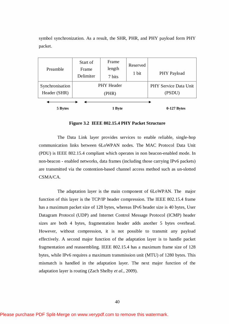
packet data structure of physical layer is presented in Figure 3.2. The PHY data
structure is divided into PHY header field and the PHY payload field. It consists of
Synchronisation Header (SHR), PHY Header (PHR) and Physical Service Data Unit
(PSDU). The Synchronisation header encompasses various fields: Preamble
Sequence, Start of Frame Delimiter, and a Frame length field. The Physical header
is the reserved field indexed with one bit. The SHR condones the receiver to achieve
Please purchase PDF Split-Merge on www.verypdf.com to remove this watermark.
40
symbol synchronization. As a result, the SHR, PHR, and PHY payload form PHY
packet.
Preamble Start of Frame
Delimiter
Frame length
7 bits
Reserved
1 bit
PHY Payload
Synchronisation Header (SHR)
PHY Header
(PHR) PHY Service Data Unit
(PSDU)
Figure 3.2 IEEE 802.15.4 PHY Packet Structure
The Data Link layer provides services to enable reliable, single-hop
communication links between 6LoWPAN nodes. The MAC Protocol Data Unit
(PDU) is IEEE 802.15.4 compliant which operates in non beacon-enabled mode. In
non-beacon - enabled networks, data frames (including those carrying IPv6 packets)
are transmitted via the contention-based channel access method such as un-slotted
CSMA/CA.
The adaptation layer is the main component of 6LoWPAN. The major
function of this layer is the TCP/IP header compression. The IEEE 802.15.4 frame
has a maximum packet size of 128 bytes, whereas IPv6 header size is 40 bytes, User
Datagram Protocol (UDP) and Internet Control Message Protocol (ICMP) header
sizes are both 4 bytes, fragmentation header adds another 5 bytes overhead.
However, without compression, it is not possible to transmit any payload
effectively. A second major function of the adaptation layer is to handle packet
fragmentation and reassembling. IEEE 802.15.4 has a maximum frame size of 128
bytes, while IPv6 requires a maximum transmission unit (MTU) of 1280 bytes. This
mismatch is handled in the adaptation layer. The next major function of the
adaptation layer is routing (Zach Shelby et al., 2009).
5 Bytes 0-127 Bytes 1 Byte
Please purchase PDF Split-Merge on www.verypdf.com to remove this watermark.

41
The 6LoWPAN network layer provides the internetworking capability to
sensor nodes. The main considerations of this layer are addressing, mapping and
routing protocols. It addresses IPv6 requirement and provides appropriate security
services. It also supports routing and network management with SNMP (Simple
Network Management Protocol). In 6LoWPAN, being based on the process of
packet forwarding, the routing is classified into two schemes such as mesh-under
and route-over. The decision of routing occurs in 6LoWPAN adaptation layer. On
the other hand, in Route-over, the decision is executed in 6LoWPAN network layer.
In route-over scheme, each link layer hop is an IP hop and each node acts as IP
router. The packet is forwarded hop by hop from source to destination between these
links. The payload packet is encapsulated with IP header. Later, IP packet is
fragmented and is sent to the next hop node based on routing table information.
when the adaptation layer in the next hop receives all the fragments successfully, it
creates an IP packet from fragments and forwards it to the network layer. Further,
the network layer sends the packet to the upper layer (transport layer), conditional to
the desired destination being reached. Otherwise, it forwards the packet to the next
hop node according to the routing table information. Whenever fragment
loss is encountered, all fragments are retransmitted to one hop distance (Jonathan
Hui et al., 2009).
Similar to the transport layer in OSI model, 6LoWPAN transport layer is
responsible for process-to-process delivery. It delivers data segment to the
appropriate application process on the sensor node. In this layer, there are two types
of transport protocols namely User Datagram Protocol (UDP) and Transmission
Control Protocol (TCP). At the source side, either TCP or UDP connections is
established based on the application. Hence, either TCP or UDP processes is
created. The data from application layer is organized in either UDP or TCP segment
and attached to created process (Zach Shelby et al., 2009). On the destination side,
after the UDP or TCP segments is received from the network layer, the transport
layer processes the segment, based on the protocol used and sends it up to the
application layer. However, in order to enhance the use of limited resource of
Please purchase PDF Split-Merge on www.verypdf.com to remove this watermark.

42
6LoWPAN, UDP protocol is commonly used. In aspect of performance, efficiency
and complexity, TCP is not preferably used with 6LoWPAN.
The 6LoWPAN application layer uses a socket interface for a specific
application as shown in the Figure 3.3. Each 6LoWPAN application opens a socket
to receive or send packets. Each socket is associated with a protocol such as
TCP or UDP, and Ports namely source and destination ports (Nurul halimatul
Asmak Ismail et al., 2012).
Application N
Socket API
Transport Layer
Figure 3.3 6LoWPAN Applications using a Socket Interface
Basically, 6LoWPAN is a collection of IP-enabled sensor nodes which are
assigned IPv6 addresses by an Edge Router (ER). For a mobile sensor, these IPv6
addresses are valid as long as they are within the range of ER. The association and
disassociation of nodes are similar to that of WLAN (Wireless Local Area
Network). The architecture of 6LoWPAN is illustrated in Figure 3.4, which consists
of three types of 6LoWPAN such as simple LoWPAN, Extended LoWPAN and Ad
hoc LoWPAN. In Simple LoWPAN, nodes are connected to the Internet via a Edge
Router (ER) (Zach Shelby et al., 2009). To address the network scalability multiple
ERs can be used resulting in an Extended LoWPAN. An Ad hoc LoWPAN operates
without an infrastructure and is connected to the Internet. In this topology, a router
is randomly configured to act as a simplified ER. This ER does the unique local
Unicast Address Generation (ULA) and also handles 6LoWPAN Neighbour
Discovery registration functionality. The ER placed at the edge of the 6LoWPAN
routes traffic in and out of the 6LoWPAN and handles neighbour discovery and
header compression task.
Please purchase PDF Split-Merge on www.verypdf.com to remove this watermark.

43
This thesis focuses on the Simple LoWPAN. The nodes in 6LoWPAN
plays the role of host or router, along with one or more edge routers. The network
interfaces of the nodes in a LoWPAN share the same IPv6 prefix which is
distributed by the ER and routers throughout the LoWPAN. In order to facilitate
efficient network operation, nodes initially make a registration with an edge router.
These operations are part of Neighbour Discovery (ND). ND defines interaction of
hosts with routers. Nodes are free to move throughout the LoWPAN, between edge
routers, and even between LoWPANs maintaining a multi-hop mesh topology. In
traditional WSN, the lower layers (PHY&MAC) are standardized by IEEE 802.15.4,
while the upper layers are by zigbee standard (Zach Shelby et al., 2009).
Figure 3.4 Architecture of 6LoWPAN
Please purchase PDF Split-Merge on www.verypdf.com to remove this watermark.
44
3.3 FEATURES OF 6LoWPAN
3.3.1 IEEE 802.15.4
IEEE 802.15.4 is a standard for low-power, low data rate wireless
communication between small nodes. It forms the basis for Low Rate, Wireless
Personal Area Networks (LR-PANs). It supports a much broader range of
applications. Also it provides cheap, low power, short-range communications for
embedded nodes. It addresses the lower layer such as MAC and PHY layer function
activities. The four types of frame formats specified by Zigbee standard are Beacon
Frame, MAC Command Frame, Data Frame and ACK Frame (Montenegro et al.,
2007). Data frames are used to transport the actual data, which are IPv6 frames
packaged according to 6LoWPAN format specifications. Acknowledgment frames
are used by the receiver after the successful reception of the data frame. MAC layer
command frames are used to enable various MAC layer services such as association
and disassociation from a co-ordinator and also for the management of synchronised
transmission. The upper layer functionalities are handled by Zigbee standard which
is developed by Zigbee Alliance Consortium (Zach Shelby et al., 2009).
Wireless Sensor Networks can be either beacon enabled or non-beacon
enabled. In beacon-enabled networks, the PAN (Personal Area Network)
coordinator sends a beacon frame to synchronize and delineate Super frames. Here
access to the channel is slotted and Super frames contain Guaranteed Time Slots
(GTS), each of which are assigned to a specific node, preventing media access
contention. Beacon-enabled networks are energy efficient as the nodes that do not
have a slot can be switched to 'sleep' mode from 'listen' mode (Montenegro et al.,
2007). In non-beacon enabled networks, no beacon frames are transmitted by the
coordinator. Hence all nodes would be in 'listening' mode keeping their radios ON.
IEEE 802.15.4 supports both the 64-bit extended address or 16-bit unique address
within the PAN (Montenegro et al., 2007).
Please purchase PDF Split-Merge on www.verypdf.com to remove this watermark.
45
3.3.2 6LoWPAN Network Topologies
6LoWPAN supports both star and mesh topology (Zach Shelby et al.,
2009). However most of the 6LoWPAN applications such as automatic meter
reading and environmental monitoring have been developed using mesh topologies.
As it is often coverage extended and cost-effective with respect to infrastructure, it
adopts multi-hop forwarding to achieve energy efficiency. This can be done in three
different ways such as link-layer mesh, LoWPAN mesh or IP routing. Link layer
mesh and LoWPAN mesh are referred to as Mesh-under as the mesh forwarding is
transparent to the Internet Protocol. IP routing is referred to as route-over.
The most common routing employed in 6LoWPAN is IP routing. An
algorithm present in the router updates the routing table based on which next hop
node is selected. The Internet protocol just forwards the packets. The IETF MANET
WG (Working Group) for generic ad hoc networks has developed IP routing
algorithms for mesh networking. While IETF ROLL WG has developed, specific
routing algorithm for wireless embedded applications such as industrial and building
automation.
3.3.3 6LoWPAN Addressing and Auto Configuration
6LoWPAN supports Stateless Address Auto configuration (SAA)
mechanism which reduces the configuration overhead on the nodes. The auto
configuration process includes generation of link local address and global address.
Further, it also performs Duplicate Address Detection (DAD) procedure to verify
the unique nature of the addresses on a link.
The stateless method is used, when the consideration for the exact
addresses that the nodes use are taken in a random manner. While Dynamic Host
Configuration Protocol for IPv6 (DHCPv6) (Droms et al., 2003) is used when there
is a strong consideration for exact address assignments. Both methods can be used
simultaneously.
Please purchase PDF Split-Merge on www.verypdf.com to remove this watermark.

46
To test the unique nature of the address on a given link, nodes run
Duplicate Address Detection (DAD) algorithm on addresses before assigning them
to an interface. This DAD algorithm is performed on all addresses even if they are
obtained through DHCPv6 or stateless auto configuration. This auto configuration
process is applied only to nodes and not to routers. The advantage of stateless
address auto configuration includes the reduction of manual configuration of
individual nodes.
3.3.4 The Need for Adaptation Layer
The 6LoWPAN WG has defined the IPv6 communication among 802.15.4
frames with the help of the adaptation layer. Three main functions of the adaptation
layer are header compression, fragmentation and layer-2 forwarding. The
6LoWPAN adaptation layer uses stateless compression which compresses the
overlapping values of adaptation, network and transport layer header fields to a few
bytes.
Single hop, no fragmentation
IEEE 802.15.4 header IPv6 header
compression Payload
Single hop, fragmentation
IEEE 802.15.4
header
Fragment
header
IPv6 header
compression Payload
Multi-hop, fragmentation
IEEE
802.15.4
header
Mesh
addressing
header
Fragment
header
IPv6 header
compression Payload
Figure 3.5 6LoWPAN Header Stack
Please purchase PDF Split-Merge on www.verypdf.com to remove this watermark.

47
In IEEE 802.15.4, MAC header, Mesh addressing header and IPv6
compressed header are all considered as IP addresses. Typical 6LoWPAN header
stack is shown in the Figure 3.5 (Jonathan Hui et al., 2009). It is found that no
fragmentation happens when the payload is IEEE 802.15.4 compatible. However,
when it exceeds, fragmentation happens and then fragmentation header is
introduced. In case of multihop routing to avoid medium contention, mesh
addressing header is introduced in the stack .
3.3.4.1 Fragment Header
In order to accommodate, payload of a large size in a single IEEE
802.15.4 frame, fragmentation header is used. It consist of three fields namely
Datagram Size, Datagram Tag and Datagram Offset as illustrated in Figure 3.6
(Montenegro et al., 2007).
Datagram size specifies the total size of the payload. It is included in
every fragment to simplify the buffer allocation at the receiver for proper payload
reassembly. Datagram tag identifies the set of fragments corresponding to a given
payload and it is used to map fragments of the same payload. Datagram offset
identifies the number of fragments that are offset within the un-fragmented payload.
1 1 0 Rsv Datagram size Datagram tag
Datagram offset
Figure 3.6 Fragment Header
3.3.4.2 Mesh addressing Header
To forward 6LoWPAN payloads over multiple radio hops and to support
layer-two forwarding, mesh addressing header is used. Figure 3.7 displays the frame
format of mesh addressing header. It includes three fields namely hop limit, source
address and destination address. The hop limit field limits the number of hops for
forwarding and is decremented by each forwarding . The frame is dropped when this
Please purchase PDF Split-Merge on www.verypdf.com to remove this watermark.

48
field is decremented up to zero. The end points of an IP hop is indicated by the
source and the destination address. Both source and destination addresses may be
either short address or extended address.
1 0 S D Hops
limit
Source address Destination address
Figure 3.7 Mesh Addressing Header
The payload length of the reassembled original packet is computed using
the expression given in equation (3.1) (Hinden and Deering, 2006).
8 8*org first first Last LastPL PL FL FO FL (3.1)
Where
PLorg = Payload length field of the reassembled packet
PLfirst = Payload length field of the first fragment packet.
FLfirst = Length of the fragment following first fragment header of first
fragment packet.
FOLast = Fragment offset field of fragment header of last fragment
packet.
FLLast = Length of fragment following fragment header of last fragment
packet.
3.4 ADDRESSING IN 6LoWPAN
The link layer address is not a routable address and it cannot predict the
nodes present in the network. In 6LoWPAN, data frames carry both the source and
the destination addresses (Montenegro et al., 2007). This destination address is used
by a receiver to decide whether the frame is actually intended for this receiver or
not. The source address plays a vital role in mesh forwarding. 6LoWPAN nodes are
Please purchase PDF Split-Merge on www.verypdf.com to remove this watermark.

49
permanently identified by Extended Unique Identifier (EUI)-64 identifier. Also it
defines a 16-bit short address format which is dynamically assigned during the
bootstrapping of the network. 6LoWPAN requires that both the source and
destination addresses be included in the frame header. Thus IPv6 addresses are
compressed in 6LoWPAN.
3.5 NEIGHBOUR DISCOVERY (ND)
6LoWPAN Neighbour Discovery (ND) describes network auto
configuration and operations of hosts, routers and edge routers in LoWPANs. ND is
used to bootstrap the whole LoWPAN. Bootstrapping is the process of assigning
IPv6 addresses to nodes that are within radio range to enable basic communication.
In order to reduce the cost involved in multicast flooding, a registry of the nodes in
each LoWPAN is maintained in the white board database of the Edge Router (ER).
Using Neighbour Discovery (ND) protocol each node present in the
LoWPAN discovers its neighbours as shown in the Figure 3.8. It also determines its
link-layer addresses, to find routers. ND helps to maintain reachability information
about the paths to neighbours that the node is actively communicating with others.
ND can be combined with other protocols such as DHCPv6 to obtain additional
node configuration information (Droms et al., 2003).
The ND protocol classifies the nodes into two category namely hosts and
routers. Host nodes are basically the source node, while router nodes are the
intermediate node that forward data to the destination. Edge router is considered to
be the destination node that interfaces with Internet to formulate 6LoWPAN.The
Edge router compared to other routers performs complex functions such as
maintaining the whiteboard database about the nodes and routers inside the
LoWPAN. Thus centralized administration is maintained by the Edge router (ER)
(Zach Shelby et al., 2009).
Please purchase PDF Split-Merge on www.verypdf.com to remove this watermark.

50
Figure 3.8 LoWPAN Neighbour Discovery
3.6 CHALLENGES IN 6LoWPAN
The advances in 6LoWPAN, while promising, have also posed challenges
in the area of IP connectivity, network topologies, limited packet size, limited
configuration and management, service and security discovery .These challenges
and tradeoffs are discussed as follows: (Kushalnagar et al., 2007).
3.6.1 IP Connectivity
The need for IP connectivity within a LoWPAN is realised by connecting
the sensor nodes to other IP-based networks or to embedded devices. As nodes in
the 6LoWPAN network increase, the necessity for network auto configuration and
statelessness is highly required which can be achieved through IPv6 as it offers 2128
bits of address.
Please purchase PDF Split-Merge on www.verypdf.com to remove this watermark.

51
With the limited packet size of LoWPAN, the IPv6 address format allows
inclusion of IEEE 802.15.4 addresses if desired. Simple interconnectivity to other IP
networks including the Internet is done by IPv6. However given the limited packet
size, headers for IPv6 and layers above must be compressed whenever it is required
based on the application (Zach Shelby, 2009).
3.6.2 Limited Packet Size
Applications developed using 6LoWPANs should support only small
packets as devised by IEEE 802.15.4. Hence routing protocols need to be designed
in a manner as specified by the IEEE 802.15.4 frame. Whenever the packet size
exceeds 127 bytes, it may pose challenges for low end 6LoWPAN nodes, as they do
not have enough RAM or storage to accommodate 1280 sized packet.
3.6.3 Limited Configuration and Management
Nodes within the LoWPAN can be deployed in large numbers. Also these
LoWPAN devices posses limited input and display capabilities. Also the location of
some of these devices are hard to access. However, protocols used in LoWPANs
should have minimal configuration, be easy to bootstrap, and enable the network to
self heal given the inherent unreliable characteristic of these nodes. The size
constraints of the link layer protocol should also be considered. Network
management should have little overhead, yet be powerful enough to control dense
deployment of nodes in the network (Kushalnagar et al., 2007).
3.6.4 Service Discovery and Security consideration
6LoWPANs require service discovery network protocol to discover,
control and maintain services provided by nodes. New protocols must be designed
to enable such features in the nodes.
Please purchase PDF Split-Merge on www.verypdf.com to remove this watermark.

52
6LoWPANs applications require confidentiality and integrity protection,
which is provided by all the layers above the PHY layer. Some of the prevailing
constraints that will affect the choice of a particular protocol includes its small code
size, low power operation, low complexity and small bandwidth requirements.
3.6.5 Localization
The purpose of localization is the provision of some kind of location
information to the nodes in the network. Using the location knowledge of nodes, the
place of occurrence of the phenomenon can be easily determined. Further, it also
helps in developing energy efficient routing algorithms.
This research work considers location information along with the IP
address to reduce the overhead of the transmission. Several restrictions of
6LoWPAN networks include its limited energy supply, computing power and
bandwidth of the wireless links. 6LoWPAN networks poses certain challenges such
as the failure of node due to lack of power, physical damage or environmental
interference leading to rerouting or re-organisation of the network.
3.7 ZIGBEE
6LoWPANs are formed by nodes that are compatible with the IEEE
802.15.4 standard. However, Zigbee uses the IEEE 802.15.4 standard as its
communication protocol for Medium Access Control (MAC) layer and Physical
(PHY) layer. IEEE 802.15.4 nodes are characterized by low computational power,
scarce memory capacity, low bit rate, short range, and low cost (Vinay Kumar and
Sudharshan Tiwari, 2012).
3.7.1 Zigbee
Zigbee technology is characterized by low data rate, low power
consumption, and low cost. The networking protocol is mainly targeted towards
automation and remote control applications. Zigbee is initiated and maintained by
the Zigbee Alliance, which is responsible for the Zigbee technology standardisation.
Please purchase PDF Split-Merge on www.verypdf.com to remove this watermark.

53
The IEEE 802.15.4 task group and Zigbee Alliance worked together and developed
the technology commercially known as Zigbee (Zigbee Alliance, 2008).
Zigbee supports three types of nodes called Zigbee Co-ordinator (ZC),
Zigbee Router (ZR) and Zigbee End Device (ZED).The Zigbee Co-ordinator
maintains and co-ordinates the entire network with overall network knowledge. The
Zigbee Router (ZR) works as a router in the network to forward data. The Zigbee
End Device (ZED) has limited functionalities such as sensing and reporting data to
the ZR.
The main goal of the Zigbee technology is to enable WSNs composed of
large number of nodes to function with reduced energy consumption. Various sensor
nodes like Mica Motes, TelosB uses Zigbee to achieve higher life time for their
applications (Zigbee Alliance, 2005).
3.7.2 Zigbee Architecture
The Zigbee stack architecture is shown in the Figure 3.9. Zigbee stack
does not exactly match within the OSI (Open System Interconnection) seven layer
networking model, but it has some of the same elements including the PHY, MAC
and Network layers. Layers 4 through 7 (transport, session, presentation and
application) are wrapped in the Application Support Layer (APS) and Zigbee
Device Object (ZDO) layers in the Zigbee model (Zigbee Alliance).
The PHY and MAC layers are defined by the IEEE 802.15.4 standard
specification. The PHY layer simply translates packets over the air. The PHY layer
can operate at two frequencies 868/915 MHz and 2.4 GHz with 16 channels and 250
Kbps of maximum transmission rate as given in Table 3.2.
The MAC layer provides commands for association and disassociation,
acknowledged frame delivery, channel access mechanism, frame validation,
guaranteed time slot management and beacon management. The application and
network layers are defined by the (Zigbee Alliance, 2005), while PHY and MAC
layers are defined by the IEEE 802.15.4 standard (Jonathan Hui et al., 2009). The
Please purchase PDF Split-Merge on www.verypdf.com to remove this watermark.

54
Network layer does mesh networking by broadcasting packets across the network,
determining routes for unicasting packets and for ensuring reliability.
Zigbee networks are all secured at the network layer and the entire
payload of the network frame is encrypted. The Application Support Layer (APS)
acts as a filter for the applications running above it and on the end points to simplify
the logic in those applications. The ZDO layer is responsible for local and over the
air management of the network. It provides services to discover other nodes in the
network and is responsible for the current state of the network.
The Application framework contains the Zigbee cluster library and
provides a framework to run the application. Endpoints mechanism distinguish one
application from another. Between the layers, there are Service Access Points
(SAP), which provide an Application Program Interface (API) that isolates the inner
workings of that layer from the layer above and below. Zigbee uses two SAP
approach per layer, one for data and one for management. All the data
communications to and from the network layer go through the Network Layer Data
Entity Service Access Point (NLDE-SAP).
ZIGBEE DEVICE OBJECT (ZDO)
APPLICATION SUPPORT LAYER (APS)
NETWORK LAYER
MAC LAYER
PHYSICAL LAYER
Figure 3.9 The Zigbee Stack Architecture
Zigbee technology differs from other wireless technologies due to its data
transmission rate, low energy consumption, lower cost, higher self organisation and
more flexible network topologies.
Please purchase PDF Split-Merge on www.verypdf.com to remove this watermark.

55
3.7.3 Zigbee Network Topology
Three kinds of network topologies are supported by Zigbee technology. They are Star, peer-to-peer and Cluster tree as shown in Figure 3.10. In the star topology, communication is established between the devices and a single node controller, called the PAN coordinator. The PAN coordinator is mains powered, while the other nodes are battery powered. The Star topology is the simplest topology and is based on a many-to-one communication paradigm. Here all the nodes are covered by the PAN co-ordinator antenna and are able to send the messages in one hop.
In contrast to star topology, any device can communicate with any other device in peer-peer topology so long as they are within range of one another. A peer-to-peer network can be ad hoc, self-organising and self-healing (Zigbee Alliance, 2005).
Cluster-tree topology is a special case of peer-to-peer network, in which most of the devices are Full Function Device (FFD) and a Reduced Function Device (RFD) may connect to a cluster tree network as a leaf node at the end of a branch. The advantage of the clustered structure is increased coverage at the cost of increased message latency (Mohamed Matin, 2012).
Figure 3.10 Network Topologies of Zigbee
Please purchase PDF Split-Merge on www.verypdf.com to remove this watermark.
56
Peer-to-Peer and Cluster tree topologies rely on a routing protocol in order
to deliver the messages to the PAN co-ordinator. Peer-to-peer topology does not
allow cluster heads and nodes to communicate with each other. Cluster tree
topology is based on the organisation of nodes into clusters. Star topology is
considered the simplest because simple routing solutions can be developed.
3.8 FEATURES OF ZIGBEE
3.8.1 Reliability
Radio waves can be interrupted by many factors such as metal, concrete or
dependent on the antenna design, power amplification and even weather condition.
In case of wireless environment, the propagation medium should be dynamic and
uncertain imposing limitation on coverage area. Therefore small changes in the
position or direction of the signal may result in the drastic differences of the signal
strength or the quality of the link (Zigbee Alliance, 2008). To adhere to this
challenge, Zigbee technology takes counter measures to provide reliability. It relays
on the data only on the reliable path that are IEEE 802.15.4 complaint. Before
transmitting, nodes listen to the channel, unless the channel is idle, it begins to
transmit. This prevents collision within the channel, reducing data loss. Also Zigbee
uses a 16-bit Cyclic Redundancy Check (CRC) on each packet, called a Frame
Checksum (FCS) to ensure that the data bits are correct. Here each packet is retried
up to three trials.
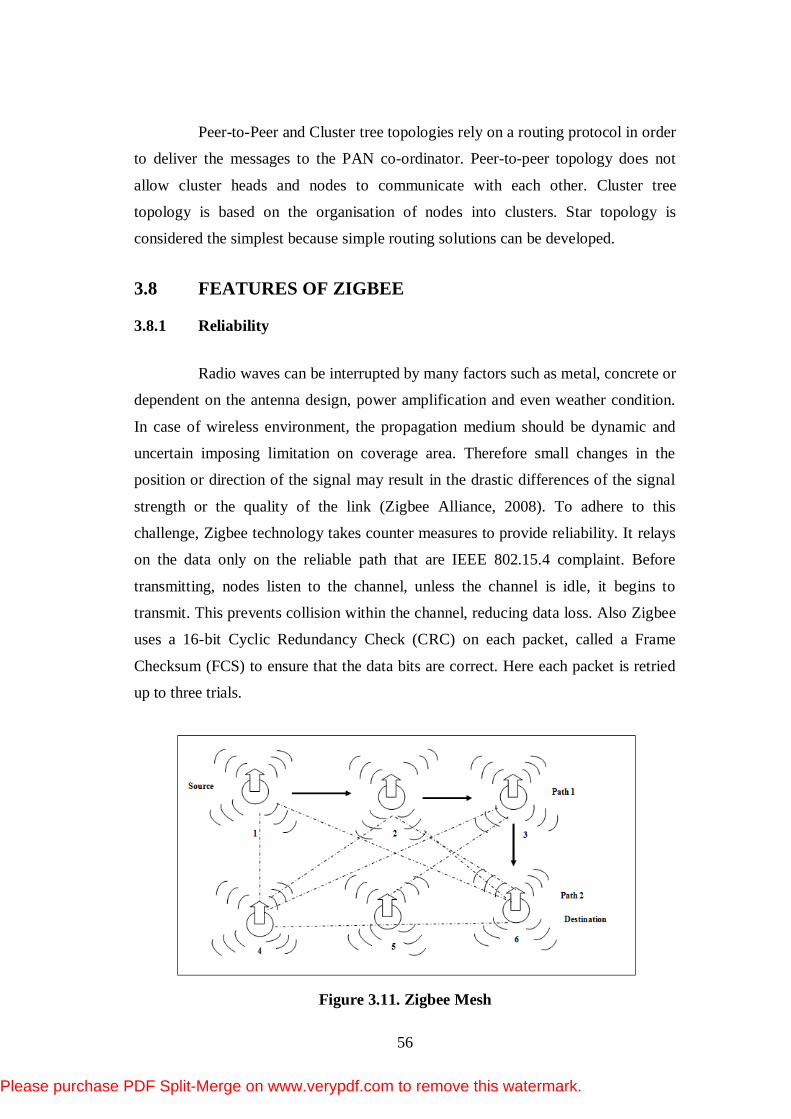
Figure 3.11. Zigbee Mesh
Please purchase PDF Split-Merge on www.verypdf.com to remove this watermark.
57
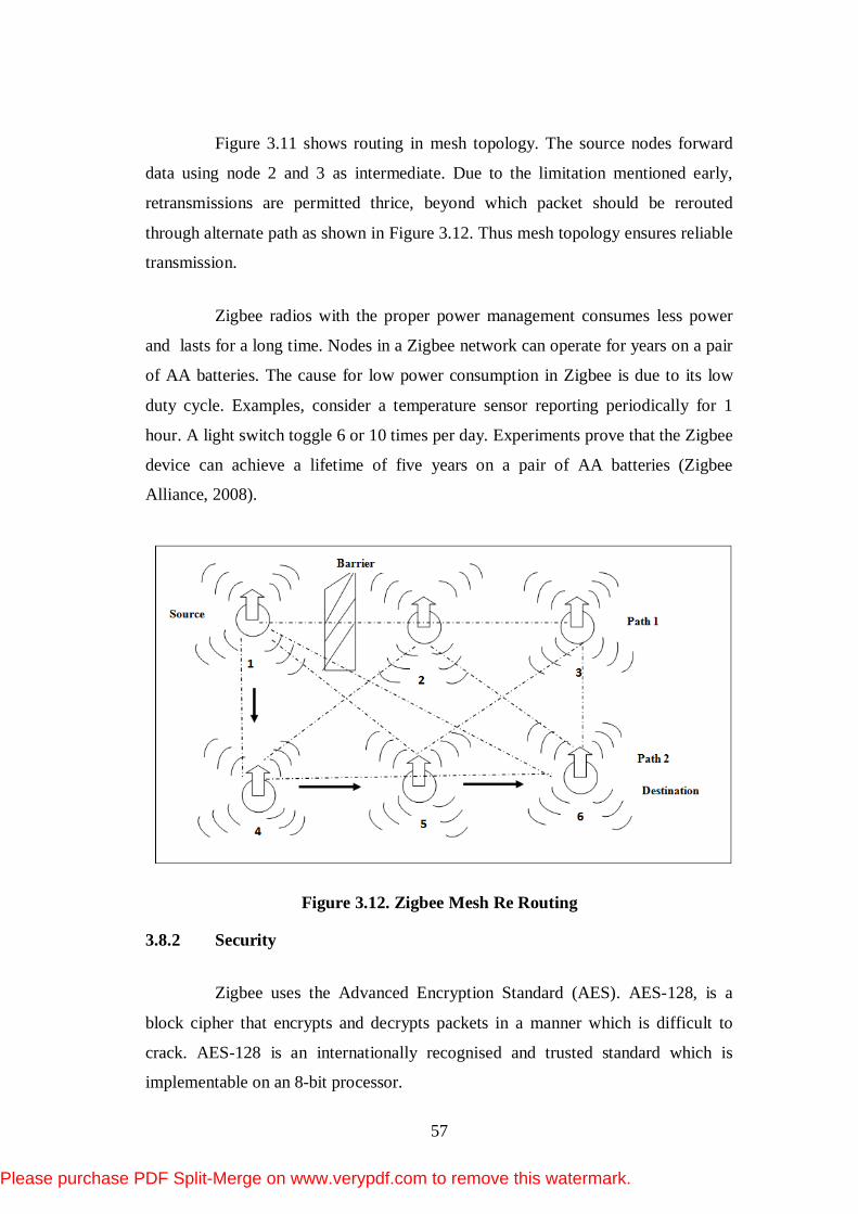
Figure 3.11 shows routing in mesh topology. The source nodes forward
data using node 2 and 3 as intermediate. Due to the limitation mentioned early,
retransmissions are permitted thrice, beyond which packet should be rerouted
through alternate path as shown in Figure 3.12. Thus mesh topology ensures reliable
transmission.
Zigbee radios with the proper power management consumes less power
and lasts for a long time. Nodes in a Zigbee network can operate for years on a pair
of AA batteries. The cause for low power consumption in Zigbee is due to its low
duty cycle. Examples, consider a temperature sensor reporting periodically for 1
hour. A light switch toggle 6 or 10 times per day. Experiments prove that the Zigbee
device can achieve a lifetime of five years on a pair of AA batteries (Zigbee
Alliance, 2008).
Figure 3.12. Zigbee Mesh Re Routing
3.8.2 Security
Zigbee uses the Advanced Encryption Standard (AES). AES-128, is a
block cipher that encrypts and decrypts packets in a manner which is difficult to
crack. AES-128 is an internationally recognised and trusted standard which is
implementable on an 8-bit processor.
Please purchase PDF Split-Merge on www.verypdf.com to remove this watermark.

58
3.8.3 Low Data Rate
Zigbee resides on transceivers, which operate at 2.4 GHz offering a data
rate of 250 Kbps.
3.9 ZIGBEE Vs 6LoWPAN
6LoWPANs are formed by devices that are compatible with the IEEE
802.15.4 standard. Zigbee is a network layer protocol whose PHY and MAC layer is
based on the IEEE 802.15.4 standard to achieve the goal of low-power and low-
energy consumption as given in Table 3.2 (Zigbee Alliance, 2005). IEEE 802.15.4
devices are characterized by low computational power, scarce memory capacity, low
bit rate, short range and low cost. Zigbee provides license-free operations, huge
spectrum allocation and worldwide compatibility. Zigbee is more suitable for WSN,
mainly because of its low power consumption derived from its multi-hop
communication.
The power consumption in a sensor network is of primary importance and
it should be extremely low. The Zigbee protocol places primary importance on
power management. It has been developed to allow low power consumption and
years of battery life. Zigbee is limited to a single radio standard whereas 6LoWPAN
is applicable to any low-power, low-rate wireless radio or even wired. IP protocols
tie together heterogeneous networks. Zigbee is based on small scale isolated ad hoc
networking. LoWPAN has devices that work together to connect the physical
working environment to real world applications like sensors with wireless
application. Some protocols exist in sensor networks that have a non-IP network
layer protocol such as Zigbee, where the TCP/IP protocol is not used. However
6LoWPAN provides a WSN node with IP communication capabilities by putting an
adaptation layer above the IEEE 802.15.4 for the packet fragmentation and
reassembly purpose.
Please purchase PDF Split-Merge on www.verypdf.com to remove this watermark.

59
6LoWPAN is massively scalable, networking as an end-to-end part of the
Internet, its IPv6. IPv6 is designed for large scale enterprise automation, M2M,
metering system etc., which require end-to-end addressing, security, mobility, traffic
multiplexing, reusability, maintainability and web services which are globally
scalable.
Many standard and proprietary protocols like Zigbee, MiWi mesh and
MiWi P2P, Wireless Hart and ISA 100.11a use the MAC and PHY (circuits) in
association with IEEE 802.15.4 radios. They use their own arrangements of bits and
bytes to transfer information between nodes, but none of them use the IP. So they
cannot directly communicate with Internet based devices and web servers/ browsers.
To accommodate the IPv6 MTU size of 1280 bytes into 802.15.4 frame of
127 bytes stateless compression is done, which gives nodes the flexibility to
communicate with any neighbour in compressed form at all times.
Stateless compression gives a network multiple entry and exit points,
whereas a stateful network is susceptible to single point failures. As a result of
stateless compression, the 6LoWPAN community has software stacks with a
minimal memory requirement compared to a Zigbee stack. The beauty of
6LoWPAN communication is that they let people communicate with nodes across
the Internet without Zigbee gateway. 6LoWPAN communications do not require a
complete modifications in the IEEE 802.15.4 radio stack, instead it adds an
adaptation layer at the top of the MAC layer for effective data delivery among the
nodes.
Please purchase PDF Split-Merge on www.verypdf.com to remove this watermark.
60
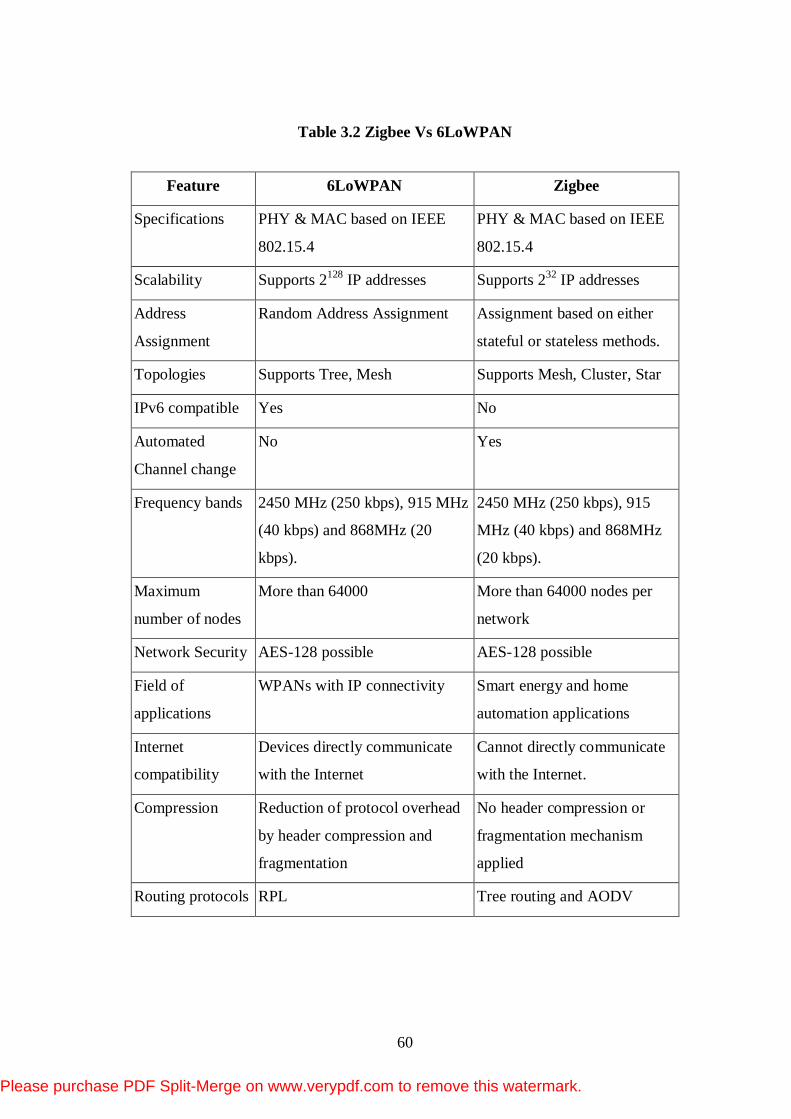
Table 3.2 Zigbee Vs 6LoWPAN
Feature 6LoWPAN Zigbee
Specifications PHY & MAC based on IEEE
802.15.4
PHY & MAC based on IEEE
802.15.4
Scalability Supports 2128 IP addresses Supports 232 IP addresses
Address
Assignment
Random Address Assignment Assignment based on either
stateful or stateless methods.
Topologies Supports Tree, Mesh Supports Mesh, Cluster, Star
IPv6 compatible Yes No
Automated
Channel change
No Yes
Frequency bands 2450 MHz (250 kbps), 915 MHz
(40 kbps) and 868MHz (20
kbps).
2450 MHz (250 kbps), 915
MHz (40 kbps) and 868MHz
(20 kbps).
Maximum
number of nodes
More than 64000 More than 64000 nodes per
network
Network Security AES-128 possible AES-128 possible
Field of
applications
WPANs with IP connectivity Smart energy and home
automation applications
Internet
compatibility
Devices directly communicate
with the Internet
Cannot directly communicate
with the Internet.
Compression Reduction of protocol overhead
by header compression and
fragmentation
No header compression or
fragmentation mechanism
applied
Routing protocols RPL Tree routing and AODV
Please purchase PDF Split-Merge on www.verypdf.com to remove this watermark.

61
3.10 NEED FOR ROUTING IN 6LoWPAN
Routing can be referred to as a technique by which information is
transferred from one place to another. 6LoWPAN architecture enables the
transmission of IPv6 over WSNs based on the IEEE 802.15.4 standard. Various
requirements of this technology support sleep/listen mode, low overhead on data
packets and minimal computation and energy requirements. Packets have to traverse
multiple radio hops on their way through the 6LoWPAN. This involves two
processes namely routing and forwarding. 6LoWPAN supports routing in both layer
2 and layer 3. If it happens in layer2, it is called mesh-under. In layer3, it is called
route-over (Aminul Haque et al., 2009).
Routing is challenging for 6LoWPAN, with low-power and lossy radio
links, battery powered nodes, multi-hop mesh topologies and frequent topological
changes due to mobility. Two kinds of routing can be performed with 6LoWPAN,
Intra -LoWPAN routing between LoWPAN routers, and border routing performed at
the edge of the LoWPAN by the LoWPAN edge router or an IPv6 router on the
backbone link for Extended LoWPANs (Zach Shelby and Carsten Bormann, 2009).
IP networks are packet switched and so forwarding decisions are made
hop-by-hop, based on the destination address in a packet. IP addresses are
structured, so as to be used to group together addresses under a single route entry. In
IPv6 an address prefix is used for this purpose, so it is called prefix based routing.
However this work focuses on routing in 6LoWPAN which is dealt with in detail in
next section.
This chapter has given an insight about 6LoWPAN basics and its
architecture. In the next section, the detailed information about the 6LoWPAN
routing protocols are presented.
Please purchase PDF Split-Merge on www.verypdf.com to remove this watermark.