CHAPTER 3 1. THE OSI MODEL AND THE TCP/IP PROTOCOL SUITE Outline: 1. Protocol Layers 2. OSI Model...
33
CHAPTER 3 1
-
Upload
beryl-harrison -
Category
Documents
-
view
244 -
download
3
Transcript of CHAPTER 3 1. THE OSI MODEL AND THE TCP/IP PROTOCOL SUITE Outline: 1. Protocol Layers 2. OSI Model...

1
CHAPTER 3

2
THE OSI MODEL AND THE TCP/IP PROTOCOL SUITE
Outline:
1. Protocol Layers
2. OSI Model
3. TCP/IP Model
4. Addressing
OBJECTIVES
To discuss the OSI model and its layer architecture and to show the interface between the layers.
To briefly discuss the functions of each layer in the OSI model.
To introduce the TCP/IP protocol suite and compare its layers with the ones in the OSI model.
To show the functionality of each layer in the TCP/IP protocol with some examples.
To discuss the addressing mechanism used in some layers of the TCP/IP protocol suite for the delivery of a message from the source to the destination.
3

COMPUTER NETWORK COMPONENTS
Components of a computer network: Computer (PCs, laptops, handhelds)
routers & switches (IP router, Ethernet switch)
Links” Transmission media” (wired, wireless)
protocols (IP,TCP,CSMA/CD,CSMA/CA)
applications (network services)i.e. Network Operating System (NOS)
humans and service agents
4
PROTOCOL LAYERS
We discussed that a protocol is required when two entities need to communicate.
When communication is not simple, we may divide the complex task of communication into several layers.
Let us use a scenario in communication in which the role of protocol layering may be better understood.
We use two examples. In the first example, communication is so simple that it can occur in only one layer.
5
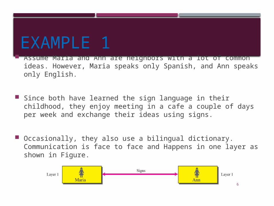
EXAMPLE 1 Assume Maria and Ann are neighbors with a lot of common ideas.
However, Maria speaks only Spanish, and Ann speaks only English.
Since both have learned the sign language in their childhood, they enjoy meeting in a cafe a couple of days per week and exchange their ideas using signs.
Occasionally, they also use a bilingual dictionary. Communication is face to face and Happens in one layer as shown in Figure.
6

EXAMPLE 2 Now assume that Ann has to move
to another town because of her job. Before she moves, the two meet for the last time in the same cafe.
Although both are sad, Maria surprises Ann when she opens a packet that contains two small machines.
• The first machine can scan and transform a letter in English to a secret code or vice versa.
• The other machine can scan and translate a letter in Spanish to the same secret code or vice versa.
Ann takes the first machine; Maria keeps the second one.
The two friends can still communicate using the secret code, as shown in Figure.
7

PROTOCOL LAYERS
Network activity involves sending data from one computer to another. This complex process can be broken into discrete, sequential tasks. The sending computer must:
Recognize the data.
Divide the data into manageable chunks.
Add information to each chunk of data to determine the location of the data and to identify the receiver.
Add timing and error-checking information.
Put the data on the network and send it on its way.
In this case, we may need several protocols, one for each layer. 8

THE OSI MODEL• In 1978, the International Organization for Standardization
(ISO) released a set of specifications that described network architecture for connecting dissimilar devices.
• Established in 1947, the International Standards Organization (ISO) is a multinational body dedicated to worldwide agreement on international standards.
• Almost three-fourths of countries in the world are represented in the ISO.
• An ISO standard that covers all aspects of network communications is the Open Systems Interconnection (OSI) model.
9
10
ISO is the organization; OSI is the model.
Note

TOPICS DISCUSSED IN THE SECTION
Layers in the OSI Model
Layered Architecture
Layer-to-layer Communication
Encapsulation
11
OSI MODEL LAYERS
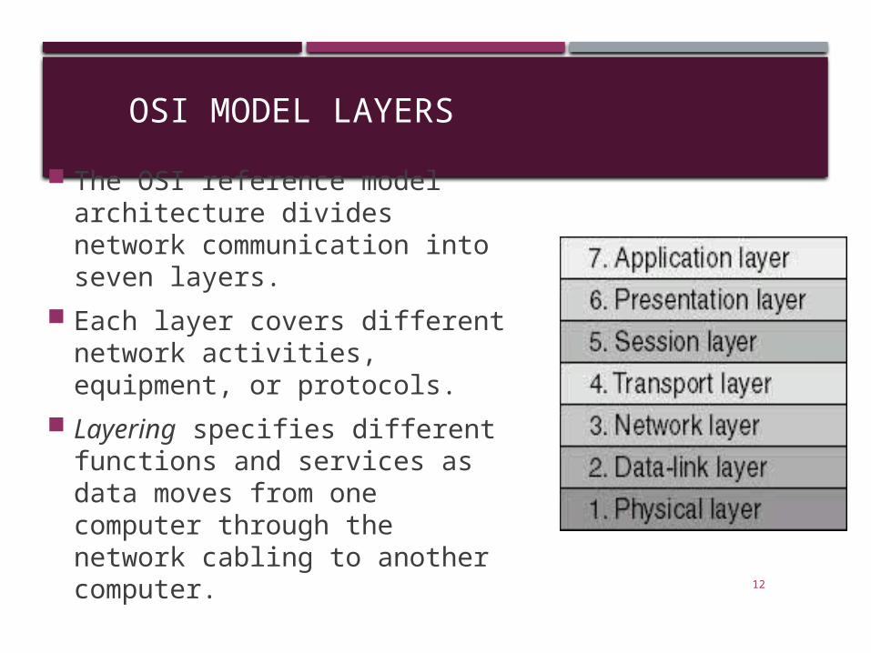
The OSI reference model architecture divides network communication into seven layers.
Each layer covers different network activities, equipment, or protocols.
Layering specifies different functions and services as data moves from one computer through the network cabling to another computer. 12
OSI MODEL LAYERS
Each layer provides some service or action that prepares the data for delivery over the network to another computer.
The lowest layers—1 and 2—define the network's physical media and related tasks, such as putting data bits onto the network interface cards (NICs) and cable.
The highest layers define how applications access communication services.
The higher the layer, the more complex its task.13
14
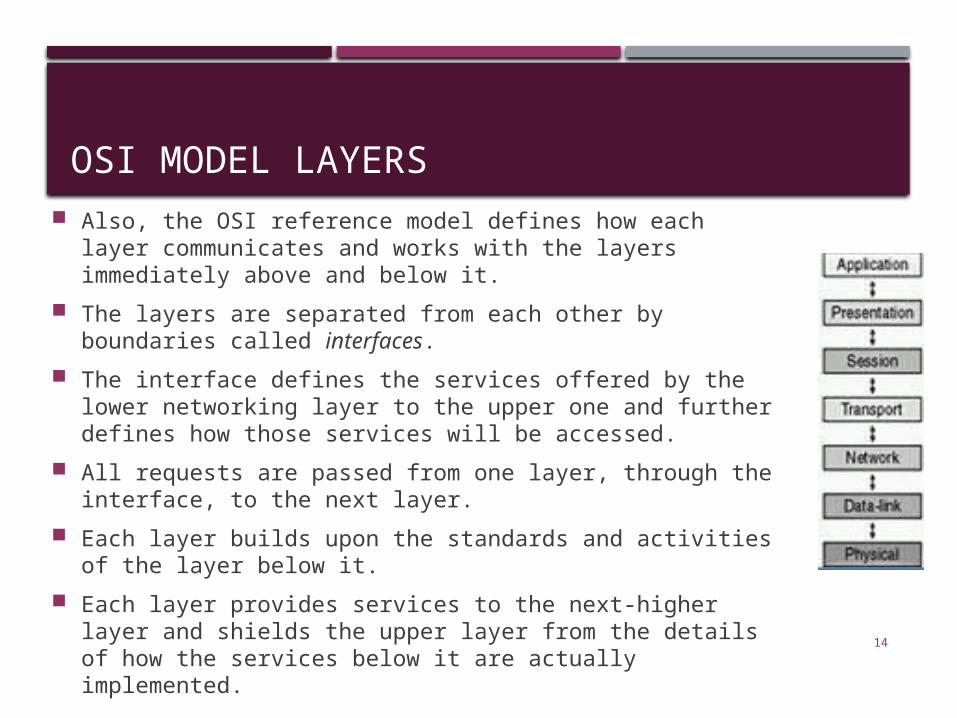
OSI MODEL LAYERS Also, the OSI reference model defines how each layer
communicates and works with the layers immediately above and below it.
The layers are separated from each other by boundaries called interfaces.
The interface defines the services offered by the lower networking layer to the upper one and further defines how those services will be accessed.
All requests are passed from one layer, through the interface, to the next layer.
Each layer builds upon the standards and activities of the layer below it.
Each layer provides services to the next-higher layer and shields the upper layer from the details of how the services below it are actually implemented.

15
OSI layers

OSI MODEL LAYERS
With the exception of the lowest layer in the OSI networking model, no layer can pass information directly to its counterpart on another computer. Instead, information on the sending computer must be passed down through each successive layer until it reaches the physical layer.
The information then moves across the networking cable to the receiving computer and up that computer's networking layers until it arrives at the corresponding layer. 16

OSI MODEL LAYERS But, we can visualize that each layer has a direct
communication with its associated layer on the other computer. This provides a logical, or virtual, communication between peer layers
17

18
An exchange using the OSI model ( Encapsulation)

ENCAPSULATION Before data is passed from one layer to another, it is broken
down into packets, or units of information, which are transmitted as a whole from one device to another on a network.
At the sender, each layer adds additional formatting or addressing to the packet, which is needed for the packet to be successfully transmitted across the network.
At the receiving end, the packet passes through the layers in reverse order. Each layer reads the information on the packet, strips it away, and passes the packet up to the next layer.
When the packet is finally passed up to the application layer, the packet is in its original form, which is readable by the receiver.
19
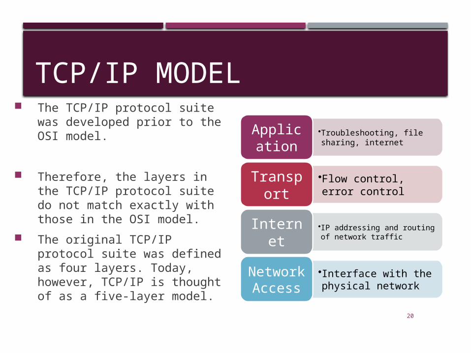
TCP/IP MODEL The TCP/IP protocol suite was
developed prior to the OSI model.
Therefore, the layers in the TCP/IP protocol suite do not match exactly with those in the OSI model.
The original TCP/IP protocol suite was defined as four layers. Today, however, TCP/IP is thought of as a five-layer model.
•Troubleshooting, file sharing, internet
Application
•Flow control, error control
Transport
•IP addressing and routing of network traffic
Internet
•Interface with the physical network
Network Access
20

21
COMPARISON BETWEEN OSI AND TCP/IP
IOS Model
Application
Presentation
Session
Transport
Network
Data Link
Physical
TCP/IP Model
Application
Transport
Internet
Network Access

22
LAYERS IN THE OSI MODELIN THIS SECTION WE BRIEFLY DESCRIBE THE FUNCTIONS OF EACH LAYER IN THE OSI MODEL.

23
A private internet

PHYSICAL LAYER
The physical layer coordinates the functions required to transmit a bit stream over a physical medium.
It defines the procedures and functions that physical devices and interfaces have to perform for transmission occur.
The physical layer is concerned with the following: Physical characteristics of interfaces and media:
Representation of the bits
Data rate, the number of bits sent each second.
Line configuration, Point to point or multipoint configuration.
Physical topology
Transmission Mode : Simplex, half duplex or full duplex
24

25
The physical layer is responsible for moving individual bits from one
(node) to the next.
Note

26
Communication at the physical layer
APhysical
layerPhysical
layer
R1 R3 R4 B
Source DestinationLegend
011 ... 101
011...
101011 ... 101 011 ... 101
Link 3 Link 5 Link 6Link 1

27
The unit of communication at the physical layer is a bit.
Note
28
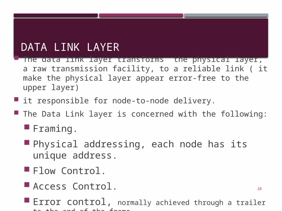
DATA LINK LAYER The data link layer transforms the physical layer, a raw
transmission facility, to a reliable link ( it make the physical layer appear error-free to the upper layer)
it responsible for node-to-node delivery.
The Data Link layer is concerned with the following:
Framing.
Physical addressing, each node has its unique address.
Flow Control.
Access Control.
Error control, normally achieved through a trailer to the end of the frame.
29
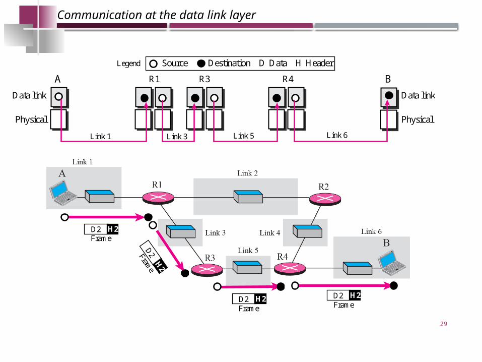
Communication at the data link layer
A
Physical Physical
Data linkData link
R1 R3 R4 B
Source Destination DataD HeaderHLegend
Link 1 Link 3 Link 5 Link 6
FrameD2 H2
Frame
D2H2
FrameD2 H2
FrameD2 H2

30
The unit of communication at the data link layer is a frame.
Note
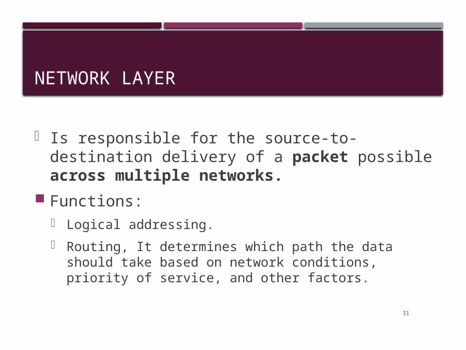
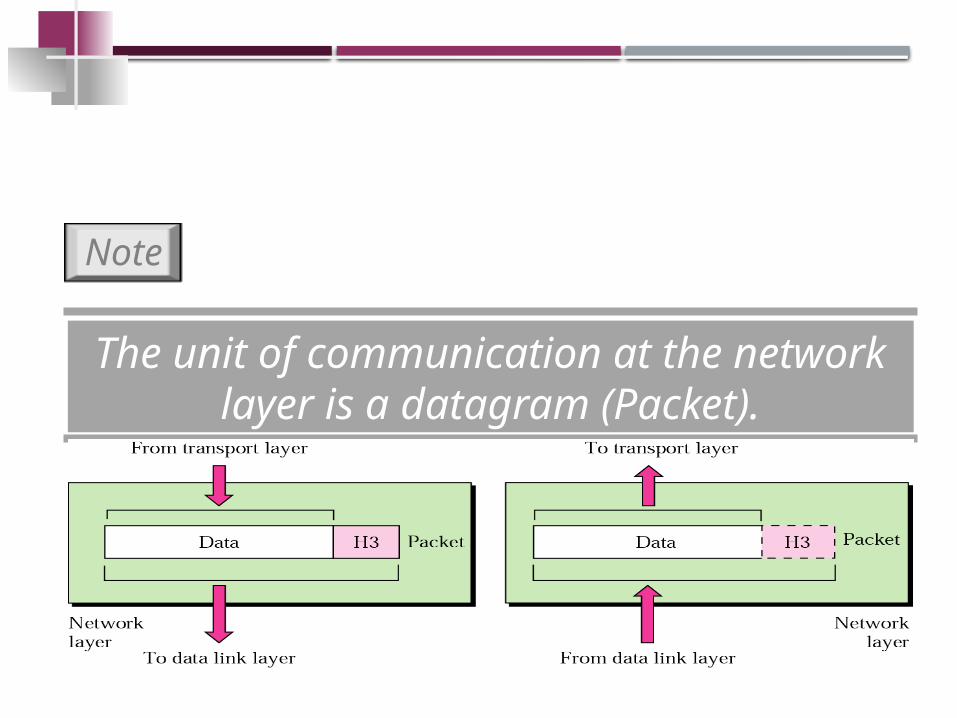
NETWORK LAYER
• Is responsible for the source-to-destination delivery of a packet possible across multiple networks.
Functions:• Logical addressing.
• Routing, It determines which path the data should take based on network conditions, priority of service, and other factors.
31

32
33
The unit of communication at the network layer is a datagram (Packet).
Note