CHAPTER 28fac.ksu.edu.sa/sites/default/files/ch28.pdf · Kalpakjian • Schmid Manufacturing...
18
Kalpakjian • Schmid Manufacturing Engineering and Technology © 2001 Prentice-Hall Page 28-1 CHAPTER 28 Solid-State Welding Processes
Transcript of CHAPTER 28fac.ksu.edu.sa/sites/default/files/ch28.pdf · Kalpakjian • Schmid Manufacturing...

Kalpakjian • SchmidManufacturing Engineering and Technology © 2001 Prentice-Hall Page 28-1
CHAPTER 28
Solid-State Welding Processes

Kalpakjian • SchmidManufacturing Engineering and Technology © 2001 Prentice-Hall Page 28-2
Roll Bonding
Figure 28.1 Schematic illustration ofthe roll bonding, or cladding, process

Kalpakjian • SchmidManufacturing Engineering and Technology © 2001 Prentice-Hall Page 28-3
Ultrasonic Welding
(a) (b)
Figure 28.2 (a) Components of an ultrasonic welding machine for lap welds. The lateralvibrations of the tool tip cause plastic deformation and bonding at the interface of theworkpieces. (b) Ultrasonic seam welding using a roller. (c) An ultrasonically welded part.
Kalpakjian • SchmidManufacturing Engineering and Technology © 2001 Prentice-Hall Page 28-4
Friction Welding
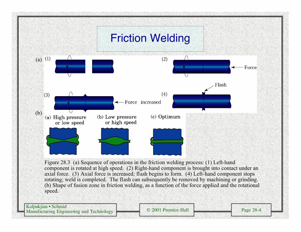
Figure 28.3 (a) Sequence of operations in the friction welding process: (1) Left-handcomponent is rotated at high speed. (2) Right-hand component is brought into contact under anaxial force. (3) Axial force is increased; flash begins to form. (4) Left-hand component stopsrotating; weld is completed. The flash can subsequently be removed by machining or grinding.(b) Shape of fusion zone in friction welding, as a function of the force applied and the rotationalspeed.
(a)
(b)
Kalpakjian • SchmidManufacturing Engineering and Technology © 2001 Prentice-Hall Page 28-5
Friction Stir Welding
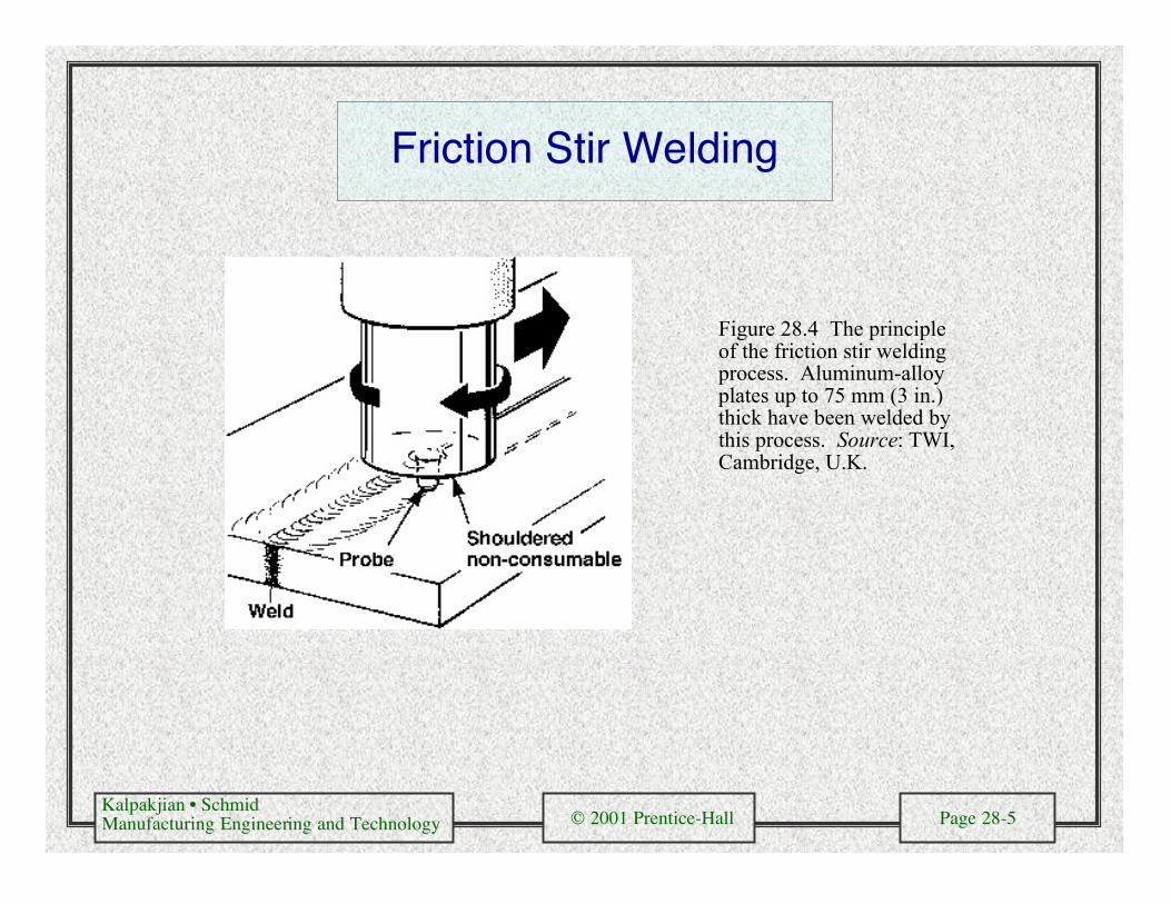
Figure 28.4 The principleof the friction stir weldingprocess. Aluminum-alloyplates up to 75 mm (3 in.)thick have been welded bythis process. Source: TWI,Cambridge, U.K.
Kalpakjian • SchmidManufacturing Engineering and Technology © 2001 Prentice-Hall Page 28-6
Resistance Spot Welding
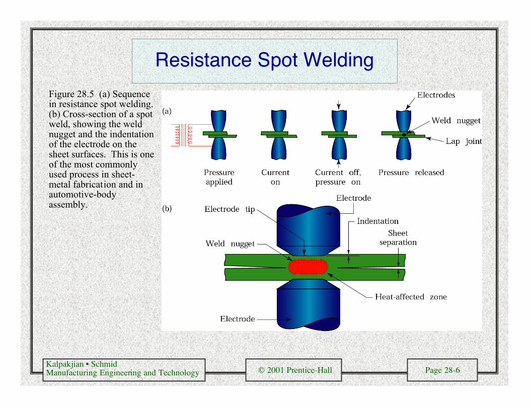
Figure 28.5 (a) Sequencein resistance spot welding.(b) Cross-section of a spotweld, showing the weldnugget and the indentationof the electrode on thesheet surfaces. This is oneof the most commonlyused process in sheet-metal fabrication and inautomotive-bodyassembly.
Kalpakjian • SchmidManufacturing Engineering and Technology © 2001 Prentice-Hall Page 28-7
WeldingMachineDesign
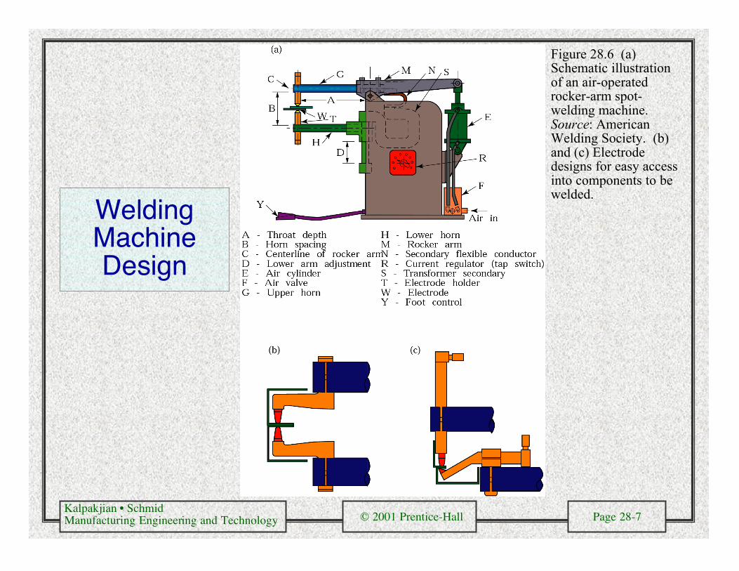
Figure 28.6 (a)Schematic illustrationof an air-operatedrocker-arm spot-welding machine.Source: AmericanWelding Society. (b)and (c) Electrodedesigns for easy accessinto components to bewelded.

Kalpakjian • SchmidManufacturing Engineering and Technology © 2001 Prentice-Hall Page 28-8
Examples of Spot Welding
(c)
(a) (b)
Figure 28.7 (a) and (b) Spot-welded cookware and muffler.(c) An automated spot-welding machine with aprogrammable robot; thewelding tip can move in threeprincipal directions. Sheets aslarge as 2.2 m X 0.55 m (88in. X 22 in.) can beaccommodated in thismachine. Source: Courtesy ofTaylor-Winfield Corporation.

Kalpakjian • SchmidManufacturing Engineering and Technology © 2001 Prentice-Hall Page 28-9
Spot Welding Example
Figure 28.8 Robots equipped with spot-welding guns and operated by computer controls, in amass-production line for automotive bodies. Source: Courtesy of Cincinnati Milacron, Inc.
Kalpakjian • SchmidManufacturing Engineering and Technology © 2001 Prentice-Hall Page 28-10
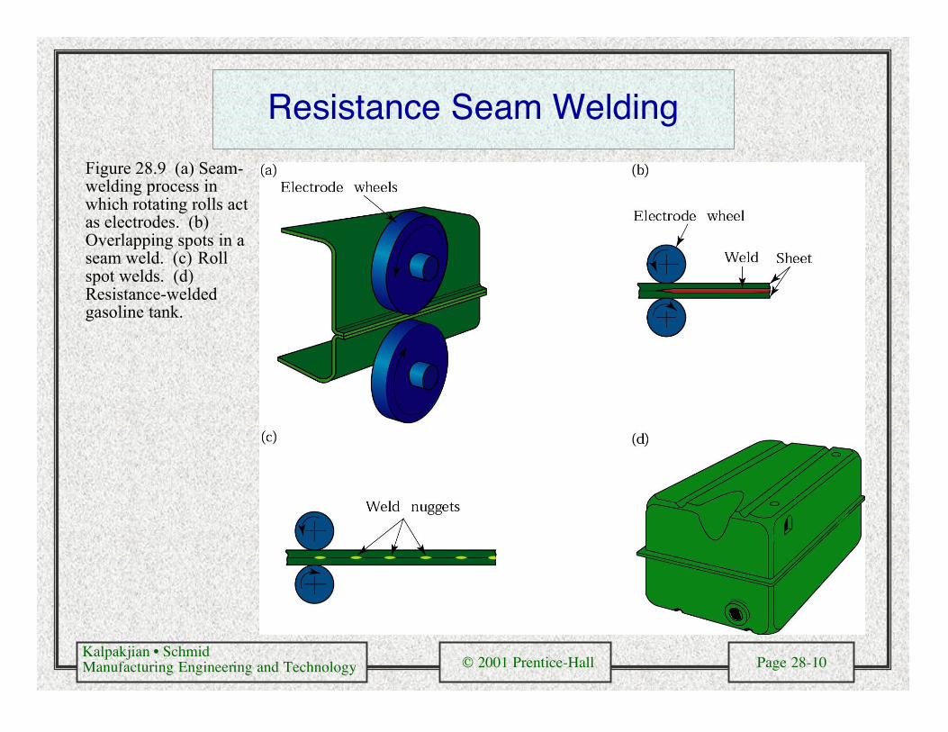
Resistance Seam Welding
Figure 28.9 (a) Seam-welding process inwhich rotating rolls actas electrodes. (b)Overlapping spots in aseam weld. (c) Rollspot welds. (d)Resistance-weldedgasoline tank.

Kalpakjian • SchmidManufacturing Engineering and Technology © 2001 Prentice-Hall Page 28-11
High-Frequency Butt Welding
Figure 28.10 Two methods of high-frequency butt welding of tubes.

Kalpakjian • SchmidManufacturing Engineering and Technology © 2001 Prentice-Hall Page 28-12
Resistance Projection Welding
Figure 28.11 (a) Schematic illustrationof resistance projection welding. (b) Awelded bracket. (c) and (d) Projectionwelding of nuts or threaded bosses andstuds. Source: American WeldingSociety. (e) Resistance-projection-welded grills.

Kalpakjian • SchmidManufacturing Engineering and Technology © 2001 Prentice-Hall Page 28-13
Flash Welding
Figure 28.12 (a) Flash-welding process for end-to-end welding of solid rods or tubular parts. (b)and (c) Typical parts made by flash welding. (d) Design Guidelines for flash welding.

Kalpakjian • SchmidManufacturing Engineering and Technology © 2001 Prentice-Hall Page 28-14
Stud Welding
Figure 28.13 The sequence of operations in stud welding, which is used for welding bars, threaded rods,and various fasteners onto metal plates.
Kalpakjian • SchmidManufacturing Engineering and Technology © 2001 Prentice-Hall Page 28-15
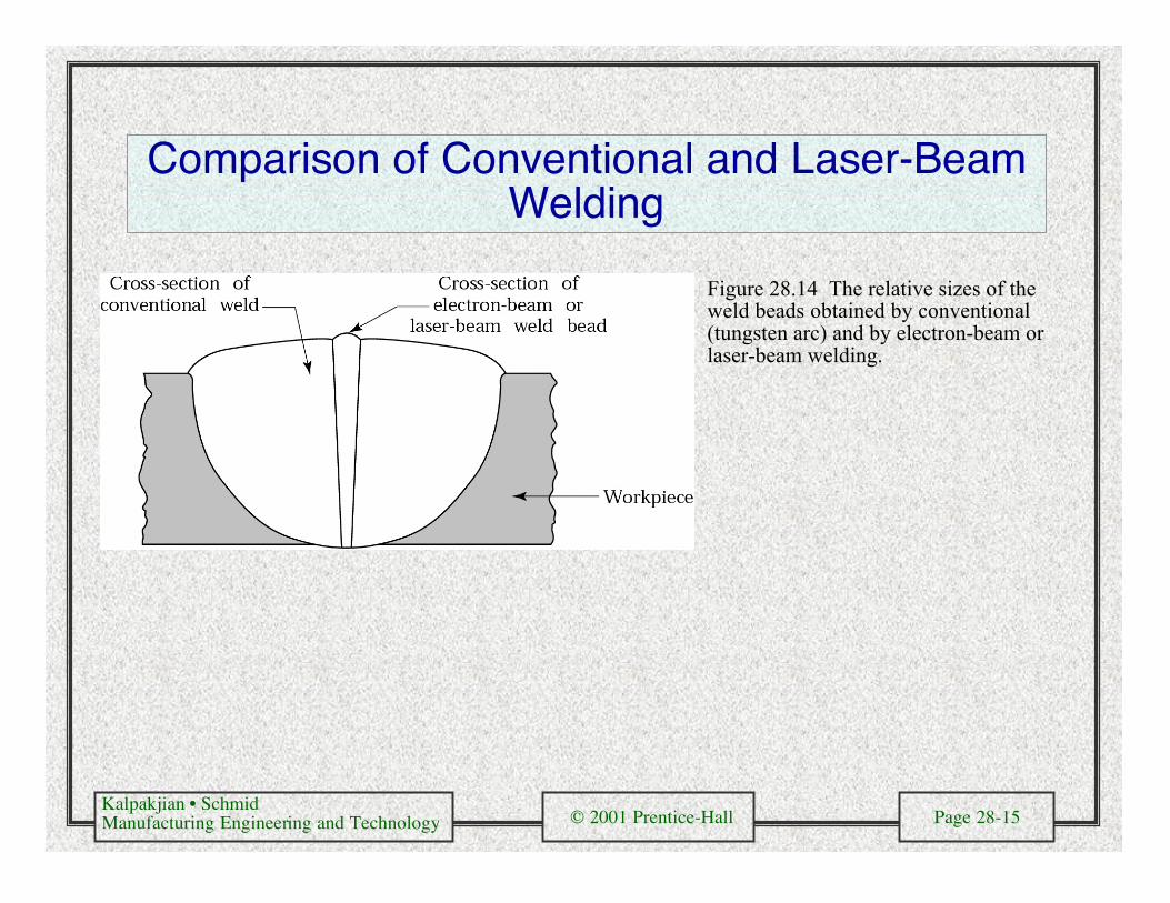
Comparison of Conventional and Laser-BeamWelding
Figure 28.14 The relative sizes of theweld beads obtained by conventional(tungsten arc) and by electron-beam orlaser-beam welding.

Kalpakjian • SchmidManufacturing Engineering and Technology © 2001 Prentice-Hall Page 28-16
Explosion Welding
Figure 28.15 Schematicillustration of the explosionwelding process: (a) constantinterface clearance gap and(b) angular interface clearancegap. (c) and (d) Cross-sections of explosion-weldedjoints. (c) titanium (top piece)on low-carbon steel (bottom).(d) Incoloy 800 (an iron-nickel-based alloy) on low-carbon steel. Source:Courtesy of E. I. Du Pont deNemours & Co.
(a) (b)
(c) (d)

Kalpakjian • SchmidManufacturing Engineering and Technology © 2001 Prentice-Hall Page 28-17
Diffusion Bonding Applications
Figure 28.16

Kalpakjian • SchmidManufacturing Engineering and Technology © 2001 Prentice-Hall Page 28-18
Diffusion Bonding/Superplastic Forming
Figure 28.17 The sequence of operations in thefabrication of various structures by diffusion bondingand then superplastic forming of (originally) flatsheets. Sources: (a) After D. Stephen and S.J.Swadling. (b) and (c) Rockwell International Corp.