Synchronous Sequential Circuits: Design Procedure and Examples

Chapter 26 Examples : DC Circuits
Key concepts:
• Internal resistance : battery consists of some idealized source of voltage (called the electro-motive force, or EMF, which uses the symbol ξ) and an effective internal resistance r. Theactual voltage produced by the battery (called the ‘terminal voltage’) will be Vba = ξ−Ir (whichtherefore varies as the current in the circuit changes).
• Resistors in series : Req = ΣRi
• Resistors in parallel : 1Req
= Σ 1Ri
• Kirchhoff’s Rules
– NODE or JUNCTION RULE: at any junction point, the sum of all currents entering thejunction must equal the sum of all the currents leaving the junction
– LOOP RULE: the sum of the changes in potential around any closed loop of a circuit mustbe zero. (Be careful with signs: the voltage will DROP across a resistor in the directionthe current is flowing, so if your ‘walk’ is in the same direction as the current, ∆V willbe negative, BUT if your walk takes you across the resistor in the opposite direction thecurrent is flowing, ∆V will be positive.)
• RC Circuits : simple circuit with a voltage source ξ, a resistor R and a capacitor C, all inseries. Charging: Q = Cξ(1 − e−t/τ ) VC = ξ(1 − e−t/τ ) I = ξ
Re−t/τ where τ = RC
• Discharging a capacitor through a resistance: Q = Qoe−t/τ I = Ioe
−t/τ VC = Q/C = Voe−t/τ
Older Stuff still used here
• Ohm’s Law: V = IR (voltage will drop in the direction current flows)
• Capacitor: Q = CV (positive charge on the higher voltage ‘side’)
• Power: P = V I = I2R = V 2/R (V here would be the voltage change just across this singleelement)

Wire Resistance (and why we usually ignore it)
Let’s compare a ‘pure’ circuit consisting of an idealizedbattery and a resistor, to two other cases. First, we’llinclude the internal resistance of the battery, then we’llalso include the resistance of the wires themselves.
Case 1 : Suppose we have an idealized 12 V battery connected across a 10 Ω resistor. How muchcurrent will flow and how much power is this circuit putting out (and where)? The voltage acrossthe resistor is the full 12 volts, so we can determine the current flowing through it: V = IR so here(12 volts) = (I)(10 Ω) or I = 1.2 amps. The resistor then is removing energy from the battery(turning it into heat) at a rate of P = I2R = (1.2)2(10) = 14.4 watts.
Case 2 : Assume the battery has an internal resistance of 0.5 Ω (essentially the figure on the right),but still has an EMF of 12 volts. How much current is flowing now? We have two resistors in seriesnow, which is an equivalent resistor of Req = ΣRi = (10 Ω) + (0.5 Ω) = 10.5 Ω. The current flowingnow will be I = V/R = (12 volts)/(10.5 Ω) = 1.143 amps (slightly less than the 1.2 A we had before).
How much power is being expended? P = I2R so the internal resistor is expending P = (1.143)2(0.5) =0.65 W and the 10 Ω load is expending P = (1.143)2(10) = 13.06 W , which is about 9 percent lessthan before. Accounting for the internal resistance of the battery affected the solution significantly.
Case 3 : Let’s add in the actual resistance of the wire itself now. In some earlier examples, wefound that the resistance of typical house and circuit wiring is very small - a fraction of an ohmover tens of meters. So let’s assume the wire here has a resistance of 0.01 Ω. Now in effect we havethree resistors in series: the internal resistance of the battery, the ‘real’ resistor at the bottom ofthe circuit, and the wire’s resistance. These are still in series, so the equivalent resistance of thiscircuit is Req = ΣRi = 10 + 0.5 + 0.01 = 10.51 Ω. The current flowing now will be I = V/R =(12 volts)/(10.51 Ω) = 1.142 amps (a further but very slight reduction).
Where is the power going now?
The power expended by the internal resistor will be P = I2R = (1.142)2(0.5) = 0.65 W . The 10 Ωresistor is expending power of P = I2R = (1.142)2(10) = 13.04 W (nearly the same as the previouscase where we accounted for the internal battery resistance but ignored the wire resistance), and thewire itself will be expending power at a rate of P = I2R = (1.142)2(0.01) = 0.013 W .
Summary : accounting for the internal resistance of the battery made reasonably significant changesto the current flowing and the power being expended by the load (which could be a light bulb, somemachine, a speaker, whatever...). Adding in the much smaller resistance of the wiring itself did furtherreduce the current and power but was a very small correction.
In typical circuit analysis, we just ignore the additional resistance that the wires them-selves are introducing.

Determining Battery Internal Resistance
The potential difference across the terminals of a battery is 8.4 V when there is a current of 1.50 Ain the battery from the negative to the positive terminal. When the current is 3.50 A in the reversedirection, the potential difference becomes 9.4 V . (a) What is the internal resistance of the battery?(b) What is the emf of the battery?
In the first case, we have the ‘normal’ flow of electricity through this battery. From the end of thechapter, for this case Vba = ξ − Ir. When we force the current to flow the ‘wrong’ way by attachingan external source of emf that is stronger than and reversed from the battery, we have Vba = −ξ − Irbut Vba = −Vba so −Vba = −ξ − Ir or Vba = ξ + Ir.
(Think of that as if we’re walking along this part of the circuit and applying Kirchhoff’s loop rules:what is the voltage change across each ‘element’ we run into.)
In the first case: Vba = ξ − Ir leads to 8.4 = ξ − 1.50rIn the second case, Vba = ξ + Ir leads to 9.4 = ξ + 3.5r.
This gives us two equations and two unknowns to solve. Rearranging each to solve for ξ, we have:ξ = 8.4 + 1.5r and ξ = 9.4 − 3.5r so 8.4 + 1.5r = 9.4 − 3.5r. Moving the r terms to the LHS and theconstants to the RHS: 1.5r + 3.5r = 9.4 − 8.4 or 5r = 1 from which r = 0.200 Ω.
Substituting this value for r into the first equation: ξ = 8.4 + 1.5r = 8.4 + 1.5(0.2) = 8.7 V .
By measuring the potential across and current through a battery running in these two situations, wecan determine its true emf ξ and internal resistance r.
(How can we make the current flow the ‘wrong way’ through a battery? By connecting it to a morepowerful voltage source that’s connected with a polarity that’s reversed.)
More Realistic Example
We don’t have to use a second battery and try to force the current to flow the wrong way through thefirst battery. We can determine the actual EMF and internal resistance of a battery by just connectingdifferent resistors to it and measuring the voltage across the battery (or the attached resistor).
When we connect a battery to a 2 Ω resistance, we measure that the voltage across the battery reads12.376 volts. If we use a 10 Ω resistor instead, we find the voltage reads 12.475 volts. What is theactual EMF ξ and internal resistance r of this battery?
As above, the voltage across the battery is Vba = ξ − Ir.
In the case of the 2 Ω resistor, the current flowing is Vba = IR so 12.376 = (I)(2) or I = 6.188 A.
Vba = ξ − Ir, so 12.376 = ξ − 6.188r .
With the 10 Ω resistor, Vba = IR so 12.475 = (I)(10) or I = 1.2475 A. Vba = ξ − Ir, so
12.475 = ξ − 1.2475r .
The two boxed equations give us 2 equations and 2 unknowns. Rearranging each to solve for ξ wehave ξ = 12.376 + 6.188r and ξ = 12.475 + 1.2475r so setting those equal to one another we find thatr = 0.02 Ω and using that value for r in either of the boxed equations yields ξ = 12.50 volts.

Resistor network (A)
For the circuit shown in the figure both meters are ideal-ized, the battery has no appreciable internal resistance,and the ammeter reads 2.00 A.(a) What does the voltmeter read?(b) What is the emf ξ of the battery?
We can solve this (mostly) without resorting to Kirchhoff by nibbling away at it, seeing what we caninfer from the lone bit of information we have (the current through the 25Ω resistor).
We only have a single source of voltage here, so the current will flow from the positive terminal ofthe battery, then counter-clockwise around the circuit, finally reentering the battery at the negativeterminal.
We only have a single source of emf here (the battery) so we can start off at least saying that somecurrent will be flowing along the ‘bottom’ of that circuit, heading to the right. This current then splitsinto three parts, flowing through the little network of resistors, then it recombines and passes throughthe 45Ω resistor, then the 35Ω resistor, and finally through the battery again.
Let’s start by looking at the cluster of four resistors in the top center of the figure:
Looking at the 25.0 Ω resistor, we know the current flowing through it is 2.00 A. Thus the voltagedrop across this resistor is V = IR = (25)(2) = 50.0 V olts.
This means that the voltage across the middle 15.0 Ω resistor is also 50 V , implying that I = V/R =(50)/(15) = 3.333 A is flowing through that resistor. Along the ‘bottom’ of this little resistor network,we have a 15.0 Ω and 10.0 Ω resistor in series, which means in effect we have a 25.0 Ω resistor there,which implies that the current flowing through these two must be I = V/R = (50)/(25) = 2.00 A.
Overall then, some current flows into this network of resistors and splits into three currents (whichwe now know), and then recombines into the current on the other side. The total current flowing into(and out of) this little cluster of resistors must be 2 + 3.333 + 2 = 7.333 A.
This 7.333 A of current now flows through the 45.0 Ω resistor, at which point a voltage drop ofV = IR = (7.333)(45) = 330.0 V olts occurs. (Answer to part (a).) It then continues on to the 35Ωresistor, at which point a voltage drop of V = IR = (7.333)(35) = 256.667 volts occurs.
Looking at the entire circuit now, let’s start in the lower right hand corner of the circuit and walkaround the circuit in a counter-clockwise loop, keeping track of the voltage changes we encounter.
The voltage drops by 50.0 V across the little cluster of 4 resistors (we already knew that from thearguments above), then it drops by 330.0 V across the 45 Ω resistor, then it drops 256.667 V acrossthe 35Ω resistor, and finally it gains ξ in the battery and we return to where we started. We’ve madea complete loop, so the sum of all these voltage changes must be zero: −50 − 330 − 256.667 + ξ = 0or ξ = 636.667 V (or rounded to three significant figures, 637 V ).

Resistor network (B) : Three resistors having re-
sistances of R1 = 1.60Ω, R2 = 2.40Ω and R3 = 4.80Ω areconnected in parallel to a 28.0 V battery that has neg-ligible internal resistance. Find (a) the equivalent resis-tance of the combination, (b) the current in each resistor,(c) the total current through the battery, (d) the voltageacross each resistor, (e) the power dissipated in each re-sistor. (f) Which resistor dissipates the most power: theone with the greatest resistance or the least resistance?
For resistors in parallel, 1Req
= 1R1
+ 1R2
+ 1R3
so 1Req
= 11.6Ω
+ 12.4Ω
+ 14.8Ω
. We luck out here and can get
an exact solution by putting everything over a common denominator: 1Req
= 34.8Ω
+ 24.8Ω
+ 14.8Ω
= 64.8Ω
.
So exactly: Req = 4.80Ω6
= 0.800Ω.
(Doing it the long way: 1Req
= 11.6Ω
+ 12.4Ω
+ 14.8Ω
= 0.6250Ω−1 + 0.4167Ω−1 + 0.2083Ω−1 = 1.250Ω−1 so
Req = 1/(1.250Ω−1) = 0.800Ω.)
The total current flowing will be V = IR or I = V/R = (28.0 volts)/(0.800 Ω) = 35 A, which willalso be the current flowing through the battery.
To find the current through each resistor individually: since these are connected in parallel, the voltagedrop across each of them is 28 V :I1 = V/R1 = (28V )/(1.60Ω) = 17.5000AI2 = V/R2 = (28V )/(2.40Ω) = 11.6667AI3 = V/R3 = (28V )/(4.80Ω) = 5.8333A.
(Note as a check that the sum of these three is equal to 35.0 A, which is the current we found to havebeen flowing through the ‘equivalent resistor’ we replaced these three with.)
The power dissipated in each resistor is given by various generic formulas relating the current, resis-tance, and voltage drop across the resistor: P = IV or P = I2R or P = V 2/R and the latter is themost convenient to use here since the voltage across each resistor is the identical 28.0 V :P1 = V 2/R1 = (28)2/(1.6) = 490.00 WP2 = V 2/R1 = (28)2/(2.4) = 326.67 WP3 = V 2/R1 = (28)2/(4.8) = 163.33 W .
The total power is the sum of these or 980 W . We can check this by looking at the circuit where we havereplaced all the resistors with the single equivalent resistor of 0.8Ω. In that case we have a 28V dropacross this resistor, meaning that the power being emitted by it is: P = V 2/Req = (28)2/(0.8) = 980W .
The smallest resistor was dissipating the largest fraction of the power. This happens in the case ofparallel resistors since the voltage drop across each of them is identical, so in P = V 2/R, the lowestresistor will account for the largest power use. (We will find the opposite to be true in the next examplewhere the resistors are in series instead of in parallel.)

Resistor network (C) : Three resistors having re-
sistances of R1 = 1.60Ω, R2 = 2.40Ω and R3 = 4.80Ω areconnected in series to a 28.0 V battery that has negligi-ble internal resistance. Find (a) the equivalent resistanceof the combination, (b) the current in each resistor, (c)the total current through the battery, (d) the voltageacross each resistor, (e) the power dissipated in each re-sistor. (f) Which resistor dissipates the most power: theone with the greatest resistance or the least resistance?
For resistors in series, Req = R1 +R2 +R3 so Req = 1.6Ω + 2.4Ω + 4.8Ω = 8.8Ω.
That means that we can immediately determine the amount of current flowing in this circuit: V = IRor I = V/R = (28V )/(8.8Ω) = 3.182A. (Which tells us how much current is flowing through thebattery at this point.)
This same current is flowing everywhere in the circuit (unlike the parallel case in the previous problem,there are no junctions anywhere here: everything is in a single continuous loop, so there is nowherefor the current to split up). In particular, we can look at each resistor individually. V = IR acrosseach resistor, so we can determine the voltage drop across each resistor:V1 = IR1 = (3.182)(1.60) = 5.09 voltsV2 = IR2 = (3.182)(2.40) = 7.64 voltsV3 = IR3 = (3.182)(4.80) = 15.27 volts.
The sum of these is 28.0 V as needed: taking a Kirchhoff loop through this circuit, the voltage goesup 28 V at the battery, then drops in total 28.0 V across the three resistors, making the sum of thevoltage changes zero around the complete loop, as needed.
The power emitted by each resistor can be found from P = V I = V 2/R = I2R. In this case, theP = I2R form is the easiest to apply since we know the current is the same in all three resistors:
P1 = I2R1 = (3.182)2(1.6) = 16.20 WP2 = I2R2 = (3.182)2(2.4) = 24.30 WP3 = I2R3 = (3.182)2(4.8) = 48.60 W .
The total power used by all three resistors is the sum of these or 89.1 W . We can check this by lookingat the power used by the equivalent resistor. In that case we have our 3.182 A current flowing througha single 8.8 Ω resistor, so P = I2R = (3.182)2(8.8) = 89.1 W . (For yet another check, we have this3.192 A current passing through the battery which increases the voltage of this current by 28 V so thepower being expended by the battery is P = V I = (28)(3.182) = 89.1 W as well.)
Note that unlike the case of the parallel resistors, when we connect them in series the biggest ‘user’of power is the largest resistor, instead of the smallest. This is because the CURRENT is the samethrough each resistor now, and P = I2R so the power scales up directly with the resistor. (Don’t readtoo much into these observations, since these cases were simple ones where ALL the resistors wereconnected either in parallel or series.)

Kirchhoff’s Rules : Simple Example 1
Suppose we connect a battery and threeresistors as shown in the figure. Determinethe current flowing through each resistorand the power each is emitting.
Note: we could do this problem without Kirchoff. The 20Ω and 30Ω resistors are basically in parallel,so they could be replaced with an equivalent resistance of 1
Req= 1
20+ 1
30or Req = 12Ω. This single
resistor is now in series with the 10Ω resistor, giving an equivalent resistance of 10+12 = 22Ω. In theend, we have a 12V battery connected to a 22Ω resistor, giving a current of V = IR or (12) = (I)(22)or I = 0.54546A flowing through the battery.
Let’s apply Kirchoff’s Laws to this circuit and see if we get the same result.
Process : mark all the nodes(places where 2 or more wires areconnected to each other), assigncurrents I in the segments betweennodes, identify loops.
Some current will be flowing in thewires in the left half of the circuit.That current splits at node A withsome of it flowing to the right andsome ‘down’ through the middle.Those two recombine at node B andcontinue to the negative terminal ofthe battery.
Node rule : at each node, the sum of the currents coming into a node is equal to the sum of thecurrents leaving that node (or the sum of the all the currents, accounting for their directions, will bezero). At node A: I1 = I2 +I3, and at node B: I2 +I3 = I1. Those are the same equation unfortunately,
so we really just get one unique equation from this step: I1 = I2 + I3 .

Loop rule : start anywhere and make a complete loop, noting the voltage changes as we cross eachelement in the circuit. The sum of the voltage changes around a complete loop must be zero. (Crossinga resistor, the voltage will drop in the direction the current is flowing, so take great care when ‘walking’around the loop: if we’re walking in the same direction as the current, that will be a voltage drop butif we’re walking opposite the current flow, the voltage will increase as we ‘step across’ the resistor.)
Loop 1 : clockwise path around the left square, starting in the lower left corner
• we pick up +12 V when we step across the battery
• V = IR and the voltage drops as current passes through a resistor; as we walk across the 10 Ωresistor, we’re moving in the direction the current is flowing, so across this element we will havea voltage change of −10I1
• continuing along the loop, current I2 is passing through the 20 Ω resistor and we’re walking inthe same direction the current is flowing, so we have a voltage change of −20I2 here. The loopnow continues along the bottom of the left box and reaches the point where we started, so we’redone.
• That’s a complete loop, so Σ∆V = 0 yields: +12 − 10I1 − 20I2 = 0
Loop 2 : clockwise path around the right square, starting in the lower right corner
• Walking along the ‘bottom’ of this square loop it’s just wire so we don’t have any voltage change.
• We now walk ‘up’ through R2, so there will be a voltage change of V = IR = (I2)(20) = 20I2
BUT we are walking through this resistor in the opposite direction the current is flowing.We drew the current ‘vectors’ as if I2 were flowing down so the voltage should drop in thatdirection. We’re moving across this this resistor in the opposite direction through, so from thebottom of the resistor to the top of that resistor, we should see the voltage rise by that amount.Here we pick up a voltage change of +20I2
• We now walk along the ‘top’ section of wire in this loop and nothing changes there.
• We now walk along the right side of the loop and we’re walking across R3 in the same directionas we drew the current I3 so the voltage here will drop, giving a voltage change from V = IR of−30I3 .
• That’s a complete loop, so Σ∆V = 0 yields: +20I2 − 30I3 = 0

We now have three equations and three unknowns:
• I1 = I2 + I3 (from the node rule),
• +12 − 10I1 − 20I2 = 0 (from the loop on the left)
• 20I2 − 30I3 = 0 (from the loop on the right)
There are many ways of solving these. The third equation basically tells us that I2 = 1.5I3 so let’s usethat to replace I2 in the other two equations:
The first equation becomes: I1 = (1.5I3) + I3 or just I1 = 2.5I3. (That’s convenient.)
The second equation becomes: 12 − 10I1 − 20(1.5I3) = 0 or 12 − 10I1 − 30I3 = 0
BUT we just found that I1 = 2.5I3 so we can rewrite that last equation as 12 − 10(2.5I3) − 30I3 = 0
or 12 − 25I3 − 30I3 = 0 or 12 = 55I3 or finally I3 = 12/55 = 0.21818 amp .
I1 = 2.5I3 = 2.5(0.21818) so I1 = 0.54546 amp (matching what we found earlier by not using Kirchoff)
and I2 = 1.5I3 = (1.5)(0.21818) or finally I2 = 0.32727 amp .
Power : We know all the currents flowing now, so let’s look at the power being dissipated by all theresistances in the circuit and the total power being drained from the battery.
• The 10 Ω resistor has I1 = 0.54546 amp flowing through it, representing a power dissipation ofP = I2R = (0.54546)2(10) ≈ 2.98 watts.
• The 20 Ω resistor has a current of I2 = 0.32727 amp flowing through it, so: P = I2R =(0.32727)2(20) ≈ 2.14 watt.
• The 30 Ω resistor has a current of I3 = 0.21818 amp flowing through it, so: P = I2R =(0.21818)2(30) ≈ 1.43 watt.
The total power output would be ΣP = 2.98 + 2.14 + 1.43 = 6.55 W . That’s 6.55 J/s and a typical12V car battery usually stores a few million joules of energy, so it would only take a few days to drainthis battery. (Presumably when the car is off, whatever is still pulling power from the battery is doingso at a much lower rate...)

Kirchhoff’s Rules : ‘Simple’ Example 2
Suppose we have two batteries and a single R = 10 Ω resistorthat we connect as shown in the figure. Each battery hasa small amount of internal resistance, denoted by the little0.1 Ω resistors next to them. Determine the currents ev-erywhere, how much power is being dissipated by the centerresistor R, and by the internal resistances of each battery,and determine the voltage Vba across resistor R. (Note thatthe positive terminals of the two batteries are connected to-gether.)
Process : mark all the nodes (places where 2 or more wiresare connected to each other), assign currents I in the seg-ments between nodes, identify loops.Some current will be flowing in the wires in the left half ofthe circuit; some other current will be flowing in the wires inthe right half, and some third current will be flowing throughthe resistor.Node rule: at each node, the sum of the currents cominginto a node is equal to the sum of the currents leaving thatnode (or the sum of the all the currents, accounting for theirdirections, will be zero). At node A: I1 + I2 = I3, and atnode B: I3 = I1 + I2. Those are the same equation unfor-tunately, so we really just get one unique equation from thisstep: I1 + I2 = I3 .
(Note: hard to read but the labelon the middle resistor is I3.)
Loop rule: start anywhere and make a complete loop, noting the voltage changes as we cross eachelement in the circuit. The sum of the voltage changes around a complete loop must be zero.
Loop 1 : clockwise path around the left square, starting in the lower left corner
• we pick up +12 V when we step across the battery
• V = IR and the voltage drops as current passes through a resistor; as we walk across the 0.1 Ωresistor, we’re moving in the direction the current is flowing, so across this element we will havea voltage change of −0.1I1
• continuing along the loop, current I3 is passing through the 10 Ω resistor and we’re walking inthe same direction the current is flowing, so we have a voltage change of −10I3 here.
• That’s a complete loop, so Σ∆V = 0 yields: +12 − 0.1I1 − 10I3 = 0
Loop 2 : counterclockwise path around the right square, starting in the lower right corner
• we pick up +9 V when we step across the battery
• V = IR and the voltage drops as current passes through a resistor; as we walk across the 0.1 Ωresistor, we’re moving in the direction the current is flowing, so across this element we will havea voltage change of −0.1I2

• continuing along the loop, current I3 is passing through the 10 Ω resistor and we’re walking inthe same direction the current is flowing, so we have a voltage change of −10I3 here.
• That’s a complete loop, so Σ∆V = 0 yields: +9 − 0.1I2 − 10I3 = 0
We now have three equations and three unknowns:
• I1 + I2 = I3 (from the node rule),
• +12 − 0.1I1 − 10I3 = 0 (from the loop on the left)
• +9 − 0.1I2 − 10I3 = 0 (from the loop on the right)
There are many ways of solving these. Here, the first equation tells us that I3 is equal to I1 + I2 so wecould make that substitution into the 2nd and 3rd equations, leaving us with two equations and twounknowns:
12 − 0.1I1 − 10(I1 + I2) = 0 or 10.1I1 + 10.0I2 = 129 − 0.1I2 − 10(I1 + I2) = 0 or 10I1 + 10.1I2 = 9
Rearranging the second equation to solve for I1 : I1 = (9 − 10.1I2)/10.0 = 0.9 − 1.01I2 which we cannow substitute into the first equation: 10.1(0.9 − 1.01I2) + 10I2 = 12 or 9.09 − 1.0201I2 + 10I2 = 12or combining terms: 0.201I2 = −2.91 and finally I2 = −14.48 amp.
We found that I1 = 0.9 − 1.01I2 = 0.9 − 1.01(−14.48) = +15.52 amp.
And finally I3 = I1 + I2 = (15.52) + (−14.48) = +1.04 amp.
Note the sign that came out for I2. That tells us that the current in that part of the circuit isactually flowing the other way, which means it’s going through the battery in the ‘wrong’ direction.Energy is being transferred from the 12V battery into the 9V battery, charging it (but not for long,as we’ll see).
Let’s look at the power being dissipated by all the resistances in the circuit.
The 10 Ω resistor has I3 = 1.04 amp flowing through it, representing a power dissipation of P = I2R =(1.04)2(10) ≈ 11 watts.
The 0.1 Ω internal resistance of the battery on the left has a current of I1 = 15.52 amp flowing throughit, so P = I2R = (15.52)2(0.1) ≈ 24 watt.
The 0.1 Ω internal resistance of the battery on the right has a current of I1 = −14.48 amp flowingthrough it, so P = I2R = (14.48)2(0.1) ≈ 21 watt.
The internal resistors are dumping quite a bit of heat into their respective batteries, which could causethem to dangerously heat up.
Final bit: what is the potential Vba across the resistor? V = IR and we found that I3 = 1.04 amp isflowing from A to B through the resistor, which had a resistance of 10Ω so V = (1.04)(10) = 10.4 volts.The voltage drops in the direction of current flow, so point A is at a higher potential than point B.Vba = Va − Vb = +10.4 volts.

Resistor network (D) - Kirchhoff’s Rules
In the circuit shown in the figure, find (a) the current in resistorR, (b) the resistance R, (c) the unknown emf ξ. (d) If thecircuit is broken at point x, what is the current in resistor R?(NOTE: this is the same circuit as in the previous example,with different numerical values, but here we already know someof the currents...)
Kirchhoff’s rules let us convert a circuitinto a set of linear equations that we cansolve. Anywhere multiple ‘wires’ connect(called a junction), the sum of all the cur-rents flowing in and out must be zero, andif we make a complete loop around anypart of the circuit, the sum of all the volt-age changes along that path must add tozero.The first step then is to mark all the junc-tions in the circuit. In this case, we onlyhave two: the spots on the left and rightwhere the three wires connect. Now weneed to label all the possible currents thatcould be flowing, remembering that thecurrent can’t change unless it comes to ajunction. Once we’ve labelled a current atsome point, we can follow that wire alongas it passes through resistors and batteriesand all along that segment of the circuitthe current will be the same value, and inthe same direction.
For this particular circuit, we were given that the current in the ‘bottom’ wire is 6A and is directedto the right, so note that I’ve labelled all the parts of the circuit where the current must have thissame value as I1, with arrows denoting the direction the current must be flowing at that point. Wewere also given that the current on the ‘middle’ part of this circuit was 4A to the left, so I’ve calledthis I2 and labelled other points along that same segment as such. Finally, there is some unknowncurrent flowing through the top part of this circuit, so I called this I3 and guessed that it might betravelling counterclockwise. If that 28V battery were the only source of emf in this circuit, the currentwould definitely be flowing in that direction but since we have multiple batteries, it’s possible that theunknown emf along the middle segment of the circuit might be overpowering the known battery andwho knows what direction the current might be flowing. It could flow through the known battery inthe wrong direction (in which case it is, in effect, charging up that battery).
(Continued...)

The important thing here is to come up with a minimum number of unknowns Ii and choose a directionfor each of them, then consistently USE this direction information in the next step. If it turns out youchose incorrectly, all that happens is you end up with a negative value for that current: it’s magnitudeis still correct, it’s just flowing the other way.
JUNCTIONS: at these points, the sum of all the currents must be zero, which is just saying in equationform that the charges don’t disappear or pile up. At the junction on the left side of the figure, we haveI1 flowing OUT, and I2 and I3 flowing IN, so in equation form we write this as: −I1 + I2 + I3 = 0.But we were given that I2 = 4 and I1 = 6 so: −6 + 4 + I3 = 0 or I3 = 2 and we now have all thecurrent values. (In typical Kirchhoff problems it isn’t this easy but for this case we were given enoughinformation to make this step easy.) Note that I3 came out to be positive, which means we guessedcorrectly about the it’s direction. If you had drawn I3 going in the other direction, you would havecome up with I3 = −2 which is fine, we just have to account for that in later steps.)
LOOPS: We still need to find the values for the unknown resistor R and the unknown emf ξ in thiscircuit. Let’s consider a loop where we walk in a counterclockwise direction entirely around theouter part of this circuit (shown as LOOP 1 at the bottom of the figure above). Starting at the lowerleft hand corner of the figure, we’ll walk in the direction chosen and account for all voltage changeswe encounter. The first thing we run into is a 3Ω resistor, through which a current of 6A is flowing,to the right: i.e. the same direction we’re walking. The voltage drops across a resistor in the directionthe current is flowing, so that means that at this point V DROPS by IR = (6)(3) = 18 volts. Our
voltage change at this point then is −18V . We now continue walking around the circuit and nothinghappens until we encounter the unknown resistor R, through which is flowing a current of I3. If wedidn’t know either of these quantities, the voltage change at this point would be −I3R. We knowthat I3 = 2A though, so the voltage change crossing this resistor will be −2R . Now we encountera battery. The voltage increases inside a battery when we’re moving from the ‘low side’ to the ‘highside’ of the battery (i.e. from the negative to the positive terminal), and we are moving through this
battery in exactly that direction, so here the voltage along our path changes by +28V . We continuearound this loop and encounter nothing else until we get back to our starting point. Accumulating allthe voltage changes then: −18 − 2R + 28 = 0 which we can solve to find 10 = 2R or R = 5Ω .
To find the unknown ξ, let’s use a counterclockwise path through the bottom half of this circuit(labelled LOOP 2). Starting again at the lower left hand corner of the circuit, we have a current ofI1 = 6A passing through a R = 3Ω resistor and we’re walking in the same direction as the voltagedrop occurs, so this results in a voltage change of −18V . We continue around this loop, turninginto the middle part of the circuit at the right junction. Now we encounter the 6Ω resistor, throughwhich a 4A current is flowing in the same direction we are ‘walking’, so at this point the voltagedrops V = IR = (4)(6) = 24V , which represents a voltage change of −24V . Now we encounter theunknown battery ξ and we’re walking through it in the direction that should produce an increase in thevoltage level, so the voltage change at this point on our path is +ξ . Putting these together, around
our entire walk we have: −18 − 24 + ξ = 0 or ξ = +42V , which also tells us that the polarity of thebattery is correctly labelled in the figure.
(Continued on next page.)
NOW WE ARE TOLD that we break the circuit alongthe middle wire, basically disconnecting the 42V batteryfrom the 6Ω resistor. This changes the circuit into theone shown in this figure. Because of the break, thereis NO current flowing through the middle battery or re-sistor. The current is now flowing just around the re-maining outer part of this circuit. Along this path, thereare no real junctions anywhere. The ‘old’ junctions arenow pointless, since the current ’flowing’ along those lit-tle fragments is zero now. Looking at the ‘junction’ onthe left side of the circuit, we have I coming in fromabove, and the same I continues down. This becomesa fairly trivial circuit now. We have a 28V battery inseries with a 5Ω and 3Ω resistor, giving an equivalent re-sistance of 8Ω. The current flowing in THIS circuit thenis I = V/R = (28)/(8) = 3.5A

Resistor network (E) - Kirchhoff’s Rules
In the circuit shown in the figure, both batteries have in-significant internal resistance and the idealized ammeterreads 1.50A in the direction shown. Find the emf ξ ofthe battery. Is the polarity shown in the figure correct?(Again, note that this is the same circuit as the previousexamples used but we know different information thistime.)
We start by marking the two junctions on the circuit, and then labelling the currents (with ‘guessed’directions).
We were given the current at one point, sowe’ll label that as I1. This current starts atthe lower junction, continues left throughthe ammeter, turns and heads through the75V battery, then turns and heads througha 12Ω resistor, at which point it reaches an-other junction. All along that left ‘half’of the circuit, the current has to havethe same value I1 and has to continue inthe same direction. Starting at the upperjunction, we’ll guess that I2 heads off tothe right, turns down through the battery(note it is passing through the battery inthe ‘wrong’ direction but that’s fine - we’lltake care of that with the proper sign whenwe start turning the circuit into equations).Then I2 passes through a 15Ω resistor andturns into the bottom junction. So nowwe’ve labelled all parts of the circuit whereI2 exists.
Finally we have the unknown current I3 passing from junction to junction through the 48Ω resistor.We’ll randomly guess that it is going in the direction shown. Again as in the previous problem, whatdirection you choose DOES NOT MATTER, just be consistent with it when you turn the circuit intoequations in the next steps.
JUNCTIONS: at the upper junction, we have I1 and I3 coming in, and I2 going out, so I1 +I3−I2 = 0.We do already know that I1 = 1.5A so let’s write this as 1.5+I3−I2 = 0. (The lower junction duplicatesthis information, so doesn’t tell us anything new.)
LOOPS: Let’s start by taking a loop around the left half of the circuit, labelled as ‘LOOP 1’ below thefigure. Choosing this loop was not arbitrary: as I looked at all the possible loops in this circuit, thisleft one involves things we already know plus only a single unknown variable: I3. That means thatthis loop will be enough to directly solve for this unknown. Other choices for loops would have 2 ormore unknowns. Still solvable, but I’d end up with a handful of linear equations that I’d need to tinkerwith, rather than this loop that directly gave a solution. Anyway, starting at the lower left corner

of the circuit, we gain 75V passing through the known battery. Next, we encounter the 12Ω resistor.The I1 = 1.5A current is flowing through this battery in the direction shown, which means the voltageshould DROP by V = IR = (1.5)(12) = 18V at this point, giving us a voltage change of −18V . Nowour Kirchhoff loop walks us from the upper junction to the lower junction. According to our choicesfor the directions of the various currents, we claimed that I3 was flowing UP here. That means thevoltage should drop by V = IR = (48)(I3) when I move across the resistor in the direction of thecurrent. But I’m not: my Kirchhoff path is taking me across this resistor in the ‘wrong’ direction,which means that according to my path, the voltage should RISE by 48I3 at this point. The pathnow continues around to reach where we started with no further resistors of batteries to consider. Ourcomplete equation accumulating all the voltage changes along this loop then is: +75 − 18 + 48I3 = 0or 48I3 = 18 − 75 = −57 or I3 = −57/48 or finally I3 = −1.1875A . (The negative sign means thecurrent is flowing in the opposite direction we thought. That’s fine. You could go back and switch thedirection of the I3 in the figure to make it positive in that direction (and also alter any other equations,like the JUNCTION ones, to account for this new direction), or you can just leave things as they areand account for the sign when determining voltage changes later...
From our junction equation, 1.5 + I3 − I2 = 0 or I2 = 1.5 + I3 and we know I3 = −1.1875A now, soI2 = 1.5 − 1.1875 or I2 = 0.3125A .
Finally, we can look at the right half of the circuit (shown as LOOP 2 in the figure) to find theunknown ξ. Using our original labels and directions, if we walk clockwise around this loop startingat the lower junction, we first pass through the 48Ω resistor in the same direction the current I3 waspresumed to be flowing, so we have a voltage change of −48I3 here. Next we go through the batteryin the wrong direction, giving us a voltage change of −ξ. Then we have current I2 passing throughthe 15Ω resistor and we’re walking in the direction for which the voltage should drop, so we have avoltage change here of −15I2. The sum of all these voltage changes then is: −48I3 − ξ − 15I2 = 0 soξ = −48I3 − 15I2 = −48(−1.1875) − 15(0.3125) = +57.0 − 4.6875 or finally ξ = +52.3125 . The signimplies that the polarity of the battery was labelled correctly. If we had gotten a negative value here,then the + sign on that battery would have had to have been on the other side.

Resistor network (F) : (Redoing an example I
made up on the fly for a lecture and didn’t get the cur-rents to add up properly...)In the circuit shown, assume we have an idealized 48 Vbattery that is connected to the resistor network shown.The three resistors in parallel all have the same resis-tance: R1 = R2 = R3 = 10Ω, and R4 = 40Ω.Determine the overall current flowing, the voltage dropfrom A to B, the voltage drop from B to C, the currentflowing through each resistor, and the power being emit-ted by each resistor.Assume the wires themselves have no resistance. (Theywill have some, but it will be tiny fractions of an Ohm,so won’t significantly affect the results.)
First, let’s compute the equivalent resistance here. We have three 10 ohm resistors in parallel, sothey add inversely: 1
Req= Σ 1
Riso here: 1
Req= 1
10+ 1
10+ 1
10= 3
10so Req = 10/3 = 3.3333..Ω.
We’ve replaced the three in parallel with this single 3.333..Ω resistor.
That leaves us with two resistors in series, which we can combine using: Req = ΣRi = 3.333..+ 40 =43.333..Ω.
Our circuit now consists of the 48 V voltage source flowing through this single equivalent resistance of43.333..Ω. We can find the current flowing then from V = IR so I = V/R = 48/43.3333.. = 1.1077 A.(I’m keeping lots of significant figures here to avoid the round-off problem I had in the lecture.)
That’s the amount of current that flows through the battery and runs along the wires into the resistornetwork, then out of it and back into the battery.
Expanding the resistors back out, how much does the voltage drop across resistor 4? V = IR soV = (1.1077...A)(40Ω) = 44.3077 volts. Walking completely around the circuit, we gain 48 voltsat the battery, lost some unknown voltage V across the network of three resistors, then lose 44.3077volts across the 40 ohm resistor, and then we’re back where we started so 48 − V − 44.3077 = 0 orV = 3.6923.. volts must be the voltage drop across the little 3-resistor network.
Focusing on that little sub-network, the voltage across each of those three resistors is 3.69 volts so wecan compute the current through each of them. V = IR again, so I1 = V/R1, I2 = V/R2, etc. Sinceall these resistors were the same value, I1 = I2 = I3 = (3.69 volts)/(10 Ω) = 0.36923.. amps.
The total current flowing through these three resistors will be 0.36923+0.36923+0.36923 = 1.1077 amps(identical to the 1.1077 amps flowing into and out of that little sub-network).
How much power is each resistor emitting?
We found that each of the little 10 Ω resistors had 0.36923.. A of current flowing through them, soP = I2R = (0.36923..)2(10) = 1.3633 W . We found that 1.1077 A was flowing through the 40Ωresistor, so it is emitting heat at rate of P = I2R = (1.1077..)2(40) = 49.08 W .
Combining all four resistors, they’re emitting a total of (1.3633)(3) + 49.08 = 53.2 W .

Looking back, at one point we had combined all the resistors into a single equivalent resistor of43.333..Ω, through which 1.1077 A of current was flowing, so that gives us a total power output ofP = I2R = (1.1077)2(43.333..) = 53.2 W also.
The battery is losing energy at that rate (which probably won’t last long...)
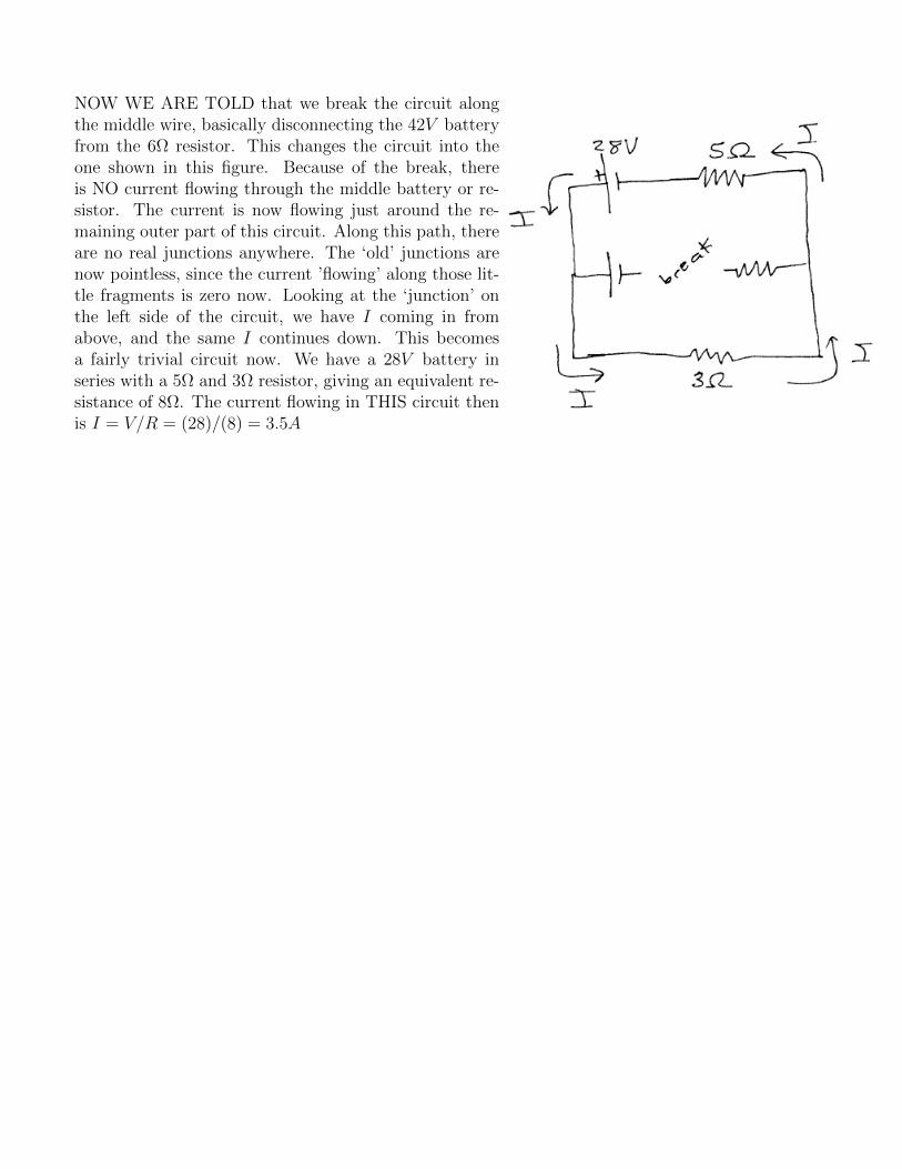
Jump-starting a car - Kirchhoff’s Rules
First, let’s look at the normal situation: the car batteryconnected in series with the starter motor. The batteryprovides some internal EMF ξ (volts) and also containsan effective internal resistance r. The current flows fromthe positive battery terminal and through the starter mo-tor, which has some resistance Rs. Let’s take a Kirchoff‘walk’ around this circuit, starting from the battery andwalking clockwise around the circuit.
We gain ∆V = ξ volts crossing over the battery. Then the current I passing through the internalbattery resistance r will represent a voltage drop of magnitude Ir in the direction the current is flowing.Our ‘walk’ is in the same direction the current is flowing, so we’ll encounter a ∆V = −Ir when westep over this resistor.
Finally, we encounter the starter motor and we’re walking in the same direction as the current isflowing, so we encounter a ∆V = −IRs there.
Looking at all the voltage changes around this closed loop (which must add to zero) then: Σ∆V =ξ − Ir − IRs = 0. Rearranging terms, we can write this as ξ = I(r +Rs) or I = ξ
r+Rs.
Good Battery : the starter motor has a resistance of Rs = 0.15 Ω and a good car battery wouldhave an EMF of ξ = 12.5 volts and an internal resistance of r = 0.02 Ω. In this case, the currentflowing through this circuit would be I = ξ
r+Rs= 12.5
0.02+0.15= 73.53 A.
The power that the starter motor will be using then is P = I2R = (73.53)2(0.15) = 811 watts.
Bad Battery : a bad battery will deliver a lower voltage (emf) and may have a higher internalresistance so here let’s assume ξ = 10.0 volts and r = 0.2 Ω. In this case, the current flowing throughthis circuit would be I = ξ
r+Rs= 10
0.1+0.15= 40.0 A.
The power that the starter motor will be using then is P = I2R = (40.0)2(0.15) = 240 watts.
Jump StartTo jump-start a ‘dead’ (or low) battery, we basically con-nect another battery in parallel with it: the positive ter-minal of the good battery being connected to the positiveterminal of the bad battery, and similarly the negativeterminal of the bood battery connected to the negativeterminal of the bad battery, as shown in the figure.
In the book version of this example, they also (realistically) add in some resistance in the jumpercables, but for this example let’s ignore that and use the ‘good’ and ‘bad’ battery EMF’s and internalresistances we used above.
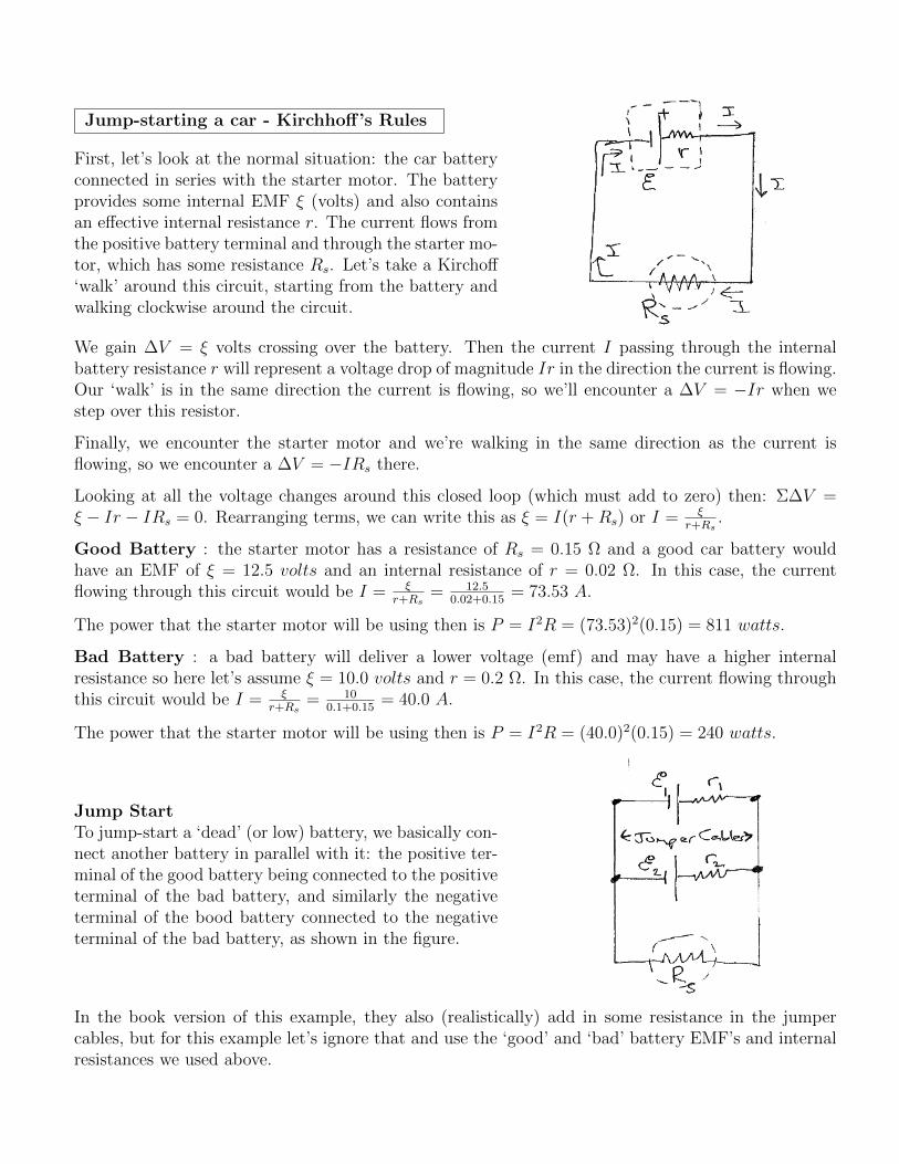
We have two nodes (junctions) here: places where two of more wires come together. Those representspots where currents can split up or combine. I labelled them A and B in the figure.
Normally, current flows out from the positive side of the battery, so we’ll add I1 and I2 currentsassociated with those points in the figure. From node to node, the current can’t change, so we musthave the same I1 current from node A, then heading ‘up’, then to the right (through the good batteryand it’s internal resistance, and then ‘down’ the right side until it hits node B.
Similarly, we have the same I2 current flowing from A to B through the bad battery and it’s internalresistance.
Finally, at the nodes (junctions), we have some other current flowing from B down through the startermotor and back up to A.
Node/Junction rule : ΣinI = ΣoutI
At node A then we have I3 = I1 + I2 and at node B we have I1 + I2 = I3. Those are actually the sameequation, we only get one unique equation: I1 + I2 = I3 .
Loop Rule for upper loop : let’s ‘walk’ around the closed loop that represents the upper half of thiscircuit. We’ll start at point A and walk in a clockwise look around this loop. What voltage changesdo we encounter?
• good battery: we’re walking from the low side to the high side of this battery, so ∆V = +12.5 v
• good battery’s internal resistor: we’re walking across this resistor in the same direction as (wethink) the current is flowing, so the voltage will DROP: ∆V = −I1r1 = −0.02I1.
• bad battery’s internal resistor: we’re walking across this resistor in the OPPOSITE DIRECTIONof the current there, which means we’ll actually pick up voltage in the direction we’re travelling:∆V = +I2r2 = +0.1I2
• bad battery’s emf: the voltage is higher on the positive side of the battery and here we’re walkingfrom the high to the low side, we our voltage change will be negative: ∆V = −10 volts.

Summing the voltage changes around that loop: +12.5 − 0.02I1 + 0.1I2 − 10 = 0 or combining andcollecting terms we can write this as 2.5 = 0.02I1 − 0.1I2
Loop Rule for lower loop : let’s ‘walk’ around the closed loop that represents the lower half of thiscircuit. We’ll start at point A and walk in a clockwise look around this loop. What voltage changesdo we encounter?
• bad battery: we’re walking from the low side to the high side of this battery, so ∆V = +10.0 v
• bad battery’s internal resistor: we’re walking across this resistor in the same direction as (wethink) the current is flowing, so the voltage will DROP: ∆V = −I2r2 = −0.10I2.
• starter motor: we’re walking across this resistor in the same direction as the current there, sothe voltage will drop: ∆V = −I3rs = −0.15I3
Summing the voltage changes around that loop: +10− 0.1I2 − 0.15I3 = 0 or combining and collectingterms we can write this as 10 = 0.1I2 + 0.15I3
Loop Rule for outer loop : let’s ‘walk’ around the closed loop that represents the outer perimeterof the circuit, labelled as loop 3 in the figure, starting and ending at node A.
• good battery: we’re walking across this battery from the low side to the high side, so pick up a∆V = 12.5 v at that point.
• now we step over the good battery’s internal resistance and we’re walking in the direction thecurrent is flowing so the voltage will drop there: ∆V = −0.02I1
• the next element we encounter is the starter motor and we’re walking across it in the directionthe current is allegedly flowing, so ∆V = −0.15I3.
Summing the voltage changes around that loop: +12.5 − 0.02I1 − 0.15I3 = 0 which we can write as12.5 = 0.02I1 + 0.15I3
Solution : We now have FOUR equations (in the boxes above) but only three unknowns. If we justwant to figure out how much power the starter motor has available to it now, we ultimately just needto know what I3 is, so let’s focus on equations that include that variable:
• I1 + I2 = I3 (from either of the node rules)
• 10 = 0.1I2 + 0.15I3 (from the lower loop)
• 12.5 = 0.02I1 + 0.15I3 (from the outer loop)
Let’s use the first equation to eliminate I1 in the third equation. We can re-write the first equation asI1 = I3 − I2 and substituting in that expression for I1 in the third equation:
12.5 = 0.02(I3 − I2) + 0.15I3 = 0 and after expanding this out and combining terms, we have
12.5 = 0.17I3 − 0.02I2

This equation plus the ‘lower loop’ equation now give us 2 equations with 2 unknowns (I2 and I3)a
Ultimately, we find that I3 = 72.5 A, I2 = −8.75 A and I1 = 81.25 A.
Note that I2 came out negative, which means that current is actually flowing in the opposite directionwe though it would: some of the current flowing from the good battery is actually flowing INTO thebad battery (effectively charging it).
Also note that the current ultimately making it to the starter motor was 72.5 A which is actually abit LESS than what the motor would be getting if connected solely to the good battery. The powerdelivered to the motor now is P = I2R = (72.5)2(0.15) = 788 W .
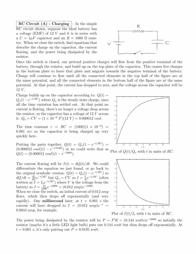
RC Circuit (A) - Charging : In the simple
RC circuit shown, suppose the ideal battery hasa voltage (EMF) of 12 V and it is in series witha C = 1µF capacitor and an R = 1000 Ω resis-tor. When we close the switch, find equations thatdescribe the charge on the capacitor, the currentflowing, and the power being dissipated by theresistor.
Once the switch is closed, our pretend positive charges will flow from the positive terminal of thebattery, through the resistor, and build up on the top plate of the capacitor. This causes free chargesin the bottom plate to leave that plate and migrate towards the negative terminal of the battery.Charge will continue to flow until all the connected elements in the top half of the figure are atthe same potential, and all the connected elements in the bottom half of the figure are at the samepotential. At that point, the current has dropped to zero, and the voltage across the capacitor will be12 V .
Charge builds up on the capacitor according to: Q(t) =Qo(1− e−t/RC) where Qo is the steady state charge, onceall the time variation has settled out. At that point nocurrent is flowing, there’s no longer a voltage drop acrossthe resistor, so the capacitor has a voltage of 12 V acrossit. Qo = CV = (1 × 10⁻⁶ F )(12 V ) = 0.000012 coul.
The time constant τ = RC = (1000)(1 × 10⁻⁶) =0.001 sec so the capacitor is being charged up veryquickly here.
Putting the parts together, Q(t) = Qo(1 − e−t/RC) =(0.000012 coul)(1 − e−t/0.001) or we could write that asQ(t) = (0.000012 coul)(1 − e−1000t).
Plot of Q(t)/Qo with t in units of RC.
The current flowing will be I(t) = dQ(t)/dt. We coulddifferentiate the equation we just found, or go back tothe original symbolic version: Q(t) = Qo(1 − e−t/RC) sodQ/dt = Qo
RCe−t/RC but Qo = CV so I = V
Re−t/RC (often
written as I = Ioe−t/RC) where V is the voltage from the
battery so I = 121000
e−1000t = (0.012 amp)e−1000t.When we close the switch, an initial current of 0.012 ampflows, which then drops off exponentially (and veryrapidly). One millisecond later, at t = 0.001 s thecurrent will have dropped to I = (0.012 amp)e−1 =0.0044 amp, for example.
Plot of I(t)/Io with t in units of RC.
The power being dissipated by the resistor will be P = I2R = (0.144 watts)e−2000t so initially theresistor (maybe it’s a little LED light bulb) puts out 0.144 watt but then drops off exponentially. Att = 0.001 s, it’s only putting out P = 0.0195 watt.

RC Circuit (B) - Discharging :
Suppose we have a C = 1µF capacitor that’s beencharged up with a 12 V battery as in the first ex-ample. Once the capacitor is fully charged, wedisconnect the battery and then connect the ca-pacitor to a lightbulb that has an internal resis-tance of R = 0.5 Ω. Determine the current flowand the power emitted by the bulb as a functionof time. How long does it take for the power out-put of the bulb to drop by half compared to itsinitial output?
For a capacitor discharging through a resistor, the charge on the capacitor behaves as Q = Qoe−t/RC
and differentiating, the current behaves as I = dQ/dt = − Qo
RCe−t/RC . That’s the rate at which charge
is leaving the capacitor, flowing from its positive plate around the circuit towards its negative plate.
The initial charge on the capacitor will be Qo = CV where V is the voltage (emf) of the battery itwas attached to. Making that substitution, we can write the current (magnitude) as I = CV
RCe−t/RC =
VRe−t/RC .
Here, the initial current Io = V/R = (12 volts)/(0.5 Ω) = 24 amps. The time constant here will beτ = RC = (0.5)(1 × 10⁻⁶) = 5 × 10⁻⁷ sec.
The current flow as a function of time then will be I(t) = (24 amp)e−t/(5×10−7) = (24 amp)e−2000000t.
The power flowing through the bulb will be P = I2R = (24)2(e−4000000t)(0.5) = (288 watts)e−4000000t.
At the instant the circuit is closed, the bulb starts emitting 288 watts (very bright). The brightnesshas dropped to half that when 144 = 288e−4000000t or 0.5 = e−4000000t. Taking the natural log of eachside: −0.693147.. = −4000000t or t = 1.73 × 10⁻⁷ sec or just 0.172 µsec.
This is essentially a flashbulb in a camera, which emits a very brief bright flash, then dies down toalmost nothing quickly. The very large initial power output (288 watts in this contrived example) ismore than a little battery can produce, but is no problem at all for even a small capacitor.
If we leave things symbolic, P = Poe−2t/RC so P = 1
2Po when 0.5 = e−2t/RC and taking the natural
log and rearranging a bit, we find that the ‘half-life’ of the power will be t1/2 = RC ln(2)2
≈ 0.346RC.With the values here, we found that the time constant τ = RC = 5 × 10⁻⁷ sec so the time for thepower output to drop by half would be (0.346)(5 × 10⁻⁷ s) = 0.173 µsec.
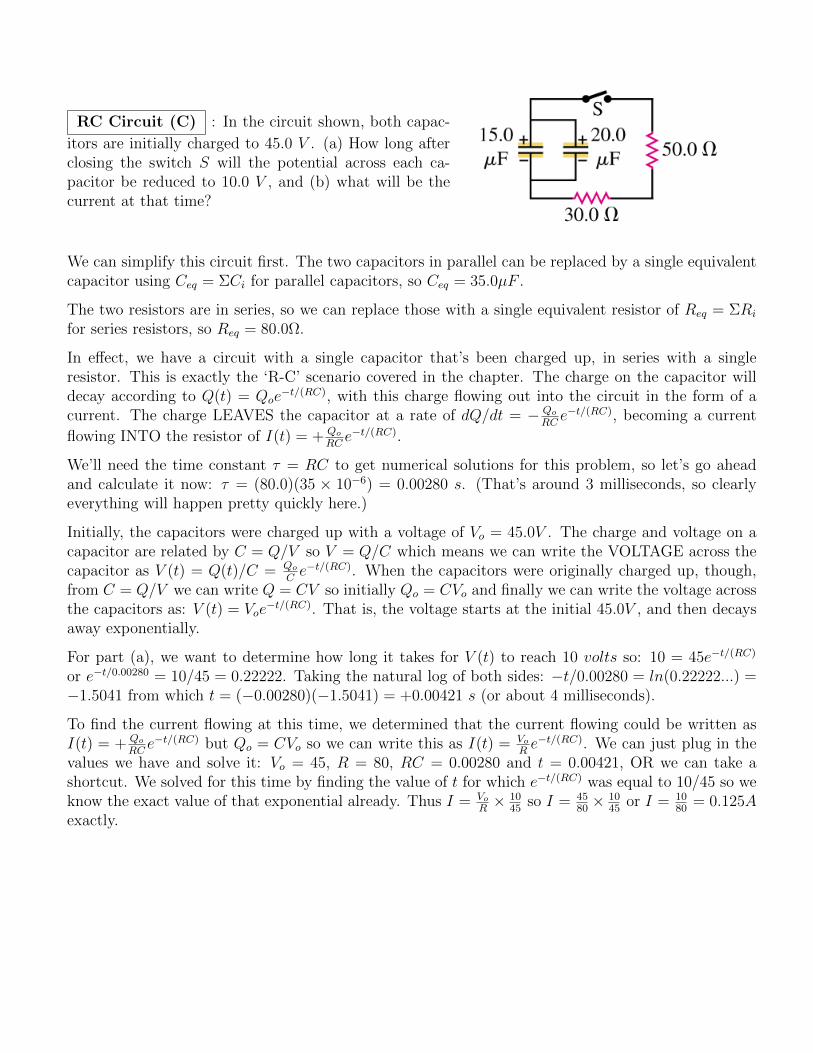
RC Circuit (C) : In the circuit shown, both capac-
itors are initially charged to 45.0 V . (a) How long afterclosing the switch S will the potential across each ca-pacitor be reduced to 10.0 V , and (b) what will be thecurrent at that time?
We can simplify this circuit first. The two capacitors in parallel can be replaced by a single equivalentcapacitor using Ceq = ΣCi for parallel capacitors, so Ceq = 35.0µF .
The two resistors are in series, so we can replace those with a single equivalent resistor of Req = ΣRi
for series resistors, so Req = 80.0Ω.
In effect, we have a circuit with a single capacitor that’s been charged up, in series with a singleresistor. This is exactly the ‘R-C’ scenario covered in the chapter. The charge on the capacitor willdecay according to Q(t) = Qoe
−t/(RC), with this charge flowing out into the circuit in the form of acurrent. The charge LEAVES the capacitor at a rate of dQ/dt = − Qo
RCe−t/(RC), becoming a current
flowing INTO the resistor of I(t) = + Qo
RCe−t/(RC).
We’ll need the time constant τ = RC to get numerical solutions for this problem, so let’s go aheadand calculate it now: τ = (80.0)(35 × 10−6) = 0.00280 s. (That’s around 3 milliseconds, so clearlyeverything will happen pretty quickly here.)
Initially, the capacitors were charged up with a voltage of Vo = 45.0V . The charge and voltage on acapacitor are related by C = Q/V so V = Q/C which means we can write the VOLTAGE across thecapacitor as V (t) = Q(t)/C = Qo
Ce−t/(RC). When the capacitors were originally charged up, though,
from C = Q/V we can write Q = CV so initially Qo = CVo and finally we can write the voltage acrossthe capacitors as: V (t) = Voe
−t/(RC). That is, the voltage starts at the initial 45.0V , and then decaysaway exponentially.
For part (a), we want to determine how long it takes for V (t) to reach 10 volts so: 10 = 45e−t/(RC)
or e−t/0.00280 = 10/45 = 0.22222. Taking the natural log of both sides: −t/0.00280 = ln(0.22222...) =−1.5041 from which t = (−0.00280)(−1.5041) = +0.00421 s (or about 4 milliseconds).
To find the current flowing at this time, we determined that the current flowing could be written asI(t) = + Qo
RCe−t/(RC) but Qo = CVo so we can write this as I(t) = Vo
Re−t/(RC). We can just plug in the
values we have and solve it: Vo = 45, R = 80, RC = 0.00280 and t = 0.00421, OR we can take ashortcut. We solved for this time by finding the value of t for which e−t/(RC) was equal to 10/45 so weknow the exact value of that exponential already. Thus I = Vo
R× 10
45so I = 45
80× 10
45or I = 10
80= 0.125A
exactly.