Chapter 23 Roads And Platforms - Indian...
55
Unified Standard Specifications For Works & Materials Chapter 23 : Roads and Platforms Page 792 : Chapter 23 Chapter 23 Roads And Platforms 23.1 General 23.1.1 Allowance for Settlement In the case of new roads and platforms, the sub-grade shall be shaped to suit the content of the finished surface and consolidated to a depth below the proposed finished level, equal to the combined depth of soling and wearing course after providing for an allowance for further settlement of sub-grade that may result during course of the work. Where the subsoil is of clay or other material, which is not easily drained, a top layer of ashes or sandy material to a depth of not less than 10 cm shall be provided. 23.1.2 Tools & Plant The Contractor shall provide all tools and plant, including rollers, water carts, mixers etc. at his own cost, unless otherwise specified. He shall also provide at his own expense such barriers, ropes, signals, night lanterns, watchmen, etc. as may be necessary for the protection of the public during construction or maintenance operations. 23.1.3 Safety of Traffic/Public No alteration or repairs to existing roads or platforms shall be undertaken without leaving free a portion of the width or providing a suitable diversion for the vehicular and other traffic which may be using it, so that its continued use is not denied to them. Further, no excavation, heaps of materials or other obstruction shall be left unprotected at night. It shall be the responsibility of the Contractor to ensure compliance of the above requirements. 23.1.4 Shoulders and Cess When carrying out repairs to roads, any deficiency in the shoulders (or earth berms) along both edges shall be made up properly, whether by earthwork or by dressing. These will be paid for separately only if the quantum of work involved is considered by the Engineer to the substantial. In the case of new roads, and platforms, the shoulders and cess shall invariably be cleared of all surplus materials, excess earth or other debris and dressed to the proper profiles, as directed, so as to ensure that there is no stagnation of water on or alongside the newly laid surface. No extra payment will be admissible for such clearance and dressing, except for any substantial quantity of earthwork involved. 23.1.5 Rolling (a)(a) Where the use of a power roller of a certain weight is specified, the Engineer may, at his discretion, permit the use of lighter roller or a hand roller, taking into account the magnitude of the work or other local circumstances, provided he is satisfied that the usefulness or the durability of the work is not affected to any appreciable extent. (b)(b) Along kerbs, manholes, etc. and any other place where proper consolidation by rolling is not practicable, alternative means such as steel rammers shall simultaneously by used to secure adequate consolidation. 23.1.6 Rates Unless otherwise specified, the rates shall be all-inclusive, covering the cost of all materials labour and equipment involved in the respective items of work. Earthwork in formation of new roads or platforms will, however, be paid for separately, as also any special work of improving the subgrade as per sub-para 23.1.5. 23.1.7 Scope Unless repugnant to the context, the specifications in this Chapter shall be applicable to both roads and platforms, and the term road used here-in-after shall also include platforms, where applicable. 23.2 Earthwork in Road Construction - Earthwork items are covered in EW chapter and relevant specifications may be followed. 23.3 PREPARATION OF SUB-GRADE 23.3.1 Sub-grade : The surface of the formation for width equal to that of the soling (or sub-base where provided) shall first be cut (where necessary) to a depth below the proposed finished level of the road, equal to the combined depth of sub-base (if provided), soling and wearing coat (due allowance being made for consolidation). It shall then be cleaned of all foreign substances.
-
Upload
vuongnguyet -
Category
Documents
-
view
225 -
download
4
Transcript of Chapter 23 Roads And Platforms - Indian...

Unified Standard Specifications For Works & Materials Chapter 23 : Roads and Platforms
Page 792 : Chapter 23
Chapter 23
Roads And Platforms
23.1 General
23.1.1 Allowance for Settlement
In the case of new roads and platforms, the sub-grade shall be shaped to suit the content of the finished surface and consolidated to a depth below the proposed finished level, equal to the combined depth of soling and wearing course after providing for an allowance for further settlement of sub-grade that may result during course of the work.
Where the subsoil is of clay or other material, which is not easily drained, a top layer of ashes or sandy material to a depth of not less than 10 cm shall be provided.
23.1.2 Tools & Plant
The Contractor shall provide all tools and plant, including rollers, water carts, mixers etc. at his own cost, unless otherwise specified. He shall also provide at his own expense such barriers, ropes, signals, night lanterns, watchmen, etc. as may be necessary for the protection of the public during construction or maintenance operations.
23.1.3 Safety of Traffic/Public
No alteration or repairs to existing roads or platforms shall be undertaken without leaving free a portion of the width or providing a suitable diversion for the vehicular and other traffic which may be using it, so that its continued use is not denied to them. Further, no excavation, heaps of materials or other obstruction shall be left unprotected at night. It shall be the responsibility of the Contractor to ensure compliance of the above requirements.
23.1.4 Shoulders and Cess
When carrying out repairs to roads, any deficiency in the shoulders (or earth berms) along both edges shall be made up properly, whether by earthwork or by dressing. These will be paid for separately only if the quantum of work involved is considered by the Engineer to the substantial.
In the case of new roads, and platforms, the shoulders and cess shall invariably be cleared of all surplus materials, excess earth or other debris and dressed to the proper profiles, as directed, so as to ensure that
there is no stagnation of water on or alongside the newly laid surface. No extra payment will be admissible for such clearance and dressing, except for any substantial quantity of earthwork involved.
23.1.5 Rolling
(a)(a) Where the use of a power roller of a certain weight is specified, the Engineer may, at his discretion, permit the use of lighter roller or a hand roller, taking into account the magnitude of the work or other local circumstances, provided he is satisfied that the usefulness or the durability of the work is not affected to any appreciable extent.
(b)(b) Along kerbs, manholes, etc. and any other place where proper consolidation by rolling is not practicable, alternative means such as steel rammers shall simultaneously by used to secure adequate consolidation.
23.1.6 Rates
Unless otherwise specified, the rates shall be all-inclusive, covering the cost of all materials labour and equipment involved in the respective items of work. Earthwork in formation of new roads or platforms will, however, be paid for separately, as also any special work of improving the subgrade as per sub-para 23.1.5.
23.1.7 Scope
Unless repugnant to the context, the specifications in this Chapter shall be applicable to both roads and platforms, and the term road used here-in-after shall also include platforms, where applicable.
23.2 Earthwork in Road Construction - Earthwork items are covered in EW chapter and relevant specifications may be followed.
23.3 PREPARATION OF SUB-GRADE
23.3.1 Sub-grade : The surface of the formation for width equal to that of the soling (or sub-base where provided) shall first be cut (where necessary) to a depth below the proposed finished level of the road, equal to the combined depth of sub-base (if provided), soling and wearing coat (due allowance being made for consolidation). It shall then be cleaned of all foreign substances.
Unified Standard Specifications For Works & Materials Chapter 23 : Roads and Platforms
Page 793 : Chapter 23
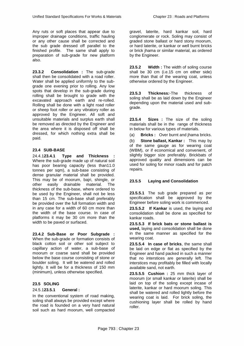
Any ruts or soft places that appear due to improper drainage conditions, traffic hauling or any other cause shall be corrected and the sub grade dressed off parallel to the finished profile. The same shall apply to preparation of sub-grade for new platform also.
23.3.2 Consolidation : The sub-grade shall then be consolidated with a road roller. Water shall be applied uniformly to the sub-grade one evening prior to rolling. Any low spots that develop in the sub-grade during rolling shall be brought to grade with the excavated approach earth and re-rolled. Rolling shall be done with a light road roller or sheep foot roller or any vibratory roller as approved by the Engineer. All soft and unsuitable materials and surplus earth shall be removed as directed by the Engineer and the area where it is disposed off shall be dressed, for which nothing extra shall be paid.
23.4 SUB-BASE
24.4.123.4.1 Type and Thickness : Where the sub-grade made up of natural soil has poor bearing capacity (less than11.0 tonnes per sqm), a sub-base consisting of dense granular material shall be provided. This may be of moorum, bajri, shingle, or other easily drainable material. The thickness of the sub-base, where ordered to be used by the Engineer, shall not be less than 15 cm. The sub-base shall preferably be provided over the full formation width and in any case for a width of 60 cm more than the width of the base course. In case of platforms it may be 30 cm more than the width to be paved or surfaced.
23.4.2 Sub-Base or Poor Subgrade : When the sub-grade or formation consists of black cotton soil or other soil subject to capillary action of water, a sub-base of moorum or coarse sand shall be provided below the base course consisting of stone or boulder soling. It will be watered and rolled lightly. It will be for a thickness of 150 mm (minimum), unless otherwise specified.
23.5 SOLING
24.5.123.5.1 General :
In the conventional system of road making, soling shall always be provided except where the road is founded on a very hard natural soil such as hard moorum, well compacted
gravel, laterite, hard kankar soil, hard conglomerate or rock. Soling may consist of graded stone ballast or hard stony moorum, or hard laterite, or kankar or well burnt bricks or brick jhama or similar material, as ordered by the Engineer.
23.5.2 Width : The width of soling course shall be 30 cm (i.e.15 cm on either side) more than that of the wearing coat, unless otherwise ordered by the Engineer.
23.5.3 Thickness:-The thickness of soling shall be as laid down by the Engineer depending upon the material used and sub-grade.
23.5.4 Sizes : The size of the soling materials shall be in the range of thickness in below for various types of materials.
(a) Bricks : Over burnt and jhama bricks.
(b) Stone ballast, Kankar : This may by of the same gauge as for wearing coat (WBM), or if economical and convenient, of slightly bigger size preferably. Brickbats of approved quality and dimensions can be used for soling for minor roads and for patch repairs.
23.5.5 Laying and Consolidation
23.5.5.1 The sub grade prepared as per specification shall be approved by the Engineer before soling work is commenced.
23.5.5.2 If Kankar is used, the laying and consolidation shall be done as specified for kankar roads.
23.5.5.3 If brick bats or stone ballast is used, laying and consolidation shall be done in the same manner as specified for the wearing coat.
23.5.5.4 In case of bricks, the same shall be laid on edge or flat as specified by the Engineer and hand packed in such a manner that no interstices are generally left. The interstices may profitably be filled with locally available sand, not earth.
23.5.5.5 Cushion : 25 mm thick layer of moorum (or small kankar or laterite) shall be laid on top of the soling except incase of laterite, kankar or hard moorum soling. This shall be watered and rolled lightly before the wearing coat is laid. For brick soling, the cushioning layer shall be rolled by hand roller.

Unified Standard Specifications For Works & Materials Chapter 23 : Roads and Platforms
Page 794 : Chapter 23
23.6 WATER BOUND MACADAM
23.6.1 Scope
23.6.1.1 This work shall consist of clean, crushed aggregates mechanically interlocked by rolling and bonding together with screening, binding material where necessary and water laid on a properly prepared sub grade/sub-base/base or existing pavement, as the case may be and finished in accordance with the requirements of these specifications and in close conformity with the lines, grades, cross-sections and thickness as per approved plans or as directed by the Engineer.
It is, however, not desirable to lay water bound macadam on an existing thin black topped surface without providing adequate drainage facility for water that would get accumulated at the interface of existing bituminous surface and water bound macadam.
23.6.1.2 General : The wearing surface either receives directly or through the finishing layer, the wheel loads and transmits them to the underlying layers. It must therefore :
(a) be sufficiently hard and tough to resist abrasion and the wearing action of traffic.
(The smoothness of the surface also affects abrasion, hence the surface shall also be made as smooth as possible, if it is the wearing course);
(b) be composed of tough stones which will resist the disruptive action of traffic with a minimum of maintenance and repair work;
(c) be capable of transmitting loads to the base under all weather conditions without undue deformation or creeping occurring. At the same time it shall have sufficient flexibility to adjust itself to the sub-grade without rupture;be non-slippery for traffic under all weather conditions
23.6.2 Thickness : Unless otherwise specified, the thickness of the wearing coat, if laid for the first time over soling course shall be 11.5 cm consolidated. For renewals it shall vary from 7.5 cm to 11.5 cm or as specified or as directed by Engineer.
23.6.3 Camber : The camber shall be 1 in 48 or as directed by the Engineer or otherwise specified.
23.6.4 Materials :
23.6.4.1 Physical requirements of coarse aggregate shall be as in Table 23.1 below :
TABLE 23.1 - PHYSICAL REQUIREMENTS OF COARSE AGGREGATES FOR WATER BOUND MACADAM FOR SUB-BASE/BASE COURSES
-------------------------------------------------------------------------------------------------------------------
Test Test Method Requirements
1. *Los Angeles Abrasion value (Part-4) IS: 2386 40 per cent (Max.)
Or
*Aggregate Impact value IS: 2386(Part-4) or 30 per cent (Max.)
IS: 5640**
2. Combined Flakiness and Elongation IS: 2386 (Part-1) 30 per cent (Max.)
Indices (Total) ***
------------------------------------------------------------------------------------------
Aggregate may satisfy requirement of either of the two tests.
** Aggregates like brick metal, kankar, laterite etc. which get softened
in presence of water shall be tested for impact value under wet conditions in accordance with IS: 5640.
*** The requirement of flakiness index and elongation index shall be
enforced only in the case of crushed broken stone
Para 23.6.7 also may be referred to for type of material and other quality requirements.
23.6.4.2 Overburnt (Jhama) brick aggregates : Jhama brick aggregates shall be made from over burnt bricks or brick bats and be free from dust and other objectionable and deleterious materials.
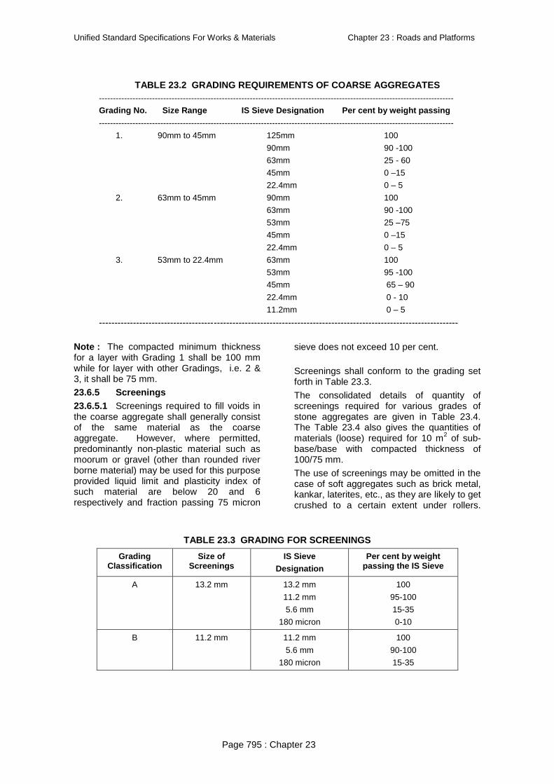
23.6.4.3 Grading requirement of coarse aggregates : The coarse aggregates shall conform to one of the Gradings given in Table 23.2 and as specified, provided, however, the use of Grading No.1 shall be restricted to sub-base courses only.
Unified Standard Specifications For Works & Materials Chapter 23 : Roads and Platforms
Page 795 : Chapter 23
TABLE 23.2 GRADING REQUIREMENTS OF COARSE AGGREGATES -------------------------------------------------------------------------------------------------------------------------------
Grading No. Size Range IS Sieve Designation Per cent by weight passing
-------------------------------------------------------------------------------------------------------------------------------
1. 90mm to 45mm 125mm 100
90mm 90 -100
63mm 25 - 60
45mm 0 –15
22.4mm 0 – 5
2. 63mm to 45mm 90mm 100
63mm 90 -100
53mm 25 –75
45mm 0 –15
22.4mm 0 – 5
3. 53mm to 22.4mm 63mm 100
53mm 95 -100
45mm 65 – 90
22.4mm 0 - 10
11.2mm 0 – 5
--------------------------------------------------------------------------------------------------------------------
Note : The compacted minimum thickness for a layer with Grading 1 shall be 100 mm while for layer with other Gradings, i.e. 2 & 3, it shall be 75 mm.
23.6.5 Screenings
23.6.5.1 Screenings required to fill voids in the coarse aggregate shall generally consist of the same material as the coarse aggregate. However, where permitted, predominantly non-plastic material such as moorum or gravel (other than rounded river borne material) may be used for this purpose provided liquid limit and plasticity index of such material are below 20 and 6 respectively and fraction passing 75 micron
sieve does not exceed 10 per cent.
Screenings shall conform to the grading set forth in Table 23.3.
The consolidated details of quantity of screenings required for various grades of stone aggregates are given in Table 23.4. The Table 23.4 also gives the quantities of materials (loose) required for 10 m2 of sub-base/base with compacted thickness of 100/75 mm.
The use of screenings may be omitted in the case of soft aggregates such as brick metal, kankar, laterites, etc., as they are likely to get crushed to a certain extent under rollers.
TABLE 23.3 GRADING FOR SCREENINGS
Grading Classification
Size of Screenings
IS Sieve
Designation
Per cent by weight passing the IS Sieve
A
13.2 mm
13.2 mm
11.2 mm
5.6 mm
180 micron
100
95-100
15-35
0-10
B
11.2 mm 11.2 mm
5.6 mm
180 micron
100
90-100
15-35
test

Unified Standard Specifications For Works & Materials Chapter 23 : Roads and Platforms
Page 796 : Chapter 23
TABLE 23.4 APPROXIMATE QUANTITIES OF COARSE AGGREGATES AND SCREEINGS REQUIRED FOR 100/75 MM COMPACTED THICKNESS OF WATER BOUND MACADAM
(WBM) SUB-BASE/ BASE COURSE FOR 10M2 AREA
Classific-ation
Size Range
Com-pacted
thickness
Loose Qty.
Screenings
Stone Screening Crushable Type such as Moorum or Gravel
Grading Classificatio
n & Size
For WBM Sub-base/base
course (Loose quantity)
Grading Classification & Size
Loose Qty.
Grading-1 90mm to 45mm
100 mm 1.21 to 1.43 m3
Type A 13.2 mm
0.27 to 0.30 m3 Not uniform
0.30 to 0.32m3
Grading-2 63mm to 45mm
75 mm 0.91 to 1.07m3
Type A 13.2 mm
0.12 to 0.15 m3 - do - 0.22 to 0.23 m3
- do - - do - - do - - do- Type B 11.2 mm
0.20 to 0.22 m3 - do - - do -
Grading-3 53mm to 22.4 mm
75 mm - do- - do - 0.18 to 0.21 m3 - do - - do -
Hard kankar nodules 6 mm to 12 mm size are more suitable for this purpose than screenings. In addition to retaining the stones in position, the kankar improves the cementing value and secures a smooth riding surface by resisting the tendency of the wearing coat to unravel.
The amount of screening or kankar nodules required depends on the degree of interlocking and compaction achieved during rolling and this depends largely on the quality of the stone and the efficiency of the rolling operation. With well-compacted stones, 9.5 to 13.5 cum will be sufficient for 1000 sqm of road surface.
23.6.5.2 Screenings : Screenings are the smaller size stones (6-12 mm gauge) of the same type as used for the wearing coat. These are used after full compaction of the loose stone is effected to keep the surface stone in inter- locked position.
23.6.5.3 Where soft stone such as laterite, kankar, etc., is used for the wearing coat, no screenings are required.
24.6.5.4 All screenings shall be clean, free from clay and organic matter, and shall be of the same specifications as the metal of the wearing coat except for the maximum size.
23.6.5.5 If screenings of ordinary stone or kankar are not available, laterite or hard moorum may be used in the same way.
23.6.6 Binding material : Binding material to be used for water bound macadam as a filler material meant for preventing ravelling, shall comprise of a suitable material approved by the Engineer having a Plasticity Index (PI) value of less
than 6 as determined in accordance with IS: 2720 (Part-5).
The quantity of binding material where it is to be used, will depend on the type of screenings, Generally, the quantity required for 75 mm compacted thickness of water bound macadam will be 0.06-0.09 m3 /10 m2
and 0.08-0.10 m3/10 m2 for 100 mm compacted thickness.
The above mentioned quantities should be taken as a guide only, for estimation of quantities for construction etc.
Application of binding materials may not be necessary when the screenings used are of crushable type such as moorum or gravel.
23.6.7 Stone Meal
23.6.7.1 Collection of stone metal : The stone metal shall be stacked in convenient units clear of the roadway, either on the berm or on level platforms provided for the purpose. No metal in excess to that required for the work shall be stacked at site and all excess quantity shall be removed rom the site of work before stack measurements are recorded. The height of a stack shall not be less than 60 cm. The quantity of material required for a particular finished thickness shall make due allowance for the reduction in thickness during consolidation. For payment, the quantity measured in stacks shall be reduced by 15% to allow for looseness and compaction.
23.6.7.2 Choice of Coarse aggregates : Coarse aggregates shall be either crushed or broken stone, crushed slag, over burnt (Jhama) brick aggregates or any other naturally occurring aggregates such as

Unified Standard Specifications For Works & Materials Chapter 23 : Roads and Platforms
Page 797 : Chapter 23
kankar and laterite of suitable quality. Materials other than crushed or broken stone shall be used in sub-base courses only. If crushed gravel/shingle is used, not less than 90 per cent by weight of the gravel/shingle pieces retained on 4.75 mm sieve shall have at least two fractured faces. The type and size range of aggregate shall be specified in the Contract or shall be as specified by the Engineer. It the water absorption value of the coarse aggregate is greater than 2 per cent, the soundness test shall be carried out on the material delivered to site as per IS: 2386 (Part 5).
23.6.7.3 Crushed or broken stone : The crushed or broken stone shall be hard, durable and free from excess flat, elongated, soft and disintegrated particles, dirt and other deleterious material.
23.6.8 Construction
23.6.8.1 Preparation of base : The surface of the subgrade/sub -base/base to receive the water bound macadam course shall be prepared to the specified lines and cross fall (camber) and made free of dust and other extraneous material. Any ruts or soft yielding places shall be corrected in an approved manner and rolled until firm surface is obtained, if necessary by sprinkling water. Any sub-base/base/surface irregularities, where predominant, shall be made good by providing appropriate type of profile corrective course (leveling course).
As far as possible, laying water bound macadam course over an existing thick bituminous layer may be avoided since it will cause problems of internal drainage of the pavement at the interface of two courses. It is desirable to completely pick out the existing thin bituminous wearing course where water bound macadam is proposed to be laid over it. However, where the intensity of rain is low and the interface drainage facility is efficient, water bound macadam can be laid over the existing thin bituminous surface by cutting 50 mm x 50 mm furrows at an angle of 45 degrees to the centre line of the pavement at one metre intervals in the existing road. The directions and depth of furrows shall be such that they provide adequate bondage and also serve to drain water to the existing granular base course beneath the existing thin bituminous surface.
23.6.8.2 Inverted Choke : If water bound macadam is to be laid directly over the subgrade, without any other intervening pavement course, a 25mm course of screenings (Grading B) or coarse sand shall be spread on the prepared subgrade before
application of the aggregates is taken up. In case of a fine sand or silty or clayey subgrade, it is advisable to lay 100 mm insulating layer of screening or coarse sand on top of fine grained soil, the gradation of which will depend upon whether it is intended to act as a drainage layer as well. As a preferred alternative to inverted choke, appropriate geosynthetics performing functions of separation and drainage may be used over the prepared subgrade as directed by the Engineer.
23.6.8.3 Spreading coarse aggregates : The coarse aggregates shall be spread uniformly and evenly upon the prepared subgrade/sub-base/base to proper profile by using templates placed across the road about 6 m apart, in such quantities that the thickness of each compacted layer is not more than 100 mm for Grading 1 and 75 mm for Grading 2 and 3. In larger works and wherever possible, approved mechanical devices such as aggregates spreader shall be used to spread the aggregates uniformly so as to minimize the need for manual rectification afterwards. Aggregates placed at locations which are inaccessible to the spreading equipment, may be spread in one or more layers by any approved means so as to achieve the specified results.
The spreading shall be done from stockpiles along the side of the roadway or directly from vehicles. No segregation of large or fine aggregates shall be allowed and the coarse aggregate as spread shall be of uniform gradation with no pockets of fine material.
The surface of the aggregates spread shall be carefully checked with templates and all high or low spots remedied by removing or adding aggregates as may be required. The surface shall be checked frequently with a straight edge / template while spreading and rolling so as to ensure a finished surface as per approved drawings.
The coarse aggregates shall not normally be spread more than 3 days in advance of the subsequent construction operations.
23.6.8.4 Rolling : Immediately following the spreading of the coarse aggregate, rolling shall be started with three wheeled power rollers of 80 to 100 kN capacity or tandem or vibratory rollers of 80 to 100 kN static weight. The type of roller to be used shall be approved by the Engineer based on trial run.
Except on super elevated portions where the rolling shall proceed from inner edge to the outer, rolling shall begin from the edges gradually progressing towards the centre. First the edge/edges shall be compacted

Unified Standard Specifications For Works & Materials Chapter 23 : Roads and Platforms
Page 798 : Chapter 23
with roller running forward and backward. The roller shall then move inward parallel to the centre line of the road, in successive passes uniformly lapping preceding tracks by at least one half width.
Rolling shall be discontinued when the aggregates are partially compacted with sufficient void space in them to permit application of screenings. However, where screenings are not to be applied, as in the case of crushed aggregates like brick metal, laterite and kankar, compaction shall be continued until the aggregates are thoroughly keyed. During rolling, slight sprinkling of water may be done, if necessary. Rolling shall not be one when the sub-grade is soft or yielding or when it causes a wave-like motion in the sub-grade or sub-base course.
The rolled surface shall be checked transversely and longitudinally with templates and any irregularities corrected by loosening the surface, adding or removing necessary amount of aggregates and re-rolling until the entire surface conforms to desired cross fall (camber) and grade. In no case shall the use of screenings be permitted to make up depressions
Material which gets crushed excessively during compaction or becomes segregated shall be removed and replaced with suitable aggregates.
It shall be ensured that shoulders are built up simultaneously along with water bound macadam courses.
23.6.8.5 Test for Dry rolling for interlocking and compaction : The metal shall be dry rolled until compaction is completed as judged by the following tests :
(i) No lines of the roller are left on the surface.
(i) A loaded cart leaves no indentation when passing over the rolled surface.
(ii) A piece of 25 mm gauge metal placed on the surface gets crushed under the roller without being driven in. The surface shall then be checked for camber and any inequalities in the surface corrected.
23.6.9 Application of screenings : After the coarse aggregate has been rolled, screenings to completely fill the interstices shall be applied gradually over the surface. These shall not be damp or wet at the time of application. Dry rolling shall be done while the screenings are being spread so that vibrations of the roller cause them to settle into the voids of the coarse aggregate. The screenings shall not be dumped in piles but
be spread uniformly in successive thin layers either by the spreading motions of hand shovels of by mechanical spreaders, or directly from tipper with suitable grit spreading arrangement. Tipper operating for spreading the screenings shall be so driven as not to disturb the coarse aggregate.
The screenings shall be applied at a slow and uniform rate (in threeor more applications) so as to ensure filling of all voids. This shall be accompanied by dry rolling and brooming with mechanical brooms, hand-brooms or both. In no case shall the screenings be applied so fast and thick as to form cakes or ridges on the surface in such a manner as would prevent filling of voids or prevent the direct bearing of the roller on the coarse aggregate. These operations shall continue until no more screenings can be forced into the voids of the coarse aggregate.
The spreading, rolling, and brooming of screenings shall be carried out in only such lengths of the road which can be completed within one day‘s operation.
23.6.10 Wet rolling and spreading of binding material : The surface shall then be copiously watered and rolled. After a few rollings, binding material like moorum or prepared earth shall be spread evenly to a thickness of 6 mm to 12 mm, copiously watered and rolled until a slurry of binder and water begins to flow ahead of the roller. The slurry shall be swept in with hand brooms so as to fill the voids properly and the surface rolled again, water being applied to the wheels in order to wash down the binder that may be sticking to them. The slurry shall be swept up from the haunches to the crown and no part of the slurry shall be allowed to flow off the road surface as this will result in the loss of soil fines, which impart binding properties to the material. The spreading of binder, sprinkling of water, sweeping with brooms and rolling shall continue until the slurry is formed after filling of voids, forms a wave before the wheels of the moving roller. The rolling at all times shall begin at the sides and progress towards the centre thoroughly covering the entire surface with the rear wheels till a hard smooth solid paving is produced.
23.6.11 General precautions during consolidation : Only such lengths shall be taken for consolidation as can be completed in a day. The scarifying and preparing of the surface may, however, be pushed on well in advance by two day‘s length and metal spreading by one day‘s length.

Unified Standard Specifications For Works & Materials Chapter 23 : Roads and Platforms
Page 799 : Chapter 23
23.6.11.1 When the work is done over only half the width of the road at a time, the rolling shall be done over not more than half the width. The marginal 40 cm width in the middle should not be rolled nor should be treated with screenings until the second half width is taken up.
23.6.11.2 No sudden steps should be left, but the junctions of old and new surfaces should be made perfect so that fast moving vehicle do not experience any bumps.
23.6.12 Spreading sand : Next day, sand should be spread to a thickness of 6 mm and the surface lightly rolled.
23.6.13 Curing : In dry weather, the surface shall be kept lightly sprinkled with water for about a week. No traffic shall be allowed on it till the macadam has set. This will be for 2 to 3 days depending on the weather.
23.6.14 Finished surface : There shall be no variation in the finished surface beyond the following limits :
(a) Transversely 8 mm in the camber template
(b) Longitudinally 12 mm in a distance of 3m
23.6.15 (i) Opening the road to traffic : After the macadam has set, the road shall be opened to traffic in sections. For a week after the traffic is let on to the road, attempt should be made to distribute the traffic over the full width of the metalled surface by placing obstacles in any tracks that may be forming in the newly consolidated surface. This is especially necessary where bullock cart traffic is predominant on a newly consolidated road founded on a moorum or similar base course, which may have been softened during the final watering. Nothing extra shall be paid for opening to traffic and distributing the same as specified above.
(ii) The compacted water bound macadam course should be allowed to completely dry and set before the next pavement course is laid over it.
(iii) Surface Finish and Quality Control of Work
The surface finish of construction will meet with the quality standards laid down with following tolerance limits :
Size of coarse aggregates
Longitudinal profile measured with a 3 metre straight edge
Cross profile
Max. permissible undulations
Maximum no. of undulations permitted in any 300 metre
length exceeding
Max. Permissible undulation when measured with a camber template
12mm 10mm
63-45 mm and 53-22.4mm
12mm Nil 30 8mm
The longitudinal profile shall be checked with a three metre long straight edge and graduated wedge at the middle of each traffic lane along a line parallel to the centre line of the road. The transverse profile shall be checked with adjustable templates at intervals of 10 metres.
The water bound macadam work shall not be carried out when the atmospheric temperature is less than 0o C in the shade.
23.6.16 Rectification of Defective Construction :Where the surface irregularity of the W.B.M sub-base course exceeds the tolerances specified in Para 23.6.15 or where the course is otherwise defective due to sub grade soil mixing with the aggregates, the layer to its full thickness shall be scarified over the affected area, reshaped with added material or removed and replaced with fresh materials as applicable, and recompacted.
The area treated in the aforesaid manner shall not be less than 10 sqm. In no case shall depressions be filled up with screenings and binding materials.
23.6.17 Measurements : The length and breadth shall be taken to the nearest centimeter. The depth of consolidated layer shall be computed to nearest half centimeter by taking average of depths at the centre and at 30 cm from the left and right edges at a cross section taken at 25 metre interval or less as decided by the Engineer by making small pits. The consolidated contents shall be calculated in cum correct to two places of decimals. The cubical contents for each 100 metre length should be compared with the volume of aggregate collected less 7.5% for guidance purpose.
Test1

Unified Standard Specifications For Works & Materials Chapter 23 : Roads and Platforms
Page 800 : Chapter 23
23.6.18 Rate : Unless otherwise specified, the rate shall include the cost of all labour and materials involved in all the operations described above, except cost of stone aggregate, kankar, moorum, screenings and bajri, for which separate payments shall be made. Where W.B.M. is to be laid over an existing road, scarifying and consolidation of the aggregate received from scarifying shall be paid for separately.
23.6.19 Water bound Macadam with Brick Aggregate/Overburnt (Jhama) Brick Aggregate
Quantities of materials : Approximate quantity of brick aggregate (to be paid for separately) required to be stacked for 100 mm average compacted thickness of W.B.M. sub-base for 10 sqm. area shall be 1.60 cum (approximate). The quantity of binding material, if required shall be as specified by the Engineer. Brick aggregate shall be broken from over burnt or well burnt brick bats. It shall be homogeneous in texture, roughly cubical in shape, clean and free from dirt and other foreign matter.
Foundation shall be prepared as specified in para 23.6.8.1.
For spreading aggregate clause 23.6.8.3 shall apply except that the quantities of materials shall be as given above.
The rolling shall be done as specified in 23.6.8.4 except that rolling shall be done with a light power roller. The use of screenings shall also be omitted. Rolling shall be done 3 to 5 times for each layer.
For rolling with Binding material clause 23.6.10 shall apply except that rolling shall be done with a light power roller instead of a heavy road roller and water shall not be used
during rolling. Rolling shall be done 3 to 5 times for each layer.
Surface evenness, rectification of defective construction, Measurements and Rate shall be as specified under 23.6.15 to 23.6.18.
23.7 Bases
23.7.1 General : The base course may consist of any one of the following (with aggregate size 63 mm – 45 mm or 53 mm – 22.4 mm)
(a) Water Bound Macadam (WBM) with stone Aggregate : The stone aggregate of size 63 mm to 45 mm or 53 mm to 22.4 mm as specified shall be used. This is a standard type of base course used in road work. In important roads such as major colony roads, station approach in major towns and cities, goods shed and station circulating areas in major cities, (National Highways and City Roads) this may form the lower part of the base course overlaid by abitumen bound base. Para 23.6 covers detailed specifications for WBM.
(b) Water Bound Macadam Surfacing/Wearing Course with Stone Aggregate: Water bound Macadam when laid as a surfacing/wearing course needs timely and constant maintenance. This will include patching pot holes, removal of ruts and blinding of surface with blinding material. This course is generally used only in roads of temporary nature and approach roads in wayside stations.
23.7.2 Water Bound Macadam (Base or Surfacing Course)
Quantities of Materials : Quantities of coarse aggregates and screenings required to be stacked for 75 mm (approximate) compacted thickness of W.B.M. base courses for 10 sqm shall be as specified in Table 23.5.
TABLE – 23.5 Quantities for C.A and Screenings for WBM Base Course
Coarse Aggregate Stone Screening
Classification Size Range
Net quantity Gradings/ Classification
& Size
W.B.M. base course
W.B.M. surface course
Grading-2 63-45mm
0.91 cum to 0.96 cum
Type A
13.2 mm
0.12 cum to
0.15 cum
0.10 cum to
0.12
- do - 63-45mm
0.91 cum to 0.96 cum
Type B
11.2 mm
0.20 cum to
0.22 cum
0.16 cum to
0.18 cum
Grading-3 53-22.4mm
0.91 cum to 0.96 cum
Type B
11.2 mm
0.18 cum to 0.21 cum
0.14 cum to 0.17 cum
Test2

Unified Standard Specifications For Works & Materials Chapter 23 : Roads and Platforms
Page 801 : Chapter 23
The quantity of binding material required for 75 mm (approximate) compacted thickness will be 0.09 cum/10 sqm in the case of W.B.M. base course and 0.13 cum/10 sqm when the W.B.M is to function as a surface course.
Net quantity means :The quantity of metal measured in stacks and reduced by 7.5 %
23.8 GRANULAR SUB BASE ( GSB)
23.8.1 General : This is done when the sub-grade is of softer nature with low CBR (California Bearing Ratio). This is done in accordance with IRC specification section 401 of MOST Specification for Roads & Bridges, which is given below :
Scope
This work shall consist of laying and compacting well-graded material on prepared sub-grade in accordance with the requirements of these Specifications. The material shall be laid in one or more layers as sub-base or lower sub-base and upper sub-base (termed as sub-base hereinafter) as necessary according to lines, grades and cross-sections shown on the drawings or as directed by the Engineer.
23.8.2 Materials
24.8.2.1 The material to be used for the work shall be natural sand, moorum, gravel,
crushed stone, or combination thereof depending upon the grading required. Materials like crushed concrete, brick metal and kankar may be allowed only with the specific approval of the Engineer. The material shall be free from organic or other deleterious constituents and conform to one of the three gradings given in Table 23.7.
While the gradings in Table 23.7 are in respect of close-graded granular sub-base materials, one each for maximum particle size of 75 mm, 53 mm and 26.5 mm, the corresponding gradings for the coarse-graded materials for each of the three maximum particle sizes are given at Table 23.8. The grading to be adopted for a project shall be as specified in the Contract.
23.8.2.2 Physical Requirements : The material shall have a 10 per cent fines value of 50 kN or more (for sample in socked condition) when tested in compliance with BS: 812 (Part-III). The water absorption value of the coarse aggregate shall be determined as per IS: 2386 (Part-3); if this value is greater than 2 per cent, the soundness test shall be carried out on the material delivered to site as per IS: 383. For Grading II and III materials, the CBR shall be determined at the density and moisture content likely to be developed in equilibrium conditions which shall be taken as being the density relating to a uniform air voids content of 5 per cent.
TABLE 23.7 GRADING FOR CLOSE-GRADED GRANULAR SUB-BASE MATERIALS
IS Sieve Designation
Per cent by weight passing the IS sieve
Grading-I Grading-II Grading-III
75.0 mm
53.0 mm
26.5 mm
9.50 mm
4.75 mm
2.36 mm
0.425 mm
0.075 mm
100
80-100
55-90
35-65
25-55
20-40
10-25
3-10
---
100
70-100
50-80
40-65
30-50
15-25
3-10
---
---
100
65-95
50-80
40-65
20-35
3-10
CBR Value (min.) 30 25 20
Test3

Unified Standard Specifications For Works & Materials Chapter 23 : Roads and Platforms
Page 802 : Chapter 23
TABLE – 23.8 GRADING FOR COARSE GRADED GRANULAR SUB-BASE MATERIALS
IS Sieve Designation
Per cent by weight passing the IS sieve
Grading-I Grading-II Grading-III
75.0 mm
53.0 mm
26.5 mm
9.50 mm
4.75 mm
2.36 mm
0.425 mm
0.075 mm
100
55-75
10-30
<10
---
100
50-80
15-35
<10
---
100
25-45
<10
CBR Value (Min.) 30 25 20
Note : The material passing 425 micron (0.425 mm) sieve for all the three gradings when tested according to IS: 2720 (Part-5) shall have liquid limit and plasticity index not more than 25 and 6 per cent respectively.
23.8.3 Strength of sub-base
It shall be ensured prior to actual execution that the material to be used in the sub –base satisfies the requirements of CBR and other physical requirements when compacted and finished.
When directed by the Engineer, this shall be verified by performing CBR tests in the laboratory as required on specimens remoulded at field dry density and moisture content and any other tests for the ―quality‖ of materials, as may be necessary.
23.8.4 Construction Operations
23.8.4.1 Preparation of sub-grade : Immediately prior to the laying of sub-base, the surface of sub-grade already finished to requirement of Para 23.3 shall be prepared by removing all vegetation and other elevation and shall commence at the edges and progress towards the centre for portions having crossfall on both sides.
Each pass of the roller shall uniformly overlap not less than one-third of the track made in the preceding pass. During rolling, the grade and crossfall (camber) shall be checked and any high spots or depressions, which become apparent, corrected by removing or adding fresh material. The speed of the roller shall not exceed 5 km per hour.
Rolling shall be continued till the density achieved is at least 98 percent of the maximum dry density for the material determined as per IS: 2720 (Part-8). The surface of any layer of material on completion of compaction shall be well
closed, free from movement under compaction equipment and from compaction planes, ridges, cracks or loose material. All loose, segregated or otherwise defective areas shall be made good to the full thickness of layer and re-compacted.
23.8.4.2 Surface Finish and Quality Control of Work
Control on the quality of materials and works shall be exercised by the Engineer in accordance with Section 900 of MOST Specification for Road and Bridge Works.
23.8.4.3 Arrangements for Traffic
During the period of construction, arrangement of traffic shall be maintained in accordance with directions of Engineer-in-charge.
23.8.4.4 Measurements for Payment
Granular sub-base shall be measured as finished work in position in cubic metres. The length and breadth shall be taken to the nearest centimeter. The depth of consolidated layer shall be computed to nearest half centimeter by taking average of depths at the centre and at 30 cm from the left and right edges at a cross section taken at 25 metre interval or less as decided by the Engineer by making small pits. The consolidated contents shall be calculated in cum correct to two places of decimals.
The protection of edges of granular sub-base extended over the full formation as shown in the drawing shall be considered incidental to the work of providing granular sub-base and as such no extra payment shall be made for the same.
23.8.4.5 Rate
The Contract unit rate for granular sub-base shall be payment in full for carrying out of required operations including full compensation for:

Unified Standard Specifications For Works & Materials Chapter 23 : Roads and Platforms
Page 803 : Chapter 23
(i) making arrangements for traffic as instructed by Engineer except for initial treatment to verges, shoulders and construction of diversions; which will be paid for separately.
(ii) furnishing all materials to be incorporated in the work including all royalties, fees, rents where necessary and all leads and lifts;
(iii) all labour, tools, equipment and incidentals to complete the work to the specifications;
(iv) carrying out the work in part widths of road where directed; and
(v) carrying out the required tests for quality control
23.9 Surface Courses - The main functions of surface course are:
(a) To provide a dust free wearing course over base course such as water-bound macadam, or bitumen macadam.
(b) To provide a water-proof surface
(c) To protect water-bound macadam by preventing removal of binder between aggregate pieces.
(d) To prevent disintegration of an old bitumen surface
(e) To provide a non-skid riding surface. This type of treatment is normally done for roads with medium density, rubber tyred traffic.
The surface course may consist of any one of the following :
(a) Surface dressing using hot bitumen : Two coats
(b) Surface dressing on new surface with hot bitumen : One coat
(c) Surface dressing on old surface with hot bitumen : One coat
(d) Surface dressing on new surface with bitumen emulsion : One coat
(e) Surface dressing on old surface with bitumen emulsion : One coat
(f) Premix carpet with hot bitumen
(g) Premix carpet with bitumen emulsion
(h) Bituminous Macadam using hot-mix plant and paver equipment
(i) Semi-denseAsphalticconcrete using hot-mix plant and paver equipment
(j) Dense Asphaltic concrete using hot-mix plant and paver equipment.
23.9.1 Surface Dressing Using Hot Bitumen – Two Coats
23.9.1.0 This consists of the application of two coats of surface dressingeach coat consisting of a layer of bituminous binder sprayed on abase prepared previously, followed by a cover of stone chippings properly rolled to form a wearing course. The existing water-bound macadam, kankar or gravel surface shall be cleaned thoroughly before application of bituminous binder. The work shall be carried out only when the atmospheric temperature in shade is 16 deg. C or above. No bituminous material shall normally be applied when the road surface or material is damp, when the weather is foggy or rainy, or during dust storms.
23.9.1.1 Materials : Binder shall be as specified and shall conform to Table 23.9 and stone chippings shall confirm to grading as the Table 23.10. Unless otherwise specified or directed by the Engineer the quantities of materials shall be as specified in Table 23.10. A proper record will be kept to ensure that the daily out-turn of work is co-related with the quantity of bitumen used as per proforma given by Engineer or otherwise specified.
TABLE-23.9 MAKES AND GRADES OF BITUMEN AND TAR IN GENERAL USE
Make Grade Temperature to which heated
Bharat Petroleum
Hindustan Petroleum
Bharat Petroleum
Painting (Surface Dressing)
(A) Hot Bitumen
(i) Bharat Bitumen 80/100
(ii) Bharat Bitumen 60/70
(iii) Bharat cutback Bitumen 300/400
(iv) HP paving Asphalt 80/100
(B) Cold Bitumen
(i) Bharat cutback Bitumen RC – 3
1600 --- 1750 C
1650 --- 1800 C
1550 --- 1700 C
1770 --- 1900 C
Cold application

Unified Standard Specifications For Works & Materials Chapter 23 : Roads and Platforms
Page 804 : Chapter 23
Shalimar TAR Products Ltd.,
Bharat Petroleum
Hindustan Petroleum
Bharat Petroleum
(ii) Cutback MC as per IS 4545
(C) TAR
Road TAR Grade RT 2
For Premix Work
(A) Hot Bitumen
(i) Bharat cutback Bitumen 300/400
(ii) HP paving Asphalt 80/100
(iii) Refinery modified
CRMB conforming
to IRC:SP 53-1999
(B) Cold Bitumen
(i) Bharat cutback Bitumen RC-3
(400 –650 C)
Cold application
930 --- 1040 C
1500 --- 1650 C
1400 --- 1750 C
Cold application
(400 --- 650 C)
TABLE – 23.10
Stone Chipping
Nominal
Size Specification Quantity
Bitumen * Quantity
First Coat
13.2 mm 100 percent passing through IS: 22.4 mm square mesh and retained on IS: 11.2 mm square mesh
1.5 cum /100 qm.
1.8 kgm per sqm
Second Coat
11.2 mm 100 percent passing through 13.2 mm square mesh and retained on 5.6 mm square mesh
1.0 cum /100 qm.
1.1 kgm per sqm.
* (Preferably Maxphalt 80/100 or stanvac paving asphalt 80/100 or equivalent. In extreme cold weather. Shelspra on stanvac paving asphalt with 3 to 6% socosele or any equivalent).
23.9.1.2 First Coat:
(a) Preparation of Surface :
Repairs: Potholes or patches and ruts in the water bound macadam base or surface course, which is to be surface treated, shall be repaired by removal of all loose and defective material by cutting in rectangular patches and replacement with suitable material.
All pot holes, patches and ruts upto 2.5 cm shall be repaired and brought to level with premix as specified in 23.11 and properly consolidated while those of depths greater than 2.5 cm shall be repaired with similar specifications as adopted originally.
Cleaning : Prior to the application of the binder, all dust, dirt, caked mud, animal dung, loose and foreign material etc., shall be removed 30 cm on either side, beyond the full width to be treated, by means of mechanical sweepers and blowers, if available or otherwise with wire brushes, small picks, brooms etc. The material so removed shall be disposed off as directed by the Engineer-in-charge.
For a water bound macadam surface, the interstices between the road metal shall be exposed upto a depth of about 10 mm by
means of wire brushes. The surface shall then be brushed with soft brooms to remove all loose aggregate. Finally the traces of fine dust, which get accumulated while brushing, shall be thoroughly removed from the surface by blowing with gunny bags.
The prepared surface shall be closed to traffic and maintained fully clean till the binder is applied.
(b) Applying Binder (hot bitumen)
The binder shall be heated in a boiler to a temperature as specified in Table-23.9 for the grade used and maintained at the temperature, the use of a thermometer being essential.
The binder shall be applied evenly to the clean dry surface by means of a pressure sprayer at the rate specified. The binder shall be applied longitudinally along the length of the road and never across it. The edges of the binder surface shall be defined by wire or a rope stretched in position.
Heating in cut out drums and pouring from perforated tins, cans and such other methods shall not be permitted, except in the case of petty works and repairs with the specific approval of the Engineer-in-Charge.

Unified Standard Specifications For Works & Materials Chapter 23 : Roads and Platforms
Page 805 : Chapter 23
Excessive deposits of binder caused by stopping or starting of the sprayer or through leakage or any other reason shall be suitably corrected before the stone chippings are spread.
(c) Blinding or Spreading Stone Chippings
Immediately after the binder is applied and while it is still hot, stone chippings free from dust and in a dry and clean state shall be spread evenly over the surface at the rate specified above. Spreading shall be done preferably by means of a mechanical gritter, otherwise manually with a twisting motion to avoid segregation which otherwise shall have to be removed by brushing the excess stone chippings over the surface into hungry spots to obtain a uniform surface, free from waviness, depressions and other irregularities. The surface shall be checked by means of a camber board laid across the road and a three metre straight edge laid parallel to the centre line of the road, and undulations if any shall be corrected by addition or removal of blindage till a surface free from undulation is obtained.
If a uniform surface is assured at this stage the completed surface should be normally free from undulations and unevenness.
(d) Consolidation of Blindage
Immediately following the application of the stone chippings and light brooming, the road surface shall be compacted by a power roller of 6 to 8 tonnes, starting at edges and working towards the centre (or to the outside edge in case of superelevated curve). Each pass of the roller shall uniformly overlap not less than one third of the track made in the preceding pass. The roller shall be worked or started and stopped without jerks and shall not be stopped or reversed each time at the same location to cause displacement of stone and other irregularities. Consolidation shall be considered complete when the stone chippings are firmly embedded.
Generally five to six trips shall be made for thorough compaction of the surface or as may be specified by the Engineer-in-Charge.
Along kerbs, manholes and all places not accessible to the roller, compaction shall be secured by means of steel rammers or hand rollers.
23.9.1.3 Second Coat :
(a) Cleaning the road surface
The surface shall be examined and any loose material and foreign matter shall be removed by brooming or blowing off by
fanning with gunny bags, care being taken not to loosen the blindage already set.
(b) Applying binder (hot Bitumen)
The second coat of binder shall be applied immediately after the blinding has been set and the surface has been cleaned. The binder shall be applied at the specified rate in the manner specified for the first coat.
(c) Blinding or spreading stone chippings.
Immediately after the second application of binder, the stone chippings shall be spread at the specified rate in the manner described.
(d) Consolidation of blindage
The specifications described in Para 23.9.1.2 (c) shall apply. Further the prepared finished surface shall be protected from traffic for 24 hours or such period as may be specified by the Engineer-in-Charge.
23.9.1.4 Surface Finishing : The finished surface shall be uniform and conform to the lines, grades and typical cross-sections shown in the drawings.
23.9.1.5 The finished surface shall be thrown open to traffic on the following day. Controlling traffic shall be done by suitable methods like barricading, posting of watchman etc.
23.9.1.6 Measurements : The length and width of the finished work shall be measured correct to a cm along the finished surface of the road. The area shall be calculated in square metre, correct to two places of decimal.
he measurement for binder and stone chippings shall be taken before they are actually used on the work for guidance. Thesemeasurements of materials simply serve as a guide and shall not form the basis for payment.
23.9.1.7 Rate : The rate shall include the cost of materials and labour involved in all the operations described above, except for repairs described under 23.9.1.2 (a).
23.9.2 Surface Dressing on New Surface with Hot Bitumen One Coat
23.9.2.0 This type of treatment shall consist of cleaning the existing water bound macadam, kankar or gravel surfaces, and applying one coat of hot bitumen on the prepared base, blinding it with stone chippings of 12.5 mm nominal size and consolidation with a road roller. This type of treatment is normally done for a road with light density rubber tyred traffic and roads for temporary construction. This treatment is also done on existing water bound macadam

Unified Standard Specifications For Works & Materials Chapter 23 : Roads and Platforms
Page 806 : Chapter 23
before applying the final surface treatment. In the latter case, after applying a coat of painting the road is thrown open to traffic till the road is consolidated. The final treatment is then given after making good the undulations etc. in the road surface.
23.9.2.1 Preparation of Surface (Repairs and Cleaning) shall be as specified under 23.9.1.2 (a).
23.9.2.2 Applying binder, blinding, consolidation, surface finishing, measurements and rates shall be as specified under 23.9.1 except that binder shall be applied at the rate of 2.25 kg per sqm and stone chippings of size 13.2 mm at 1.65 cum per 100 sqm unless otherwise specified.
23.9.3 Surface Dressing on Old Surface with Hot Bitumen – One Coat
23.9.3.0 This treatment consists of cleaning old painted surfaces and applying a coat of hot bitumen on the prepared base, blinding with stone chippings and consolidation with road roller.
23.9.3.1 Materials : Binder shall be as specified and conform to Table 23.9 Stone chipping shall conform to grading given in Table 23.10 for 11.2mm. Unless otherwise specified or directed by the Engineer-in-Charge stone chippings of 11.2 mm nominal size shall be used @ 1.5 cum per 100 sqm area and bitumen @ 1.95 kg per square metre area. A proper record shall be kept to ensure that the daily out turn of work is co-related with the quantity of bitumen used as per proforma given by Engineer or otherwise specified in the item.
23.9.3.2 Preparation of Surface (Repairs and cleaning) shall be as specified under 23.9.1.2 (a).
23.9.3.3 Applying binder, Blinding, Consolidation, Surface Finishing, Measurement and Rate shall be as specified under 23.9.1 except that the binder and chippings shall be applied at the specified rate as above or otherwise by Engineer.
23.9.4 Surface Dressing on New Surface with Bitumen Emulsion – One Coat
23.9.4.0 This treatment consists of cleaning the existing water bound macadam, kankar gravel or stabilized base and other black top surfaces, applying a coat of bitumen emulsion at atmospheric temperature, blinding it with stone chippings including consolidation with a road roller.
This type of treatment is normally applied under damp conditions and for minor repair
works during rainy season for roads with medium density, rubber tyred traffic such as service roads. This treatment is also done on existing water bound macadam before applying the final surface treatment. In the latter case, the road is consolidated. The final treatment is then given after making good the undulations depressions etc, in the road surface.
23.9.4.1. Materials : Binder shall be as specified and shall conform to RS grade IS: 8837. Stone chipping of 13.2 mm size shall conform to Table 23.11(a). Unless otherwise specified of directed by the Engineer-in-Charge 13.2 mm stone chippings shall be used @ 1.5 cum per 100 sqm area and bitumken @ 1.95 kg/sqm area. A proper record shall be kept to ensure that the daily out turn of work is correlated with the quantity of bitumen used as per proforma given by Engineer or specified otherwise
23.9.4.2 Preparation of Surface : The specification described in 23.9.1.2 (a) shall apply except that the binder used for patch repairs etc., shall be bitumen emulsion.
23.9.4.3 Applying Binder : The specification described in 23.9.1.2 (b) shall apply except that bitumen emulsion is not heated in boilers but it shall be spread at atmospheric temperature at the specified rate. In case the road surface is very dry the surface shall be very lightly sprinkled with water just before applying the binder.
Binding including consolidation, Measurements and Rate shall be as specified under 23.9.1 except that the stone chippings shall be spread at the specified rate immediately after the bitumen emulsion on application breaks i.e. changes colour from brown to black.
23.9.5 Surface Dressing on Old Surface with Bitumen Emulsion – One Coat
This treatment consists of cleaning old painted surfaces and applying a coat of bitumen emulsion on the prepared base, blinding with stone chippings and consolidation with a road roller. This type of treatment is normally done under damp conditions.
23.9.5.1 Materials: Binder shall be as specified and shall conform to RS grade IS: 8837. Unless otherwise specified or directly by the Engineer-in-Charge 11.2 mm stone chippings shall be used @ 1.10 cum per 100 sqm area and bitumen @ 1.22 kg per sqm area. A proper record shall be kept to ensure that the daily out turn of work is correlated with the quantity of bitumen used.
Unified Standard Specifications For Works & Materials Chapter 23 : Roads and Platforms
Page 807 : Chapter 23
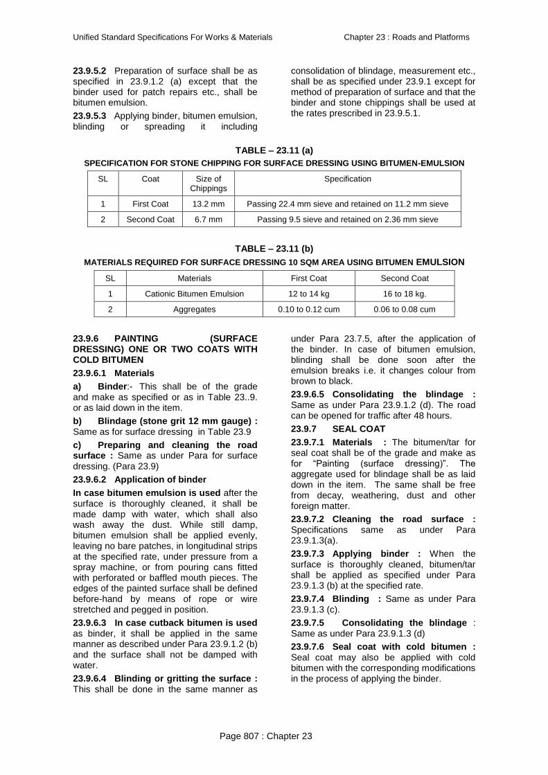
23.9.5.2 Preparation of surface shall be as specified in 23.9.1.2 (a) except that the binder used for patch repairs etc., shall be bitumen emulsion.
23.9.5.3 Applying binder, bitumen emulsion, blinding or spreading it including
consolidation of blindage, measurement etc., shall be as specified under 23.9.1 except for method of preparation of surface and that the binder and stone chippings shall be used at the rates prescribed in 23.9.5.1.
TABLE – 23.11 (a) SPECIFICATION FOR STONE CHIPPING FOR SURFACE DRESSING USING BITUMEN-EMULSION
SL Coat Size of Chippings
Specification
1 First Coat 13.2 mm Passing 22.4 mm sieve and retained on 11.2 mm sieve
2 Second Coat 6.7 mm Passing 9.5 sieve and retained on 2.36 mm sieve
TABLE – 23.11 (b)
MATERIALS REQUIRED FOR SURFACE DRESSING 10 SQM AREA USING BITUMEN EMULSION
SL Materials First Coat Second Coat
1 Cationic Bitumen Emulsion 12 to 14 kg 16 to 18 kg.
2 Aggregates 0.10 to 0.12 cum 0.06 to 0.08 cum
23.9.6 PAINTING (SURFACE DRESSING) ONE OR TWO COATS WITH COLD BITUMEN
23.9.6.1 Materials
a) Binder:- This shall be of the grade and make as specified or as in Table 23..9. or as laid down in the item.
b) Blindage (stone grit 12 mm gauge) : Same as for surface dressing in Table 23.9
c) Preparing and cleaning the road surface : Same as under Para for surface dressing. (Para 23.9)
23.9.6.2 Application of binder
In case bitumen emulsion is used after the surface is thoroughly cleaned, it shall be made damp with water, which shall also wash away the dust. While still damp, bitumen emulsion shall be applied evenly, leaving no bare patches, in longitudinal strips at the specified rate, under pressure from a spray machine, or from pouring cans fitted with perforated or baffled mouth pieces. The edges of the painted surface shall be defined before-hand by means of rope or wire stretched and pegged in position.
23.9.6.3 In case cutback bitumen is used as binder, it shall be applied in the same manner as described under Para 23.9.1.2 (b) and the surface shall not be damped with water.
23.9.6.4 Blinding or gritting the surface : This shall be done in the same manner as
under Para 23.7.5, after the application of the binder. In case of bitumen emulsion, blinding shall be done soon after the emulsion breaks i.e. it changes colour from brown to black.
23.9.6.5 Consolidating the blindage : Same as under Para 23.9.1.2 (d). The road can be opened for traffic after 48 hours.
23.9.7 SEAL COAT
23.9.7.1 Materials : The bitumen/tar for seal coat shall be of the grade and make as for ―Painting (surface dressing)‖. The aggregate used for blindage shall be as laid down in the item. The same shall be free from decay, weathering, dust and other foreign matter.
23.9.7.2 Cleaning the road surface : Specifications same as under Para 23.9.1.3(a).
23.9.7.3 Applying binder : When the surface is thoroughly cleaned, bitumen/tar shall be applied as specified under Para 23.9.1.3 (b) at the specified rate.
23.9.7.4 Blinding : Same as under Para 23.9.1.3 (c).
23.9.7.5 Consolidating the blindage : Same as under Para 23.9.1.3 (d)
23.9.7.6 Seal coat with cold bitumen : Seal coat may also be applied with cold bitumen with the corresponding modifications in the process of applying the binder.
Unified Standard Specifications For Works & Materials Chapter 23 : Roads and Platforms
Page 808 : Chapter 23
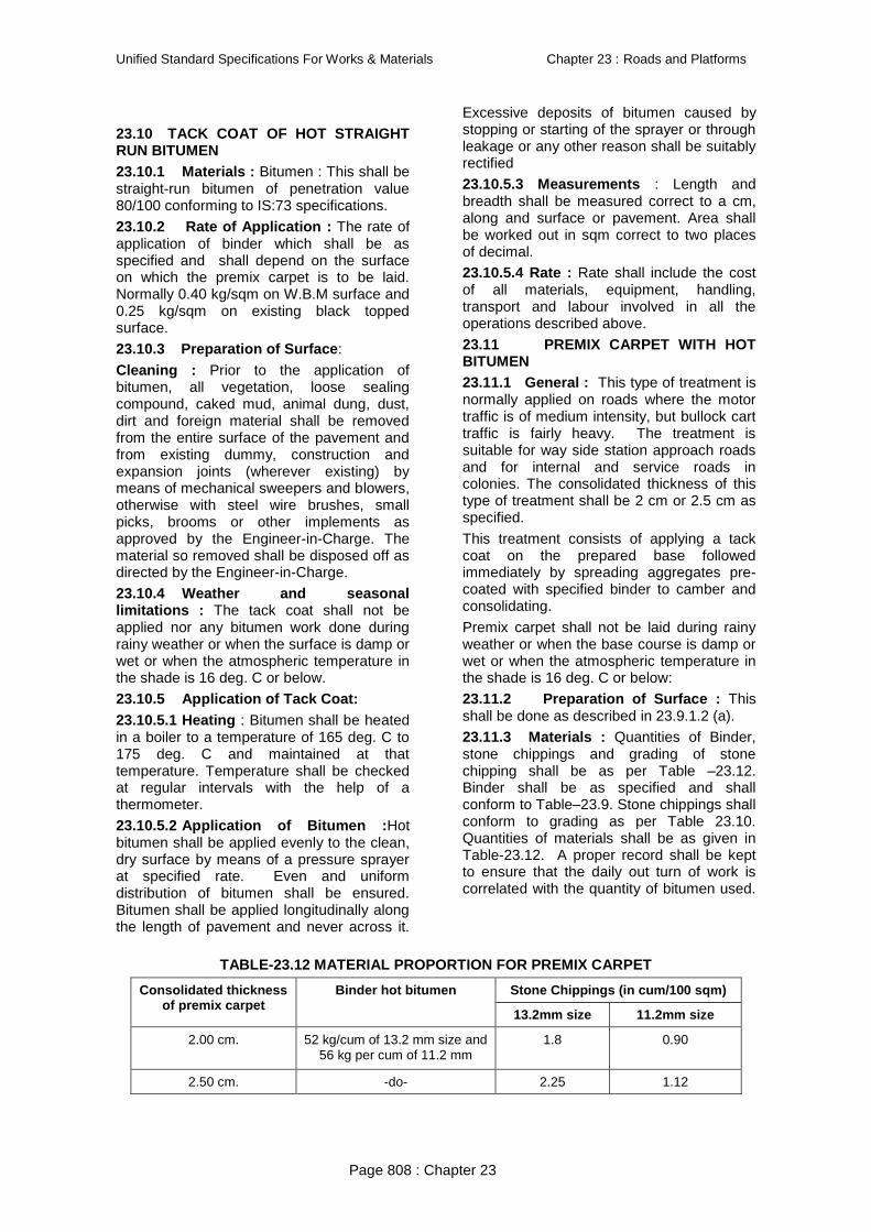
23.10 TACK COAT OF HOT STRAIGHT RUN BITUMEN
23.10.1 Materials : Bitumen : This shall be straight-run bitumen of penetration value 80/100 conforming to IS:73 specifications.
23.10.2 Rate of Application : The rate of application of binder which shall be as specified and shall depend on the surface on which the premix carpet is to be laid. Normally 0.40 kg/sqm on W.B.M surface and 0.25 kg/sqm on existing black topped surface.
23.10.3 Preparation of Surface:
Cleaning : Prior to the application of bitumen, all vegetation, loose sealing compound, caked mud, animal dung, dust, dirt and foreign material shall be removed from the entire surface of the pavement and from existing dummy, construction and expansion joints (wherever existing) by means of mechanical sweepers and blowers, otherwise with steel wire brushes, small picks, brooms or other implements as approved by the Engineer-in-Charge. The material so removed shall be disposed off as directed by the Engineer-in-Charge.
23.10.4 Weather and seasonal limitations : The tack coat shall not be applied nor any bitumen work done during rainy weather or when the surface is damp or wet or when the atmospheric temperature in the shade is 16 deg. C or below.
23.10.5 Application of Tack Coat:
23.10.5.1 Heating : Bitumen shall be heated in a boiler to a temperature of 165 deg. C to 175 deg. C and maintained at that temperature. Temperature shall be checked at regular intervals with the help of a thermometer.
23.10.5.2 Application of Bitumen :Hot bitumen shall be applied evenly to the clean, dry surface by means of a pressure sprayer at specified rate. Even and uniform distribution of bitumen shall be ensured. Bitumen shall be applied longitudinally along the length of pavement and never across it.
Excessive deposits of bitumen caused by stopping or starting of the sprayer or through leakage or any other reason shall be suitably rectified
23.10.5.3 Measurements : Length and breadth shall be measured correct to a cm, along and surface or pavement. Area shall be worked out in sqm correct to two places of decimal.
23.10.5.4 Rate : Rate shall include the cost of all materials, equipment, handling, transport and labour involved in all the operations described above.
23.11 PREMIX CARPET WITH HOT BITUMEN
23.11.1 General : This type of treatment is normally applied on roads where the motor traffic is of medium intensity, but bullock cart traffic is fairly heavy. The treatment is suitable for way side station approach roads and for internal and service roads in colonies. The consolidated thickness of this type of treatment shall be 2 cm or 2.5 cm as specified.
This treatment consists of applying a tack coat on the prepared base followed immediately by spreading aggregates pre-coated with specified binder to camber and consolidating.
Premix carpet shall not be laid during rainy weather or when the base course is damp or wet or when the atmospheric temperature in the shade is 16 deg. C or below:
23.11.2 Preparation of Surface : This shall be done as described in 23.9.1.2 (a).
23.11.3 Materials : Quantities of Binder, stone chippings and grading of stone chipping shall be as per Table –23.12. Binder shall be as specified and shall conform to Table–23.9. Stone chippings shall conform to grading as per Table 23.10. Quantities of materials shall be as given in Table-23.12. A proper record shall be kept to ensure that the daily out turn of work is correlated with the quantity of bitumen used.
TABLE-23.12 MATERIAL PROPORTION FOR PREMIX CARPET
Consolidated thickness of premix carpet
Binder hot bitumen Stone Chippings (in cum/100 sqm)
13.2mm size 11.2mm size
2.00 cm. 52 kg/cum of 13.2 mm size and 56 kg per cum of 11.2 mm
1.8 0.90
2.50 cm. -do- 2.25 1.12
Test4

Unified Standard Specifications For Works & Materials Chapter 23 : Roads and Platforms
Page 809 : Chapter 23
23.11.4 Tack Coat : The rate of application of binder for tack coat shall be as specified. The rate will be depending upon the surface on which the premix carpet is to be laid i.e. water bound macadam surface or existing black topped surface. Tack coat shall be applied as described in 23.10.5.
23.11.5 Preparation of Premix : The aggregate shall be dry and suitably heated to temperature as directed by Engineer-in-Charge before these are placed in the mixer to facilitate mixing with the binder.
Mixers of approved type shall be employed for mixing the aggregates with the bituminous binder.
The binder shall be heated to the temperature appropriate to the grade of bitumen approved by the Engineer-in-Charge, in boilers of suitable design avoiding local overheating and ensuring a continuous supply.
The aggregates shall be dry and suitably heated to a temperature as directed by Engineer-in-Charge before these are placed in the mixer. After about 15 seconds of dry mixing, the heated binder shall be distributed over the aggregates at the rate specified.
The mixing of binder with chippings shall be continued until the chippings are thoroughly coated with the binder. The mix shall be immediately transported from the mixer to the point of use in suitable vehicles or wheel barrows. The vehicles employed for transport shall be cleaned and be covered over in transit if so directed.
23.11.6 Spreading and Rolling : The premixed material shall be spread on the road surface with rakes to the required thickness and camber or distributed evenly with the help of a drag spreader, without any undue loss of time. The camber shall be checked by means of camber boards and inequalities evened out. As soon as sufficient length of bituminous material has
been laid, rolling shall commence with 6 to 9 tonne power rollers, preferably of smooth wheel tandon type, or other approved plant. Rolling shall begin at the edges and progress towards the centre longitudinally. Except on the super elevated portions rolling shall progress from the lower to upper edge, parallel to the centre line of the pavement. The consolidated thickness shall in no place be less than the specified thickness by more than 25%. However, the average shall not be less than that specified for the item in item.
When the roller has passed over the whole area once, any high spots or depressions, which become apparent shall be corrected by removing or adding premixed materials. Rolling shall then be continued until the entire surface has been rolled to compaction and all the roller marks eliminated. In each pass of the roller, preceding track shall be overlapped uniformly by at least 1/3 width. The roller wheels shall be kept damp to prevent the premix from adhering to the wheels and being picked up. In no case shall fuel/lubricating oil be used for this purpose.
Rollers shall not stand on newly laid material as it may get deformed thereby.
The edges along and transverse of the carpet, laid and compacted earlier shall be cut to their full depth so as to expose fresh surface which shall be painted with a thin surface coat of appropriate binder before the new mix is placed against it.
Further, the prepared finished surface shall be protected from traffic for 24 hours or such period as may be specified by the Engineer.
23.11.7 Surface Finishing :The surface regularity both in longitudinal and transverse directions shall be within the tolerances specified in Table 23.13.
TABLE – 23.13 TOLERANCE IN SURFACE FINISHING
Longitudinal profile Cross profile
Max. permissible undulation when measured with 3 M straight edge
Max. permissible variation from specified profile when measured with a camber template
10 mm 6 mm
The longitudinal profile shall be checked during rolling with a three metres long straight edge and graduated wedge at the middle of each traffic lane along the road. Similarly the transverse profile shall be checked with adjustable templates at intervals of 10 metres.
Test5
Unified Standard Specifications For Works & Materials Chapter 23 : Roads and Platforms
Page 810 : Chapter 23
23.11.8 Rectification : Where the surface irregularity falls outside the specified tolerances the contractor shall be liable to rectify it to the satisfaction of Engineer by adding fresh material and recompacting to specifications where the surface is low. Where the surface is high the full depth of the layer shall be removed and replaced with fresh material and compacted and finished to specifications.
23.11.9 Measurements : The length and width of the finished work shall be measured correct to a cm along the finished surface of the road. The area shall be calculated in square metre, correct to two places of decimal.
23.11.10 Rate : The rate shall include the cost of materials and labour involved in all the operations described above for the particular item, except for the cost of ―Repairs described under Para 23.9.1.2 (a).‖
23.12 PREMIX CARPET WITH BITUMEN EMULSION
23.12.1 General : This type of work is not ordinarily recommended but may be done in case of urgent repairs under damp conditions.
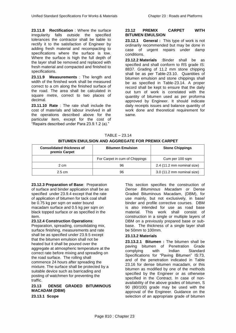
23.12.2 Materials :Binder shall be as specified and shall conform to RS grade IS: 8837. Grading of 11.2 mm stone chipping shall be as per Table-23.10. Quantities of bitumen emulsion and stone chippings shall be as specified in Table-23.14. A proper record shall be kept to ensure that the daily out turn of work is correlated with the quantity of bitumen used as per proforma approved by Engineer. It should indicate daily receipts issues and balance quantity of work done and theoretical requirement for same.
TABLE – 23.14
BITUMEN EMULSION AND AGGREGATE FOR PREMIX CARPET
Consolidated thickness of premix Carpet
Bitumen Emulsion Stone Chippings
For Carpet in cum of Chippings Cum per 100 sqm
2 cm 96 2.4 (11.2 mm nominal size)
2.5 cm 96 3.0 (11.2 mm nominal size)
23.12.3 Preparation of Base: Preparation of surface and binder application shall be as specified under 23.9.4 except that the rate of application of bitumen for tack coal shall be 0.75 kg per sqm on water bound macadam surface and 0.5 kg per sqm on black topped surface or as specified in the item. 23.12.4 Construction Operations: Preparation, spreading, consolidating mix, surface finishing, measurements and rate shall be as specified under 23.9.5 except that the bitumen emulsion shall not be heated but it shall be poured over the aggregate at atmospheric temperature at the correct rate before mixing and spreading on the road surface. The rolling shall commence 24 hours after spreading the mixture. The surface shall be protected by a suitable device such as barricading and posting of watchmen for preventing the traffic.
23.13 DENSE GRADED BITUMINOUS MACADAM (DBM)
23.13.1 Scope
This section specifies the construction of Dense Bituminous Macadam or Dense Graded Bituminous Macadam, (DBM), for use mainly, but not exclusively, in base/ binder and profile corrective courses. DBM is also intended for use as road base material. This work shall consist of construction in a single or multiple layers of DBM on a previously prepared base or sub-base. The thickness of a single layer shall be 50mm to 100mm.
23.13.2 Materials
23.13.2.1 Bitumen : The bitumen shall be paving bitumen of Penetration Grade complying with Indian Standard Specifications for ―Paving Bitumen‖ IS:73, and of the penetration indicated in Table 23.16 for dense bitumen macadam, or this bitumen as modified by one of the methods specified by the Engineer or as otherwise specified in the Contract. In case of non-availability of the above grades of bitumen, S 90 (80/100) grade may be used with the approval of the Engineer. Guidance on the selection of an appropriate grade of bitumen

Unified Standard Specifications For Works & Materials Chapter 23 : Roads and Platforms
Page 811 : Chapter 23
is given in the Manual for Construction and Supervision of Bituminous works.
23.13.2.2 Coarse aggregates : The coarse aggregates shall consist of crushed rock, crushed gravel or other hard material retained on the 2.36 mm sieve. They shall be clean, hard, durable, of cubical shape, free from dust and soft or friable matter, organic or other deleterious substances. Where the Contractor‘s selected source of aggregates have poor affinity for bitumen, as a condition for the approval of that source, the bitumen shall be treated with an approved anti-stripping agent, as per the manufacturer‘s recommendations, without additional payment. Before approval of the source, the aggregates shall be tested for stripping. The aggregates shall satisfy the physical requirements specified for dense bituminous macadam.
Where crushed gravel is proposed for use as aggregate, not less than 90% by weight of
the crushed material retained on the 4.75mm sieve shall have at least two fractured faces.
23.13.2.3 Fine aggregates : Fine aggregates shall consist of crushed or naturally occurring mineral material, or a combination of the two, passing the 2.36mm sieve and retained on the 75 micron sieve. They shall be clean, hard, durable, dry and free from dust, and soft or friable matter, organic or other deleterious matter.
The fine aggregate shall have a sand equivalent value of not less than 50 when tested in accordance with the requirement of IS:2720 (Part 37).
The plasticity index of the fraction passing the 0.425mm sieve shall not exceed 4 when tested in accordance with IS:2720 (Part 5).
23.13.2.4 Filler : Filler shall consist of finely divided mineral matter such as rock dust, hydrated lime or cement approved by the Engineer. The filler shall be graded within the limits indicated in Table 23.15.
TABLE 23.15 GRADING REQUIREMENTS FOR MINERAL FILLER
IS Sieve (mm) Cumulative per cent passing by weight of total aggregate
0.6 100
0.3 95-100
0.075 85-100
The filler shall be free from organic impurities and have a Plasticity Index not greater than 4. The Plasticity Index requirement shall not apply if filler is cement or lime. When the coarse aggregate is gravel, 2 per cent by weight of total aggregate, shall be Portland cement or hydrated lime and the percentage of fine aggregate reduced accordingly. Cement or hydrated lime is not required when the limestone aggregate is used. Where the aggregates fail to meet the requirements of the water sensitivity test in Table 500-8, then 2 per cent by total weight
of aggregate, hydrated lime shall be added without additional cost.
23.13.2.5 Aggregate grading and binder content: When tested in accordance with IS:2386 Part 1 (wet sieving method), the combined grading of the coarse and fine aggregates and added filler for the particular mixture shall fall within the limits shown in Table 23.16, for dense bituminous macadam grading 1 or 2 as specified in the Contract. The type and quantity of bitumen, and appropriate thickness, are also indicated for each mixture type.
Table 23.16 COMPOSITION OF DENSE GRADED BITUMINOUS MACADAM PAVEMENT LAYERS
Grading 1 2
Nominal aggregate size 40mm 25mm
Layer Thickness 80-100mm 50-75mm
IS Sieve (mm) Cumulative % by weight of total aggregate passing
45 100
37.5 95-100 100
26.5 63-93 90-100
19 -- 71-95
13.2 55-75 56-80
9.5 -- --

Unified Standard Specifications For Works & Materials Chapter 23 : Roads and Platforms
Page 812 : Chapter 23
4.75 38-54 38-54
2.36 28-42 28-42
1.18 -- --
0.6 -- --
0.3 7-21 7-21
0.15 -- --
0.075 2-8 2-8
Bitumen content % by mass of total mix 2
Min 4.0 Min –5.0
Bitumen grade (pen) 65 or 90 65 or 90
Notes : 1. The combined aggregate grading shall not vary from the low limit on one sieve to the high limit on the adjacent sieve, determined by the Marshall method.
23.13.3 Mixture Design
23.13.3.1 Requirement for the mixture : Apart from conformity with the grading and quality requirements for individual ingredients, the mixture shall meet the requirements set out in Table 23.17.
TABLE 23.17 REQUIREMENTS FOR DENSE GRADED BITUMINOUS MACADAM
Minimum stability (kN at 60o C) 9.0
Minimum flow (mm) 2
Maximum flow (mm) 4
Compaction level (Number of blows) 75 blows on each of the two faces of the specimen
Per cent air voids 3-6
Per cent voids in mineral aggregate (VMA) See Table 23.18 below
Per cent voids filled with bitumen (VFB) 65-75
The requirements for minimum per cent voids in mineral aggregate (VMA) are set out in Table 23.18.
TABLE 23.18 MINIMUM PER CENT VOIDS IN MINERAL AGGREGATE (VMA)
Nominal Maximum Particle Size1 mm)
Minimum VMA, Per cent Related to Design Air Voids, Per cent2
3.0 4.0 5.0
9.5 14.0 15.0 16.0
12.5 13.0 14.0 15.0
19.0 12.0 13.0 14.0
25.0 11.0 12.0 13.0
37.5 10.0 11.0 12.0
Notes : The nominal maximum particle size is one size larger than the first sieveto retain more than 10 per cent.Interpolate minimum voids in the mineral aggregate (VMA) for design air voids values between those listed.
23.13.3.2 Binder Content : The binder content shall be optimised to achieve the requirements of the mixture set out in Table 23.21 and the traffic volume specified in the Contract. The Marshall method for determining the optimum binder content shall be adopted as described in. The Asphalt Institute Manual MS-2, replacing the aggregates retained on the 26.5mm sieve by the aggregates passing the 26.5mm sieve
and retained on the 22.4 mm sieve, where approved by the Engineer.
23.13.3.3 Job mix formula : The Contractor shall inform the Engineer in writing, atleast 20 days before the start of the work, of the job mix formula proposed for use in the works, and shall give the following details.
1. Source and location of all materials
2. Proportions of all materials expressed as follows where each is applicable
3. Binder type and percentage by weight of total mixture

Unified Standard Specifications For Works & Materials Chapter 23 : Roads and Platforms
Page 813 : Chapter 23
4. Coarse aggregate / Fine aggregate / Mineral filler as percentage by weight of total aggregate including mineral filler.
5. A single definite percentage passing each sieve for the mixed aggregate
6. The individual gradings of the individual aggregate fractions and thee proportion of each in the combined grading
7. The results of tests as obtained by the Contractor.
8. Where the mixer is a batch mixer, the individual weights of each type of aggregate, and binder per batch.
9. Test results of physical characteristics of aggregates to be used
10. Mixing temperature and compacting temperature.
While establishing the job mix formula, the Contractor shall ensure that it is based on a correct and truly representative sample of the materials that will actually be used in the work and that the mixture and its different ingredients satisfy the physical and strength requirements of these Specifications.
Approval of the job mix formula shall be based on independent testing by the Engineer for which samples of all ingredients of the mix shall be furnished by the Contractor as required by the Engineer.
The approved job mix formula shall remain effective unless and until a revised Job Mix Formula is approved. Should a change in the source of materials to be proposed, a new job mix formula shall be forwarded to the Engineer for approval before the placing of the material.
23.13.3.4 Plant trials – permissible variation in job mix formula :
Once the laboratory job mix formula is approved, the Contractor shall carry out plant trials at the mixer to establish that the plant can be set up to produce a uniform mix conforming to the approved job mix formula. The permissible variations of the individual percentages of the various ingredients in the actual mix from the job mix formula to be used shall be within the limits as specified in Table 23.19. These variations are intended to apply to individual specimens taken for quality control tests.
TABLE 23.19 PERMISSIBLE VARIATIONS FROM THE JOB MIX FORMULA
Description Permissible variation
Base/binder course Wearing course
Aggregate passing 19mm sieve or larger + 8% + 7%
Aggregate passing 13.2mm, 9.5mm + 7% + 6%
Aggregate passing 4.75mm + 6% + 5%
Aggregate passing 2.36mm, 1.18mm, 0.6mm + 5% + 4%
Aggregate passing 0.3mm, 0.15mm + 4% + 3%
Aggregate passing 0.075mm + 2% + 1.5%
Binder content + 0.3% + 0.3%
Mixing temperature + 10oC + 10oC
Once the plant trials have demonstrated the capability of the plant, and the trials are approved, the laying operation may commence. Over the period of the first month of production for laying on the works, the Engineer shall require additional testing of the product to establish the reliability and consistency of the plant.
23.13.3.5 Laying Trials
Once the plant trials have been successfully completed and approved, the Contractor shall carry out laying trials, to demonstrate that the proposed mix can be successfully laid, and compacted. The laying trial shall be carried out on a suitable area which is not to form part of the works, unless specifically approved in writing, by the Engineer. The
area of the laying trials shall be a minimum of 100 sqm of construction similar to that of the project road, and it shall be in all respects, particularly compaction, the same as the project construction, on which the bituminous material is to be laid.
23.13.3.6 The Contractor shall previously inform the Engineer of the proposed method for laying and compacting the material. The plant trials shall then establish if the proposed laying plant, compaction plant, and methodology is capable of producing satisfactory results. The density of the finished paving layer shall be determined by taking cores, no sooner than 24 hours after laying, or by other approved method.

Unified Standard Specifications For Works & Materials Chapter 23 : Roads and Platforms
Page 814 : Chapter 23
Once the laying trials have been approved, the same plant and methodology shall be applied to the laying of the material on the project, and no variation of either shall be acceptable, unless approved in writing by the Engineer, who may at his discretion require further laying trials.
23.13.4 Construction Operations
23.13.4.1 Weather and seasonal limitations: The provisions of Clause 23.13.3.1 shall apply.
23.13.4.2 Preparation of base : The base on which Dense Graded Bituminous Material is to be laid shall be prepared in accordance with Para 23.9.1.2 (a) and (b) as appropriate, or as directed by the Engineer. The surface shall be thoroughly swept clean by a mechanical boom, and the dust removed by compressed air. In locations where mechanical broom cannot access, other approved methods shall be used as directed by the Engineer.
23.13.4.3 Geosynthetics : Where Geosynthetics are specified in the Contract this shall be in accordance with the requirements stated in relevant supplier‘s specifications or as per Engineer‘s instructions..
23.13.4.4 Stress absorbing layer : Where a stress absorbing layer is specified in the Contract, this shall be applied in accordance with the requirements stated in relevant specifications or as per Engineer‘s instructions..
23.13.4.5 Prime Coat : Where the material on which the dense bituminous macadam is to be laid is other than a bitumen bound layer, a prime coat shall be applied, as specified, in accordance with the provisions of Para 23.9.1.2 (b), or as directed by the Engineer.
23.13.4.6 Tack coat : Where the material on which the dense bituminous macadam is to be placed is a bitumen bound surface, a tack coat shall be applied as specified, in accordance with the provisions of Para 23.10, or as directed by the Engineer.
23.13.4.7 Mixing and transportation of the mixture : The provisions as specified in Para 23.13.3.4.
23.13.4.8 Spreading : The provisions of Clause 23.13.3.5 shall apply.
23.13.4.9 Rolling : The general provisions of Clauses 23.13.3.6 shall apply, as modified by the approved laying trials. The
compaction process shall be carried out by the same plant, and using the same method, as approved in the laying trials, which may be varied only with the express approval of the Engineer in writing.
23.13.5 Opening to Traffic
The newly laid surface shall not be open to traffic for at least 24 hours after laying and completion of compaction, without the express approval of the Engineer in writing.
23.13.6 Surface Finish and Quality Control of work
The surface finish of the completed construction shall conform to the requirements of Para 23.13.4.
23.13.7 Arrangements for Traffic
During he period of construction, arrangements for traffic shall be made in accordance with the directions of the Engineer.
23.13.8 Measurement for Payment Dense Graded Bituminous Materials shall be measured as finished work either in cum or by the sqm at a specified thickness as detailed on the Contract drawings, or as directed by the Engineer.
23.13.9 Rate
The contract unit rate for Dense Graded Bituminous Macadam shall be payment in full for carrying out the all required operations as specified, and shall include, but not necessarily limited to all components listed in Para 23.13.8. The rate shall include the provision of bitumen, at the rates specified in the relevant item by weight of the total mixture. The variance in actual percentage of bitumen used will be assessed and the payment adjusted, up or down, accordingly.
23.14 CEMENT CONCRETE PAVEMENT UNDER CONTROLLED CONDITIONS
23.14.1 Generally All specification given in concrete chapter shall be applicable except those given below.
23.14.2 Grading of mixed aggregates : The grading of all ingredients (coarse and fine aggregates) to be used in the work shall be determined in the laboratory. The coarse and fine aggregates shall be mixed in suitable proportions so that the grading of the mixed aggregates shall be in the range indicated in Table-23.20.

Unified Standard Specifications For Works & Materials Chapter 23 : Roads and Platforms
Page 815 : Chapter 23
TABLE- 23.20
I.S. Sieve Size (IS: 460) % age passing by weight
45 mm
22.4 mm
11.2 mm
5.6 mm
2.8 mm
1.4 mm
710 microns
355 microns
180 microns
100
55-60
45-50
35-40
30-35
20-25
15-20
10-14
2-5
23.14.3 No concrete shall be laid nor any payment made thereof unless the concrete mix design is obtained by the contractor and got approved from the Engineer in writing. This mix design shall be provisional and subject to obtaining satisfactory results with trial mixes.
23.14.4 Placing of concrete
23.14.4.1 The concrete is to be transported without any delay from place of mixing to the position of laying and any concrete which in the opinion of the Engineer-in–Charge has remained in mixed state more than half an hour before reaching the place of laying is to be rejected and removed from site. In case of RMC, modified instructions shall be issued by the Chief Engineer.
23.14.4.2 The concrete is to be deposited and spread to such a depth that when compacted and finished the slab thickness indicated will be obtained at all points and the surface will not at any point be below the level specified for the finished surface, in order to secure adequate compaction, the concrete is to be spread so as to stand proud of the finished surface level and produce a surcharge. With screed and internal vibrators, slabs of thickness not exceeding 15 cm shall be laid on one layer. Concrete for slabs of greater thickness will be laid in two layers. The second layer will be laid over the unfinished but thoroughly compacted first layer within the initial setting time of cement used in the concrete. Second layer shall also be compacted thoroughly after laying.
23.14.4.3 Concrete shall be deposited in such a manner as to require as little handling as possible. Spreading, compacting and finishing (except final broom/belt finishing) operations shall be completed within a period not exceeding half an hour from the time the mixing starts or as specified otherwise in case of RMC. In case of dry and hot
weather this time shall not exceed 25 minutes.
23.14.5 Finishing of concrete
During compaction, any low or high spots shall be made up by adding or removing concrete. After longitudinal floating has been completed but while concrete is still plastic, the slab surface shall be tested for trueness with a 3 m straight edge. Any depressions or high spots showing departure from the true surface shall be immediately rectified. High spots shall be cut down and refinished. Depressions shall be enlarged to about 8–10 cm and filled up with fresh concrete, compacted and finished.
23.14.5.1 The straight edge testing the re-floating is to continue until the entire surface —
(a) is free from observable departure from the straight edge.
(b) Conforms to the required levels and cross section, and
(c) Shall conform to the specified surface when the concrete has hardened.
23.14.5.2 The foregoing work is to be carried out while the concrete is still plastic and workable.
23.14.6 Belting
Just before concrete becomes non-plastic, the surface shall be belted with a two ply canvas belt not less than 20 cm wide and at least 1 metre longer than the width of the slab. Hand belts shall have suitable handles to permit controlled uniform manipulation. The belt shall be operated with short strokes transverse to the centre line of the pavement and with rapid advance parallel to the centre line.
23.14.7 Brooming
After belting and as soon as the surplus water if any, has risen to the surface, the pavement shall be given a broom finish with

Unified Standard Specifications For Works & Materials Chapter 23 : Roads and Platforms
Page 816 : Chapter 23
an approved steel or fiber broom not less than 45 cm wide. The broom shall be pulled gently over the surface of the pavement from edge to edge. Adjacent strokes shall be slightly overlapped. Brooming shall be perpendicular to the centre line of the pavement and so executed that the corrugations formed shall be uniform in character and width and not more than 1.5 mm deep.
Brooming shall be completed before the concrete reaches such a stage that the surface is likely to be torn or unduly roughened by the operation. The broomed surface shall be free from porous or rough spots, irregularities, depressions, and small pockets such as may be caused by accidental disturbing of particles of coarse aggregates embodied near the surface. The brooming shall be of uniform pattern all through.
23.14.8 Edging
After belting/brooming has been completed but before the initial setting of concrete, the edges of the slab shall be carefully finished with an edger of 6 mm radius, and the pavement edges shall be left smooth and true to line.
23.14.9 Honey combing
The side forms shall not be removed until 12 hours or such longer period as the Engineer-in-Charge may decide after the laying of concrete. As soon as the side forms are removed, any minor honey combed area shall be filled with mortar composed of one part of cement and two parts of fine aggregate. Major honey combing areas or segregated concrete or other defective work or areas damaged by removal of the forms or concrete damaged by rain or due to any other reason whatsoever shall be considered as defective work and shall be removed and replaced by the contractor at his own expense. The total area of honeycombed surface shall not exceed 4 per cent of the area of the slab side. However, no individual honeycomb patch shall exceed 0.1 sqm. Engineer-in-Charge‘s decision as to whether the concrete is defective or not shall be final and binding.
23.14.10 Surface Accuracy
23.14.10.1 After the concrete has sufficiently hardened for about 12 hours and not later than 24 hours, the surface shall be tested again for high spots. All high spots shall be marked and those exceeding 3 mm shall be ground down immediately. Care shall be
taken to see that the grinding does not in any way damage the concrete surface.
23.14.10.2 The final surface finish is to be such that when tested with a profilograh/ roughness indicator/or a 3 metre long straight edge or an equivalent mechanical unevenness indicator placed anywhere within the same or adjoining slab in any direction on the surface, there shall be no variation greater than 3 mm.
23.14.10.3 If the surface irregularity exceeding 3 mm still remains despite grinding as per Para 23.17.14.1 the concrete shall be removed to its full depth. The area of concrete to be removed shall be complete slab between the nearest joints and where the defective slab is less than 4.5 metres from the expansion joint, the whole area upto the expansion joint shall be removed to the full depth. The concrete so removed shall not be reused in the work. Fresh concrete shall be laid in the manner already described in these specifications and shall again be subject to test for surface accuracy and other quality control measures. Nothing extra shall be paid for the same.
23.14.10.4 Every slab shall bear an impression not exceeding 3 mm in depth comprising the number allotted to the slab and the date on which it is laid. This impression shall be formed by the contractor when the concrete is green so as to leave permanent mark on setting.
23.14.11 Construction Joints
Construction joints shall be provided as shown in the drawing and also at places where concreting is stopped due to unforeseen circumstances. The joints shall be straight and vertical through the full thickness of the slab. While concrete in adjacent bay is still green, flats of suitable size shall be drawn along the edge and a groove of size 10mm x 25 mm deep shall be neatly formed and finished. The edges of the groove shall be full nosed. After curing of concrete is complete, this groove shall be thoroughly cleaned of all sand dust and shall be perfectly dried and filled with hot poured sealing compound conforming to Grade B of IS: 1834. Before filling with sealing compound the faces of concrete of the joint shall be coated with Shalijet primer or equivalent to a depth of 25 mm at the rate of 2.6 litres per 10 square meters.
23.14.12 Dummy Joints
23.14.12.1 The joints shall be 10 mm wide and shall extend vertically from the surface of the slab to be depth equal to 1/3rd of the

Unified Standard Specifications For Works & Materials Chapter 23 : Roads and Platforms
Page 817 : Chapter 23
thickness of the slab but not less than 4 cm in any case. The joint may be formed by depressing into the soft but compacted concrete a high tensile M.S. or other approved Tee or flat bar of depth not less than required depth of the joint plus 25 mm. The bar used for forming the groove shall be coated with soft soap or other suitable lubricant to facilitate its removal when the steel Tee or flat is removed. Joints shall be neatly formed with proper tools and mortar material from the slab itself. No additional cement mortar (rich or otherwise) shall be used.
23.14.12.2 Cutting or sawing by a saw mounted on a movable frame and driven mechanically shall also be permitted as a method for making the dummy joint. In this case the width may be reduced to 6 mm. Any other method for making joints can be followed with the prior approval of the Engineer-in-Charge.
23.14.12.3 In all cases, except where cutting is done with saw, the joint edges shall be bullnosed. Care should be taken to see that the edges of the grooves are not damaged.
23.14.12.4 The grooves shall be filled with hot poured sealing compound conforming to Grade B of IS: 1834. Prior to filling with sealing compound, the joints shall be cleaned by compressed air and primed with Shalijet primer or equivalent .
23.14.12.5 All joints shall be sealed as soon as practicable after 28 days of placing of slabs. Joints shall be sealed flush with the adjacent pavement surface in summer and 3-4 mm below finished concrete surface in winter. The pavement shall be opened to traffic only after joint sealing over the entire pavement. To prevent tackiness or pickup under traffic, the exposed surfaces of the sealing compound shall be dusted with hydrated lime, if directed by Engineer, for which nothing extra shall be paid to the contractor.
23.14.12.6 In case of sudden rain or storm, the work can be concluded at the dummy joints but these will then be formed as construction joints.
23.14.12.7 Before sealing of joints, it may be ensured that the groove extends fully across the bay between consecutive longitudinal joints, in the case of transverse joints. Any concrete or other foreign matter must be removed from the groove.
23.14.13 Defects Liability Period
This period shall be reckoned in the case of concrete pavement work as one year from the date of completion of work or as specified otherwise and it shall be the liability of the contractor to repair, strengthen or reconstruct any portion of the work which has shown damage or any defect, arising out of any bad workmanship or defective material used in the work during this period. In the case of this rectification not being commenced by the contractor within 7 days from the date of notice from the Engineer and completed expeditiously the Engineer reserves the right to get the repair work executed at the risk and cost of the contractor.
23.14.14 Measurements
23.14.14.1 For the purpose of ascertaining the quantity of concrete in the pavement, thickness shall be measured by means of a scale correct to the nearest 2 mm. The thickness of the concrete pavement slabs shall be taken on either side of the pavement at each dummy joint at four corners of the slab immediately after removal of the side forms. In case the average thickness of the slab exceeds the specified thickness, payment shall be restricted to the specified thickness. Payment will be made in cum corrected to two decimals unless otherwise specified.
23.14.14.2 The dimensions of each slab of pavement shall be measured as follows to the nearest 5 mm.
(a) Length
(i) Between the end of a pavement to the centre line of the expansion joints
(ii) Between the centre lines of consecutive expansion joints.
(b) Width
(i) Between the edge of a pavement and the centre line of the construction joints.
(ii) Between the centre lines of construction joints and expansion joints.
(iii) Between the centre lines of consecutive construction joints.
Note : The quantity of concrete in the pavement slab shall be worked out by multiplying the area of the slab and its average thickness or specified thickness whichever is less. No deduction shall be made for any joints in the concrete slab.
23.14.14.3 Measurements of concrete slabs shall be recorded jointly by the Engineer or his authorized subordinate and the contractor or his authorized agent.
23.14.15 Rate

Unified Standard Specifications For Works & Materials Chapter 23 : Roads and Platforms
Page 818 : Chapter 23
The rate of the item for concrete in pavement shall include the cost of all materials and labour including charges for form work machinery tools & plants in all the operations described above. Rate includes provision of all joints specified above including infilling. The rate also includes all cost of setting up the laboratory at site and carrying out the quality control measures/tests enumerated above by the contractor at his own cost in the presence of Engineer or his authorized representative and submission of test results on completion of tests to the Engineer thereof.
23.14.16 Expansion Joint (With Non Extruding Filler Pad) in Concrete Pavements
23.14.16.1 Materials
Pre-moulded Joint Filler:It shall conform to IS: 1838 (Pt. I). The thickness shall be 20 mm and shall be of the maximum available standard length.
Joint sealing compound : The joint sealing compound shall be fuel and heat resistant type complying to grade B of IS: 1834. It shall be capable of adhering to the concrete without cracking, spalling and disintegration.
Primer : It shall be Shalijet or Expanjet primer or equivalent. Bituminous emulsions shall not be used as primers.
23.14.16.2 Construction Procedure
Expansion joints shall be provided as shown in the drawing and as per directions of Engineer-in-Charge. All joints shall be constructed true to line with their faces perpendicular to the surface of the pavement. The joint shall be 20 mm wide. The depth of the non-extruding filler paid shall be 25 mm less than the depth of the concrete slab.
Before the provision of expansion joint, the face of the already laid concrete slab shall be painted with primer at the rate of 2.6 liters per 10 square metres. The expansion pad shall be properly cut to shape and shall then be placed in position abutting the painted face of the already laid concrete slab. The adjacent slab shall then be concreted. The face of the pad against which the new concrete slab is to be laid shall also be painted with primer before laying the concrete, while concreting a neat groove 20 mm x 25 mm as per drawing shall be formed on top of the pad taking care that the edges are absolutely straight and that the groove so made does not get filled with any materials like concrete, mortar and other rubbish.
Before the curing process is started, the top of expansion joint shall be filled with bitumen sand mixture in order to ensure that no foreign material used in curing enters into the joint. This filling shall be removed before filling the joints with sealing compound.
For sealing the joints following operations shall be carried out:-
(a) The joints are cleared of any foreign matter to the full depth upto the top of expansion pad with steel spatula.
(b) The joints are blown with compressed air.
(c) Cleaning is done with Kerosene oil.
(d) Priming is done with spray gun @ 2.6 liters per 10 sqm of the surface to be primed
(e) The primer is allowed to dry completely before pouring the sealing compound.
(f) The sealing compound grade ‗A‘ is heated to the required temperature ranging between 155 deg. C to 165 deg. C or to the temperature range specified by the manufacturer. Over heating shall be avoided. Pouring shall be done from vessel with spout in such a manner that the material will not get spilled on the exposed surface of the concrete, any excess filler on the surface of the pavement shall be removed immediately and the pavement surface cleaned.
(g) The filling shall be worked in to the joints with hot flats to ensure escape of trapped air.
(h) The filling is then ironed with hot iron. It is recommended that while in summer the joints may be sealed flush with the adjacent pavement surface, in winter the sealing compound may be filled to a depth 3-4 mm below the surface.
(i) The edges of the joints are then cut and trimmed to ensure neat and straight-line finish.
(j) To prevent tackiness or pick up under traffic, the exposed surfaces of the sealing compound shall be dusted with hydrated lime, if so directed by Engineer (Nothing extra shall be paid for the same).
23.14.16.3 Measurements
The measurement of the specified depth of joint shall be recorded in metres correct to two places of decimals.
23.14.16.4 Rate
Rate for the item shall include the cost of all materials, plant, machinery and labour

Unified Standard Specifications For Works & Materials Chapter 23 : Roads and Platforms
Page 819 : Chapter 23
involved in all operations described above, including all cartages and lifts.
23.15 BLACK TOPPED SURFACE ON PLATFORMS (HOT PROCESS)
23.15.1 Base : The base may be made the same way as for cold process except that it should be finished 25 mm below the top level of the finished platform surface.
23.15.2 Priming coat/Tack coat : If the base consists of non-absorbant surfaces such as lateriate, kankar or moorum or clay gravel, a priming coat of approved make shall be applied. This shall be allowed to soak into the platform surface for 48 hours.
In case of brick ballast surface (or stone ballast surface), a tack coat shall be applied as detailed in Para 23.10.
23.15.3 Bitumastic Sheet : 25 mm thick carpet of bitumastic sheet (shel-sheet) shall then be laid.
23.15.4 Limitation : Since having a special bitumen mixer of the paddle type is essential for mixing of the aggregates and binder, shell- sheet carpet on platform can be laid only at important and zonal / divisional headquarter stations where the paddle mixer is available. A 6 to 8 tonnes power roller is also preferable though a 3 to 4 tonnes hand roller can serve the purpose, if approved by Engineer.
23.16 PAINTING ROAD/MARKINGS
23.16.1 Materials
23.16.1.1 Special Road marking paint of approved brand and manufacture shall be used. The paint shall conform to IS: 164. Ready mixed paint as received from the manufacturer shall be used without adding any admixture.
23.16.1.2 During work, if the consistency of the paint gets thick and thinning becomes necessary it shall be done by use of thinner of the specific brand of paint recommended by the manufacturer and with the approval of the Engineer.
23.16.1.3 The paint shall be brought to the site of work by the contractor in original sealed containers. The material shall be brought in one lot in adequate quantity to suffice for the entire work. The material shall be kept in the joint custody of the contractor and the Engineer. The empties shall not be removed from the site of work, till the work has been completed and permission obtained from the Engineer-in-Charge.
23.16.2 Preparation of surface
The surface shall be thoroughly cleaned and dusted. All the dirt, scales, oil and grease
shall be thoroughly removed before painting is started. The prepared surface shall be inspected and approved by the Engineer-in-Charge before painting is commenced.
23.16.3 Application
23.16.3.1 Before pouring into smaller containers for use, the paint shall be stirred thoroughly in its original container.During use also, it shall be continuously kept stirred.
23.16.3.2 The painting shall be applied evenly and smoothly by means of crossing and laying off. The crossing and laying off consists of covering the area over with paint, brushing the surface hard for the first time over and then brushing alternately in opposite direction, two or three times and then finally brushing lightly in a direction at right angle to the same. In this process, no brush marks shall be left after the laying off is finished. The full process of crossing and laying off will constitute one coat.
23.16.3.3 Each coat shall be allowed to dry out thoroughly before the next coat is applied.
23.16.3.4 Earlier applied coat shall be cleaned off dust before the next coat is laid.
23.16.3.5 No left over paint shall be put back into the stock tins. When not in use, the containers shall be kept properly closed.
23.16.3.6 No hair marks from the brush or clogging of paint puddles shall be left on the work.
23.16.3.7 The surface shall ordinarily not be painted until it has dried up completely. Trial patches of paint shall be laid at intervals to check if drying is satisfactory.
23.16.3.8 Marking on Roads shall be in accordance with the drawings or specifications prepared based on IRC standards. It should be done using templates, unless otherwise permitted by the Engineer.
23.16.4 Brushes and Containers
23.16.4.1 After work, the brushes shall be completely cleaned of paint by rinsing with turpentine. A brush in which paint has dried up is spoiled and shall on no account be reused for painting work. On no account kerosene oil shall be used for washing the brushes.
23.16.4.2 When the paint has been used, the containers shall be washed with turpentine and wiped dry with soft clean cloth so that they are clean, and can be used again.
23.16.5 Measurement
23.16.5.1 Length and breadth shall be measured correct to a cm. Area shall be

Unified Standard Specifications For Works & Materials Chapter 23 : Roads and Platforms
Page 820 : Chapter 23
worked out in square metre of painted area, correct to two places of a decimal.
23.16.6 Rate
23.16.6.1 Rate shall include cost of all materials, tools and labour involved inall the operations described above including all cartages, temporary protection and barricading till the paint dries if required, and all miscellaneous works.
23.17 BAJRI PATHS
23.17.1 Preparation of Sub-Grade
The formation for a width equal to that of the bajri path shall first be cut to a depth, below the proposed finished level, equal to the thickness of the course of brick aggregate (due allowance being made for consolidation) and dressed off level to the finished profile.
In case of made up soil, adequate watering shall be done so that earth settles down as much as possible and the same rolled up with a minimum three tonnes or light power roller or as directed by the Engineer.
23.17.2 Laying and Packing Brick Aggregate
Shall be as specified in 23.6.8.3 except that brick aggregate shall be used instead of stone aggregate and laid to 7.5 cm depth, unless specified otherwise.
23.17.3 Consolidation
Shall be as specified in 23.6.8.4 & 23.6.8.5 except that rolling shall be done by three ones or light power roller instead of by heavy road roller or as directed by the Engineer.
23.17.4 Rolling with Blinding Materials
Shall be as specified in 23.6.10 except that rolling shall be done by three tones or light power roller instead of by heavy road roller as directed by the Engineer.
23.17.5 Measurements
The finished work shall be measured between the kerb or channel stones or brick edging etc., as the case may be. Length and breadth shall be measured correct to a cm. The area shall be calculated in square metres, correct to two places of decimal for each specified thickness.
23.17.6 Rate
The rate shall include the cost of materials and labour tools and plant; transportation involved in all the operations described above.
23.18 SPREADING AND CONSOLIDATING 6 mm THICK RED
BAJRI ON ROADS AND PLATFORMS (WITH ROAD ROLLER)
23.18.1 Preparation of Surface
23.18.1.1 All undulations in the old surface, such as holes or patches and ruts shall be repaired by cutting in square or rectangular shape. These shall be cleaned and hand packed with new stone aggregate of 40 mm nominal size. This shall be well consolidated with heavy iron rammers with sufficient application of water and blinding materials and brought to camber/grade or level.
23.18.1.2 All high humps and depressions shall be levelled by scarifying and re-compaction. Red bajri shall then be spread on the surface to 6 mm thickness. Care shall be taken to avoid thick layers at particular spots. Adequate water shall then be sprinkled on the surface and rolled till the red bajri is formed into a paste before the wheels of the roller. The rolling shall be done for a minimum of three passes. Wet red-bajri, if sticks to wheels shall be removed by brushes and pouring water on it.
23.18.1.3 Finished surface shall give a uniform appearance and necessary obstructions shall be placed on the road/platform to avoid moving of traffic till next day or lapse of 24 hours.
23.21.2 Measurements
The finished work shall be measured between the wall, coping, kerb or channel stones or brick edging etc., as the case may be. Length and breadth shall be measured, correct to a cm. The area shall be calculated in square metres, correct to two places a decimal.
23.18.3 Rate
The rate shall include the cost of all labour and materials involved in all the operations described above excluding cost of supply red bajri unless specified otherwise in the description of the item.
23.19 KERB AND CHANNEL STONES
23.19.1 Laying
23.19.1.1 Trenches shall first be made along the edge of the wearing course of the road to receive the kerb and the channel stones. The bed of the trenches shall be compacted manually with steel rammers to a firm and even surface and then the stones shall be set in cement mortar of specified proportion.
23.19.1.2 The kerb stones with top 20 cm wide shall be laid with their length running parallel to the road edge, true in line and gradient at a distance of 30 cm from the road edge to allow for the channel an shall project

Unified Standard Specifications For Works & Materials Chapter 23 : Roads and Platforms
Page 821 : Chapter 23
about 12.5 cm above the latter. The channel stories with top 30 cm wide shall be laid in position in camber with finished road surface and with sufficient slope towards the road gully chamber. The joints of kerb and channel stones shall be staggered and shall be not more than 10 mm thick. Wherever specified all joints shall be filled with mortar 1:6 (1 cement: 6 coarse sand) and pointed with mortar 1:2 (1 cement: 2 fine sand) which shall be cured for 7 days.
23.19.1.3 The necessary drainage openings of specified sizes shall be made through the kerb and foot path as per drawings or as directed by the Engineer for connecting to storm water drains.
23.19.1.4 For detailed specifications for Kerb stone, see Annexure 24.1 which gives extracts from relevant IS codes.
23.19.2 Finishing
Berms and road edges shall be restored and all surplus earth including rubbish etc., disposed off as directed by the Engineer. Nothing extra shall be paid for this.
23.19.3 Measurements
Length of the finished work shall be measured in running metre along the edge of the road correct to a cm.
23.19.4 Rate
The rate shall include the cost of all the materials and labour including stone of specified material involved in all the operations described above.
23.20 BRICK EDGING
23.20.1 Edging
Trenches of specified width and depth shall first, be made along the edges of the wearing coarse of the road or pathway to receive the bricks. The bed of trenches shall be compacted to a firm and even surface and then the bricks shall be laid with its length at right angle or parallel to the side of the road pathway depending upon the width of edging as specified in the BOQ item or as indicated by Engineer. The bricks shall be abutting against the wearing course, true to line, gradient and in camber with the finished road surface at the edge.
23.20.2 Finishing
Berms and road edges shall be restored with excavated earth and consolidated by hand packing. All surplus earth including rubbish etc. shall be disposed off as directed by the Engineer-in-Charge.
23.20.3 Measurements
Length of the finished work shall be measured in running metres along the edges of the road correct to a cm.
23.21.2 Rate
The rate shall include the cost of materials and labour, tools and plant, handling, transport etc. involved in all the operations described above.
23.21 SCARIFYING METALLED (WATER BOUND) SURFACE
23.21.2 Scarifying
All dirt, dust, checked up mud, slush, animal droppings, vegetation and all other rubbish shall be removed from the water bound macadam surface.
The macadam surface shall be scarified to a depth of approximately 5 cm with such additional picking of high parts of the road as may be necessary to the required camber and gradient as directed by the Engineer. Any hollows that remain after picking shall be filled with new aggregate 50 mm nominal size and well consolidated to bring the surface to template.
23.21.2 Finishing
The scarified aggregate shall be raked to bring smaller stones on the top and surface brought to the required camber and gradient with tolerance of 12 mm longitudinally as well as transversely.
All rubbish etc., shall be disposed off as directed by the Engineer. Scarifying operation will also include consolidation with road roller the aggregate received from scarifying, although this aggregate will be consolidated along with aggregate of new wearing course to be paid for separately.
23.21.3 Measurements
The finished work shall be measured between the kerb or channel stones or brick edging etc., as the case may be. Length and breadth shall be measured correct to a cm. The area shall be calculated in square metres correct to two places of decimal.
23.21.4 Rate
The rate shall include the cost of labour and materials, tools and plants, handling and transport etc. involved in all the operations described above except the cost of stone aggregate which shall be paid for separately.
23.22 CUTTING W.B.M. ROADS AND MAKING GOOD
23.22.1 Cutting
All road crossings shall be cut in half the width at a time and repaired, unless otherwise permitted by the Engineer. Cutting

Unified Standard Specifications For Works & Materials Chapter 23 : Roads and Platforms
Page 822 : Chapter 23
shall be straight and uniform in width. Soling stone and aggregate obtained from cutting macadam shall be stacked separately, clear of the road surface. Aggregate shall be screened stones of smaller size below 20 mm and with rounded edges discarded and disposed.
23.22.2 Making Good
23.22.2.1 After the trenches have been filled in with excavated earth in layers of 15 cm thickness, watered, well consolidated with heavy iron rammers and brought to sub grade level, soling stone obtained from cutting shall be laid as per existing soling and consolidated with heavy iron rammers. Where the earth consolidation is well done, no settlement need occur subsequently. For this, excess watering should be avoided.
23.22.2.2 New aggregate 50 mm nominal size, as required, shall be added to old aggregate and spread over to a depth of 7.5 cm as specified in 23.6.2. This shall then be consolidated with hand roller or heavy iron rammers, as directed, first with light sprinkling then with sufficient application of water till the aggregate has become adequately consolidated and does not get displaced. All undulations shall be loosened by hand picking, surplus aggregate removed from high spots and depressions filled with surplus and new aggregate and the surface compacted again. When thoroughly consolidated, kankar moorum and red bajri, freshly collected shall be spread over it in 12 mm layer and consolidated with hand roller or heavy iron rammers, with sufficient application of water till a uniform surface is obtained.
23.22.2.3 The finished surface shall be in (camber) and left a little higher than the adjoining road surface to allow for any settlement on drying.
23.22.3 Measurement
Length and width of cutting shall be measured correct to a cm. The area shall be calculated in square metre, correct to two places of decimal.
23.22.4 Rate
The rate shall include the cost of materials and labour, tools and plants, transport handling etc involved in all the operations described above.
23.23 CUTTING BITUMINOUS ROADS AND MAKING GOOD
23.23.1 General
Cutting, making good and measurements shall be as specified in 23.22 except the top
bituminous surface shall be finished as per the existing surface or as directed by the Engineer. The item shall include cutting and restoration of W.B.M. portion as well as Bitumen portion. (by corresponding replacement)
23.23.2 Rate
The rate shall include the cost of materials and labour involved in all the operations described above.
23.24 CUTTING BAJRI PATHS AND MAKING GOOD
23.24.1 Cutting
Cutting shall be straight and uniform in width. Brick aggregate obtained from cutting shall be screened, aggregates of smaller size discarded and disposed off and rest stacked clear off pathway.
23.24.2 Making Good
After the trench has been filled in with excavated earth, consolidated and brought to sub-grade level, brick / stone aggregates obtained from cutting and mixed with new aggregates 50 mm nominal size, as required shall be spread to a depth of 7.5 cm or earlier existing depth as specified in 23.6.8.3. This shall then be consolidated with blinding materials and finished as specified in 23.22.2.1
23.24.3 Measurements
Length and width of cutting shall be measured correct to a cm. The area shall be calculated in square metre correct to two places of decimal.
23.24.4 Rate
The rate shall include the cost of materials and labour, tools and plant, transport, handling etc. involved in all the operations described above.
23.25 Specifications of Reflective Raised Pavement Markers
Raised Pavement Markers made of polycarbonate moulded body and reflective Panels with micro prismatic lens made out of Polycarbonate with abrasion resistant coating capable of providing total internal reflection of the light entering the lens face and conforming to ASTM D 4280 Type H. The length, height and width of the body will not exceed 95mm and 105mm respectively. The lower surface of the RPM will be supported with two nylon shanks, each of length not less than 25mm. The area of each reflective surface will not be less than 15sqcm and the slope to the base shall be 35+/-5 degree. The marker shall support a

Unified Standard Specifications For Works & Materials Chapter 23 : Roads and Platforms
Page 823 : Chapter 23
load of minimum 18,000 Kg. Fixing will be without nails but by sing twin polymer shanks using bitumen adhesive on bitumen roads or without polymer shanks and epoxy resin
based adhesive on CC Roads as per manufacturer‘s recommendation including site clearance etc and complete as directed by the engineer.
ANNEXURE 23.1
RELEVANT EXTRACTS FROM B.I.S. CODES (IS: 5758)
A23. SPECIFICATION FOR PRECAST CONCRETE KERBS, CHANNELS,
A23.1 Materials
Coarse aggregate, suitable having regards to strength, durability and freedom from harmful properties, may be used, but such aggregates shall not contain more than on percent of sulphate and shall not absorb more than 10 percent of its own mass of water.
The maximum size of coarse aggregates may be as large as possible within the limits specified but in no case greater than one-fourth of the minimum thickness of the section.
A23.2 Concrete :
The concrete shall be minimum of M 20 grade, with the strength requirements specified in IS: 456-1978. Air entrained concrete may also be used for freezing and thawing conditions.
A23.3 Designation of Sizes
In the designation of the sizes of kerbs, channels, etc., the dimensions of the face which will be horizontal after laying shall be
given first, and the dimensions of the face which will be vertical, second.
A23.4 Dimensions
A23.4.1 The nomenclature of kerbs and channels are shown in Fig. 1.
Dimensions of Straight Kerbs : Unless otherwise specified straight kerbs shall be manufactured to a uniform length of one metre and to the sections shown in Fig. 1A to 1H.
Note : It is recommended that the sections shown in Fig.1D and Fig. 1E should not be used where the footway is immediately adjacent to the carriageway. Their use should be confined to cases where a strip of substantial width, but in no case less than 1500 mm, separates the footway from the carriageway.
A23.4.2 Dimensions of Straight Channels :Unless otherwise specified, straight channels shall be manufactured to a uniform length of one metre and to the sections shown in Fig. 1A , 1B, 1C (laid flat) and Fig.2.
A23.4.6 Lengths : The straight kerbs shall be manufactured to a maximum length of one metre normally, however, smaller lengths may be permitted for larger sections, so as to make them lighter and facilitate their handling and placement. The typical sections of kerb and gutter are given at Fig.5.

Unified Standard Specifications For Works & Materials Chapter 23 : Roads and Platforms
Page 824 : Chapter 23
A23.4.7 Tolerances
The following tolerances shall be permitted on the dimensions:
Length (mm) Width (mm) Height (mm)
3 + 1.5 to - 3 3
________________________________________________________
Note : Slope depending on the camber –
heavy rainfall areas – 1 in 60,
moderate to low rainfall areas – 1 in 72 to 1 in 100.
A23.4.8 Finish and Colour
Unless otherwise specified by the purchaser, the kerbs, channels, etc., shall be supplied in natural colour. When these are ordered coloured, the colour shall be as agreed to between the purchaser and the supplier at the time of placing the order. These may be coloured throughout or only in a surface layer as agreed to between the purchaser and the supplier and the surface layer shall be not less than 12.5 mm thick.
Freedom from Defects
All angles of the precast units with the exception of the angles resulting from the splayed or chamfered faces in the sections shown in figures shall be true right angles.
The arises shall be clean and, with the exception of the rounded arrises, sharp. The wearing surfaces shall be true and out of winding. On being fractured, the interior of the products shall present a clean homogeneous appearance.
A23.4.9 Moulding
The kerbs, channels, etc. may be made by any process. Where they are made under hydraulic pressure, the pressure employed shall be not less than 7 MN m2 over the entire surface receiving the pressure. The escape of the finer particles of cement during the process of pressing shall be prevented as far as practicable.

Unified Standard Specifications For Works & Materials Chapter 23 : Roads and Platforms
Page 825 : Chapter 23
Outlet pipe
Combined kerb and Gutter
100mm O
275
75
300
450
To suit camber
To suit camber Total width
Section YY
125
Slope
75 R75
125 to200
125
75
450
Edge of Pavement
X Y
50150 To suit channel width
Gradient1 in 120
50
10
450YX
40Kerb
Totalwidth
3505050505050
Section ZZ
Tapical plan for a total width = 600mm
Section XX
125 to200 75 R75 R
75 R
Z
50 50150
450
Note : Stop depending on the camber- heavy rainfall areas - 1 in 60 mederrate to low rainfall areas - 1 in 72 to 1 in 100.To suit width for 600 mm total width, it should be 300 mm.
All dimensions in millimetres.
Gradient1 in 120
Z
Annexure-24.1
Fig. 5 : Combined Kerb

Unified Standard Specifications For Works & Materials Chapter 23 : Roads and Platforms
Page 826 : Chapter 23
Unified Standard Specifications For Works & Materials Chapter 26 : Mortars
Page 833 : Chapter 26
Chapter 26
Mortars
2.1 MATERIALS
2.1.1 Water
26.1.1.1 General - Water used for mixing and curing shall be clean and free from injurious quantities of alkalies, acids, oils, salts, sugar, organic materials, vegetable growth or other substances that may be deleterious to bricks, stone, concrete or steel. Potable water is generally considered satisfactory for mixing. The pH value of water shall be not less than 6. The following concentrations represent the maximum permissible values: (of deleterious materials in water). Reference may be made to Concrete Bridge Code (Revised 1997).
(a) Limits of Acidity: To neutralise 200ml sample of water, using phenophthalein as an indicator, it should not require more than 2 ml of 0.10 normal NaOH. The details of test shall be as given in IS: 3025 (part 22).
(b) Limits of Alkalinity: To neutralise 200ml sample of water, using mixed indicator, it should not require more than 10 ml of 0.10 normal HCl. The details of tests shall be as given in IS: 3025 (part 23).
(c) Percentage of Solids: Maximum permissible limits of solids when tested in accordance with IS: 3025 shall be as under:
Organic 200 mg/litre
Inorganic 3000 mg/litre
Sulphates (as SO4) 500 mg/litre
Chlorides (as Cl) 500 mg/ litre for Prestressed Concrete Work,
1000 mg/ litre for Reinforced Concrete work and
2000 mg/ litre for Plain Concrete Work.
Suspended matter 2000 mg/litre
The physical and chemical properties of water used for mixing and curing should conform to the requirements of IS:456. The contractor has to arrange good quality water for construction indicating the source].
2.1.1.2 Water for Curing
Water found satisfactory for mixing is also suitable for curing. However, water used for curing shall not produce any objectionable stain or unsightly deposit on the surface. The presence of tannic acid or iron
compounds in the water meant for curing is objectionable.
26.1.1.3 Use of Sea Water - Sea water shall not be used for mixing or curing.
26.1.1.4 Frequency of Testing for Quality - Water from each source shall be tested before commencement of the work and thereafter once in every three months till completion of the work or when ordered. In case of ground water, testing shall also be done for different points of draw down. Water from each source shall be got tested during the dry season before monsoon and again after monsoon.
26.1.1.5 Test for Strength - In case of doubt regarding development of strength the suitability of water for making concrete shall be ascertained by the compressive strength and initial setting time tests specified in sub-paras (a) to (c) below.
(a) The sample of water taken for testing should represent the water proposed to be used for concreting due account being paid to seasonal variation. The sample shall not receive any treatment before testing other than that envisaged in the regular supply of water proposed for use in concrete. The sample should be stored in a clean container previously rinsed with similar water.
(b) Average 28 days compressive strength of at least three 15 cm concrete cubes prepared with water proposed to be used shall not be less than 90 percent of the average of strength of three similar concrete cubes prepared with distilled water. The cubes shall be prepared, cured and tested in accordance with the requirements of IS:516.
(c) The initial setting time of test block made with the appropriate cement and the water proposed to be used shall not be less than 30 minutes and shall not differ by + 30 minutes from the initial setting time of control test block prepared and tested in accordance with the requirements of IS: 4031.
26.1.2 Cement
26.1.2.1 General - The cement used shall be any of the following and the type selected should be appropriate for the intended use.
(a) 33 grade ordinary Portland cement conforming to IS:269
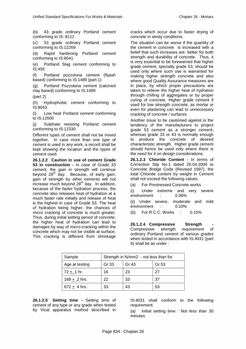
Unified Standard Specifications For Works & Materials Chapter 26 : Mortars
Page 834 : Chapter 26
(b) 43 grade ordinary Portland cement conforming to IS: 8112
(c) 53 grade ordinary Portland cement conforming to IS:12269
(d) Rapid hardening Portland cement conforming to IS:8041
(e) Portland Slag cement conforming to IS:455
(f) Portland pozzolona cement (flyash based) conforming to IS:1489 (part 1)
(g) Portland Pozzolana cement (calcined clay based) conforming to IS:1489
(part 2)
(h) Hydrophobic cement conforming to IS:8043.
(i) Low heat Portland cement conforming to IS:12600
(j) Sulphate resisting Portland cement conforming to IS:12330.
Different types of cement shall not be mixed together. In case more than one type of cement is used in any work, a record shall be kept showing the location and the types of cement used.
26.1.2.2 Caution in use of cement Grade 53 in construction - In case of Grade 33 cement, the gain in strength will continue beyond 28th day. Because, of early gain, gain of strength by other cements will not increase much beyond 28th day. In addition, because of the faster hydration process, the concrete also releases heat of hydration at a much faster rate initially and release of heat is the highest in case of Grade 53. The heat of hydration being higher, the chances of micro cracking of concrete is much greater. Thus, during initial setting period of concrete, the higher heat of hydration can lead to damages by way of micro-cracking within the concrete which may not be visible at surface. This cracking is different from shrinkage
cracks which occur due to faster drying of concrete in windy conditions.
The situation can be worse if the quantity of the cement in concrete is increased with a belief that such increases are better for both strength and durability of concrete. Thus, it is very essential to be forewarned that higher grade cement, specially grade 53, should be used only where such use is warranted for making higher strength concrete and also where good Quality Assurance measures are in place, by which proper precautions are taken to relieve the higher heat of hydration through chilling of aggregates or by proper curing of concrete. Higher grade cement if used for low strength concrete, as mortar or even for plastering can lead to unnecessary cracking of concrete / surfaces.
Another issue to be cautioned against is the tendency of the manufacturers to project grade 53 cement as a stronger cement, whereas grade 33 or 43 is normally enough to produce the concrete of desired characteristic strength. Higher grade cement should hence be used only where there is the need for it on design considerations.
26.1.2.3 Chloride Content - In terms of Correction Slip No.1 dated 26.04.2000 to Concrete Bridge Code (Revised 1997), the total Chloride content by weight in Cement shall not exceed the following values.
(a) For Prestressed Concrete works
(i) Under extreme and very severe environment : 0.06%
(ii) Under severe, moderate and mild environment : 0.10%
(b) For R.C.C. Works : 0.15%
26.1.2.4 Compressive Strength - Compressive strength requirement of ordinary Portland cement of various grades when tested in accordance with IS:4031 (part 6) shall be as under :
Sample Strength in N/mm2 - not less than for
Age at testing Gr.33 Gr.43 Gr.53
72 + 1 hr. 16 23 27
168 + 2 hrs. 22 33 37
672 + 4 hrs. 33 43 53
26.1.2.5 Setting time - Setting time of cement of any type or any grade when tested by Vicat apparatus method described in
IS:4031 shall conform to the following requirement.
(a) Initial setting time : Not less than 30 minutes

Unified Standard Specifications For Works & Materials Chapter 26 : Mortars
Page 835 : Chapter 26
(b) Final setting time: Not more than 600 minutes
26.1.2.6 Supply - The cement shall be packed in jute sacking bags conforming to IS:2580-1982, double hessian bituminised (CRI type) or woven HDPE conforming to IS 11652:1986, woven polypropylene conforming to IS:11653:1986, jute synthetic union conforming to IS:12174:1987, or any other approved composite bags, bearing the manufacturer‟s name or his registered trade mark if any, and grade and type of cement.
Every delivery of cement shall be accompanied by a producer‟s certificate confirming that the supplied cement conforms to relevant specifications. These certificates shall be endorsed to the Engineer for his record.
Every consignment of cement must have identification marks on packages indicating date of manufacture and grade and type of cement. Cement when brought to works shall not be more than 6 weeks old from the date of manufacture. In case due to some reasons it is not possible to use the cement within 3 months then it should be ensured that older lot is used in the lean concrete or other unimportant items of work. Effective precautionary measures shall be taken to eliminate dust nuisance during loading or transferring cement.
26.1.2.7 Stacking and Storage - Cement in bags shall be stored and stacked in a shed which is dry, leak proof and as moisture proof as possible. Flooring of the shed shall consist of the two layers of dry bricks laid on well consolidated earth to avoid contact of cement bags with the floor. Stacking shall be done about 150 to 200mm clear above the floor using wooden planks, old wooden sleepers or scrap GI sheets. Cement bags shall be stacked at least 450mm clear off the walls and in rows of two bags leaving in a space of atleast 600mm between two consecutive rows. In each row the cement bags shall be kept close together so as to reduce air circulation. Stacking shall not be more than 10bags high to avoid lumping under pressure. In stacks more than 8 bags high, the cement bags shall be arranged in header and stretcher fashion, i.e. alternately lengthwise and crosswise so as to tie the stacks together and minimise the danger of toppling over.
A typical arrangement for storing and stacking of cement is shown in Fig.26.1. Different types of cement shall be stacked and stored separately. Cement bags shall be stacked in a manner to facilitate their
removal and use in the order in which they are received.
For extra safety during monsoon, or when cement is expected to be stored for an unusually long period, each stack shall be completely enclosed by a water proofing membrane, such as polythylene/ tarpauline, which shall cover the top of the stack. Care shall be taken to see that the water proofing membrane is not damaged at any time during use. Cement which is set or partially set should on no account be used.
Storage of cement at the work site shall be at the contractor‟s expense and risk. Any damage occurring to cement due to faulty storage in contractor‟s shed or on account of negligence on his part shall be the liability of the contractor.
2.1.2.8 Different types of cements and their properties
(a) 33 Grade Ordinary Portland Cement: IS 269-1989
This ordinary basic Portland cement is in maximum use in the country and is the most suitable cement for all masonry and general concrete works where the members are not to take very high stresses. This cement is not suitable where the member is exposed to sulphates in soil or in ground water.
b. 43 Grade Ordinary Portland Cement: IS 8112-1989 and
c. 53 Grade Ordinary Portland Cement: IS: 12269-1987
Both above types of cements are used where high early strengths in 1 to 28 days range are required. However, the further growth of strength beyond 28 days will be much lower than expected traditionally. These grades of cement are mainly used for RCC works, where a member has to take high tensile stress.
d. Portland Pozzolana Cement: IS: 1489-1991
The pozzolana used in the manufacture of Portland pozzolana cement is burnt clay, shale, or fly ash. The proportion of pozzolana used varies between 10 to 25 per cent by weight of cement as stipulated by Bureau of Indian Standards.
In terms of Correction Slip No.9 dated 27.03.2006 to Concrete Bridge Code (Revised 1997) the use of Portland Pozzolana Cement is subject to the following.
i) “Portland Pozzolana cement shall not be used for PSC Works. When Portland

Unified Standard Specifications For Works & Materials Chapter 26 : Mortars
Page 836 : Chapter 26
Pozzolana Cement is used in plain and reinforced concrete, it is to be ensured that proper damp curing of concrete atleast for 14 days and supporting form work shall not be removed till concrete attains at least 75% of the design strength”.
ii) The rate of development of strength is slow in case of blended cement i.e. Portland Pozzolana cement as compared to ordinary Portland Cement. This aspect should be taken care of while planning to use blended cement. Accordingly stage of prestressing, period of removal of form work and period of curing etc. should be suitably increased.
iii) Compatibility of chemical admixtures and super plasticizers with Portland Pozolana Cement shall be ensured by trials before use.
iv) Some other properties of concrete such as modulus of elasticity, tensile strength, creep and shrinkage are not likely to be significantly different. For design purposes, it will be sufficiently accurate to take the same value as those used for concrete made with OPC.
(d)e. Portland (Blast Furnace) Slag Cement: IS: 455-1989
This type of cement is manufactured by intergrinding the portland cement clinker and blast furnace slag in the proportion of blast furnace slag not exceeding 65% as per Bureau of Indian Standards. The granular slag possesses latent hydraulic properties which are activated when the slag is inter-ground with the portland cement clinker. Portland blast furnace slag cement can be used for all purposes for which ordinary portland cement is used and it can also be used with advantage in mass concrete structures such as retaining walls, foundations and bridge abutments in view of it‟s low heat evolution quality.
In terms of Correction Slip No.9 dated 27.03.2006 to Concrete Bridge Code (Revised 1997) the use of Portland Slag Cement is subject to the following:
i) Mixing of 50% blast furnace slag with OPC cement at site shall not normally be permitted. However, in exceptional cases for bridges requiring higher levels of durability using blended cement which is not available from manufacturers, blending at site may be permitted subject to ensuring dedicated facilities and complete mechanized process control to achieve specified quality with the special permission of Chief Engineer/ Chief Bridge Engineer.
ii) The rate of development of strength is slow in case of blended cement i.e. Portland slag cement, as compared to ordinary Portland Cement. This aspect should be taken care while planning to use blended cement. Accordingly stage of prestressing, period of removal of form work and period of curing etc. should be suitably increased.
iii) Compatibility of chemical admixtures and super plasticizers with Portland blast furnace slag cement shall be ensured by trials before use.
iv) Some other properties of concrete such as modulus of elasticity, tensile strength, creep and shrinkage are not likely to be significantly different. For design purposes, it will be sufficiently accurate to take the same value as those used for concrete made with OPC.
(f)f. Rapid Hardening Portland cement: IS 8041-1990
This cement attains greater strengths at early ages and is hence sometimes called as high early strength cement. This cement at the age of 3 days itself develops the strength developed by ordinary portland cement at the age of 7 days with the same water cement ratio. The use of rapid hardening cement enables the removal of forms early in case of both Precast and Cast-in situ concrete works and hence considerable time and money can be saved. In road works especially where it is imperative to open the road to traffic with minimum delay, the use of this cement will be very much helpful.
(f)g. Hydrophobic Portland Cement: IS 8043-1991
This is cement, which repels water, and can be transported even during rains and stored in humid conditions. While manufacturing the above cement, water repellent chemicals are added during the process of grinding. The chemicals thus added form monomolecular coating over each grain of cement, which prevents water or moisture from air from being readily absorbed by the cement. However, when the cement is mixed with aggregates the above chemical coating gets removed due to abrasion and the hydration takes place exactly in the same way as with ordinary portland cement.
(g)h. Low Heat Portland Cement: IS: 12600-1989
In massive structures such as concrete bridge abutments, retaining walls, etc. when concrete is poured it generates considerable heat due to chemical reaction which takes place while cement is setting and hardening,

Unified Standard Specifications For Works & Materials Chapter 26 : Mortars
Page 837 : Chapter 26
and if the rate at which the heat can be lost from the surface is lower, this will build up extra heat in the structure which is dangerous. Tensile stresses are developed in the concrete when the shrinkage occurs during subsequent curing and thus serious cracks would be developed. In ordinary concrete construction this evolution of heat is of little consequence. Hence, to prevent the above damage low heat portland cement can be profitably used. The low heat cement has better resistance to chemical deterioration than the ordinary portland cement. The rate of development of strength with this cement is much lower than the ordinary portland cement. It is only at the age of 3 months that the strength achieved by the use of both types of cements will be equal.
(h)i. Sulphate resisting Portland Cement: IS: 12330-1988
If the soil contains very high quantity of sulphate it percolates through ground waters. In such areas of alkali conditions, for doing works like canal lining, pipe lines, culverts etc. a cement resistant to sulphate attack of very high degree is required. It is essential to conduct tests to confirm actual values of sulphate concentration, when the structure is located near sea coast, chemical factories, agriculture land using chemical fertilizers and sites where there are effluent discharges or where soluble sulphate bearing ground water level is high. In terms of Correction Slip No.1 dated 26.04.2000 to Concrete Bridge Code (Revised 1997), sulphate resisting cement shall be used only in such conditions where the concrete is exposed to the risk of excessive sulphate attack (eg) concrete in contact with soil or ground water containing excessive amount of sulphate. It shall not be used under such conditions where concrete is exposed to risk of excessive chlorides and sulphate attack both.
j. High Alumina Cement: IS 6452-1989
The main characteristic features of high Alumina cements are they attain high early strength, high heat of hydration and have a good resistance to chemical attack. Initial setting time for high Alumina cement is just 3 minutes when compared to 30 to 45 minutes taken by ordinary portland cement. The final time of setting is just 2 hours after initial setting when compared to about 10 hours taken by ordinary portland cement. Also the high alumina cement attains a strength of 300 kgs/cm2 after one day and 350 kgs/cm2 after 2nd day when compared to the strength achieved by ordinary portland cement as 150 kg/cm2 after one day. Considering the
advantage of high heat of hydration and development of high early strength it can be used in some of the cold regions as a structural material.
(k)k. White Portland Cement: IS:8042-1989
On strength and durability the white cement is as durable and strong as ordinary portland cement, but because of its white colour it is mainly used in interior and exterior decorative works such as external renderings of buildings, facng slabs, terrazzo tiles and floorings, ornamental concrete products, swimming pools, etc.
26.1.3 Fine Aggregate
26.1.3.1 General - Aggregate most of which passes through 4.75mm IS sieve is known as fine aggregate. Fine aggregate shall consist of natural sand, crushed stone sand or crushed gravel sand, stone dust or marble dust, fly ash, Surkhi (crushed brick) or cinder conforming to IS:2686. It shall be hard, durable, chemically inert, clean and free from adherent coatings, organic matter etc. and shall not contain any appreciable amount of clay balls or pellets and harmful impurities e.g. iron pyrites, alkalies, salts, coal, mica, shale or similar laminated materials in such form or in such quantities as to cause corrosion of metal or affect adversely the hardening, the strength, the durability or the appearance of mortar, plaster or concrete. The sum of the percentages of all deleterious material shall not exceed 5%. Fine aggregate must be checked for organic impurities such as decayed vegetation humus, coal dust etc. in accordance with the procedure prescribed in Annexure 26.2. In terms of Correction Slip No.1 dated 26.04.2000 to Indian Railways Concrete Bridge Code (Revised 1997), in general, marine aggregate shall not be used for Reinforced Concrete and Prestressed Concrete works. However in special cases use of marine aggregate may be permitted by the Engineer subject to the following:
a) It shall be thoroughly washed.
b) Generally the limits for Chloride Content and Sulphate content in fine aggregate after washing will be as under – Chloride content. 0.04% by weight acid soluble; Sulphate content 0.40% by weight acid soluble. After washing and drying the aggregate should conform to IS 383.
26.1.3.2 Silt Content - The maximum quantity of silt in sand as determined by the method prescribed in Annexure 26.3 shall not exceed 8%. Fine aggregate containing

Unified Standard Specifications For Works & Materials Chapter 26 : Mortars
Page 838 : Chapter 26
more than allowable percentage of silt shall be washed so as to bring the silt content within allowable limits for which nothing extra shall be paid.
26.1.3.3 Grading - On the basis of particle size, fine aggregate is graded into four zones. The grading when determined in accordance with the procedure prescribed in Annexure 26.4 shall be within the limits given in Table 26.1 below. Where the
grading falls outside the limits of any particular grading zone of sieves, other than 600 micron IS sieve, by a total amount not exceeding 5 per cent, it shall be regarded as falling within that grading zone. The higher the Grading Zone, the finer the sand, with Grading Zone I – coarsest and Grading Zone IV-Finest.
TABLE 26.1
IS Sieve Percentage passing for
Grading Zone I Grading Zone II Grading Zone III Grading Zone IV
10mm 100 100 100 100
4.75 mm 90-100 90-100 90-100 95-100
2.36 mm 60-95 75-100 85-100 95-100
1.18 mm 30-70 55-90 75-100 90-100
600 microns 15-34 35-59 60-79 80-100
300 microns 5-20 8-30 12-40 15-50
150 microns 0-10 0-10 0-10 0-15
Note 1 : For crushed stone sands, the permissible limit on 150 micron sieve is increased to 20 percent. This does not affect the 5 per cent allowance permitted in 26.1.4.3 applying to other sieves.
Note 2 : Allowance of 5% permitted in 26.1.4.3 can be split up, for example, it could be 1% on each of three sieves and 2% on another or 4% on one sieve and 1% on another.
Note 3 : Fine aggregate conforming to Grading Zone IV shall not be used in reinforced cement concrete unless tests have been made to ascertain the suitability of proposed mix proportions.
Note 4 : Sand required for making of mortar for plaster work shall conform to IS:1542-1977 and for masonry work shall conform to IS:2116-1980.
Note 5 : In case marine aggregate is permitted to be used, the grading of fine aggregate should be assessed after thorough washing in water.
26.1.3.4 Type and grading of fine aggregate to be used - These shall be specified in the Contract. It shall be coarse sand, fine sand, stone dust, marble dust, Surkhi or fly ash. Use of sea sand shall not be allowed, unless otherwise specified. Details have been given under items (i) to (iv) below and subparas 26.1.6 and 26.1.7.
(i) Coarse sand shall be either river sand or pit sand or a combination of the two. It shall be clean, sharp, angular, gritty to touch and composed of hard silicious material. Its grading shall fall within the limits of grading Zone I, II, III of Table 26.1. Coarse sand shall have Fineness Modulus not less than 2.5
(ii) Fine sand shall be either river sand or pit sand or a combination of the two. Its grading shall fall within the limits of Grading Zone IV of Table 26.1. Fine sand shall have Fineness Modulus not less than 1.0.
(iii) Stone dust shall be obtained by crushing hard stones or gravel. Its grading shall fall within the limits of Grading Zone I, II or III of Table 26.1.
(iv) Marble dust shall be obtained by crushing marble. Its Grading shall fall within the limits of Grading Zone IV of Table 26.1.
26.1.3.5 Deleterious Material - Sand shall not contain any harmful impurities such as iron, pyrites, alkalis, salts, coal or other organic impurities, mica, shale or similar laminated materials, soft fragments, and sea shale in such form or in such quantities as to affect adversely the hardening, strength or durability of the mortar.
The maximum quantities of clay, fine silt, fine dust and organic impurities in the sand shall not exceed the following limits :

Unified Standard Specifications For Works & Materials Chapter 26 : Mortars
Page 839 : Chapter 26
(1) Clay, fine silt and fine dust when determined
in accordance with IS:2386 (Part II)-1963
in natural sand or crushed gravel sand Not more than 5% by mass
& crushed stone sand
(2) Organic impurities when determined in Colour of the liquid shall be lighter
accordance with IS:2386 (Part II) 1963 than that indicated by the standard
specified in IS:2386 (Part II) 1963.
26.1.3.6 Sand for Masonry Mortar and for Plaster - Sand shall consist of natural sand, crushed stone sand or crushed gravel sand or a combination of any of these. Sand shall be hard, durable, clean and free from adherent coatings and organic matter and shall not contain the amount of clay, silt and
fine dust more than specified under Para 26.1.4.5.
26.1.3.7 Grading of Sand for Masonry Mortar and for Plaster - Grading of sand for use in masonry mortar shall be conforming to IS:2116-1980 (Table 26.2). Grading of sand for use in Plaster shall be conforming to IS:1542-1977 (Table 26.3).
TABLE 26.2
GRADING OF SAND FOR USE IN MASONRY MORTAR AS PER IS : 2116-1980
IS Sieve Designation Percentage passing by mass Ref to method of test
4.75 mm 100 Is: 2386 (Part I) – 1963
2.36 mm 90 to 100
1.18 mm 70 to 100
600 micron 40 to 100
300 micron 5 to 70
150 micron 0 to 15
TABLE 26.3
GRADING OF SAND FOR USE IN PLASTER AS PER IS 1542- 1977
IS Sieve Designation Percentage passing
10mm 100
4.75 mm 95 to 100
2.36 mm 95 to 100
1.18 mm 90 to 100
600 micron 80 to 100
300 micron 20 to 65
150 micron 0-50
Note:- For crushed stone sands, the permissible limit on 150 micron IS Sieve is increased to 20%. This does not affect the 5% allowance under IS:2386 (Part I-1963) also indicated in Para 26.1.4.3 above.
26.1.3.8 Bulking - Fine aggregate, when dry or saturated, has almost the same volume but dampness causes increase in volume. In case fine aggregate is damp at the time of proportioning the ingredients for
mortar or concrete, its quantity shall be increased suitably to allow for bulkage, which shall be determined by the method prescribed in Annexure 26.5. Table 26.4 gives the relation between moisture content

Unified Standard Specifications For Works & Materials Chapter 26 : Mortars
Page 840 : Chapter 26
and percentage of bulking for guidance only. Bulkage % age may be assessed on prorata basis for the different %age of moisture content present at the time of using the fine
aggregate or while making payments at the time of measuring the same in case of supply of materials.
TABLE 26.4
Moisture content %age Bulking %age (by volume)
1 8
2 15
3 20
4 25
5 30
26.1.3.9 Prior approval and Stacking - The sand shall be got approved by the Engineer before use and sand which is rejected should be immediately removed from site of work. Fine aggregate shall be so stacked as to prevent dust and foreign matter getting mixed up with it, as far as practically possible.
26.1.3.10 Measurements - As the fine aggregate bulks to a substantial extent when partially wet, measurements shall be taken when the stacks are dry or appropriate allowance made for bulking.
2.1.5 Surkhi - Broken Brick (Burnt Clay) Fine Aggregate
2.1.5.1 General
Broken Brick (Burnt Clay) Fine aggregate, also known as Surkhi, shall be made by grinding well burnt (but not under or over burnt) broken bricks as specified in IS:3068-1986. It shall not contain any harmful impurities, such as iron pyrites, salts, coal, mica, shale or similar laminated or other materials in such form or quantity as to adversely affect hardening, strength, durability or appearance of the mortar. The maximum quantities of clay, fine silt, fine dust and organic impurities in surkhi (all taken together) shall not exceed five per cent by weight. The particle size grading of surkhi for use in lime mortars shall be within the limits specified in Table 26.5. Surkhi shall not be used in situations where there is much salt in the soil.
TABLE 26.5
IS Sieve Designation Percentage passing (by wt)
4.75 mm 100
2.36 mm 90-100
1.18 mm 70-100
600 microns 40-100
300 microns 5-70
150 microns 0-15
26.1.4.2 Stacking
Surkhi shall be stacked on a hard surface or platform so as to prevent the admixture of clay, dust, vegetation and other foreign matter. It shall be also protected from rain and dampness and kept under adequate coverings.
26.1.4.3 Measurements
For the purposes of payment. Surkhi shall be measured in regular stacks in cubic metres.
Alternatively it may be measured by weight when supplied in bags. If volumetric measurements are done, 12.50% deduction shall be made towards shrinkage from the gross stack volume.
26.1.5 FLY ASH
2.1.6.1 General
Fly ash is a finely divided residue resulting from the combustion of pulverised coal in boilers. Fly ash used shall be as per

Unified Standard Specifications For Works & Materials Chapter 26 : Mortars
Page 841 : Chapter 26
IS:3812-1981. It shall be clean and free from any contamination of bottom ash, grit or small pieces of pebbles. Fly ash is meant for use as a part replacement of fine aggregate
in mortar with a view to improve grading and to make use of its pozzolanic properties.
Fly ash shall be supplied in the following grades corresponding to the properties specified in Annexure 26.6.
Grade Designation General use
Grade I For incorporation in cement mortar and concrete and in lime pozzolana mixtures, and for manufacture of portland pozzolana cement.
Grade II For incorporation in cement mortar and concrete and lime pozzolana mixture
Note : It is obligatory on the part of supplier/ manufacture to ensure that the fly ash conforms to the requirement mutually agreed upon & shall furnish a certificate to this effect to the purchaser or his representative.
26.1.5.2 Characteristics
The chemical and physical requirements of fly ash shall be as specified in Annexure 26.6.
2.1.6.3 Stacking
Fly ash shall be protected from dirt collecting on it.
26.1.5.4 Measurements: For the purposes of payment Fly ash shall be measured in regular stacks in cubic metres. Alternatively it may also be measured by weight when supplied in bags. If volumetric measurements are done, the extent of shrinkage should be assessed in advance and provided for in the Supply Contract.
26.2 PREPARATION OF MORTARS AND THEIR GRADES AND THEIR APPLICATION IN WORKS
26.2.1 Grade of Masonry Mortar
The grade of masonry mortar will be defined by its compressive strength in N/ mm2 at the age of 28 days as determined by the standard procedure detailed in IS:2250-1981.
For details of grades and criteria for selection of masonry mortar, see Annexure 26.7. This Annexure is based on Appendix G in CPWD Specifications 1996 updated upto July 2000.
26.2.1.1 Proportioning of the ingredients
For proportioning the ingredients by volume, the conversion of weight into volume shall be made on the following basis:
(a) Dry hydrated lime 700 kg/cum
(b) Burnt clay pozzolana 860 kg/cum
(c) Lime Pozzolana mixture 770 kg/cum
(d) Coarse Sand (dry) 1280 kg/cum
(e) Fine sand (dry) 1600 kg/cum
(f) Fly Ash 590 kg/cum
One cum of lime putty shall be taken as equivalent to 0.70 Cum. of dry hydrated lime.
26.2.1.2 Classification of Mortars
Mortar strength in general shall not be greater than that of masonry units, nor greater than necessary in any application. The mortar can be broadly classified into Cement mortar, lime mortar and cement-lime mortar. The main characteristics are as under:
a) Cement Mortars
These consist of cement and sand, varying in proportions from 1:8 to 1:3, the strength and workability improving with the increase in proportion of cement.
Mortars richer than 1:3 are not used in masonry because of high shrinkage and no appreciable gain in the strength of masonry.
Mortars leaner than 1:5 tend to become harsh and unworkable.
26.2.1.3 Selection of Mortar for use in Railway Works - Cement Mortar
The mix proportions shall be as specified for each particular class of work as indicated in the Drawings. Under normal conditions, unless otherwise specified, the proportions of cement to sand (by volume) for the different classes of work shall be as under :
i) Ordinary brick work and masonry 1:5 or 1:6
ii) Heavily loaded walls and pillars / Bridge Masonry 1:3 or 1:4

Unified Standard Specifications For Works & Materials Chapter 26 : Mortars
Page 842 : Chapter 26
iii) Walls half brick thick, jack arches and bridge structure other than arches 1:4
iv) Arches other than jack arch 1:3 or 1:4
v) Plaster for buildings (inside) 1:6
vi) Plaster for buildings (outside) 1:4
vii) Pointing 1:3
In measuring damp sand, allowance shall be made for bulkage as indicated in Para 26.1.4.8.
26.3 Cement Mortar – Preparation and time limit for use
26.3.1 General
This shall be prepared by mixing cement and sand with or without the addition of pozzolana in specified proportions as per Annexure 26.7. In terms of provisions in Indian Railways Concrete Bridge Code (Revised 1997), the Engineer may permit the use of admixture for imparting special characteristics to the mortar on satisfactory evidence that the use of such admixtures does not adversely affect the proportion of Mortar, particularly with regard to strength, volume change and durability.
26.3.2 Proportioning
Cement bag weighing 50 kg shall be taken as 0.035 cubic metre. Other ingredients in specified proportion shall be measured using preferably boxes of size 40 x 35 x 25 cm for machine mixing by volume. Sand shall be measured on the basis of its dry volume. In case it is moist then proper allowance for bulkage should be made.
26.3.3 Mixing
The mixing of mortar shall be done in mechanical mixers operated manually or by power as decided by the Engineer. The Engineer may, however, permit hand mixing at his discretion taking into account the nature, magnitude and location of the work and practicability of the use of mechanical mixers or where item involving small quantities are to be done or if in his opinion the use of mechanical mixer is not feasible. In cases, where mechanical mixers are not to be used, the contractor shall take permission of the Engineer in writing before commencement of the work.
(a) Mechanical Mixing : Cement and sand in the specified proportions shall be mixed dry thoroughly in a mixer. Water shall then be added gradually and wet mixing continued for at least three minutes. Only the required quantity of water shall be added which will produce mortar of workable consistency but not stiff paste. Only the quantity of mortar, which can be used within
30 minutes of its mixing shall be prepared at a time. Mixer shall be cleaned with water each time before suspending the work.
(b) Hand Mixing:- The measured quantity of sand shall be levelled on a clean masonry platform and cement bags emptied on top. The cement and sand shall be thoroughly mixed dry by being turned over and over, backwards and forwards, several times till the mixture is of a uniform colour. The quantity of dry mix which can be used within 30 minutes shall then be mixed in a masonry trough with just sufficient quantity of water to bring the mortar to a stiff paste of necessary working consistency, which will permit to be applied without separation of water or segregation of the solid material of the mix.
26.3.4 Precautions
Mortar shall be used as soon as possible after mixing and before it begins to set, and in any case within half hour, after the water is added to the dry mixture.
26.4 Cement Flyash Sand Mortar – Preparation and Time limit for use
2.2.5.1 General:
This shall be prepared by mixing cement, flyash fly ash and sand in specified proportions as per Annexure 26.7. Mixing shall be done in a mechanical mixer (operated manually or by power) unless otherwise permitted by the Engineer in writing.
26.4.2 Proportioning
Cement bag weighing 50 kg shall be taken as 0.035 cubic metre. Other ingredients in the specified proportions shall be measured using boxes of suitable sizes. Sand and flyash shall be measured on the basis of their dry volume.
26.4.3 Mixing
(a) Mechanical Mixing: Sand and flyash in the specified proportions shall be mixed dry in a mixer and then the specified quantity of cement shall be added and mixed dry thoroughly. Water shall then be added

Unified Standard Specifications For Works & Materials Chapter 26 : Mortars
Page 843 : Chapter 26
gradually and wet mixing continued for atleast one minute. Water shall be just sufficient to bring the mortar to the consistency of a workable paste. Only the quantity of mortar which can be used within 30 minutes of its mixing, shall be prepared at a time.
(b) Hand Mixing: The measured quantity of sand and flyash shall be mixed dry on a clean masonry platform before adding specified quantity of cement to it. The resulting mixture of cement, sand and flyash shall then be mixed thoroughly being turned over and over, backward several times till the mixture is of a uniform colour. The quantity of dry mix which can be used within 30 minutes shall then be mixed in a clean watertight masonry trough with just sufficient quantity of water, to bring the mortar to a stiff paste of necessary working consistency, which will permit supplying it without separation of water or segregation of the solid materials of the mix.
26.4.4 Precautions
Shall be same as specified in 26.3.4.
26.5 Consistency of Masonry Mortar
26.5.1 General
The working consistency of the mortar is a matter of judgement. The water should be enough to maintain workability of the mortar during application but at the same time it shall not be excessive leading to segregation. The quantity of water needed for maintaining consistency or workability will also depend on the masonry for which the mortar is used e.g., thinner joints require greater workability whereas bed joints subject to heavy pressure will require stiffer mortar. Also the mortar should be able to hold the water against absorption by the masonry.
26.5.2 Measurement of consistency
A simple field test for consistency can be carried out by means of a cone penetration apparatus as given in Appendix B of IS: 1625. For various situations of use of
masonry mortar the following values for depth of penetration as measured by the Standard Cone Apparatus are recommended. Specific details have been given under the relevant Chapters on Brick Masonry, Stone Masonry and on Finishing Works including Pointing and Plastering.
i) For laying walls of solid bricks 9-13 cm
ii) For laying perforated bricks 7-8 cm
iii) For filling cavities 13-15 cm
iv) For pointing and plastering 3-4 cm
26.6 Time Limit in Use of Mortar
Special care should be exercised in ensuring that the mortars of different classes are used within the time limits specified in Paras 26.26.2.5, 26.2.3.4, 26.2.4.4. and 26.2.5.4. Mortar remaining unused beyond these periods shall be rejected and removed from site of work.
26.7 Curing of Masonry Works
26.7.1 Curing Period
All masonry using cement mortars, shall be kept wet for a period of seven days after construction.
26.7.2 General
In the case of masonry works in lime mortars, it is desirable that the work, after a height of every 1.5m or less shall be allowed to set for atleast two days before starting further construction over it.
26.8 Strength Development of Masonry Mortar
26.8.1 General
Strength Development is an important requirement before masonry is loaded to the full extent and the rate of construction should synchronize with the development of the strength of masonry particularly in the case of masonry with weak mortars. The following guidance with regard to the strength development of cement mortar and cement lime mortars will be found useful :l
Age of mortar in days 3 7 14 28 60 90
Relative strength of mortars
as percentage of 28 days strength 25 50 75 100 120 130
26.8.2 Masonry work at low temperature
Extra time shall be allowed for hardening of mortar when the atmospheric temperature
during construction is very low. Period will have to be increased by 100% for the time during which the temperature remains below

Unified Standard Specifications For Works & Materials Chapter 26 : Mortars
Page 844 : Chapter 26
5 deg. C and by 50% for the time when temperature is between 5 deg. and 10 deg.C.
ANNEXURE 26.1
BUILDING LIME PHYSICAL REQUIREMENTS
SL Characteristics Class Method or Test, Ref.to
A B C D E
Hyd-rated
Quick Hyd-rated
Quick Hyd-rated
Quick Hyd-rated
Hyd-rated
(1) (2) (3) (4) (5) (6) (7) (8) (9) (10) (11)
I (i) Fineness:
(a) Residue on
2.36mm IS Sieve, percent, Max.
Nil -- Nil _ Nil -- Nil Nil IS:6932 (Part 4)- 1973*
(b)Residue on 300 micron IS Sieve, percent, Max.
5 -- 5 -- Nil -- Nil 5
(c) Residue on 212 micron IS Sieve, percent, Max.
-- -- -- -- 10 -- 10 --
(ii) Residue on slaking:
(a) Residue on 850 micron IS Sieve, percent Max
-- 10 -- 5 -- 5 -- -- IS:6932 (Part 3)- 1973 **
(b) Residue on 300 micron IS Sieve, percent Max
-- -- -- 5 -- 5 -- --
(iii)
Setting time:
(a) Initial Set, Min, h,
2 --
--
--
--
--
--
2 IS:6932 (Part II)- 1984 ***
(b) Final Set, Max. h
48 --
--
--
--
--
--
48
(iv) Compressive strength, Min. N/mm2
(a) at 14 days
1.75 1.25 1.25 --
--
--
--
1.0 IS:6932 (Part 7)
(b) at 28 days 2.8 1.75 1.75 --
--
--
--
1.75 1973#
(v) Transverse strength at 28 days, N/mm2, Min
1.0 0.7 0.7 -- -- -- -- 0.7 IS:6932 (Part 7)- 1973#
(vi) Workability bumps, Max
-- -- -- 12 10 12 10 -- IS: 6932 (Part 8)- 1973##

Unified Standard Specifications For Works & Materials Chapter 26 : Mortars
Page 845 : Chapter 26
(vii) Volume yield ml/g, Min
-- -- -- 1.7 -- 1.4 -- -- IS:6932 (Part 6)- 1973###
(viii) Soundness, Le Chaterlier expansion mm, Max
5 -- 5 -- -- -- -- 10 IS:6932 (Part 9)- 1973$
(ix) Popping & pitting Free from pop and pits
-- Free from pop and pits
_ Free from pop and pits
- Free from pop and pits
- IS:6932 (Part-10) 1973$$
* Methods of tests for building limes : Part 4 Determination of fineness of hyderated lime
** Methods of tests for building limes : Part 3 Determination of residue on slaking of quicklime.
*** Methods of tests for building limes : Part 11 Determination of setting time of hydrated lime.
# Methods of tests for building limes : Part 7 Determination of compressive and transverse strengths
## Methods of tests for building limes : Part 8 Determination of workability
### Methods of tests for building limes : Part 6 Determination of volume yield of quicklime
$ Methods of tests for building limes : Part 9 Determination of soundness
$ Methods of tests for building limes : Part 10 Determination of popping and pitting of hyderated lime
Unified Standard Specifications For Works & Materials Chapter 26 : Mortars
Page 846 : Chapter 26
ANNEXURE 26.2
FINE AGGREGATES
TEST FOR ORGANIC IMPURITIES
The aggregate must also be checked for organic impurities such as decayed vegetation humus, coal dust etc.
What is called the colour test is reliable indicator of the presence of harmful organic matter in aggregate, except in the area where there are deposits of lignite.
Fill a 350 ml clear glass medicine bottle upto 70 ml mark with a 3% solution of caustic soda or sodium hydroxide. The sand is next added gradually until the volume measured by the sandy layer is 125 ml. The volume is then made upto 200 ml by addition of more of solution. The bottle is then stoppered and shaken vigorously and allowed to stand for 24 hours. At the end of this period, the colour of the liquid will indicate whether the sand contains a dangerous amount of matter. A colourless liquid indicates a clean
sand free from organic matter. A straw coloured solution indicates some organic matter but not enough to be seriously objectionable. Darker colour means that the sand contains injurious amounts and should not be used unless it is washed, and a retest shows that it is satisfactory.
Add 2.5 ml of two per cent solution of tannic acid in 10 per cent alcohol, to 97.5 ml of three per cent -- hydroxide solution. Place in a 350 ml bottle, fix the stopper, shake vigorously and allow to stand for 24 hours before comparison with the solution above the sand.
Note: A three per cent solution of caustic soda is made by dissolving 3 g of sodium hydroxide in 100 ml of water, preferably distilled. The solution should be kept in a glass of bottle tightly closed with a rubber stopper. Handling sodium hydroxide with moist hands may result in serious burns. Care should be taken not to spill the solution for it is highly injurious to clothing, leather, and other materials.
ANNEXURE 26.3
TEST FOR SILT CONTENT IN SAND
The sand shall not contain more than 8% of silt as determined by field test with measuring cylinder. The method of determining silt contents by field test is given below :
A sample of sand to be tested shall be placed without drying in a 200ml measuring cylinder. The volume of the sample shall be such that it fills the cylinder upto 100ml mark.
Clean water shall be added upto 150 ml mark. Dissolve a little salt in the water in the proportion one tea spoon to half a litre. The mixture shall be shaken vigorously, the last few shakes being sidewise direction to level off the sand and the contents allowed to settle for three hours.
The height of the silt visible as settled layer above the sand shall be expressed as a percentage of the height of sand below. The sand containing more than the above allowable percentage of silt, shall be washed so as to bring the silt contents within allowable limits.
ANNEXURE 26.4
GRADING OF FINE AGGREGATE
TEST FOR PARTICLE SIZE (SIEVE ANALYSIS)
Apparatus: Perforated plate sieves of designation 10mm, 4.75mm and fine mesh
sieve of designation 2.36mm, 1.18 mm, 600 micron, 300 micron and 150 micron should be used.
The balance or scale shall be such that it is readable and accurate to 0.1 percent of the weight of the test sample.
Sample: The weight of sample available shall not be less than the weight given in the table below. The sample of sieving shall be

Unified Standard Specifications For Works & Materials Chapter 26 : Mortars
Page 847 : Chapter 26
prepared from the larger sample either by quartering or by means of a sample divider.
TABLE SHOWING MINIMUM WEIGHTS FOR SAMPLING
Maximum size present in substantial proportions (mm)
Minimum weight of sample for sieving (kg)
10 0.5
4.75 0.2
2.36 0.1
Test Procedure
The sample shall be brought to an air-dry condition before weighing and sieving. This may be achieved either by drying at room temperature or by heating at a temperature of 100 degree to 110 degree centigrade. The air dry sample shall be weighed and sieved successively on the appropriate sieves starting with the largest. Care shall be taken to ensure that the sieves are clean before use.
Each sieve shall be shaken separately over a clean tray until not more than a trace passes, but in any case for a period of not less than two minutes. The shaking shall be done with a varied motion, backwards and forwards, left to right, circular clockwise and anti-clockwise, and with frequent jarring, so that the material is kept moving over the sieve surface in frequently changing directions. Materials shall not be forced through the sieve by hand pressure, but on sieves coarser than 20mm, placing of particles is permitted. Lumps of fine material, if present may be broken by gentle pressure with fingers against the side of the sieve. Light brushing of under side of the sieve with a soft
brush may be used to clear the sieve openings.
Light brushing with a fine camel hair brush may be used on the 150 micron IS sieve to prevent segregation of powder and blinding of apertures. Stiff or worn out brushes shall not be used for this purpose and pressure shall not be applied to the surface of the sieve to force particles through the mesh.
On completion of sieving the material retained on each sieve, together with any material cleaned from the mesh, shall be weighed.
Reporting of Results
The results shall be calculated and reported as :
(a) The cumulative percentage by weight of the total sample passing each of the sieves, to the nearest whole number. or
(b) The percentage by weight of the total sample passing one sieve and retained on the next smaller sieve, to the nearest 0.1 percent.
ANNEXURE 26.5
BULKING OF FINE AGGREGATES / SAND (FIELD METHODS)
Two methods are suggested for determining the bulking of sand / fine aggregate. The procedure may be suitably varied, if necessary. Both depend on the fact that the volume of inundated sand / fine aggregate is the same if the sand/ fine aggregate were dry.
Method 1: Put sufficient quantity of wet sand loosely into a container until it is about two-third full. Level off the top of the sand and push a steel rule vertically down through the sand at the middle to bottom, measure the height. Suppose this is „X‟ cm.
Empty the sand out of the container into another container where none of it is lost. Half fill the first container with water. Put back about half the sand and rod it with a steel rod, about 6mm in diameter, so that its volume is reduced to a minimum. Then add the remainder and level the top surface of the inundated sand. Measure its depth at the

Unified Standard Specifications For Works & Materials Chapter 26 : Mortars
Page 848 : Chapter 26
middle with the steel rule. Suppose this is „Y‟ cm.
The percentage of bulking of the sand due to moisture shall be calculated from the formula:
Percentage bulking (X/Y-1) x 100
Method 2: In a 250 ml measuring cylinder, pour the damp sand, consolidate it by stacking until it reaches the 200 ml mark.
Then fill the cylinder with the water and stir the sand well (the water shall be sufficient to submerge the sand completely). It will be seen that the sand surface is now below its original level. Suppose the surface is at the mark of Y ml. The percentage of bulking of sand due to moisture shall be calculated from the formula.
Percentage bulking = (200/Y-1) x 100
ANNEXURE 26.6
FLY ASH : PHYSICAL REQUIREMENTS
SL Characteristic Requirement Grade of Fly Ash
I II
(1) (2) (3) (4)
(i) Fineness – Specific surface in m2 / kg by Blaine‟s permeability method, Min
320 250
(ii) Lime reactivity – average compressive strength in N/mm2 Min 4.0 3.0
(iii) Compressive strength at 28 days in N/mm2 Not less than 80 percent of the strength of corresponding plain cement mortar cubes
(iv) Drying Shrinkage, per cent, Max 0.15 0.10
(v) Soundness of autoclave test expansion of specimens, per cent, Max 0.8 0.8
CHEMICAL REQUIREMENTS
SL Characteristic Requirement
(1) (2) (3)
(i) Silicon dioxide (SiO2) plus aluminium oxide (Al2 O3) plus iron oxide (Fe2 O3) per cent by mass, Min
70.00
(ii) Silicon dioxide (SiO2)per cent by mass Min 35.0
(iii) Magnesium Oxide (MGO) per cent by mass Max 5.0
(iv) Total sulphur as sulphur trioxide (SO3) per cent by mass, Max 2.75
(v) Available alkalis as sodium oxide (Na2)) per cent by mass, Max (see Note 1)
1.50
(vi) Loss of ignition, percent by mass, Max 12.0
Note 1 : Applicable only when reactive aggregates are used in concrete and are specially requested by the purchaser.
Note 2 : For determination of available alkalis IS: 4032-1985 “Method of chemical analysis of hydraulic cement‟ shall be referred to.

Unified Standard Specifications For Works & Materials Chapter 26 : Mortars
Page 849 : Chapter 26
ANNEXURE 26.7
CRITERIA FOR SELECTION OF MASONRY MORTARS
(a) The selection of masonry mortars from durability consideration will have to cover both the loading and exposure conditions of the masonry. The masonry mortar shall generally be as specified in (b) to (g).
(b) In case of masonry exposed frequently to rain and where there is further protection by way of plastering or rendering or other finishes, the grade of mortar shall not be less than MM 0.7 but shall preferably be of grade MM2. Where no protection is provided, the grade of mortar for external walls shall not be less than MM2.
(c) In case of load bearing internal walls, the grade of mortar shall preferably be MM 0.7 or more for high durability but in no case less than MM 0.5.
(d) In the case of masonry work in foundations laid below damp proof course, the grade of mortar for use in masonry shall be as specified below:
(i) Where soil has little moisture, masonry mortar of grade not less than MM 0.7 shall be used.
(ii) Where soil is very damp, masonry mortar of grade preferably MM2 or more shall be used. But in no case shall the grade of mortar be less than MM2.
(e) For masonry in building subject to vibration of machinery, the grade of mortar shall not be less than MM 3.
(f) For parapets, where the height is greater than thrice the thickness, the grade of masonry mortar shall not be less than MM3. In case of low parapets the grade of mortar shall be the same as used in the wall masonry.
(g) The grade of mortar for bedding joints in masonry with large concrete blocks shall not be less than MM3.

Unified Standard Specifications For Works & Materials Chapter 26 : Mortars
Page 850 : Chapter 26
GRADE OF MASONRY MORTARS
SL Grade Mortar Mix (By Loose Volume) Compressive
Strength At 28 days
Cement Lime Pozzolana Sand
(1) (2) (3) (4) (5) (6) (7)
1 MM 0-5 0 1 B or E 0 3 0.5 to 0.7
2 0 1 C or D 1 2
3 MM 0-7 1 3 C or D 0 12 0.7 to 1.5
4 1 0 0 8
5 1 0 0.4 10
6 MM 1.5 1 0 0 7 1.5 to 2
7 1 0 0.4 8.75
8 0 1A 0 3
9 MM 2 0 1A 0 2 2 to 3
10 0 1C or D 3 0
11 1 2C or D 0 9
12 MM 3 0 1C or D 2 0 3 to 5
13 1 1C or D 0 0
14 1 0 0 6
15 0 1A 0 1
16 1 0 0.21 4.2
17 1 0 0.4 7.5
18 MM 5 1 0 To 1/4B,C,D
OR E
0 4 5 to 7.5
19 1 0 0 5
20 1 0 0.4 6.25
21 1 0 0.4 5
22 MM 7.5 1 „1/4 C or D 0 3 7.5 and above
23 1 „1/2 C or D 0 4.5
24 1 0 0 4
25 1 0 0.2 2.1
26 1 0 0 3
27 1 0 0.4 3.75
Note :
1) A,B,C,D and E denote the classes of limes to be used (see IS:712-1984 specification for building limes) (refer Para 26.1.3.1)
2) The strength values of lime mortar given in the table are after wet grinding of the mortar ingredients.
3) The compressive strength shall be determined in accordance with the procedure given in IS 2250-1981.

Unified Standard Specifications For Works & Materials Chapter 26 : Mortars
Page 851 : Chapter 26
4) Pozzolana to be of minimum lime reactivity of 4N/MM2
5) When using plain Cement Mortar, it is desirable to include a plasticizer in the mix to improve workability. If sand used is too coarse and graded.
6) Strength of mortar may vary appreciably, depending on angularity grading and fineness of sand. Quantity of sand in the mix may therefore be varied where found necessary to attain the desired strength.
7) Other mortar mixes may also be permitted where necessary as in block work.
LIST OF RECOMMENDED TESTS ON MATERIALS
Material
Para Test Field / Laborat
ory
Test Procedure
Minimum
quantity of
Material for
carrying out test
Frequency of testing
Water 26.1.1 i) pH Value
ii) Limits of Acidity
iii) Limits of Alkalinity
iv) Percentage of solids
(a) Chlorides
(b) Suspended matter
(c) Sulphates
(d) Inorganic solids
(e) Organic solids
Lab
”
”
”
IS:3025 Water from each source shall be got tested before the commencement of work and thereafter once in every three months till the completion of the work. Water from municipal source need be tested only once in six months. Number of Tests for each source shall be 3.
Cement
26.1.2 Physical Requirement
(i) Fineness
(ii) Soundness
(iii) Setting time (Initial & Final)
(iv) Compressive Strength
(v) Consistency of standard cement paste
Lab
”
”
”
”
”
(i) IS:4031 (Part II)
(ii) IS:4031 (Part III)
(iii) IS:4031 (Part V)
(iv) IS: 4031 (Part VI)
Each lot Every 50 tonnes or part thereof
Lime 26.1.3 Chemical and physical properties of lime
Lab Physical Properties (I to
IX) of
Annexure 26.1 (IS 6932)
Chemical properties
(I to VI) Annexure 26.1
(IS 6932)
(VII & VIII) of Annexure 26.1
(IS 1514)
5MT 10 MT or part thereof as desired by Engineer

Unified Standard Specifications For Works & Materials Chapter 26 : Mortars
Page 852 : Chapter 26
Sand 26.1.4.1 Organic impurities Field Annexure 26.2 20 cum Every 20 cum or part thereof or more frequently as decided by the Engineer
26.1.4.2 Silt content Field Annexure 26.3 20 cum -do-
26.1.4.4 Particle size distribution a, b, c, d & e
Field or Lab as decided by the
Engineer
Annexure 26.4 40 cum 40 cum or part thereof
26.1.4.8 Bulking of sand Field Annexure 26.5 20 cum Every 20 cum or part thereof or more frequently as decided by the Engineer.
FIGURE 26.1TYPICAL SKETCH FOR CEMENT GODOWN
SECTION
A.C. OR G.I. SHEET
MOBILE ROLLER PAN MIXER (HEAVY DUTY LIME MORTAR MILL)(Para 2.2.2.4)
FIGURE 26.2
OR ANY KIND OFWEATHER PROOF ROOF
LOAD BEARINGWALL
(MAX.10 BAGS)
PLANKS
150 DRY BRICKS INTWO LAYERS
150 CONSOLIDATED EARTH
1400
2400
G
1400
WOODEN BATTENS
DOOR PLAN
450600 1400
450
PA
SS
AG
E