
CHAPTER 21 MAGNETIC FORCES AND MAGNETIC …Chapter 21 Problems 1079 CHAPTER 21 MAGNETIC FORCES AND...
53
CHAPTER 21 MAGNETIC FORCES AND MAGNETIC FIELDS ANSWERS TO FOCUS ON CONCEPTS QUESTIONS ____________________________________________________________________________________________ 1. (d) Right-Hand Rule No. 1 gives the direction of the magnetic force as x for both drawings A and B. In drawing C, the velocity is parallel to the magnetic field, so the magnetic force is zero. 2. (b) Using Right-Hand Rule No. 1 (see Section 21.2), we find that the direction of the magnetic force on a positively charged particle is to the west. Reversing this direction because the particle is a negative electron, we see that the magnetic force acting on it points to the east. 3. (a) Using Right-Hand Rule No. 1 (see Section 21.2), we find that the direction of the magnetic force on a positively charged particle is straight down toward the bottom of the screen. 4. B = 1.1 10 1 T, south 5. (c) The electric force points out of the screen, in the direction of the electric field. An application of Right-Hand Rule No. 1 shows that the magnetic force also points out of the screen, parallel to the electric force. When two forces have the same direction, the magnitude of their sum has the largest possible value. 6. (e) In this situation, the centripetal force, F c = mv 2 /r (Equation 5.3), is provided by the magnetic force, F = qvB sin 90.0 (Equation 21.1), so mv 2 /r = qvB sin 90.0. Thus, / q mv rB , and the charge magnitude q is inversely proportional to the radius r. Since the radius of curve 1 is smaller than that of curve 2, and the radius of curve 2 is smaller than that of curve 3, we conclude that q 1 is larger than q 2 , which is larger than q 3 . 7. (a) The magnetic force that acts on the electron in regions 1 and 2 is always perpendicular to its path, so the force does no work. According to the work-energy theorem, Equation 6.3, the kinetic energy, and hence speed, of the electron does not change when no work is done. 8. (d) According to Equation 21.2, the radius r of the circular path is given by / r mv qB . Since v, q, and B are the same for the proton and the electron, the more-massive proton travels on the circle with the greater radius. The centripetal force F c acting on the proton must point toward the center of the circle. In this case, the centripetal force is provided by the magnetic force F. According to Right-Hand Rule No. 1, the direction of F is related to the velocity v and the magnetic field B. An application of this rule shows that the proton
Transcript of CHAPTER 21 MAGNETIC FORCES AND MAGNETIC …Chapter 21 Problems 1079 CHAPTER 21 MAGNETIC FORCES AND...

CHAPTER 21 MAGNETIC FORCES AND
MAGNETIC FIELDS
ANSWERS TO FOCUS ON CONCEPTS QUESTIONS ____________________________________________________________________________________________
1. (d) Right-Hand Rule No. 1 gives the direction of the magnetic force as x for both drawings
A and B. In drawing C, the velocity is parallel to the magnetic field, so the magnetic force is
zero.
2. (b) Using Right-Hand Rule No. 1 (see Section 21.2), we find that the direction of the
magnetic force on a positively charged particle is to the west. Reversing this direction
because the particle is a negative electron, we see that the magnetic force acting on it points
to the east.
3. (a) Using Right-Hand Rule No. 1 (see Section 21.2), we find that the direction of the
magnetic force on a positively charged particle is straight down toward the bottom of the
screen.
4. B = 1.1 101 T, south
5. (c) The electric force points out of the screen, in the direction of the electric field. An
application of Right-Hand Rule No. 1 shows that the magnetic force also points out of the
screen, parallel to the electric force. When two forces have the same direction, the
magnitude of their sum has the largest possible value.
6. (e) In this situation, the centripetal force, Fc = mv2/r (Equation 5.3), is provided by the
magnetic force, F = qvB sin 90.0 (Equation 21.1), so mv2/r = qvB sin 90.0. Thus,
/q mv rB , and the charge magnitude q is inversely proportional to the radius r. Since the
radius of curve 1 is smaller than that of curve 2, and the radius of curve 2 is smaller than
that of curve 3, we conclude that q1 is larger than q2, which is larger than q3.
7. (a) The magnetic force that acts on the electron in regions 1 and 2 is always perpendicular
to its path, so the force does no work. According to the work-energy theorem, Equation 6.3,
the kinetic energy, and hence speed, of the electron does not change when no work is done.
8. (d) According to Equation 21.2, the radius r of the circular path is given by /r mv qB .
Since v, q, and B are the same for the proton and the electron, the more-massive proton
travels on the circle with the greater radius. The centripetal force Fc acting on the proton
must point toward the center of the circle. In this case, the centripetal force is provided by
the magnetic force F. According to Right-Hand Rule No. 1, the direction of F is related to
the velocity v and the magnetic field B. An application of this rule shows that the proton

Chapter 21 Answers to Focus on Concepts Questions 1077
must travel counterclockwise around the circle in order that the magnetic force point toward
the center of the circle.
9. rproton/relectron = 1835
10. (c) When, for example, a particle moves perpendicular to a magnetic field, the field exerts a
force that causes the particle to move on a circular path. Any object moving on a circular
path experiences a centripetal acceleration.
11. F = 3.0 N, along the y axis
12. (e) The magnetic field is directed from the north pole to the south pole (Section 21.1).
According to Right-Hand Rule No. 1 (Section 21.5), the magnetic force in drawing 1 points
north.
13. (c) There is no net force. No force is exerted on the top and bottom wires, because the
current is either in the same or opposite direction as the magnetic field. According to Right-
Hand Rule No. 1 (Section 21.5), the left side of the loop experiences a force that is directed
into the screen, and the right side experiences a force that is directed out of the screen
(toward the reader). The two forces have the same magnitude, so the net force is zero. The
two forces on the left and right sides, however, do exert a net torque on the loop with respect
to the axis.
14. (d) According to Right-Hand Rule No. 1 (Section 21.5), all four sides of the loop are
subject to forces that are directed perpendicularly toward the opposite side of the square. In
addition, the forces have the same magnitude, so the net force is zero. A torque consists of a
force and a lever arm. For the axis of rotation through the center of the loop, the lever arm
for each of the four forces is zero, so the net torque is also zero.
15. N = 86 turns
16. (a) Right-Hand Rule No. 2 (Section 21.7) indicates that the magnetic field from the top wire
in 2 points into the screen and that from the bottom wire points out of the screen. Thus, the
net magnetic field in 2 is zero. Also, the magnetic field from the horizontal wire in 4 points
into the screen and that from the vertical wire points out of the screen. Thus, the net
magnetic field in 4 is also zero.
17. (b) Two wires attract each other when the currents are in the same direction and repel each
other when the currents are in the opposite direction (see Section 21.7). Wire B is attracted
to A and repelled by C, but the forces reinforce one another. Therefore, the net force has a
magnitude of FBA + FBC, where FBA and FBC are the magnitudes of the forces exerted on
wire B by A and on wire B by C. However, FBA = FBC, since the wires A and C are
equidistance from B. Therefore, the net force on wire B has a magnitude of 2FBA. The net
force exerted on wire A is less than this, because wire A is attracted to B and repelled by C,

1078 MAGNETIC FORCES AND MAGNETIC FIELDS
the forces partially canceling. The net force expected on wire C is also less than that on A. It
is repelled by both A and B, but A is twice as far away as B.
18. (a) The magnetic field in the region inside a solenoid is constant, both in magnitude and in
direction (see Section 21.7).
19. B = 4.7 106 T, out of the screen
20. (d) According to Ampere’s law, I is the net current passing through the surface bounded by
the path. The net current is 3 A + 4 A 5 A = 2 A.

Chapter 21 Problems 1079
CHAPTER 21 MAGNETIC FORCES
AND MAGNETIC FIELDS PROBLEMS
1. SSM REASONING The electron’s acceleration is related to the net forceF acting on it
by Newton’s second law: a = F/m (Equation 4.1), where m is the electron’s mass. Since
we are ignoring the gravitational force, the net force is that caused by the magnetic force,
whose magnitude is expressed by Equation 21.1 as F = 0q vB sin . Thus, the magnitude of
the electron’s acceleration can be written as 0sin /a q vB m .
SOLUTION We note that = 90.0, since the velocity of the electron is perpendicular to
the magnetic field. The magnitude of the electron’s charge is 1.60 1019
C, and the
electron’s mass is 9.11 1031
kg (see the inside of the front cover), so
0
19 6
12 2
31
sin
1.60 10 C 2.1 10 m/s 1.6 10 T sin 90.05.9 10 m/s
9.11 10 kg
q vBa
m
2. REASONING The magnitude B of the magnetic field is 0 sin
FB
q v (Equation 21.1),
where F is the magnitude of the magnetic force on the charge, whose magnitude is 0q and
whose velocity has a magnitude v and makes an angle θ with the direction of the field. Both
the proton in part a and the electron in part b have the same charge magnitude of 19
01.60 10 Cq . Therefore, the magnetic field has the same magnitude in both parts
of the problem. However, the direction of the field is different for the proton and the
electron. This is because the proton charge is positive, whereas the electron charge is
negative. Finally, we note that the magnitude of the magnetic force is a maximum, which
means that the velocity is perpendicular to the magnetic field, so that 90.0 .
SOLUTION a. Using Equation 21.1, we find that the magnitude of the magnetic field for the proton is
14
19 60
8.0 10 N0.11 T
sin 1.60 10 C 4.5 10 m / s sin90.0
FB
q v

1080 MAGNETIC FORCES AND MAGNETIC FIELDS
Since the proton is traveling due east and the force points due south, we find from right hand
rule no. 1 that the magnetic field points upward, perpendicular to the earth’s surface .
b. For the electron, the magnitude of the field is the same as for the proton, since the two
charges have the same magnitude. Thus, 0.11 TB . Since the electron is a negative
charge, however, right-hand rule no. 1 reveals that the field direction is
downward, perpendicular to the earth’s surface . _____________________________________________________________________________________________
3. SSM REASONING According to Equation 21.1, the magnitude of the magnetic force on
a moving charge is 0
sinF q vB . Since the magnetic field points due north and the
proton moves eastward, 90.0Furthermore, since the magnetic force on the moving
proton balances its weight, we have 0
sinmg q vB , where m is the mass of the proton.
This expression can be solved for the speed v.
SOLUTION Solving for the speed v, we have
–27 2
–3
–19 –50
(1.67 10 kg)(9.80 m/s )4.1 10 m/s
sin (1.6 10 C)(2.5 10 T) sin 90.0
mgv
q B
4. REASONING The magnitude B of the magnetic field is given by
0sin
FB
q v
(Equation 21.1), and we will apply this expression directly to obtain B.
SOLUTION The charge 60
8.3 10 Cq travels with a speed v = 7.4 106 m/s at an
angle of = 52 with respect to a magnetic field of magnitude B and experiences a force of
magnitude F = 5.4 103 N. According to Equation 21.1, the field magnitude is
34
6 60
5.4 10 N1.1 10 T
sin 8.3 10 C 7.4 10 m/s sin 52
FB
q v
Note in particular that it is only the magnitude 0q of the charge that appears in this
calculation. The algebraic sign of the charge does not affect the result.
5. REASONING According to Equation 21.1, the magnetic force has a magnitude of
F = q vB sin , where q is the magnitude of the charge, B is the magnitude of the
magnetic field, v is the speed, and is the angle of the velocity with respect to the field. As
increases from 0 to 90, the force increases, so the angle must lie between 25 and 90.

Chapter 21 Problems 1081
SOLUTION Letting 1 = 25 and 2 be the desired angle, we can apply Equation 21.1 to
both situations as follows:
1 2
Situation 1 Situation 2
sin and 2 sinF q vB F q vB
Dividing the equation for situation 2 by the equation for situation 1 gives
22 1
1
12
sin2 or sin =2sin =2sin 25 0.85
sin
sin 0.85 58
q vBF
F q vB
6. REASONING A moving charge experiences no magnetic force when its velocity points in
the direction of the magnetic field or in the direction opposite to the magnetic field. Thus,
the magnetic field must point either in the direction of the +x axis or in the direction of the
– x axis. If a moving charge experiences the maximum possible magnetic force when
moving in a magnetic field, then the velocity must be perpendicular to the field. In other
words, the angle that the charge’s velocity makes with respect to the magnetic field is
= 90.
SOLUTION The magnitude B of the magnetic field can be determined using Equation 21.1:
6 5
0.48 N0.12 T
sin 8.2 10 C 5.0 10 m/s sin90
FB
q v
In this calculation we use = 90, because the 0.48-N force is the maximum possible force.
Since the particle experiences no magnetic force when it moves along the +x axis, we can
conclude that the magnetic field points
either in the direction of the +x axis or in the direction of the –x axis .
7. REASONING The magnetic field applies the
maximum magnetic force to the moving charge,
because the motion is perpendicular to the field.
This force is perpendicular to both the field and
the velocity. The electric field applies an electric
force to the charge that is in the same direction as
the field, since the charge is positive. These two
forces are shown in the drawing, and they are
perpendicular to one another. Therefore, the
magnitude of the net field can be obtained using
the Pythagorean theorem.
SOLUTION According to Equation 21.1, the
magnetic force has a magnitude of Fmagnetic
= q vB sin , where q is the magnitude of the
E
B
v
Felectric
Fmagnetic

1082 MAGNETIC FORCES AND MAGNETIC FIELDS
charge, B is the magnitude of the magnetic field, v is the speed, and = 90 is the angle of
the velocity with respect to the field. Thus, Fmagnetic = q vB. According to Equation 18.2,
the electric force has a magnitude of Felectric
= q E. Using the Pythagorean theorem, we
find the magnitude of the net force to be
2 2 22 2 2magnetic electric
2 26 6 3 3 21.8 10 C 3.1 10 m/s 1.2 10 T 4.6 10 N/C 1.1 10 N
F F F q vB q E q vB E
8. REASONING According to Equation 21.1, the magnetic force has a magnitude of
F = q vB sin . The field B and the directional angle are the same for each particle.
Particle 1, however, travels faster than particle 2. By itself, a faster speed v would lead to a
greater force magnitude F. But the force on each particle is the same. Therefore, particle 1
must have a smaller charge to counteract the effect of its greater speed.
SOLUTION Applying Equation 21.1 to each particle, we have
1 1 2 2
Particle 1 Particle 2
sin and sinF q v B F q v B
Dividing the equation for particle 1 by the equation for particle 2 and remembering that
v1 = 3v2 gives
1 1 1 1 1 2 2
1 22 2 2 2 2
sin 1 or 1 or
3 3sin
q v B q v q v vF
F v vq v B q v q
9. REASONING The positive plate has a charge q and is moving downward with a speed v at
right angles to a magnetic field of magnitude B. The magnitude F of the magnetic force
exerted on the positive plate is F = q vB sin 90.0. The charge on the positive plate is
related to the magnitude E of the electric field that exists between the plates by (see
Equation 18.4) q = 0AE, where A is the area of the positive plate. Substituting this
expression for q into F = q vB sin 90.0gives the answer in terms of known quantities.
SOLUTION
0
12 2 2 4 2
10
8.85 10 C /(N m ) 7.5 10 m 170 N/C 32 m/s 3.6 T
1.3 10 N
F AE vB

Chapter 21 Problems 1083
An application of Right-Hand Rule No. 1 shows that the magnetic force is perpendicular to
the plane of the page and directedoutof thepage , toward the reader.
10. REASONING The drawing on the left shows the directions of the two magnetic fields, as
well as the velocity v of the particle. Each component of the magnetic field is perpendicular
to the velocity, so each exerts a magnetic force on the particle. The magnitude of the force is
F = 0
q vB sin (Equation 21.1), and the direction can be determined by using Right-Hand
Rule No. 1 (RHR-1). The magnitude and direction of the net force can be found by using
trigonometry.
SOLUTION
a. The magnitude F1 of the magnetic force due to the 0.048-T magnetic field is
5 3 31 0
sin90.0 2.0 10 C 4.2 10 m/s 0.048 T 4.0 10 Nx
F q vB
The magnitude F2 of the magnetic force due to the 0.065-T magnetic field is
5 3 32 0
sin90.0 2.0 10 C 4.2 10 m/s 0.065 T 5.5 10 Ny
F q vB
The directions of the forces are found using RHR-1, and they are indicated in the drawing
on the right. Also shown is the net force F, as well as the angle that it makes with respect
to the +x axis. Since the forces are at right angles to each other, we can use the Pythagorean
theorem to find the magnitude F of the net force:
2 2
2 2 3 3 31 2
4.0 10 N 5.5 10 N 6.8 10 NF F F
b. The angle can be determined by using the inverse tangent function:
31 11
32
4.0 10 Ntan tan 36
5.5 10 N
F
F
+x
+y
Bx = 0.048 T
By = 0.065 T
v
4.
0.
0
4
8
T
+x
+y
F2
F1 F
+z +z

1084 MAGNETIC FORCES AND MAGNETIC FIELDS
11. SSM REASONING The direction in which the electrons are deflected can be determined
using Right-Hand Rule No. 1 and reversing the direction of the force (RHR-1 applies to
positive charges, and electrons are negatively charged).
Each electron experiences an acceleration a given by Newton’s second law of motion,
a = F/m, where F is the net force and m is the mass of the electron. The only force acting on
the electron is the magnetic force, F = 0
q vB sin , so it is the net force. The speed v of the
electron is related to its kinetic energy KE by the relation KE = 1
2
2mv . Thus, we have
enough information to find the acceleration.
SOLUTION a. According to RHR-1, if you extend your right hand so that your fingers point along the
direction of the magnetic field B and your thumb points in the direction of the velocity v of
a positive charge, your palm will face in the direction of the force F on the positive charge.
For the electron in question, the fingers of the right hand should be oriented downward
(direction of B) with the thumb pointing to the east (direction of v). The palm of the right
hand points due north (the direction of F on a positive charge). Since the electron is
negatively charged, it will be deflected due south .
b. The acceleration of an electron is given by Newton’s second law, where the net force is
the magnetic force. Thus,
0sinq vBF
am m
Since the kinetic energy is KE 1
2
2mv , the speed of the electron is 2 KE /v m . Thus,
the acceleration of the electron is
00
15
19 531
14 2
31
2(KE)sinsin
2 2.40 10 J1.60 10 C 2.00 10 T sin 90.0
9.11 10 kg2.55 10 m/s
9.11 10 kg
q Bq vB ma
m m
12. REASONING Since 191.60 10 Ce , we need to determine whether the charge has a
magnitude of 191.60 10 Cq or 193.20 10 Cq . We can do this by using
mvr
q B (Equation 21.2), which gives the radius r of the circular path in terms of the mass

Chapter 21 Problems 1085
m of the charged particle, the particle’s speed v, and the magnitude B of the magnetic field.
This is possible since values are available for r, m, v, and B in Equation 21.2.
SOLUTION Solving Equation 21.2 for q , we find that
27 5
196.6 10 kg 4.4 10 m/s
3.2 10 C0.75 T 0.012 m
mvq
Br
This charge is 192 2 1.60 10 Ce . We can see, then, that the charge of the ionized
helium atom is 2e .
13. SSM REASONING The radius r of the circular path is given by mv
rq B
(Equation
21.2), where m and v are the mass and speed of the particle, respectively, q is the
magnitude of the charge, and B is the magnitude of the magnetic field. This expression can
be solved directly for B, since r, m, and v are given and q = +e, where e = 1.60 1019 C.
SOLUTION Solving Equation 21.2 for B gives
25 3
19
3.06 10 kg 7.2 10 m/s0.14 T
+1.60 10 C 0.10 m
mvB
q r
14. REASONING The time t that it takes the particle to complete one revolution is the time to
travel a distance d = 2 r equal to the circumference of a circle of radius r at a speed v. From
Equation 2.1, we know that speed is the ratio of distance to elapsed time /v d t , so the
elapsed time is the ratio of distance to speed:
2d r
tv v
(1)
Because the particle follows a circular path that is perpendicular to the external magnetic
field of magnitude B, the radius of the path is given by mv
rq B
(Equation 21.2), where m is
the mass and |q| is the magnitude of the charge of the particle. We will use Equation 21.2 to
determine the speed of the particle, and then Equation (1) to find the time for one complete
revolution.
SOLUTION Solving mv
rq B
(Equation 21.2) for v yields
q B r q
v B rm m
(2)

1086 MAGNETIC FORCES AND MAGNETIC FIELDS
In the last step of Equation (2), we have expressed the speed v explicitly in terms of the
charge-to-mass ratio |q|/m of the particle. Substituting Equation (2) into Equation (1), we
obtain
2 2r rt
v
qB r
m
8
8
2 21.5 10 s
5.7 10 C/kg 0.72 TqB
m
15. REASONING
a. The drawing shows the velocity v of the particle at the top
of its path. The magnetic force F, which provides the
centripetal force, must be directed toward the center of the
circular path. Since the directions of v, F, and B are known,
we can use Right-Hand Rule No. 1 (RHR-1) to determine if
the charge is positive or negative.
b. The radius of the circular path followed by a charged
particle is given by Equation 21.2 as /r mv q B . The mass
m of the particle can be obtained directly from this relation, since all other variables are
known.
SOLUTION a. If the particle were positively charged, an application of RHR-1 would show that the
force would be directed straight up, opposite to that shown in the drawing. Thus, the charge
on the particle must be negative .
b. Solving Equation 21.2 for the mass of the particle gives
4
38.2 10 C 0.48 T 960 m
2.7 10 kg140 m/s
q Brm
v
16. REASONING Equation 21.2 gives the radius r of the circular path as r = mv/( q B), where
m, v, and q are, respectively, the mass, speed, and charge magnitude of the particle, and B
is the magnitude of the magnetic field. We wish the radius to be the same for both the
proton and the electron. The speed v and the charge magnitude q are the same for the
proton and the electron, but the mass of the electron is 9.11 10–31
kg, while that of the
proton is 1.67 10–27
kg. Therefore, to offset the effect of the smaller electron mass m in
Equation 21.2, the magnitude B of the field must be reduced for the electron.
B (out of paper)
v
F

Chapter 21 Problems 1087
SOLUTION Applying Equation 21.2 to the proton and the electron, both of which carry
charges of the same magnitude q = e, we obtain
p e
p e
ElectronProton
and m v m v
r reB eB
Dividing the proton-equation by the electron-equation gives
p
p p e
e e p
e
or 1
m v
eB m Br
m vr m B
eB
Solving for Be, we obtain
31e p 4
e 27p
9.11 10 kg 0.50 T2.7 10 T
1.67 10 kg
m BB
m
17. SSM REASONING As discussed in Section 21.4, the mass m of a singly-ionized particle
that has been accelerated through a potential difference V and injected into a magnetic field
of magnitude B is given by
2
2
2
erm B
V
(1)
where 191.60 10 Ce is the magnitude of the charge of an electron and r is the radius of
the particle’s path. If the beryllium-10 ions reach the same position in the detector as the
beryllium-7 ions, both types of ions must have the same path radius r. Additionally, the
accelerating potential difference V is kept constant, so we see that the quantity 2
2
er
V
in
Equation (1) is the same for both types of ions.
SOLUTION All that differs between the two situations are the masses (m7, m10) of the ions
and the magnitudes of the magnetic fields (B7, B10). Solving Equation (1) for the constant
quantity 2
2
er
V
, we obtain
2
10 72 210 7
Same forboth ions
2
m mer
V B B
(2)

1088 MAGNETIC FORCES AND MAGNETIC FIELDS
Solving Equation (2) for 210
B , we find that
27
2 2 10 1010 7 10 7 27
7 7
16.63 10 kg or 0.283 T 0.338 T
11.65 10 kg
m mB B B B
m m
18. REASONING Section 21.4 discusses how a mass spectrometer determines the mass m of
an ion that has a charge of +e, where e = 1.60 1019 C. This ion accelerates through a
potential difference V and follows a circular path (radius r) because of a magnetic field
(magnitude B). The mass of the ion is 2
2
2
e rm B
V
. If the gold ions in this problem had a
charge of +e, we could solve this expression directly for the radius r. However, the charge
of the gold ions is +2e, so that before using the expression, we need to replace e by 2e.
SOLUTION Replacing e by 2e in the expression from Section 21.4 gives the mass as 2
22
2
e rm B
V
. Solving this equation for the radius r, we find that
25 3
2 219
2 3.27 10 kg 1.00 10 V20.0904 m
2 2 1.60 10 C 0.500 T
mVr
eB
______________________________________________________________________________
19. REASONING The speed of the -particle can be obtained by applying the principle of
conservation of energy, recognizing that the total energy is the sum of the particle’s kinetic
energy and electric potential energy, the gravitational potential energy being negligible in
comparison. Once the speed is known, Equation 21.1 can be used to obtain the magnitude of
the magnetic force that acts on the particle. Lastly, the radius of its circular path can be
obtained directly from Equation 21.2.
SOLUTION a. Using A and B to denote the initial positions, respectively, the principle of conservation
of energy can be written as follows:
1 12 2B B A A2 2
Final electric Initial electricFinal kinetic Initial kineticpotential energy potential energyenergy energy
EPE EPEmv mv (1)
Using Equation 19.3 to express the electric potential energy of the charge q0 as EPE = q0V,
where V is the electric potential, we find from Equation (1) that
1 12 2B 0 B A 0 A2 2
mv q V mv q V (2)
Since the particle starts from rest, we have that vA = 0 m/s, and Equation (2) indicates that

Chapter 21 Problems 1089
19 6
0 A B 7B 27
2 2 1.60 10 C 1.20 10 V21.08 10 m/s
6.64 10 kg
q V Vv
m
b. According to Equation 21.1, the magnitude of the magnetic force that acts on the particle
is
19 7 120 B
sin 2 1.60 10 C 1.08 10 m/s 2.20 T sin90.0 7.60 10 NF q v B
where = 90.0, since the particle travels perpendicular to the field at all times.
c. According to Equation 21.2, the radius of the circular path on which the particle travels is
27 7
B
190
6.64 10 kg 1.08 10 m/s0.102 m
2 1.60 10 C 2.20 T
mvr
q B
20. REASONING Equation 21.2 gives the radius r of the circular path as r = mv/( q B), where
m, v, and q are, respectively, the mass, speed, and charge magnitude of the particle, and B
is the magnitude of the magnetic field.
We can determine the speed of each particle by employing the principle of conservation of
energy. The electric potential energy lost as the particles accelerate is converted into kinetic
energy. Equation 19.4 indicates that the electric potential energy lost is q V, where q is
the magnitude of the charge and V is the electric potential difference. Since q and V are the
same for each particle, each loses the same amount of potential energy. Energy
conservation, then, dictates that each gains the same amount of kinetic energy. Since each
particle starts from rest, each enters the magnetic field with the same amount of kinetic
energy.
SOLUTION According to Equation 21.2, r = mv/( q B). To determine the speed v with
which each particle enters the field, we use Equation 19.4 and the energy-conservation
principle as follows:
212
Electric potential Kinetic energy energy lost gained
2 or
q Vq V mv v
m
Substituting this result into Equation 21.2 gives the radius of the circular motion:
2 1 2q Vmv m mVr
q B q B m B q
Applying this result to each particle, we obtain

1090 MAGNETIC FORCES AND MAGNETIC FIELDS
1 21 2
Particle 1 Particle 2
2 21 1 and
m V m Vr r
B q B q
Dividing r2 by r1 gives
2
2 2
1 11
82
2 1 81
21
21
5.9 10 kg 12 cm 19 cm
2.3 10 kg
m V
B qr m
r mm V
B q
mr r
m
21. REASONING The drawing shows the velocity v of
the carbon atoms as they enter the magnetic field B.
The diameter of the circular path followed by the
carbon-12 atoms is labeled as 2r12, and that of the
carbon-13 atoms as 2r13, where r denotes the radius of
the path. The radius is given by Equation 21.2 as
/r mv q B , where q is the charge on the ion
(q = +e). The difference d in the diameters is
13 122 2d r r (see the drawing).
SOLUTION The spatial separation between the two isotopes after they have traveled
though a half-circle is
13 1213 12 13 12
5
2
19
22 2 2 2
2 6.667 10 m/s21.59 10 kg 19.93 10 kg 1.63 10 m
1.60 10 C 0.8500 T
m v m v vd r r m m
eB eB eB
22. REASONING The radius of the circular path is given by Equation 21.2 as r = mv/( q B),
where m is the mass of the species, v is the speed, q is the magnitude of the charge, and B
is the magnitude of the magnetic field. To use this expression, we must know something
about the speed. Information about the speed can be obtained by applying the conservation
of energy principle. The electric potential energy lost as a charged particle “falls” from a
higher to a lower electric potential is gained by the particle as kinetic energy.
B (out of paper)
v
2r12
2r13

Chapter 21 Problems 1091
SOLUTION For an electric potential difference V and a charge q, the electric potential
energy lost is q V, according to Equation 19.4. The kinetic energy gained is 1
2mv
2. Thus,
energy conservation dictates that
212
2 or
q Vq V mv v
m
Substituting this result into Equation 21.2 for the radius gives
2 1 2q Vmv m mVr
q B q B m B q
Using e to denote the magnitude of the charge on an electron, we note that the charge for
species X+ is +e, while the charge for species X
2+ is +2e. With this in mind, we find for the
ratio of the radii that
r
r
B
mV
e
B
mV
e
1
2
1 2
1 2
2
2 1 41 .
23. SSM REASONING When the proton moves in the magnetic field, its trajectory is a
circular path. The proton will just miss the opposite plate if the distance between the plates
is equal to the radius of the path. The radius is given by Equation 21.2 as /r mv q B .
This relation can be used to find the magnitude B of the magnetic field, since values for all
the other variables are known.
SOLUTION Solving the relation /r mv q B for the magnitude of the magnetic field,
and realizing that the radius is equal to the plate separation, we find that
27 6
19
1.67 10 kg 3.5 10 m/s0.16 T
1.60 10 C 0.23 m
mvB
q r
The values for the mass and the magnitude of the charge (which is the same as that of the
electron) have been taken from the inside of the front cover.

1092 MAGNETIC FORCES AND MAGNETIC FIELDS
24. REASONING The magnitude FB of the magnetic
force acting on the particle is related to its speed v
by B 0sinF q v B (Equation 21.1), where B is
the magnitude of the magnetic field, q0 is the
particle’s charge, and is the angle between the
magnetic field B and the particle’s velocity v. As
the drawing shows, the vector v (east, to the right)
is perpendicular to the vector B (south, out of the
page). Therefore, = 90°, and Equation 21.1
becomes
B 0 0
sin90F q v B q v B (1)
In addition to the magnetic force, there is also an electric force of magnitude FE acting on
the particle. This force magnitude does not depend upon the speed v of the particle, as we
see from 0EqF E (Equation 18.2). The particle is positively charged, so the electric force
acting on it points upward in the same direction as the electric field. By Right-Hand Rule
No.1, the magnetic force acting on the positively charged particle points down, and is
therefore opposite to the electric force. The net force on the particle points upward, so we
conclude that the electric force is greater than the magnetic force. Thus, the magnitude F of
the net force acting on the particle is equal to the magnitude of the electric force minus the
magnitude of the magnetic force:
E BF F F (2)
We also note that particles traveling at a speed v0 = 6.50×10³ m/s experience no net force.
Therefore, FE = FB for particles moving at the speed v0.
SOLUTION Substituting Equation (1) and 0EqF E (Equation 18.2) into Equation (2)
yields
0 0qF E q v B (3)
The magnetic field magnitude B is not given, but, as noted above, for particles with speed
v0 = 6.50×10³ m/s, the magnetic force of Equation (1), B 0 0
F q v B , is equal to the electric
force 0EqF E (Equation 18.2). Therefore, we have that
0q 00qv B
0
or E
E Bv
(4)
Substituting Equation (4) into Equation (3) yields
00 00
0
q v Eq qF E q v B E
v (5)
Up
Down
East West
B (out of page)
E
v

Chapter 21 Problems 1093
Solving Equation (5) for v, we obtain
00 0
0 0 0 0
or 1 or 1q v E v F F
q E F v vv v q E q E
(6)
Substituting the given values into Equation (6), we find that
93 3
0 120
1.90 10 N1 6.50 10 m/s 1 5.25 10 m/s
4.00 10 C 2470 N/C
Fv v
q E
25. SSM REASONING The particle travels in a semicircular path of radius r, where r is
given by Equation 21.2 mv
rq B
. The time spent by the particle in the magnetic field is
given by t s/v , where s is the distance traveled by the particle and v is its speed. The
distance s is equal to one-half the circumference of a circle ( s = r).
SOLUTION We find that
–8–3
–6
(6.0 10 kg)8.7 10 s
(7.2 10 C)(3.0 T)
s r mv mt
v v v q B q B
26. REASONING When the electron travels perpendicular to a magnetic field, its path is a
circle. The radius of the circle is given by Equation 21.2 as /r mv q B . All the variables
in this relation are known, except the speed v. However, the speed is related to the electron’s
kinetic energy KE by 212
KE = mv (Equation 6.2). By combining these two relations, we
will be able to find the radius of the path.
SOLUTION Solving the relation 212
KE = mv for the speed and substituting the result into
/r mv q B give
31 17
19 5
2 KE2 9.11 10 kg 2.0 10 J2 KE
0.71 m1.60 10 C 5.3 10 T
m mmv mr
q B q B q B
Values for the mass and charge of the electron have been taken from the inside of the front
cover.

1094 MAGNETIC FORCES AND MAGNETIC FIELDS
27. REASONING
a. When the particle moves in the magnetic field, its path is circular. To keep the particle
moving on a circular path, it must experience a centripetal force, the magnitude of which is
given by Equation 5.3 as 2c
/F mv r . In the present situation, the magnetic force F
furnishes the centripetal force, so Fc = F. The mass m and speed v of the particle are known,
but the radius r of the path is not. However, the particle travels at a constant speed, so in a
time t the distance s it travels is s = vt. But the distance is one-quarter of the circumference
2 r of a circle, so 14
2s r . By combining these three relations, we can determine the
magnitude of the magnetic force.
b. The magnitude of the magnetic force is given by Equation 21.1 as sinF q vB . Since
F, v, B, and are known, this relation can be used to determine the magnitude q of the
charge.
SOLUTION
a. The magnetic force, which provides the centripetal force, is 2 /F mv r . Solving the
relation 14
2s r for the radius and substituting s = vt into the result gives
22 vtsr
Using this expression for r in Equation 5.3, we find that the magnitude of the magnetic force
is
82 23
3
7.2 10 kg 85 m/s4.4 10 N
2 2 2 2.2 10 s
mv mv mvF
vtr t
b. Solving the relation sinF q vB for the magnitude q of the charge and noting that
= 90.0 (since the velocity of the particle is perpendicular to the magnetic field), we find
that
344.4 10 N
1.7 10 Csin90.0 85 m/s 0.31 T sin90.0
Fq
vB
28. REASONING AND SOLUTION The magnitudes of the magnetic and electric forces must
be equal. Therefore,
FB = F
E or q vB = q E
This relation can be solved to give the speed of the particle, v = E/B. We also know that
when the electric field is turned off, the particle travels in a circular path of radius
r = mv/( q B). Substituting v = E/B into this equation and solving for q /m gives

Chapter 21 Problems 1095
3 5
2 22
3.80 10 N/C6.8 10 C/kg
4.30 10 m 0.360 T
q E
m rB
REASONING AND SOLUTION The following drawings show the two circular paths
leading to the target T when the proton is projected from the origin O. In each case, the
center of the circle is at C. Since the target is located at x = –0.10 m and y = –0.10 m, the
radius of each circle is r = 0.10 m. The speed with which the proton is projected can be
obtained from Equation 21.2, if we remember that the charge and mass of a proton are
q = +1.60 10–19C and m = 1.67 10
–27 kg, respectively:
–19
4
–27
0.10 m 1.60 10 C 0.010 T9 6 10 m s
1.67 10 kg
r q Bv
m
. /
30. REASONING A magnetic field exerts no force on a current-carrying wire that is directed
along the same direction as the field. This follows directly from sinF ILB
(Equation 21.3), which gives the magnitude F of the magnetic force that acts on a wire of
length L that is directed at an angle with respect to a magnetic field of magnitude B and
carries a current I. When = 0 or 180, F = 0 N. Therefore, we need only apply
Equation 21.3 to the horizontal component of the earth’s magnetic field in this problem.
The direction of the magnetic force can be determined with the aid of RHR-1 (fingers point
in direction of the field, thumb points in the direction of the current, palm faces in the
direction of the magnetic force).
SOLUTION According to Equation 21.3, the magnitude of the magnetic force exerted on
the wire by the horizontal component of the earth’s field is
5 3sin 28 A 6.0 m 1.8 10 T sin90.0 3.0 10 NF ILB

1096 MAGNETIC FORCES AND MAGNETIC FIELDS
Note that = 90.0 because the field component points toward the geographic north and the
current is directed perpendicularly into the ground. The application of RHR-1 (fingers point
due north, thumb points perpendicularly into the ground, palm faces due east) reveals that
the direction of the magnetic force is
due east
31. SSM REASONING The magnitude F of the magnetic force experienced by the wire is
given by sinF ILB (Equation 21.3), where I is the current, L is the length of the wire, B
is the magnitude of the earth’s magnetic field, and is the angle between the direction of the
current and the magnetic field. Since all the variables are known except B, we can use this
relation to find its value.
SOLUTION Solving sinF ILB for the magnitude of the magnetic field, we have
50.15 N
5.1 10 Tsin 75 A 45 m sin 60.0
FB
I L
32. REASONING The magnitude F of the force on a current I is given by Equation 21.3 as
sinF ILB (Equation 21.3), where L is the length of the wire and is the angle between
the wire and a magnetic field that has a magnitude B. We can apply this equation to both
situations. The key to the solution is the fact that L, B, and θ, although unknown, have the
same values in both cases. This fact will allow us to eliminate them algebraically from the
calculation of the unknown current.
SOLUTION Initially we have 1 0.030 NF and 1 2.7 AI . In the second case, we have
2 0.047 NF and 2I . Applying this Equation 21.3 to both situations we have
1 1 2 2sin and sinF I LB F I LB
Dividing the right-hand equation by the left-hand equation gives
2 2 2 22 1
1 1 1 1
sin 0.047 N or 2.7 A 4.2 A
sin 0.030 N
F I LB I FI I
F I LB I F
33. REASONING The magnitude B of the external magnetic field is proportional to the
magnitude F of the magnetic force exerted on the wire, according to
sinF ILB (Equation 21.3), where L is the length of the wire, I is the current it carries,
and is the angle between the directions of the current and the magnetic field. When the
wire is horizontal, the magnetic force is zero, indicating that sin 0 . The only angles
for which this holds are = 0° and = 180°. Therefore, the external magnetic field must
be horizontal, and when the wire is tilted upwards at an angle of 19°, the angle between the
directions of the current and the magnetic field must be = 19°.

Chapter 21 Problems 1097
SOLUTION Solving sinF ILB (Equation 21.3) for B yields
334.4 10 N
3.4 10 Tsin 7.5 A 0.53 m sin19
FB
IL
34. REASONING We begin by noting that segments AB and BC are both perpendicular to the
magnetic field. Therefore, they experience magnetic forces. However, segment CD is
parallel to the field. As a result no magnetic force acts on it. According to Equation 21.3, the
magnitude F of the magnetic force on a current I is F = ILB sin , where L is the length of
the wire segment and is the angle that the current makes with respect to the magnetic field.
For both segments AB and BC the value of the current is the same and the value of is 90.
The length of segment AB is greater, however. Because of its greater length, segment AB
experiences the greater force.
SOLUTION Using F = ILB sin (Equation 21.3), we find that the magnitudes of the
magnetic forces acting on the segments are:
Segment AB
Segment BC
Segment CD
F ILB
F ILB
F ILB
sin . . . sin .
sin . . sin .
sin . . sin
2 8 1 1 0 26 90 0 80
2 8 0 0 26 90 0 40
2 8 0 0 26 0
A m T N
A .55 m T N
A .55 m T 0 N
b gb gb g
b gb gb g
b gb gb g
35. SSM REASONING According to Equation 21.3, the magnetic force has a magnitude of
F = ILB sin , where I is the current, B is the magnitude of the magnetic field, L is the length
of the wire, and = 90 is the angle of the wire with respect to the field.
SOLUTION Using Equation 21.3, we find that
LF
IB
sin
.
. . sin.
7 1 10
0 66 4 7 10 582 7
5
5
N
A T m
b gc h
36. REASONING Each wire experiences a force due to the magnetic field. The magnitude of
the force is given by sinF ILB (Equation 21.3), where I is the current, L is the length of
the wire, B is the magnitude of the magnetic field, and is the angle between the direction
of the current and the magnetic field. Since the currents in the two wires are in opposite
directions, the magnetic force acting on one wire is opposite to that acting on the other.
Thus, the net force acting on the two-wire unit is the difference between the magnitudes of
the forces acting on each wire.
SOLUTION The length L of each wire, the magnetic field B, and the angle are the same
for both wires. Denoting the current in one of the wires as I1 = 7.00 A and the current in the
other as I, the magnitude Fnet of the net magnetic force acting on the two-wire unit is

1098 MAGNETIC FORCES AND MAGNETIC FIELDS
net 1 1sin sin sinF I LB ILB I I LB
Solving for the unknown current I gives
net
1
3.13 N7.00 A 3.00 A
sin 2.40 m 0.360 T sin 65.0
FI I
LB
37. REASONING The magnitude of the magnetic force exerted on a long straight wire is given
by Equation 21. 3 as F = ILB sin . The direction of the magnetic force is predicted by
Right-Hand Rule No. 1. The net force on the triangular loop is the vector sum of the forces
on the three sides.
SOLUTION a. The direction of the current in side AB is opposite to the direction of the magnetic field,
so the angle between them is = 180. The magnitude of the magnetic force is
F ILB ILBAB
sin sin 180 0 N
For the side BC, the angle is = 55.0, and the length of the side is
L
2 00
55 03 49
.
cos ..
mm
The magnetic force is
F ILBBC
sin . . . sin . . 4 70 3 49 1 80 55 0 24 2A m T Nb gb gb g
An application of Right-Hand No. 1 shows that the magnetic force on side BC is directed
perpendicularly out of the paper , toward the reader.
For the side AC, the angle is = 90.0. We see that the length of the side is
L = (2.00 m) tan 55.0 = 2.86 m
The magnetic force is
F ILBAC
sin . . . sin . . 4 70 2 86 1 80 90 0 24 2A m T Nb gb gb g
An application of Right-Hand No. 1 shows that the magnetic force on side AC is directed
perpendicularly into the paper , away from the reader.
b. The net force is the vector sum of the forces on the three sides. Taking the positive
direction as being out of the paper, the net force is
F 0 0N + 24.2 N + 24.2 N Nb g

Chapter 21 Problems 1099
38. REASONING AND SOLUTION
a. From Right-Hand Rule No. 1, if we extend the right hand so that the fingers point in the
direction of the magnetic field, and the thumb points in the direction of the current, the palm
of the hand faces the direction of the magnetic force on the current.
The springs will stretch when the magnetic force exerted on the copper rod is downward,
toward the bottom of the page. Therefore, if you extend your right hand with your fingers
pointing out of the page and the palm of your hand facing the bottom of the page, your
thumb points left-to-right along the copper rod. Thus, the current flows left - to - right in
the copper rod.
b. The downward magnetic force exerted on the copper rod is, according to Equation 21.3
F ILB sin (12 A)(0.85 m)(0.16 T) sin 90.0 =1.6 N
According to Equation 10.1, the force Appliedx
F required to stretch each spring is
Appliedx
F kx , where k is the spring constant. Since there are two springs, we know that the
magnetic force F exerted on the current must equal Applied2x
F , so that Applied2 2x
F F kx .
Solving for x, we find that
–21.6 N1.1 10 m
2 2(75 N/m)
Fx
k
39. SSM REASONING Since the rod does not rotate about the axis at P, the net torque
relative to that axis must be zero; = 0 (Equation 9.2). There are two torques that must be
considered, one due to the magnetic force and another due to the weight of the rod. We
consider both of these to act at the rod's center of gravity, which is at the geometrical center
of the rod (length = L), because the rod is uniform. According to Right-Hand Rule No. 1, the
magnetic force acts perpendicular to the rod and is directed up and to the left in the drawing.
Therefore, the magnetic torque is a counterclockwise (positive) torque. Equation 21.3 gives
the magnitude F of the magnetic force as F = ILB sin °, since the current is
perpendicular to the magnetic field. The weight is mg and acts downward, producing a
clockwise (negative) torque. The magnitude of each torque is the magnitude of the force
times the lever arm (Equation 9.1). Thus, we have for the torques:
magnetic weight
force forcelever arm lever arm
/ 2 and / 2 cosILB L mg L
Setting the sum of these torques equal to zero will enable us to find the angle that the rod
makes with the ground.

1100 MAGNETIC FORCES AND MAGNETIC FIELDS
SOLUTION Setting the sum of the torques equal to zero gives = magnetic + weight = 0,
and we have
–1
2
/ 2 / 2 cos 0 or cos
4.1 A 0.45 m 0.36 Tcos 44
0.094 kg 9.80 m/s
ILBILB L mg L
mg
40. REASONING
There are four forces that act on the wire: the magnetic force (magnitude F), the weight mg
of the wire, and the tension in each of the two strings (magnitude T in each string). Since
there are two strings, the following drawing shows the total tension as 2T. The magnitude F
of the magnetic force is given by F = I LB sin (Equation 21.3), where I is the current, L is
the length of the wire, B is the magnitude of the magnetic field, and is the angle between
the wire and the magnetic field. In this problem = 90.0.
The direction of the magnetic force is given by Right-Hand Rule No. 1 (see Section 21.5).
The drawing shows an end view of the wire, where it can be seen that the magnetic force
(magnitude = F ) points to the right, in the +x direction.
In order for the wire to be in equilibrium, the net force Fx in the x-direction must be zero,
and the net force Fy in the y-direction must be zero: Fx = 0 (Equation 4.9a) and Fy = 0
(Equation 4.9b). These equations will allow us to determine the angle and the tension T.
SOLUTION Since the wire is in equilibrium, the sum of the forces in the x direction is zero:
2 sin 0
xF
T F
Substituting in F = I LB sin for the magnitude of the magnetic force, this equation
becomes
B
mg
F
2T
+x
+y
I (out of page)

Chapter 21 Problems 1101
2 sin sin 90.0 0
xF
T I LB
(1)
The sum of the forces in the y direction is also zero:
2 cos 0
yF
T mg
(2)
Since these two equations contain two unknowns, and T, we can solve for each of them.
a. To obtain the angle , we solve Equation (2) for the tension 2cos
mgT
and substitute
the result into Equation (1). This gives
tan
sin2 sin sin 90.0 or
2cos cos
mg I LBI LB
mg
Thus,
1 1
2
42 A 0.20 m 0.070 Ttan tan 37
0.080 kg 9.80 m/s
I LB
mg
b. The tension in each wire can be found directly from Equation (2):
20.080 kg 9.80 m/s0.49 N
2cos 2cos37
mgT
41. REASONING The following drawing shows a side view of the conducting rails and the
aluminum rod. Three forces act on the rod: (1) its weight mg, (2) the magnetic force F, and
the normal force FN. An application of Right-Hand Rule No. 1 shows that the magnetic
force is directed to the left, as shown in the drawing. Since the rod slides down the rails at a
constant velocity, its acceleration is zero. If we choose the x-axis to be along the rails,
Newton’s second law states that the net force along the x-direction is zero: Fx = ma
x = 0.
Using the components of F and mg that are along the x-axis, Newton’s second law becomes
F mg
Fx
cos . sin .30 0 30 0 0

1102 MAGNETIC FORCES AND MAGNETIC FIELDS
The magnetic force is given by Equation 21.3 as F = ILB sin , where = 90.0is theangle
between the magnetic field and the current. We can use these two relations to find the
current in the rod.
x
mg
F
30.0 o
Conducting rail
Aluminum rod
Current (out of paper)
x
FN
SOLUTION Substituting the expression F = ILB sin into Newton’s second law and
solving for the current I, we obtain
Img
LB
sin .
sin . cos .
. . sin .
. . sin . cos .
30 0
90 0 30 0
0 20 9 80 30 0
1 6 0 050 90 0 30 014b g
b gc hb gb g
kg m / s
m TA
2
42. REASONING According to Equation 21.4, the maximum torque is max = NIAB, where N
is the number of turns in the coil, I is the current, A = r2 is the area of the circular coil, and
B is the magnitude of the magnetic field. We can apply the maximum-torque expression to
each coil, noting that max, N, and I are the same for each.
SOLUTION Applying Equation 21.4 to each coil, we have
2 2max 1 1 max 2 2
Coil 1 Coil 2
and NI r B NI r B
Dividing the expression for coil 2 by the expression for coil 1 gives
max
max
or 1=NI r B
NI r B
r B
r B
2
2
2
1
2
1
2
2
2
1
2
1
Solving for r2, we obtain
r rB
B2 1
1
2
5 00 18
..
cm T
0.42 T3.3 cmb g

Chapter 21 Problems 1103
43. REASONING The magnitude of the torque that acts on a current-carrying coil placed in a
magnetic field is specified by = NIAB sin (Equation 21.4), where N is the number of
loops in the coil, I is the current, A is the area of one loop, B is the magnitude of the
magnetic field, and is the angle between the normal to the coil and the magnetic field. All
the variables in this relation are known except for the current, which can, therefore, be
obtained.
SOLUTION Solving the equation = NIAB sinfor the current I and noting that = 90.0
since is specified to be the maximum torque, we have
2 2
5.8 N m2.2 A
sin 1200 1.1 10 m 0.20 T sin 90.0I
NAB
44. REASONING The magnetic moment of a current-carrying coil is discussed in
Section 21.6, where it is given as
Magnetic moment NIA (1)
In Equation (1), N is the number of turns in the coil, I is the current it carries, and A is its
area. Both coils in this problem are circular, so their areas are calculated from their radii via 2A r .
SOLUTION Because the magnetic moments of the two coils are equal, Equation (1) yields
2 2 2 1 1 1N I A N I A (2)
Substituting 2A r into Equation (2) and solving for r2, we obtain
2 2N I 2
2 1 1r N I 2 2 2 1 1 1 1
1 2 1 2 12 2 2 2
or or N I N I
r r r r rN I N I
(3)
Therefore, the radius of the second coil is
1 1
2 12 2
140 4.2 A0.088 m 0.053 m
170 9.5A
N Ir r
N I
45. REASONING According to Equation 21.4, the torque that the circular coil experiences is
sinN I AB , where N is the number of turns, I is the current, A is the area of the circle, B
is the magnetic field strength, and is the angle between the normal to the coil and the
magnetic field. To use this expression, we need the area of the circle, which is 2r , where
r is the radius. We do not know the radius, but we know the length L of the wire, which
must equal the circumference of the single turn. Thus, 2L r , which can be solved for the
radius.

1104 MAGNETIC FORCES AND MAGNETIC FIELDS
SOLUTION Using Equation 21.4 and the fact that the area A of a circle is 2A r , we
have that
2sin sinN I AB N I r B (1)
Since the length of the wire is the circumference of the circle, or 2L r , it follows that the
radius of the circle is 2
Lr
. Substituting this result into Equation (1) gives
2 2
2 sin sin sin2 4
L N I L BN I r B N I B
The maximum torque max occurs when = 90.0, so that
2
223
max
1 4.30 A 7.00 10 m 2.50 Tsin 90.0 sin 90.0 4.19 10 N m
4 4
N I L B
46. REASONING According to the discussion in Section 21.6, the magnetic moment of the
current-carrying triangle is NIA, where 1N is the number of loops in the coil, I is the
current in the coil, and A is the area of the triangle. The magnitude of the net torque
exerted on the triangle by the magnetic field is sinNIA B (Equation 21.4), where B is
the magnitude of the magnetic field and 90.0 is the angle between the magnetic field
and the normal to the plane of the triangle.
SOLUTION a. Using the fact that the area of a triangle is one-half the base times the height of the
triangle, we find that the magnetic moment is
212
Area of the triangle
1 4.70 A 2.00 m 2.00 m tan 55.0 13.4 A mMagnetic moment NIA
b. The magnitude of the net torque exerted on the triangle is
2
Magneticmoment
sin 13.4 A m 1.80 T sin 90.0 24.1 N mNIA B (21.4)
47. REASONING The magnitude of the torque that acts on a current-carrying coil placed in a
magnetic field is given by = NIAB sin (Equation 21.4), where N is the number of loops
in the coil (N = 1 in this problem), I is the current, A is the area of one loop, B is the
magnitude of the magnetic field (the same for each coil), and is the angle (the same for
each coil) between the normal to the coil and the magnetic field. Since we are given that the
torque for the square coil is the same as that for the circular coil, we can write
Chapter 21 Problems 1105
circlesquare
square square circle circle1 sin 1 sinI A B I A B
This relation can be used directly to find the ratio of the currents.
SOLUTION Solving the equation above for the ratio of the currents yields
square circle
circle square
I A
I A
If the length of each wire is L, the length of each side of the square is 14
L , and the area of
the square coil is 21 1 1square 4 4 16
A L L L . The area of the circular coil is 2circle
A r ,
where r is the radius of the coil. Since the circumference (2 r) of the circular coil is equal to
the length L of the wire, we have 2 r = L, or r = L / ( 2 Substituting this value for r into
the expression for the area of the circular coil gives 2
circle/ 2A L . Thus, the ratio of
the currents is 2
square circle21
circle square 16
421.27
LI A
I A L
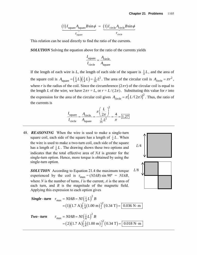
48. REASONING When the wire is used to make a single-turn
square coil, each side of the square has a length of 1
4L . When
the wire is used to make a two-turn coil, each side of the square
has a length of 1
8L . The drawing shows these two options and
indicates that the total effective area of NA is greater for the
single-turn option. Hence, more torque is obtained by using the
single-turn option.
SOLUTION According to Equation 21.4 the maximum torque
experienced by the coil is max = (NIAB) sin 90º = NIAB,
where N is the number of turns, I is the current, A is the area of
each turn, and B is the magnitude of the magnetic field.
Applying this expression to each option gives
21
max 42
14
21
max 82
18
1 1.7 A 1.00 m 0.34 T 0.036 N m
2 1.7 A 1.00 m 0.34 T 0.018 N m
NIAB NI L B
NIAB NI L B
Single - turn
Two - turn
L/4
L/8

1106 MAGNETIC FORCES AND MAGNETIC FIELDS
49. SSM REASONING The torque on the loop is given by Equation 21.4, NIABsin .
From the drawing in the text, we see that the angle between the normal to the plane of the
loop and the magnetic field is 9035 55. The area of the loop is
0.70 m 0.50 m = 0.35 m2.
SOLUTION
a. The magnitude of the net torque exerted on the loop is
NIABsin (75)(4.4 A)(0.35 m )(1.8 T) sin 55 = 170 N m2
b. As discussed in the text, when a current-carrying loop is placed in a magnetic field, the
loop tends to rotate such that its normal becomes aligned with the magnetic field. The
normal to the loop makes an angle of 55 with respect to the magnetic field. Since this angle
decreases as the loop rotates, the 35 angle increases .
50. REASONING AND SOLUTION According to Equation 21.4, the maximum torque for a
single turn is max
= IAB. When the length L of the wire is used to make the square, each
side of the square has a length L/4. The area of the square is Asquare
= (L/4)2. For the
rectangle, since two sides have a length d, while the other two sides have a length 2d, it
follows that L = 6d, or d = L/6. The area is Arectangle
= 2d2 = 2(L/6)2. Using Equation 21.4 for
the square and the rectangle, we obtain
square
rectangle
square
rectangle
square
rectangle
1 13 IA B
IA B
A
A
L
L
/
/
4
2 6
2
2
b gb g
.
51. REASONING The coil in the drawing is oriented such that the normal to the surface of the
coil is perpendicular to the magnetic field ( = 90). The magnetic torque is a maximum,
and Equation 21.4 gives its magnitude as = NIAB sin . In this expression N is the number
of loops in the coil, I is the current, A is the area of one loop, and B is the magnitude of the
magnetic field. The torque from the brake balances this magnetic torque. The brake torque is
brake
= Fbrake
r, where Fbrake
is the brake force, and r is the radius of the shaft and also the
lever arm. The maximum value for the brake force available from static friction is
Fbrake
= sF
N (Equation 4.7), where F
N is the normal force pressing the brake shoe against
the shaft. The maximum brake torque, then, is brake
= sF
Nr. By setting brake = max, we
will be able to determine the magnitude of the normal force.
SOLUTION Setting the torque produced by the brake equal to the maximum torque
produced by the coil gives
Chapter 21 Problems 1107
brake s N
–3 2
Ns
or sin
410 0.26 A 3.1 10 m 0.23 T sin 90sin8.3 N
0.76 0.012 m
F r NIAB
NIABF
r
52. REASONING The magnetic moment of the orbiting electron can be found from the
expression Magnetic moment NIA . For this situation, N 1. Thus, we need to find the
current and the area for the orbiting charge.
SOLUTION The current for the orbiting charge is, by definition (see Equation 20.1),
I q / t , where q is the amount of charge that passes a given point during a time
interval t. Since the charge (q = e) passes by a given point once per revolution, we can
find the current by dividing the total orbiting charge by the period T of revolution.
Iq
T
q
r v
2
10 10
101 06 10
/.
(1.6 C)(2.2 m / s)
2 (5.3 m)A
–19 6
–11
–3
The area of the orbiting charge is
A r 2 25 3 10 8 82 10( . ) .–11 –21 2 m m
Therefore, the magnetic moment is
Magnetic moment NIA ( )( . ) .1 1 06 10 10 3 10–3 –21 2 –24 2A)(8.82 m 9 A m
53. SSM REASONING AND SOLUTION
a. In Figure 21.27a the magnetic field that exists at the location of each wire points upward.
Since the current in each wire is the same, the fields at the locations of the wires also have
the same magnitudes. Therefore, a single external field that points downward will cancel
the mutual repulsion of the wires, if this external field has a magnitude that equals that of
the field produced by either wire.
b. Equation 21.5 gives the magnitude of the field produced by a long straight wire. The
external field must have this magnitude:
–7
404 10 T m/A 25 A
3 1 10 T2 2 0.016 m
IB
r
–.
1108 MAGNETIC FORCES AND MAGNETIC FIELDS
54. REASONING The magnitude B of the magnetic field in the interior of a long solenoid is
0B nI (Equation 21.7), where –70
4 10 T m/A is the permeability of free space,
n is the number of turns per unit length of the solenoid, and I is the current.
SOLUTION Using Equation 21.7, we find that
–7 –20
1400 turns4 10 T m/A 4.7 A 1.3 10 T
0.65 mB nI
55. SSM REASONING The magnitude B of the magnetic field in the interior of a solenoid
that has a length much greater than its diameter is given by 0
B nI (Equation 21.7),
where 70
4 10 T m/A is the permeability of free space, n is the number of turns per
meter of the solenoid’s length, and I is the current in the wire of the solenoid. Since B and I
are given, we can solve Equation 21.7 for n.
SOLUTION Solving Equation 21.7 for n, we find that the number of turns per meter of
length is
4
7 20
7.0 T2.8 10 turns/m
4 10 T m/A 2.0 10 A
Bn
I
56. REASONING The torque exerted on a coil with a current Icoil is given by
coilsinNI AB (Equation 21.4), where N is the number of turns in the coil, A is its area,
B is the magnitude of the external magnetic field causing the torque, and is the angle
between the normal to the surface of the coil and the direction of the external magnetic field.
The external magnetic field B, in this case, is the magnetic field of the solenoid. We will use
0B nI (Equation 21.7) to determine the magnetic field, where 7
04 10 T m/A is
the permeability of free space, n is the number of turns per meter of length of the solenoid,
and I is the current in the solenoid. The magnetic field in the interior of a solenoid is parallel
to the solenoid’s axis. Because the normal to the surface of the coil is perpendicular to the
axis of the solenoid, the angle is equal to 90.0°.
SOLUTION Substituting the expression 0
B nI (Equation 21.7) for the magnetic field of
the solenoid into coil
sinNI AB (Equation 21.4), we obtain
coil coil 0 0 coilsin sin sinNI AB NI A nI nNAI I
Therefore, the torque exerted on the coil is
7 1 3 2
4
4 10 T m/A 1400 m 50 1.2 10 m 0.50 A 3.5 A sin 90.0
1.8 10 N m

Chapter 21 Problems 1109
57. SSM REASONING The magnitude of the magnetic field at the center of a circular loop
of current is given by Equation 21.6 as B = N0I/(2R), where N is the number of turns, 0 is
the permeability of free space, I is the current, and R is the radius of the loop. The field is
perpendicular to the plane of the loop. Magnetic fields are vectors, and here we have two
fields, each perpendicular to the plane of the loop producing it. Therefore, the two field
vectors are perpendicular, and we must add them as vectors to get the net field. Since they
are perpendicular, we can use the Pythagorean theorem to calculate the magnitude of the net
field.
SOLUTION Using Equation 21.6 and the Pythagorean theorem, we find that the magnitude
of the net magnetic field at the common center of the two loops is
BN I
R
N I
R
N I
Rnet
T m / A A
2 0.040 m T
FHG
IKJ
FHG
IKJ
FHG
IKJ
0
2
0
2
0
7
5
2 22
2
2 1 4 10 1 73 8 10
bgc hb gb g
..
58. REASONING The two rods attract each other because they each carry a current I in the
same direction. The bottom rod floats because it is in equilibrium. The two forces that act
on the bottom rod are the downward force of gravity mg and the upward magnetic force of
attraction to the upper rod. If the two rods are a distance s apart, the magnetic field
generated by the top rod at the location of the bottom rod is (see Equation 21.5)
B I s 0
2/ ( ) . According to Equation 21.3, the magnetic force exerted on the bottom rod
is F I LB I L s sin sin / ( ) 0
2 2 , where is the angle between the magnetic field at
the location of the bottom rod and the direction of the current in the bottom rod. Since the
rods are parallel, the magnetic field is perpendicular to the direction of the current (RHR-2),
and 90 0. , so that sin =1.0 .
SOLUTION Taking upward as the positive direction, the net force on the bottom rod is
0
2
20
I L
smg
sin
Solving for I, we find
Imgs
L
2 2 8 2 10
100
(0.073 kg)(9.80 m / s m)
(4 T m / A)(0.85 m)190 A
2 –3
–7
)( .

1110 MAGNETIC FORCES AND MAGNETIC FIELDS
59. REASONING AND SOLUTION Let the current in the left-hand wire be labeled I1 and that
in the right-hand wire I2.
a. At point A: B
1 is up and B
2 is down, so we subtract them to get the net field. We have
B
1 = µ
0I1/(2 d
1) = µ
0(8.0 A)/[2 (0.030 m)]
B2 = µ
0I2/(2 d
2) = µ
0(8.0 A)/[2 (0.150 m)]
So the net field at point A is
BA = B
1 B
2 = 4.3 10 T5
b. At point B: B1 and B
2 are both down so we add the two. We have
B
1 =
0(8.0 A)/[2 (0.060 m)]
B2 =
0(8.0 A)/[2 (0.060 m)]
So the net field at point B is
BB = B
1 + B
2 = 5.3 10 T5
60. REASONING The net magnetic field is the sum of the uniform field and the field produced
by the current in the wire. In order for the net field to be zero, the two field contributions
must have the same magnitude and opposite directions. The current I in the wire creates a
field that has a magnitude B that is given by 0
2
IB
r
(Equation 21.5), where
–70
4 10 T m/A is the permeability of free space and r is the perpendicular distance
from the wire. We can solve this equation for r, in order to locate the point where the field
produced by the current has a magnitude of 37.00 10 T . Right-hand rule no. 2 indicates
that the field of the current has opposite directions on opposite sides of the wire. Therefore,
since the wire is perpendicular to the uniform field, we can be confident that this value for r
will locate a place on one side or the other of the wire where the net field is zero.
SOLUTION Solving Equation 21.5 for r, we find that
7
303
4 10 T m/A 305 A8.71 10 m
2 2 7.00 10 T
Ir
B
61. REASONING The magnitude Bi of the magnetic field at the center of the inner coil is given
by Equation 21.6 as i 0 i i i
/(2 )B µ I N R , where Ii, Ni, and Ri are, respectively, the current, the
number of turns, and the radius of the inner coil. The magnitude Bo of the magnetic field at
the center of the outer coil is o 0 o o o
/(2 )B µ I N R . In order that the net magnetic field at the
common center of the two coils be zero, the individual magnetic fields must have the same

Chapter 21 Problems 1111
magnitude, but opposite directions. Equating the magnitudes of the magnetic fields
produced by the inner and outer coils will allow us to find the current in the outer coil.
SOLUTION Setting Bi = Bo gives
0 i i 0 o o
i o
2 2
µ I N µ I N
R R
Solving this expression for the current in the outer coil, we have
oio i
o i
140 turns 0.023 m7.2 A 8.6 A
180 turns 0.015 m
RNI I
N R
In order that the two magnetic fields have opposite directions, the current in the outer coil
must have an opposite direction to the current in the inner coil.
62. REASONING
a. The compass needle lines up with the net
horizontal magnetic field B that is the vector sum
of the magnetic fields BI (the field at the location
of the compass due to the current I in the wire)
and BE (the horizontal component of the earth’s
magnetic field): B = BI + BE. The field lines of
the magnetic field created by the current I are
circles centered on the wire. Because the wire is
perpendicular to the earth’s surface, and the
compass is directly north of the wire, the magnetic
field BI due to the wire must point either due east
or due west at the location of the compass,
depending on the direction of the current. The
magnetic field BI causes the compass needle to
deflect east of north, so we conclude that BI points due east (see the drawing, which shows
the situation as viewed from above). We will use Right-Hand Rule No. 2 to determine the
direction of the current I from the direction of BI.
b. The horizontal component BE of the earth’s magnetic field points north, so it is
perpendicular to the magnetic field BI created by the current in the wire, which points east.
Therefore, the vectors B, BE, and BI form a right triangle with B serving as the hypotenuse
(see the drawing). The angle between the vectors BE and B, then, is given by I
E
tanB
B
(Equation 1.3). We will use 0
2
IB
r
(Equation 21.5) to determine BI, where r = 0.280 m is
compass
N
E W
S
B
0.28 m
BI
BE BE
BI
wire
(perpendicular to the page)
23.0°

1112 MAGNETIC FORCES AND MAGNETIC FIELDS
the radial distance between the wire and the center of the compass needle and 7
04 10 T m/A . Then we will use Equation 1.3 to find the magnitude BE of the
horizontal component of earth’s magnetic field.
SOLUTION
a. Because the magnetic field BI due to the current in the wire points east at the location of
the compass, the magnetic field lines must circulate clockwise around the wire, as viewed
from above. Right-Hand Rule No. 2, then, indicates that the current I flows into the page.
Since the drawing shows a top view of the situation, the current flows
toward the earth’s surface.
b. Solving I
E
tanB
B (Equation 1.3) for BE, we obtain
IE tan
BB
(1)
Substituting 0I 2
IB
r
(Equation 21.5) into Equation (1), we find that
0
0IE
42
tan tan 2 tan
I
IB rB
r
710 T m/A 25.0 A
2
54.21 10 T
0.280 m tan 23.0
63. REASONING The drawing shows an end-on view
of the two wires, with the currents directed out of the
plane of the paper toward you. B1 and B2 are the
individual fields produced by each wire. Applying
RHR-2 (thumb points in the direction of the current,
fingers curl into the shape of a half-circle and the
finger tips point in the direction of the field), we obtain the field directions shown in the
drawing for each of the three regions mentioned in the problem statement. Note that it is
only in the region between the wires that B1 and B2 have opposite directions. Hence, the
spot where the net magnetic field (the vector sum of the individual fields) is zero must lie
between the wires. At this spot the magnitudes of the fields B1 and B2 from the wires are
equal and each is given by 0
2
IB
r
(Equation 21.5), where μ0 is the permeability of free
space, I is the current in the wire, and r is the distance from the wire.
SOLUTION The spot we seek is located at a distance d from wire 1 (see the drawing).
Note that the wires are separated by a distance of one meter. Applying Equation 21.5 to
each wire, we have that
Wire 1 Wire 2
B1
B1
B1 B
2
B2
B2
d

Chapter 21 Problems 1113
0 1 0 2
1 2 or
2 2 1.00 m
I IB B
d d
Since 1 2
4I I , this result becomes
0 2 0 24 4 1
or or 4 1.00 m2 2 1.00 m 1.00 m
I Id d
d d d d
Solving for d, we find that 0.800 md
64. REASONING Using Right-Hand Rule No. 2, we can see that at point A the magnetic field
due to the horizontal current points perpendicularly out of the plane of the paper. Similarly,
the magnetic field due to the vertical current points perpendicularly into the plane of the
paper. Point A is closer to the horizontal wire, so that the effect of the horizontal current
dominates and the net field is directed out of the plane of the paper.
Using Right-Hand Rule No. 2, we can see that at point B the magnetic field due to the
horizontal current points perpendicularly into the plane of the paper. Similarly, the magnetic
field due to the vertical current points perpendicularly out of the plane of the paper. Point B
is closer to the horizontal wire, so that the effect of the horizontal current dominates and the
net field is directed into the plane of the paper.
Points A and B are the same distance of 0.20 m from the horizontal wire. They are also the
same distance of 0.40 m from the vertical wire. Therefore, the magnitude of the field
contribution from the horizontal current is the same at both points, although the directions of
the field contributions are opposite. Likewise, the magnitude of the field contribution from
the vertical current is the same at both points, although the directions of the field
contributions are opposite. At either point the magnitude of the net field is the magnitude of
the difference between the two contributions, and this is the same at points A and B.
SOLUTION According to Equation 21.5, the magnitude of the magnetic field from the
current in a long straight wire is B = 0I/(2 r), where 0 is the permeability of free space, I
is the current, and r is the distance from the wire. Applying this equation to each wire at
each point, we see that the magnitude of the net field Bnet is
0 0 0net
A, H A, V A, H A, V
Horizontal wire Vertical wire
7
6
1 1
2 2 2
4 10 T m/A 5.6 A 1 12.8 10 T
2 0.20 m 0.40 m
I I IB
r r r r
Point A

1114 MAGNETIC FORCES AND MAGNETIC FIELDS
0 0 0net
B, H B, V B, H B, V
Horizontal wire Vertical wire
7
6
1 1
2 2 2
4 10 T m/A 5.6 A 1 12.8 10 T
2 0.20 m 0.40 m
I I IB
r r r r
Point B
65. SSM REASONING According to Equation 21.6 the magnetic field at the center of a
circular, current-carrying loop of N turns and radius r is B N I r 0
2/ ( ) . The number of
turns N in the coil can be found by dividing the total length L of the wire by the
circumference after it has been wound into a circle. The current in the wire can be found by
using Ohm's law, I V R / .
SOLUTION The number of turns in the wire is
NL
r
2
The current in the wire is
IV
R L L
12 0
5 90 10
2 03 10. V
/ m)A
3
( .
.–3
Therefore, the magnetic field at the center of the coil is
B NI
r
L
r
I
r
LI
r
LL
FHG
IKJ
FHG
IKJFHG
IKJ
F
HGIKJ
0 0 0
2
2
2 2 2 4
1010
4 010
4 T m / A2.03
A
( 140 m1.04 T
–7
3
–2
c h. )
66. REASONING In the drawing at the right, we have
labeled the current on the left as I1 and its distance from
point P as r1. Similarly, we have labeled the current on the
right as I2 and its distance from point P as r2. In fact,
however, as the drawing in the text indicates, 1 2I I and
1 2r r (the dashed triangle is an equilateral triangle). It is
important to note that within the triangle the angle between r1
and the y axis is 30º, as is the angle between r2 and the y axis, because the y axis bisects
the 60º apex angle of the triangle. Moreover, it follows from right-hand rule no. 2 that the
magnetic field B1 (from current I1) is perpendicular to r1 and also that the magnetic field B2
(from current I2) is perpendicular to r2. This, in turn, means that the fields B1 and B2 make
r2 r
1
B2
30º
90º I1 x I
2
30º 30º 30º
B1
+x
+y
P

Chapter 21 Problems 1115
60º angles with the y axis, as indicated in the drawing. We will use this geometry in
dealing with the components of the two magnetic fields. It is necessary to use components
to find the net field at point P, since the fields are vectors.
SOLUTION The current I in each wire creates a field that has a magnitude B that is given
by 0
2
IB
r
(Equation 21.5), where –7
04 10 T m/A is the permeability of free
space and r is the perpendicular distance from the wire. Using Equation 21.5 for the
magnetic fields B1 and B2, we list the components of the fields at point P and the net
components as follows:
Field x component y component
B1 0
1 1sin60.0 sin60.0
2x
IB B
r
0
1 1cos60.0 cos60.0
2y
IB B
r
B2 0
2 2sin60.0 sin60.0
2x
IB B
r
0
2 2cos60.0 cos60.0
2y
IB B
r
Net 0 02 cos60.0
2
I
r
The net field at point P has a zero x component, so its magnitude is just the magnitude of the
y component:
7Magnitude
40of net field
at point
4 10 T m/A 85.0 A2 cos60.0 2 cos60.0 1.13 10 T
2 2 0.150 mP
I
r
Since the net field has only a y component that is negative, the net field points downward
and is perpendicular to the dashed line that is the base of the triangle in our drawing.
67. REASONING AND SOLUTION The forces acting on each wire
are the magnetic force F, the gravitational force mg, and the
tension T in the strings. Each string makes an angle of 7.5° with
respect to the vertical. From the drawing below at the right we
can relate the magnetic force to the gravitational force. Since the
wire is in equilibrium, Newton’s second law requires that
Fx = 0 and Fy = 0. These equations become
T sin 7.5 F
Fx
0 and T cos 7.5 mg
Fy
0
7 . 5o
T
mg
F +x
+y
Wire

1116 MAGNETIC FORCES AND MAGNETIC FIELDS
Solving the first equation for T, and then substituting the result into the second equation
gives (after some simplification)
tan 7.5 F
mg (1)
The magnetic force F exerted on one wire by the other is FI L
d
0
2
2, where d is the
distance between the wires [d/2 = (1.2 m) sin 7.5°, so that d = 0.31 m], I is the current
(which is the same for each wire), and L is the length of each wire. Substituting this relation
for F into Equation (1) and then solving for the current, gives
Im
Lg
d
FHG
IKJ
FHG
IKJ
LNM
OQP
tan .
. . tan ..
7 52
0 050 9 80 7 52 0 31
320
0
0
kg / m m / s
mA2b gc h b g
68. REASONING AND SOLUTION Ampère's law in the form of Equation 21.8 indicates that
|| 0B I . Since the magnetic field is everywhere perpendicular to the plane of the
paper, it is everywhere perpendicular to the circular path and has no component ||
B that is
parallel to the circular path. Therefore, Ampère's law reduces to || 0
0B I , so that
the net current passing through the circular surface is zero .
69. REASONING Since the two wires are next to each other, the net magnetic field is
everywhere parallel to in Figure 21.38. Moreover, the net magnetic field B has the same
magnitude B at each point along the circular path, because each point is at the same distance
from the wires. Thus, in Ampère's law (Equation 21.8), ||
B B , 1 2
I I I , and we have
|| 0 1 2B B I I
But is just the circumference (2r) of the circle, so Ampère's law becomes
0 1 22B r I I
This expression can be solved for B.
SOLUTION
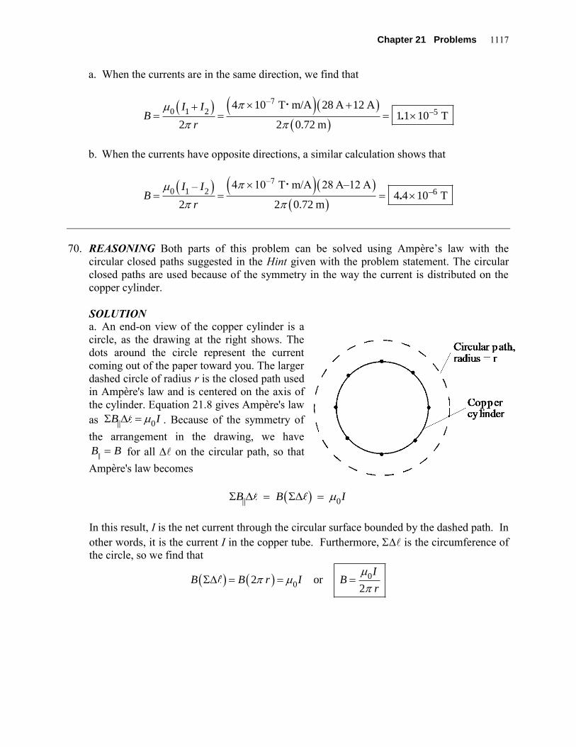
Chapter 21 Problems 1117
a. When the currents are in the same direction, we find that
–7
0 1 2 54 10 T m/A 28 A 12 A
1 1 10 T2 2 0.72 m
I IB
r
–.
b. When the currents have opposite directions, a similar calculation shows that
–7
0 1 2 64 10 T m/A 28 A–12 A–
4 4 10 T2 2 0.72 m
I IB
r
–.
70. REASONING Both parts of this problem can be solved using Ampère’s law with the
circular closed paths suggested in the Hint given with the problem statement. The circular
closed paths are used because of the symmetry in the way the current is distributed on the
copper cylinder.
SOLUTION
a. An end-on view of the copper cylinder is a
circle, as the drawing at the right shows. The
dots around the circle represent the current
coming out of the paper toward you. The larger
dashed circle of radius r is the closed path used
in Ampère's law and is centered on the axis of
the cylinder. Equation 21.8 gives Ampère's law
as || 0B I . Because of the symmetry of
the arrangement in the drawing, we have
B B|| for all on the circular path, so that
Ampère's law becomes
|| 0B B I
In this result, I is the net current through the circular surface bounded by the dashed path. In
other words, it is the current I in the copper tube. Furthermore, is the circumference of
the circle, so we find that
00
2 or2
IB B r I B
r

1118 MAGNETIC FORCES AND MAGNETIC FIELDS
b. The setup here is similar to that in part a, except that
the smaller dashed circle of radius r is now the closed
path used in Ampère's law (see the drawing at the
right). With this change, the derivation then proceeds
exactly as in part a. Now, however, there is no current
through the circular surface bounded by the dashed
path, because all of the current is outside the path.
Therefore, I = 0 A, and
BI
r
0
20 T
71. SSM REASONING AND SOLUTION The drawing
at the right shows an end-on view of the solid
cylinder. The dots represent the current in the
cylinder coming out of the paper toward you. The
dashed circle of radius r is the closed path used in
Ampère's law and is centered on the axis of the
cylinder. Equation 21.8 gives Ampère's law as
|| 0B I . Because of the symmetry of the
arrangement in the drawing, we have ||B B for all on the circular path, so that
Ampère's law becomes
|| 0B B I
In this result, = 2 r, the circumference of the circle. The current I is the part of the
total current that comes through the area 2r bounded by the dashed path. We can
calculate this current by using the current per unit cross-sectional area of the solid cylinder.
This current per unit area is called the current density. The current I is the current density
times the area 2r :
2
20 02 2
currentdensity
I I rI r
R R
Thus, Ampère's law becomes
2
0 0 00 0 2
or 2 or2
I r I rB I B r B
R 2 R
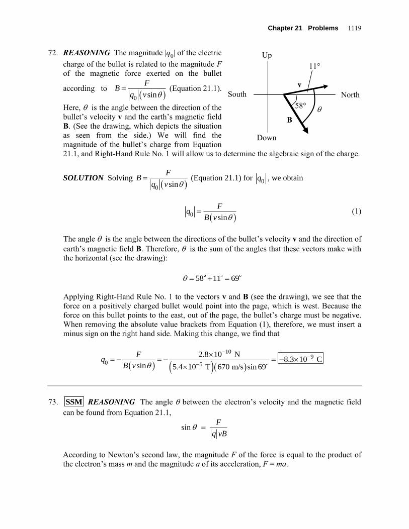
Chapter 21 Problems 1119
72. REASONING The magnitude |q0| of the electric
charge of the bullet is related to the magnitude F
of the magnetic force exerted on the bullet
according to 0
sin
FB
q v (Equation 21.1).
Here, is the angle between the direction of the
bullet’s velocity v and the earth’s magnetic field
B. (See the drawing, which depicts the situation
as seen from the side.) We will find the
magnitude of the bullet’s charge from Equation
21.1, and Right-Hand Rule No. 1 will allow us to determine the algebraic sign of the charge.
SOLUTION Solving 0
sin
FB
q v (Equation 21.1) for
0q , we obtain
0 sin
Fq
B v (1)
The angle is the angle between the directions of the bullet’s velocity v and the direction of
earth’s magnetic field B. Therefore, is the sum of the angles that these vectors make with
the horizontal (see the drawing):
58 11 69
Applying Right-Hand Rule No. 1 to the vectors v and B (see the drawing), we see that the
force on a positively charged bullet would point into the page, which is west. Because the
force on this bullet points to the east, out of the page, the bullet’s charge must be negative.
When removing the absolute value brackets from Equation (1), therefore, we must insert a
minus sign on the right hand side. Making this change, we find that
109
0 5
2.8 10 N8.3 10 C
sin 5.4 10 T 670 m/s sin 69
Fq
B v
73. SSM REASONING The angle between the electron’s velocity and the magnetic field
can be found from Equation 21.1,
sinF
q vB
According to Newton’s second law, the magnitude F of the force is equal to the product of
the electron’s mass m and the magnitude a of its acceleration, F = ma.
58°
11°
v
B
North South
Up
Down

1120 MAGNETIC FORCES AND MAGNETIC FIELDS
SOLUTION The angle is
31 14 2
1 1
19 6 4
9.11 10 kg 3.50 10 m/ssin sin 19.7
1.60 10 C 6.80 10 m/s 8.70 10 T
ma
q vB
74. REASONING At the center of the loop, the magnitude B of the magnetic field due to the
current I in the long, straight wire is equal to the magnitude Bloop of the magnetic field due
to the current Iloop in the circular wire loop. We know this because the vector sum of the two
magnetic fields at that location is zero. We will determine the magnitude of the magnetic
field due to the current in the circular loop from 0 loop
loop 2
IB
R
(Equation 21.6, with
N = 1), where 70
4 10 T m/A is the permeability of free space, and R is the radius of
the loop. The magnitude B of the magnetic field of the long, straight wire is given by
0
2
IB
r
(Equation 21.5), where r is the radial distance from the wire to the center of the
loop. Because the wire is tangent to the loop, the radial distance r is equal to the radius R of
the loop, and we have that
0
2
IB
R
(1)
SOLUTION The two magnetic fields have equal magnitudes at the center of the circular
loop, so 0 loop
loop 2
IB
R
(Equation 21.6) and Equation (1) together yield
0 loop 0
loop 2 2
I IB B
R R
(2)
Solving Equation (2) for Iloop, we obtain
0
loop
2
I
R
0
2
I
R loop
0.12 A or 0.038 A
II
75. SSM REASONING According to Equation 21.4, the maximum torque is max
= NIAB,
where N is the number of turns in the coil, I is the current, A = r2 is the area of the circular
coil, and B is the magnitude of the magnetic field. Since the coil contains only one turn, the
length L of the wire is the circumference of the circle, so that L = 2 r or r = L/(2). Since
N, I, and B are known we can solve for L.
SOLUTION According to Equation 21.4 and the fact that r = L/(2), we have
max
FHG
IKJNI r B NI
LB2
2
2

Chapter 21 Problems 1121
Solving this result for L gives
LNIB
4 4 8 4 10
1 3 7 0 750 062
4
max N m
A T m
.
. ..
c hbgb gb g
76. REASONING The magnitude of the magnetic force acting on the particle is
F = 0
q vB sin (Equation 21.1), where 0
q and v are the charge magnitude and speed of
the particle, respectively, B is the magnitude of the magnetic field, and is the angle
between the particle’s velocity and the magnetic field. The magnetic field is produced by a
very long, straight wire, so its value is given by Equation 21.5 as 0/ 2B I r . By
combining these two relations, we can determine the magnitude of the magnetic force.
SOLUTION The direction of the magnetic field B
produced by the current-carrying wire can be found by
using Right-Hand Rule No. 2. At the location of the
charge, this field points perpendicularly into the page,
as shown in the drawing. Since the direction of the
particle’s velocity is perpendicular to the magnetic
field, = 90.0. Substituting 0/ 2B I r into
F = 0q vB sin gives
00 0
6 4 7
4
2
sin sin2
6.00 10 C 7.50 10 m/s 4 10 T m/A 67.0 A sin 90.01.21 10 N
2 5.00 10 m
IF q vB q v
r
The direction of the magnetic force F exerted on the particle can be determined by using
Right-Hand Rule No. 1. This direction, which is shown in the drawing, is
perpendicular to the wire and is directed away from it .
77. REASONING A maximum magnetic force is exerted on the wire by the field components
that are perpendicular to the wire, and no magnetic force is exerted by field components that
are parallel to the wire. Thus, the wire experiences a force only from the x- and y-
components of the field. The z-component of the field may be ignored, since it is parallel to
the wire. We can use the Pythagorean theorem to find the net field in the x, y plane. This net
field, then, is perpendicular to the wire and makes an angle of = 90 with respect to the
wire. Equation 21.3 can be used to calculate the magnitude of the magnetic force that this
net field applies to the wire.
v
I
q
B (into page)
F

1122 MAGNETIC FORCES AND MAGNETIC FIELDS
SOLUTION According to Equation 21.3, the magnetic force has a magnitude of
F = ILB sin , where I is the current, B is the magnitude of the magnetic field, L is the length
of the wire, and is the angle of the wire with respect to the field. Using the Pythagorean
theorem, we find that the net field in the x, y plane is
B B Bx y
2 2
Using this field in Equation 21.3, we calculate the magnitude of the magnetic force to be
F ILB IL B Bx y
sin = sin
A 0.25 m 0.10 T 0.15 T sin = 0.19 N
2 2
2 24 3 90.b gb gb g b g
78. REASONING The current I is the rate of flow of charge and is q
It
(Equation 20.1),
where Δq is the amount of charge that flows in a time period Δt. We can solve this equation
for Δq. The current is not given. However, since we are assuming that the bolt can be
represented as a long, straight line of current, we can obtain the current from the information
provided about the magnetic field B. The field is 0
2
IB
r
(Equation 21.5), where
–70
4 10 T m/A is the permeability of free space and r is the perpendicular distance
from the current.
SOLUTION Solving Equation 20.1 for the charge Δq, we have
or q
I q I tt
Solving Equation 21.5 for the current I, we have
0
0
2 or
2
I B rB I
r
Substituting this result for I into the expression for Δq, we find that
5
37
0
8.0 10 T 2 27 m21.8 10 s 19 C
4 10 T m/A
B rq I t t
79. REASONING When a charge q0 travels at a speed v and its velocity makes an angle with
respect to a magnetic field of magnitude B, the magnetic force acting on the charge has a
magnitude F that is given by 0sinF q vB (Equation 21.1). We will solve this problem
by applying this expression twice, first to the motion of the charge when it moves
perpendicular to the field so that = 90.0 and then to the motion when = 38.

Chapter 21 Problems 1123
SOLUTION When the charge moves perpendicular to the field so that = 90.0,
Equation 21.1 indicates that
90.0 0sin90.0F q vB
When the charge moves so that = 38, Equation 21.1 shows that
38 0sin38F q vB
Dividing the second expression by the first expression gives
038
90.0 0
3 338 90.0
sin 38
sin 90.0
sin 38 sin 38 2.7 10 N 1.7 10 N
sin 90.0 sin 90.0
q vBF
F q vB
F F
80. REASONING Each of the four wires makes a contribution to the net magnetic field B at
the center of the square. The magnitude of each wire’s magnetic field is given by
0
2
IB
r
(Equation 21.5), where I is the current in a wire, r is the radial distance from the
wire to the center of the square, and 70
4 10 T m/A is the permeability of free
space. For all four wires, the radial distance r is half of the length s of one of the sides of the
square 12
r s .
In order to add up the four magnetic fields, we must determine the direction of each one.
Right-Hand Rule No. 2 predicts that, at the center of the square, the currents I1 = 3.9 A,
I2 = 8.5 A, and I3 = 4.6 A all produce fields pointing into the page, while the magnetic field
B of the unknown current I points out of the page. Therefore, the magnitude Bnet of the net
magnetic field is given by
net 1 2 3B B B B B (1)
SOLUTION Applying 0
2
IB
r
(Equation 21.5) to the magnetic fields on the right side of
Equation (1), we obtain
0 1 0 2 0 3 0 0net 1 2 32 2 2 2 2
I I I IB I I I I
r r r r r
(2)
Solving Equation (2) for I yields
net net1 2 3 1 2 3
0 0
2 2 or
rB rBI I I I I I I I
(3)

1124 MAGNETIC FORCES AND MAGNETIC FIELDS
The length s of a side of the square is s = 0.050 m, so the radial distance r from each wire to
the center of the square is half as large: r = 12
s = 0.025 m. Therefore, Equation (3) yields
23.9 A 8.5 A 4.6 AI
60.025 m 61 10 T
4
79.4 A
10 T m/A
81. SSM REASONING From the discussion
in Section 21.3, we know that when a
charged particle moves perpendicular to a
magnetic field, the trajectory of the particle is
a circle. The drawing at the right shows a
particle moving in the plane of the paper (the
magnetic field is perpendicular to the paper).
If the particle is moving initially through the
coordinate origin and to the right (along the
+x axis), the subsequent circular path of the
particle will intersect the y axis at the
greatest possible value, which is equal to
twice the radius r of the circle.
ymax
r
x
Particle
v
y
SOLUTION a. From the drawing above, it can be seen that the largest value of y is equal to the diameter
(2r) of the circle. When the particle passes through the coordinate origin its velocity must be
parallel to the +x axis. Thus, the angle is 0 .
b. The maximum value of y is twice the radius r of the circle. According to Equation 21.2,
the radius of the circular path is /r mv q B . The maximum value ymax is, therefore,
–8
max –6
3.8 10 kg 44 m/s2 2 2 0.29 m
7.3 10 C 1.6 T
mvy r
q B
82. REASONING
a. If the particle is stationary, only the electric field Ex exerts a force on it; this force is
FE = q Ex (Equation 18.2), where q is the charge. A magnetic field does not exert a force on
a stationary particle.

Chapter 21 Problems 1125
b. If the particle is moving along the +x axis, the electric field exerts a force on it. This force
is the same as that in part (a) above. The magnetic field Bx does not exert a force on the
particle, because the particle’s velocity is parallel to the field. The magnetic field By does
exert a force on the particle, because the particle’s velocity is perpendicular to this field.
c. The particle experiences a force from each of the three fields. The electric field exerts a
force on it, and this force is the same as that in part (a) above. It does not matter in which
direction the particle travels, for the electric force is independent of the particle’s velocity.
The particle experiences magnetic forces from both Bx and By. When the particle moves
along the +z axis, its velocity is perpendicular to both Bx and By, so each field exerts a force
on the particle.
.
SOLUTION
a. The electric force exerted on the particle is FE = q Ex (Equation 18.2), so
6 35.60 10 C 245 N/C 1.37 10 NE xF qE
where the plus sign indicates that the force points along the axisx . The magnitude F of
the magnetic force is given by Equation 21.1 as 0
sinF q vB . Since v = 0 m/s, the
magnetic forces exerted by Bx and By are zero:
0 N 0 NB Bx y
F F
b. The electric force is the same as that computed in part (a), because this force does not
depend on the velocity of the particle: 31.37 10 NE
F , where the plus sign indicates
that the force points along the axisx .
Since the velocity of the particle and Bx are along the +x axis 0 in Equation 21.1 , the
magnitude of the magnetic force is
0 0sin sin 0 0 N
B x xxF q vB q vB
The magnetic force exerted by the magnetic field By on the charge has a magnitude of
6 30
sin 5.60 10 C 375 m/s 1.40 T sin90.0 2.94 10 NyB y
F q vB
An application of Right-hand Rule No. 1 shows that the direction of the magnetic force is
along the axisz .
1126 MAGNETIC FORCES AND MAGNETIC FIELDS
c. The electric force is the same as that computed in part (a), because this force does not
depend on the velocity of the particle: 31.37 10 NE
F , where the plus sign indicates
that the force points along the axisx .
When the particle moves along the +z axis, the magnetic field Bx exerts a force on the
charge that has a magnitude of
6 30
sin 5.60 10 C 375 m/s 1.80 T sin90.0 3.78 10 NB xx
F q vB
An application of Right-hand Rule No. 1 shows that the direction of the magnetic force is
along the axisy .
When the particle moves along the +z axis, the magnetic field By exerts a force on the
charge that has a magnitude of
6 30
sin 5.60 10 C 375 m/s 1.40 T sin90.0 2.94 10 NyB y
F q vB
An application of Right-hand Rule No. 1 shows that the direction of the magnetic force is
along the axisx .
83. REASONING Two wires that are parallel and carry current in the same direction exert
attractive magnetic forces on one another, as Section 21.7 discusses. This attraction
between the wires causes the spring to compress. When compressed, the spring exerts an
elastic restoring force on each wire, as Section 10.1 discusses. For each wire, this restoring
force acts to push the wires apart and balances the magnetic force, thus keeping the
separation between the wires from decreasing to zero. Equation 10.2 (without the minus
sign) gives the magnitude of the restoring force as Fx = kx, where k is the spring constant
and x is the magnitude of the displacement of the spring from its unstrained length. By
setting the magnitude of the magnetic force equal to the magnitude of the restoring force, we
will be able to find the separation between the rods when the current is present.
SOLUTION According to Equation 21.3, the magnetic force has a magnitude of
F = ILB sin , where I is the current, B is the magnitude of the magnetic field, L is the length
of the wire, and is the angle of the wire with respect to the field. Using RHR-2 reveals
that the magnetic field produced by either wire is perpendicular to the other wire, so that
= 90 in Equation 21.3, which becomes F = ILB. According to Equation 21.5 the
magnitude of the magnetic field produced by a long straight wire is B = 0I/(2 r).
Substituting this expression into Equation 21.3 gives the magnitude of the magnetic force as
Chapter 21 Problems 1127
F ILI
r
I L
r
FHG
IKJ
0 0
2
2 2
Equating this expression to the magnitude of the restoring force from the spring gives
0
2
2
I L
rk x
Solving for the separation r, we find
rI L
k x
0
2 7 2
2
4 10 950 0 50
2 150 0 0200 030
T m / A A m
N / m m m
c hb gb gb gb g
.
..
84. REASONING The turns of the coil are as close together as possible without overlapping,
meaning that there are no gaps between the turns. Therefore, the width of a single turn is
equal to the diameter D = 2r of the wire, where r is the wire’s radius. The number N of
turns, therefore, is N = L/(2r), where L is the length of the solenoid. The number of turns per
unit length is n, where
/ 2 1
2
N L rn
L L r (1)
The magnitude B of the magnetic field inside a solenoid with n turns per meter and a current
I is given by 0B nI (Equation 21.7), where 7
04 10 T m/A is the permeability of
free space. We will use Ohm’s law, V
RI
(Equation 20.2), to determine the current I in the
solenoid when the battery (Emf = V) is connected to it. The resistance R of the silver wire
will be found from L
RA
(Equation 20.3), where = 1.59×10⁻⁸ ∙m is the resistivity of
silver (see Table 20.1), L is the length of the wire, and A is its cross-sectional area.
SOLUTION Substituting Equation (1) into 0B nI (Equation 21.7) and solving for the
radius r yields
0 00
or 2 2
I IB nI r
r B
(2)
Solving V
RI
(Equation 20.2) for I, we obtain V
IR
. Substituting this result into
Equation (2), we find that
0 0
2 2
I Vr
B BR
(3)
Substituting L
RA
(Equation 20.3) into Equation (3), we obtain

1128 MAGNETIC FORCES AND MAGNETIC FIELDS
0 0 0
2 22
V V VAr
LBR B LB
A
(4)
The wire has a circular cross-section, so we may express the area A in Equation (4) as
A = r2. Substituting this expression into Equation (4) and simplifying the resulting
expression, we find that
r
20V r
0 or 12 2
V r
B L B L
(5)
Solving Equation (5) for r yields
3 8
4
70
2 6.48 10 T 1.59 10 m 25.0 m24.35 10 m
4 10 T m/A 3.00 V
B Lr
V
85. SSM REASONING The magnetic moment of the rotating charge can be found from the
expression Magnetic moment NIA , as discussed in Section 21.6. For this situation, N 1.
Thus, we need to find the current and the area for the rotating charge. This can be done by
resorting to first principles.
SOLUTION The current for the rotating charge is, by definition (see Equation 20.1),
I q / t , where q is the amount of charge that passes by a given point during a time
interval t. Since the charge passes by once per revolution, we can find the current by
dividing the total rotating charge by the period T of revolution.
–6
–5(150 rad/s)(4.0 10 C)9.5 10 A
2 / 2 2
q q qI
T
The area of the rotating charge is 2 2 2(0.20 m) 0.13 mA r
Therefore, the magnetic moment is
–5 2 –5 2(1)(9.5 10 A)(0.13 m ) 1.2 10 A mMagnetic moment NIA