Chapter 2 Static Routing -...
105
Chapter 2 Static Routing João José [email protected] http://w3.ualg.pt/~jjose/cisco/ Based on: Graziani, R. (2008) CIS 82 Routing Theory and Concepts Cisco CCNA 2 Exploration - Routing
Transcript of Chapter 2 Static Routing -...

Chapter 2
Static Routing
João José
http://w3.ualg.pt/~jjose/cisco/
Based on:
Graziani, R. (2008) CIS 82 Routing Theory and Concepts
Cisco CCNA 2 Exploration - Routing
Routers and the Network
Role of the Router
Introducing the Topology
Examining the Connection on the Router
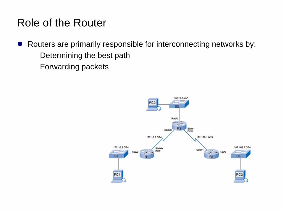
Role of the Router
Routers are primarily responsible for interconnecting networks by:
Determining the best path
Forwarding packets
Introducing the Topology
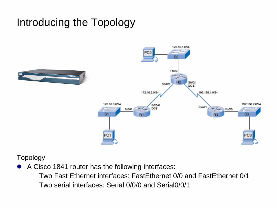
Topology
A Cisco 1841 router has the following interfaces:
Two Fast Ethernet interfaces: FastEthernet 0/0 and FastEthernet 0/1
Two serial interfaces: Serial 0/0/0 and Serial0/0/1
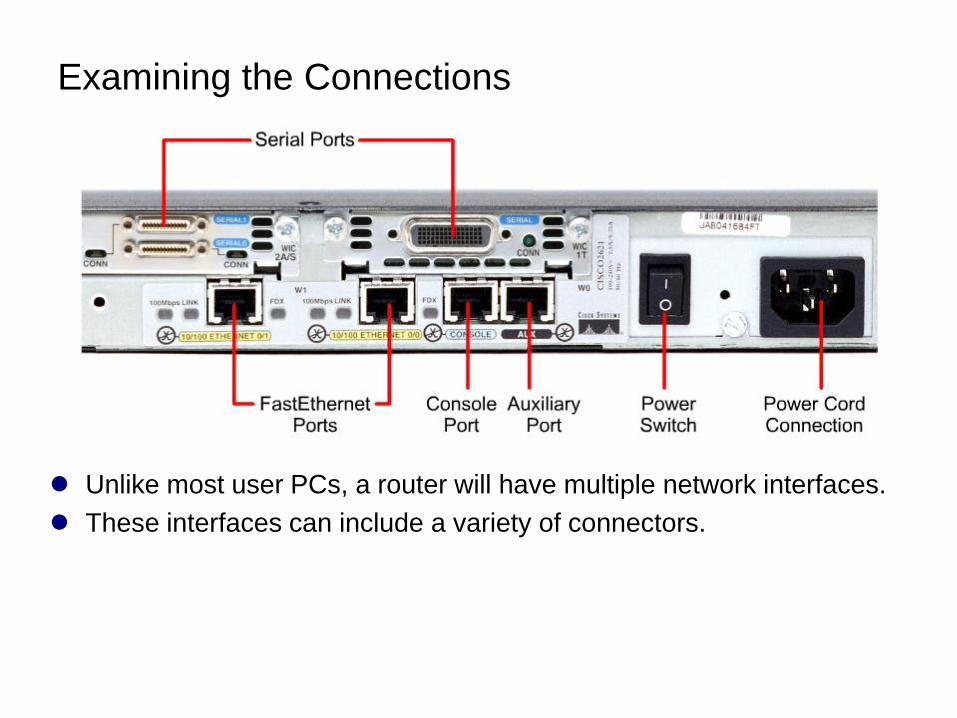
Examining the Connections
Unlike most user PCs, a router will have multiple network interfaces.
These interfaces can include a variety of connectors.
Serial Connectors
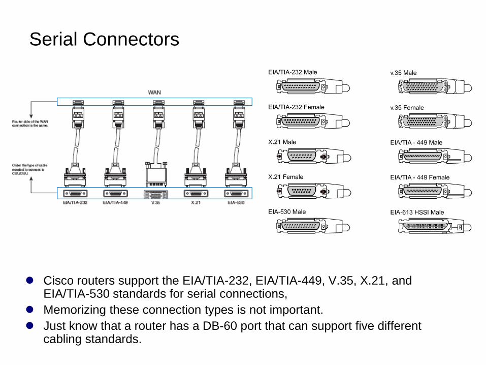
Cisco routers support the EIA/TIA-232, EIA/TIA-449, V.35, X.21, and EIA/TIA-530 standards for serial connections,
Memorizing these connection types is not important.
Just know that a router has a DB-60 port that can support five different cabling standards.
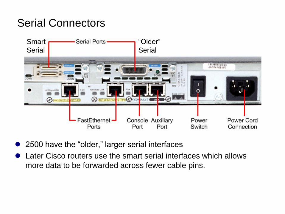
Serial Connectors
2500 have the ―older,‖ larger serial interfaces
Later Cisco routers use the smart serial interfaces which allows
more data to be forwarded across fewer cable pins.
Smart
Serial
―Older‖
Serial
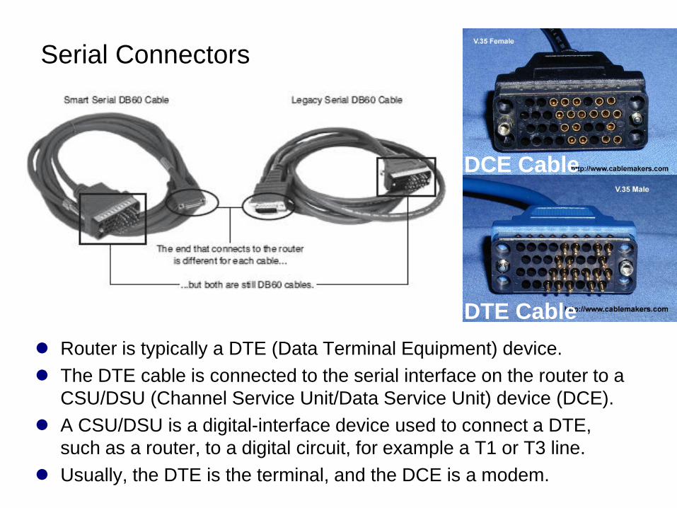
Serial Connectors
Router is typically a DTE (Data Terminal Equipment) device.
The DTE cable is connected to the serial interface on the router to a
CSU/DSU (Channel Service Unit/Data Service Unit) device (DCE).
A CSU/DSU is a digital-interface device used to connect a DTE,
such as a router, to a digital circuit, for example a T1 or T3 line.
Usually, the DTE is the terminal, and the DCE is a modem.
DTE Cable
DCE Cable
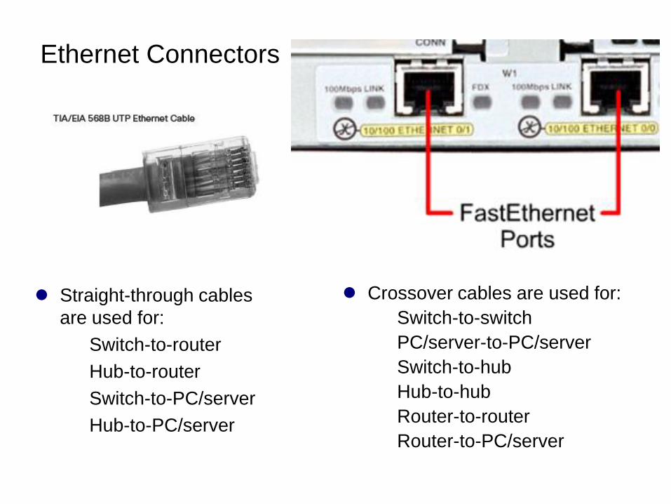
Ethernet Connectors
Straight-through cables
are used for:
Switch-to-router
Hub-to-router
Switch-to-PC/server
Hub-to-PC/server
Crossover cables are used for:
Switch-to-switch
PC/server-to-PC/server
Switch-to-hub
Hub-to-hub
Router-to-router
Router-to-PC/server
Router Configuration Review
Examining Router Interfaces
Configuring an Ethernet Interface
Verifying Ethernet Addresses
Configuring a Serial Interfaces
Examining Serial Interfaces
Examining Router Interfaces
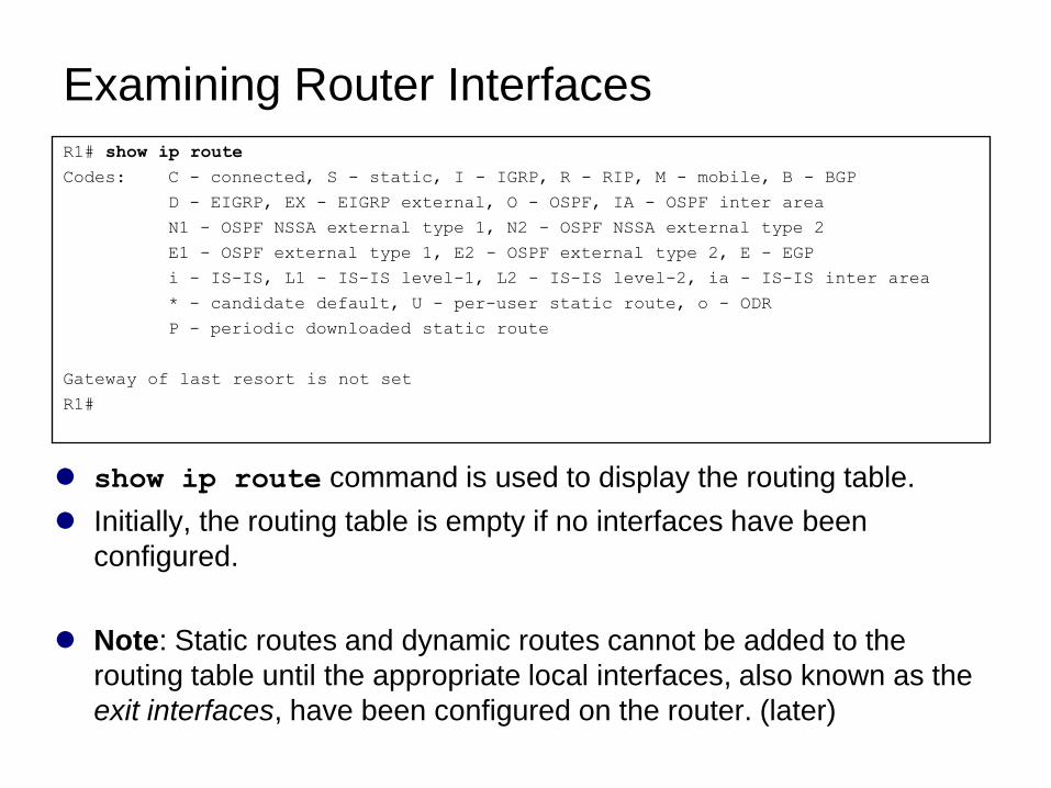
show ip route command is used to display the routing table.
Initially, the routing table is empty if no interfaces have been
configured.
Note: Static routes and dynamic routes cannot be added to the
routing table until the appropriate local interfaces, also known as the
exit interfaces, have been configured on the router. (later)
R1# show ip route
Codes: C - connected, S - static, I - IGRP, R - RIP, M - mobile, B - BGP
D - EIGRP, EX - EIGRP external, O - OSPF, IA - OSPF inter area
N1 - OSPF NSSA external type 1, N2 - OSPF NSSA external type 2
E1 - OSPF external type 1, E2 - OSPF external type 2, E - EGP
i - IS-IS, L1 - IS-IS level-1, L2 - IS-IS level-2, ia - IS-IS inter area
* - candidate default, U - per-user static route, o - ODR
P - periodic downloaded static route
Gateway of last resort is not set
R1#
Interfaces and their Statuses
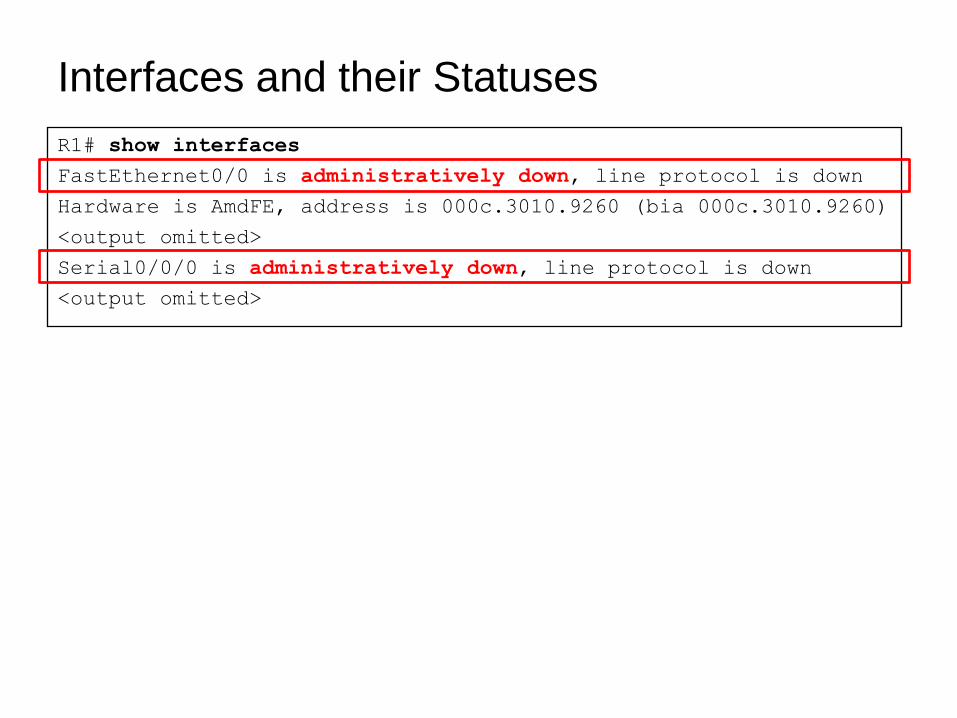
R1# show interfaces
FastEthernet0/0 is administratively down, line protocol is down
Hardware is AmdFE, address is 000c.3010.9260 (bia 000c.3010.9260)
<output omitted>
Serial0/0/0 is administratively down, line protocol is down
<output omitted>
Interfaces and their Statuses
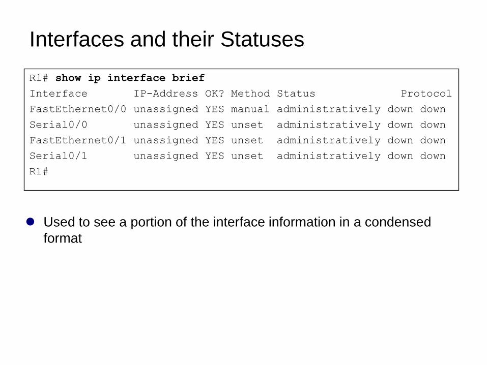
Used to see a portion of the interface information in a condensed
format
R1# show ip interface brief
Interface IP-Address OK? Method Status Protocol
FastEthernet0/0 unassigned YES manual administratively down down
Serial0/0 unassigned YES unset administratively down down
FastEthernet0/1 unassigned YES unset administratively down down
Serial0/1 unassigned YES unset administratively down down
R1#
Interfaces and their Statuses
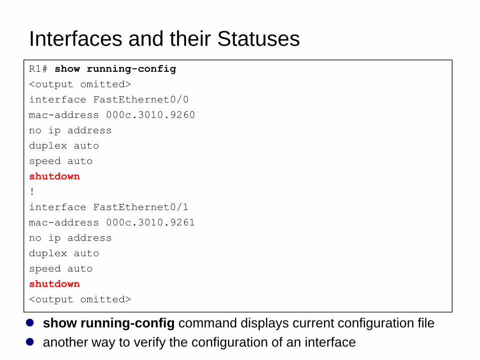
show running-config command displays current configuration file
another way to verify the configuration of an interface
R1# show running-config
<output omitted>
interface FastEthernet0/0
mac-address 000c.3010.9260
no ip address
duplex auto
speed auto
shutdown
!
interface FastEthernet0/1
mac-address 000c.3010.9261
no ip address
duplex auto
speed auto
shutdown
<output omitted>
Configuring an Ethernet Interface
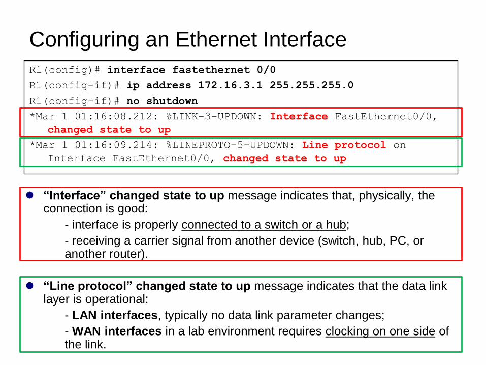
“Interface” changed state to up message indicates that, physically, the connection is good:
- interface is properly connected to a switch or a hub;
- receiving a carrier signal from another device (switch, hub, PC, or another router).
“Line protocol” changed state to up message indicates that the data link layer is operational:
- LAN interfaces, typically no data link parameter changes;
- WAN interfaces in a lab environment requires clocking on one side of the link.
R1(config)# interface fastethernet 0/0
R1(config-if)# ip address 172.16.3.1 255.255.255.0
R1(config-if)# no shutdown
*Mar 1 01:16:08.212: %LINK-3-UPDOWN: Interface FastEthernet0/0,
changed state to up
*Mar 1 01:16:09.214: %LINEPROTO-5-UPDOWN: Line protocol on
Interface FastEthernet0/0, changed state to up
Unsolicited Messages from IOS
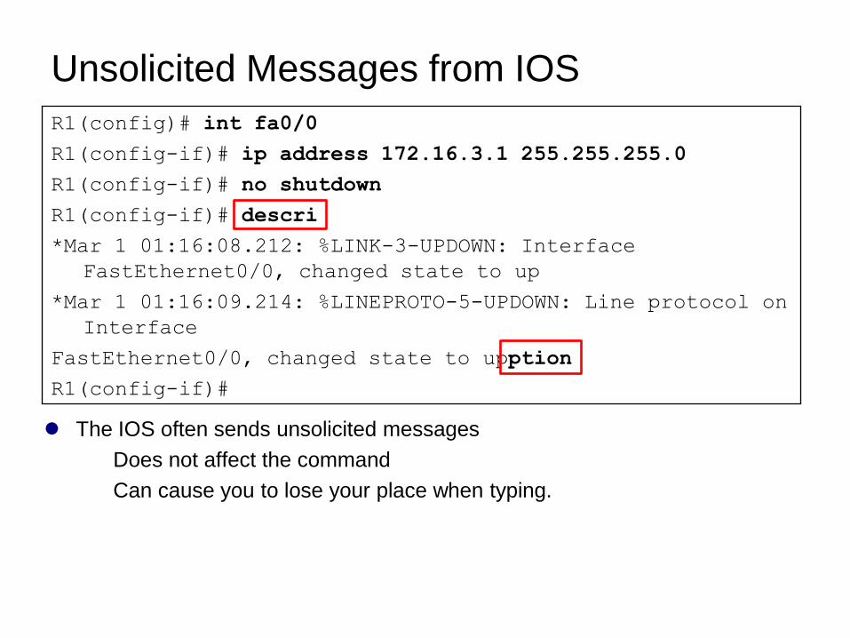
The IOS often sends unsolicited messages
Does not affect the command
Can cause you to lose your place when typing.
R1(config)# int fa0/0
R1(config-if)# ip address 172.16.3.1 255.255.255.0
R1(config-if)# no shutdown
R1(config-if)# descri
*Mar 1 01:16:08.212: %LINK-3-UPDOWN: Interface
FastEthernet0/0, changed state to up
*Mar 1 01:16:09.214: %LINEPROTO-5-UPDOWN: Line protocol on
Interface
FastEthernet0/0, changed state to upption
R1(config-if)#
Unsolicited Messages from IOS
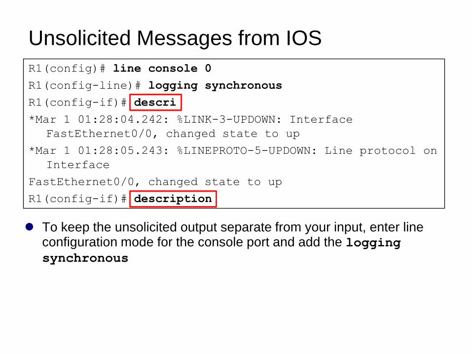
To keep the unsolicited output separate from your input, enter line configuration mode for the console port and add the logging synchronous
R1(config)# line console 0
R1(config-line)# logging synchronous
R1(config-if)# descri
*Mar 1 01:28:04.242: %LINK-3-UPDOWN: Interface
FastEthernet0/0, changed state to up
*Mar 1 01:28:05.243: %LINEPROTO-5-UPDOWN: Line protocol on
Interface
FastEthernet0/0, changed state to up
R1(config-if)# description
Reading the Routing Table
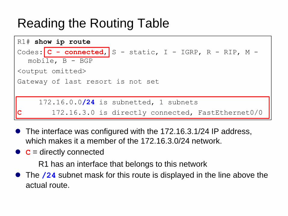
The interface was configured with the 172.16.3.1/24 IP address,
which makes it a member of the 172.16.3.0/24 network.
C = directly connected
R1 has an interface that belongs to this network
The /24 subnet mask for this route is displayed in the line above the
actual route.
R1# show ip route
Codes: C - connected, S - static, I - IGRP, R - RIP, M -
mobile, B - BGP
<output omitted>
Gateway of last resort is not set
172.16.0.0/24 is subnetted, 1 subnets
C 172.16.3.0 is directly connected, FastEthernet0/0
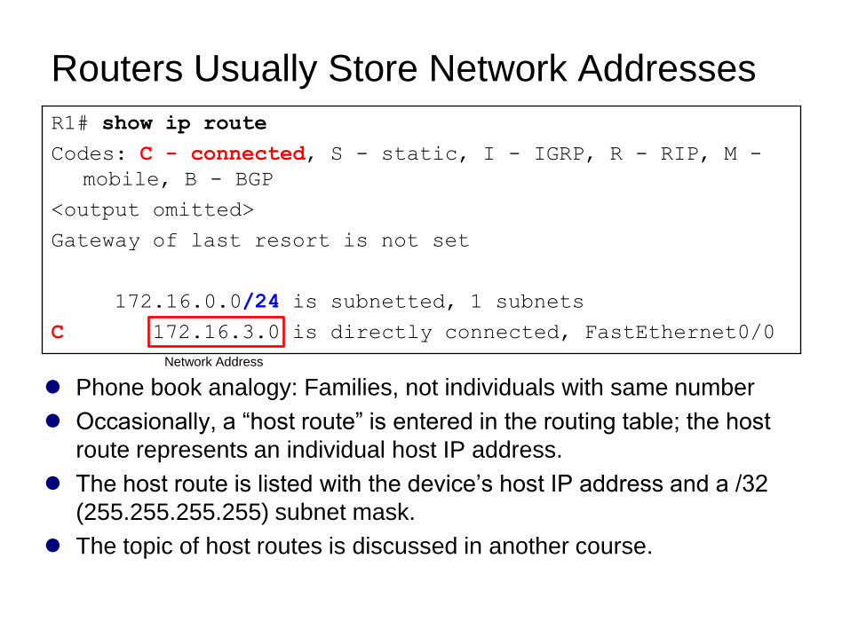
Routers Usually Store Network Addresses
Phone book analogy: Families, not individuals with same number
Occasionally, a ―host route‖ is entered in the routing table; the host
route represents an individual host IP address.
The host route is listed with the device’s host IP address and a /32
(255.255.255.255) subnet mask.
The topic of host routes is discussed in another course.
R1# show ip route
Codes: C - connected, S - static, I - IGRP, R - RIP, M -
mobile, B - BGP
<output omitted>
Gateway of last resort is not set
172.16.0.0/24 is subnetted, 1 subnets
C 172.16.3.0 is directly connected, FastEthernet0/0
Network Address
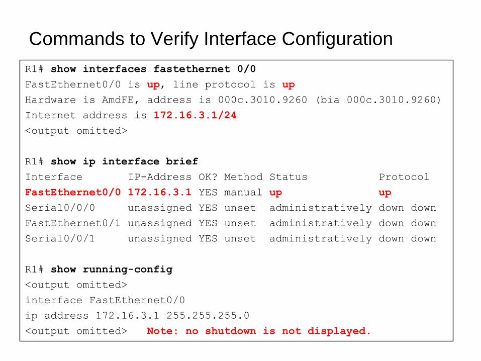
Commands to Verify Interface Configuration
R1# show interfaces fastethernet 0/0
FastEthernet0/0 is up, line protocol is up
Hardware is AmdFE, address is 000c.3010.9260 (bia 000c.3010.9260)
Internet address is 172.16.3.1/24
<output omitted>
R1# show ip interface brief
Interface IP-Address OK? Method Status Protocol
FastEthernet0/0 172.16.3.1 YES manual up up
Serial0/0/0 unassigned YES unset administratively down down
FastEthernet0/1 unassigned YES unset administratively down down
Serial0/0/1 unassigned YES unset administratively down down
R1# show running-config
<output omitted>
interface FastEthernet0/0
ip address 172.16.3.1 255.255.255.0
<output omitted> Note: no shutdown is not displayed.
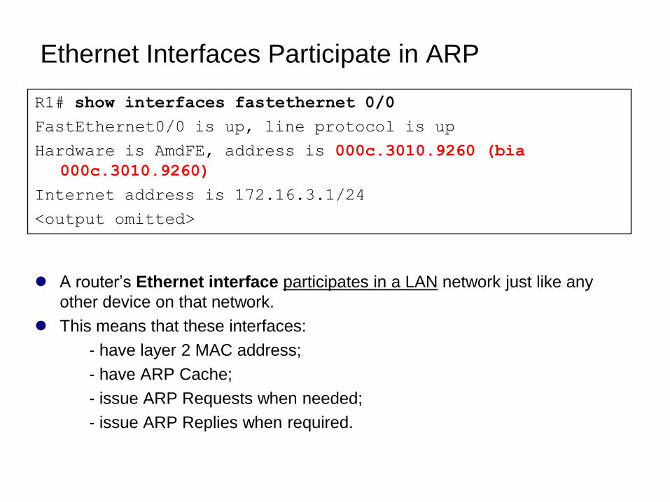
Ethernet Interfaces Participate in ARP
A router’s Ethernet interface participates in a LAN network just like any
other device on that network.
This means that these interfaces:
- have layer 2 MAC address;
- have ARP Cache;
- issue ARP Requests when needed;
- issue ARP Replies when required.
R1# show interfaces fastethernet 0/0
FastEthernet0/0 is up, line protocol is up
Hardware is AmdFE, address is 000c.3010.9260 (bia
000c.3010.9260)
Internet address is 172.16.3.1/24
<output omitted>
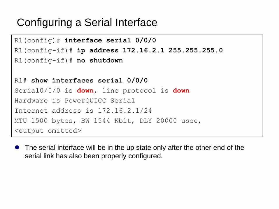
Configuring a Serial Interface
The serial interface will be in the up state only after the other end of the
serial link has also been properly configured.
R1(config)# interface serial 0/0/0
R1(config-if)# ip address 172.16.2.1 255.255.255.0
R1(config-if)# no shutdown
R1# show interfaces serial 0/0/0
Serial0/0/0 is down, line protocol is down
Hardware is PowerQUICC Serial
Internet address is 172.16.2.1/24
MTU 1500 bytes, BW 1544 Kbit, DLY 20000 usec,
<output omitted>
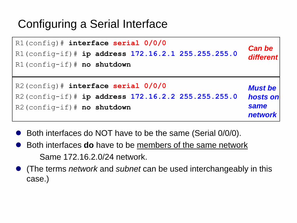
Configuring a Serial Interface
Both interfaces do NOT have to be the same (Serial 0/0/0).
Both interfaces do have to be members of the same network
Same 172.16.2.0/24 network.
(The terms network and subnet can be used interchangeably in this
case.)
R1(config)# interface serial 0/0/0
R1(config-if)# ip address 172.16.2.1 255.255.255.0
R1(config-if)# no shutdown
R2(config)# interface serial 0/0/0
R2(config-if)# ip address 172.16.2.2 255.255.255.0
R2(config-if)# no shutdown
Can be
different
Must be
hosts on
same
network
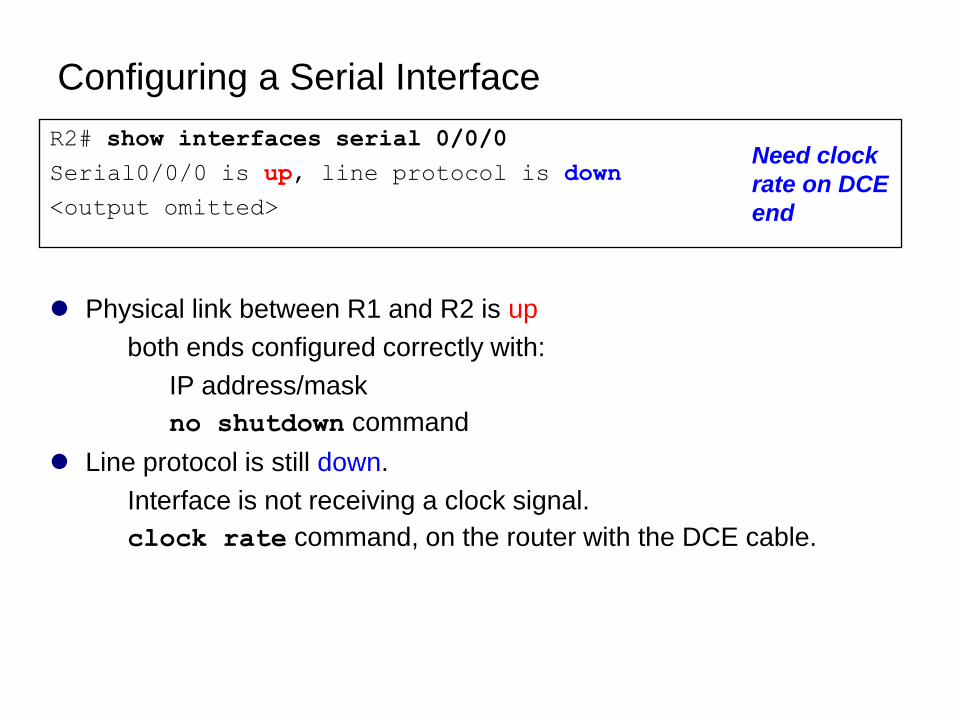
Configuring a Serial Interface
Physical link between R1 and R2 is up
both ends configured correctly with:
IP address/mask
no shutdown command
Line protocol is still down.
Interface is not receiving a clock signal.
clock rate command, on the router with the DCE cable.
R2# show interfaces serial 0/0/0
Serial0/0/0 is up, line protocol is down
<output omitted>
Need clock
rate on DCE
end
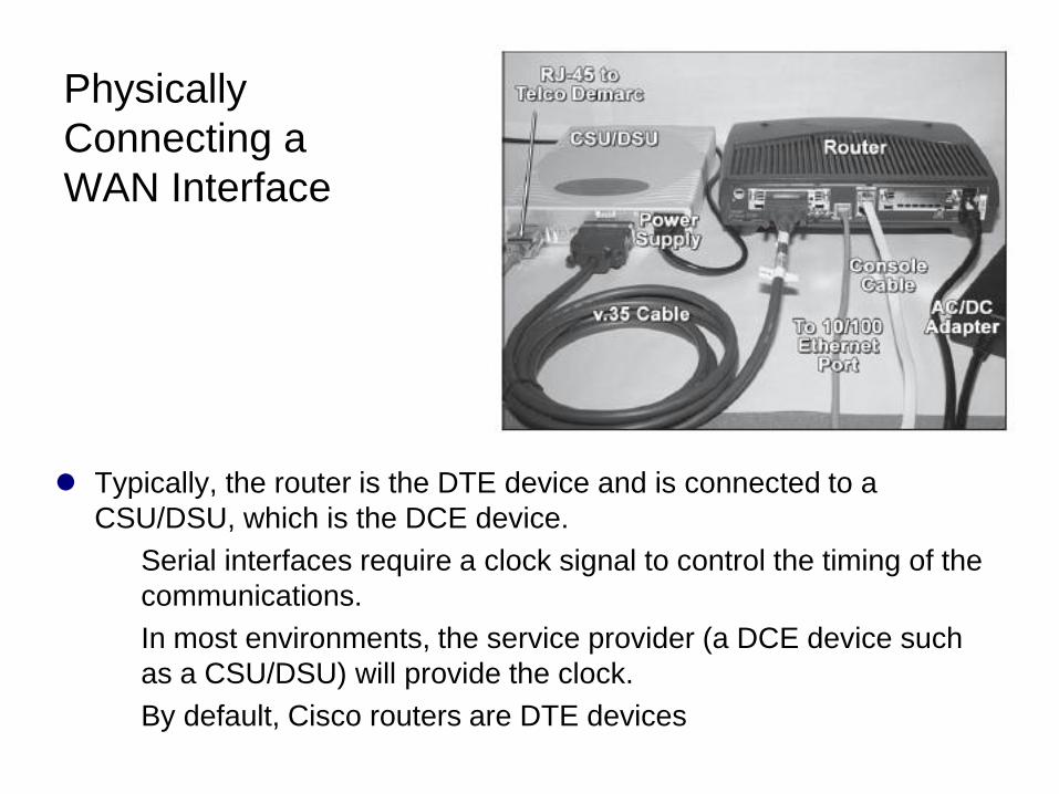
Physically
Connecting a
WAN Interface
Typically, the router is the DTE device and is connected to a
CSU/DSU, which is the DCE device.
Serial interfaces require a clock signal to control the timing of the
communications.
In most environments, the service provider (a DCE device such
as a CSU/DSU) will provide the clock.
By default, Cisco routers are DTE devices
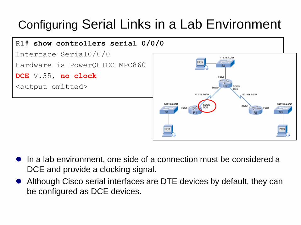
Configuring Serial Links in a Lab Environment
In a lab environment, one side of a connection must be considered a
DCE and provide a clocking signal.
Although Cisco serial interfaces are DTE devices by default, they can
be configured as DCE devices.
R1# show controllers serial 0/0/0
Interface Serial0/0/0
Hardware is PowerQUICC MPC860
DCE V.35, no clock
<output omitted>
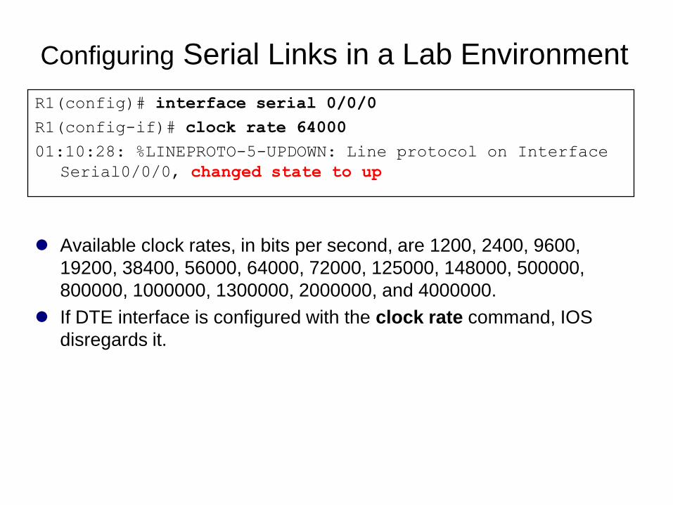
Configuring Serial Links in a Lab Environment
Available clock rates, in bits per second, are 1200, 2400, 9600,
19200, 38400, 56000, 64000, 72000, 125000, 148000, 500000,
800000, 1000000, 1300000, 2000000, and 4000000.
If DTE interface is configured with the clock rate command, IOS
disregards it.
R1(config)# interface serial 0/0/0
R1(config-if)# clock rate 64000
01:10:28: %LINEPROTO-5-UPDOWN: Line protocol on Interface
Serial0/0/0, changed state to up
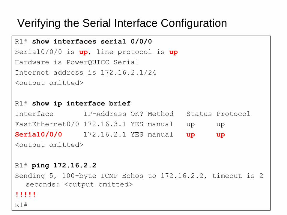
Verifying the Serial Interface Configuration
R1# show interfaces serial 0/0/0
Serial0/0/0 is up, line protocol is up
Hardware is PowerQUICC Serial
Internet address is 172.16.2.1/24
<output omitted>
R1# show ip interface brief
Interface IP-Address OK? Method Status Protocol
FastEthernet0/0 172.16.3.1 YES manual up up
Serial0/0/0 172.16.2.1 YES manual up up
<output omitted>
R1# ping 172.16.2.2
Sending 5, 100-byte ICMP Echos to 172.16.2.2, timeout is 2
seconds: <output omitted>
!!!!!
R1#

Verifying the Serial Interface Configuration
172.16.2.0/24 serial network is now in the routing table for R1
R1# show ip route
<output omitted>
Gateway of last resort is not set
172.16.0.0/24 is subnetted, 2 subnets
C 172.16.2.0 is directly connected, Serial0/0/0
C 172.16.3.0 is directly connected, FastEthernet0/0
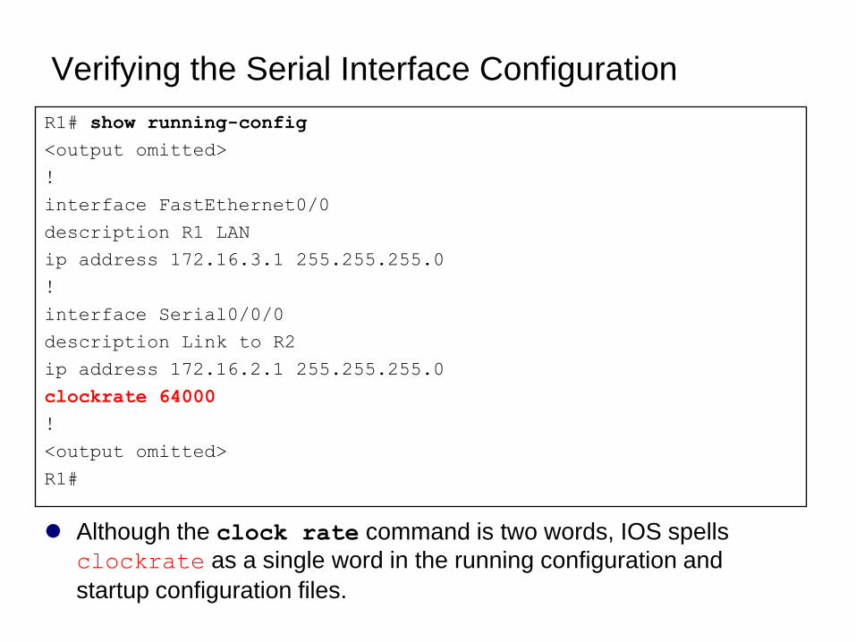
Verifying the Serial Interface Configuration
Although the clock rate command is two words, IOS spells
clockrate as a single word in the running configuration and
startup configuration files.
R1# show running-config
<output omitted>
!
interface FastEthernet0/0
description R1 LAN
ip address 172.16.3.1 255.255.255.0
!
interface Serial0/0/0
description Link to R2
ip address 172.16.2.1 255.255.255.0
clockrate 64000
!
<output omitted>
R1#
Exploring Directly
Connected Networks
Verifying Changes to the Routing Table
Devices on Directly Connected Networks
Cisco Discovery Protocol (CDP)
Using CDP for Network Discovery
Routing Table Concepts
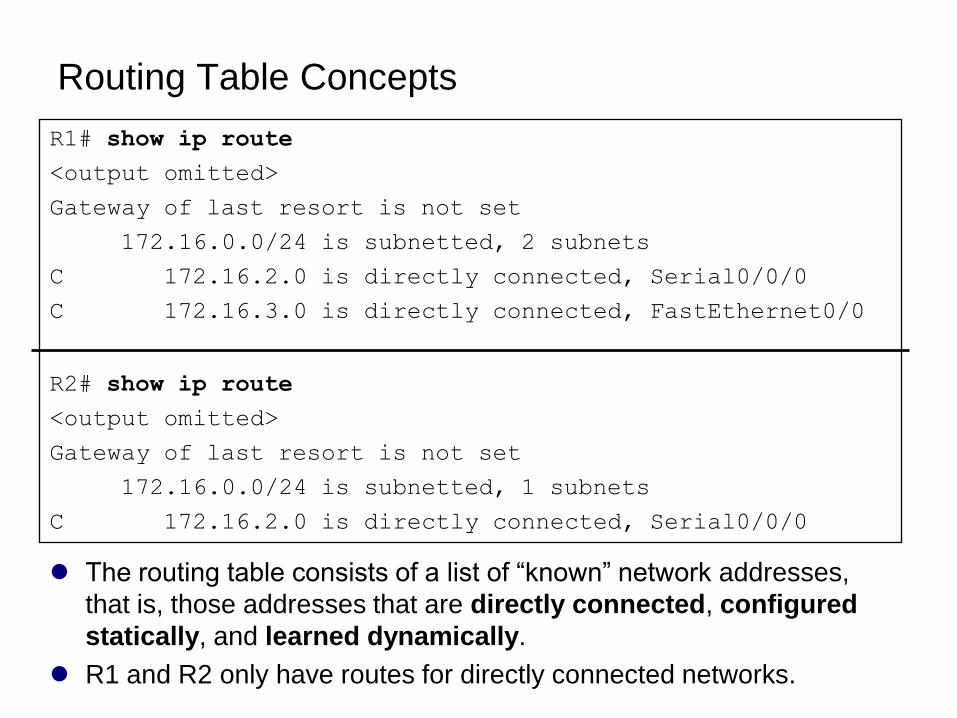
The routing table consists of a list of ―known‖ network addresses,
that is, those addresses that are directly connected, configured
statically, and learned dynamically.
R1 and R2 only have routes for directly connected networks.
R1# show ip route
<output omitted>
Gateway of last resort is not set
172.16.0.0/24 is subnetted, 2 subnets
C 172.16.2.0 is directly connected, Serial0/0/0
C 172.16.3.0 is directly connected, FastEthernet0/0
R2# show ip route
<output omitted>
Gateway of last resort is not set
172.16.0.0/24 is subnetted, 1 subnets
C 172.16.2.0 is directly connected, Serial0/0/0
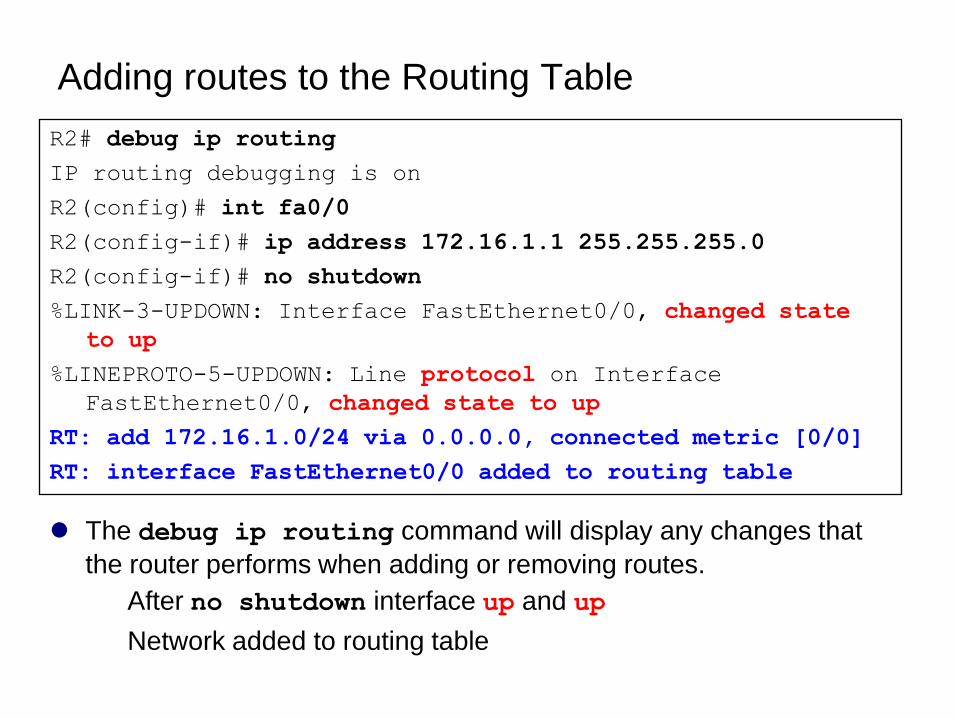
Adding routes to the Routing Table
The debug ip routing command will display any changes that
the router performs when adding or removing routes.
After no shutdown interface up and up
Network added to routing table
R2# debug ip routing
IP routing debugging is on
R2(config)# int fa0/0
R2(config-if)# ip address 172.16.1.1 255.255.255.0
R2(config-if)# no shutdown
%LINK-3-UPDOWN: Interface FastEthernet0/0, changed state
to up
%LINEPROTO-5-UPDOWN: Line protocol on Interface
FastEthernet0/0, changed state to up
RT: add 172.16.1.0/24 via 0.0.0.0, connected metric [0/0]
RT: interface FastEthernet0/0 added to routing table
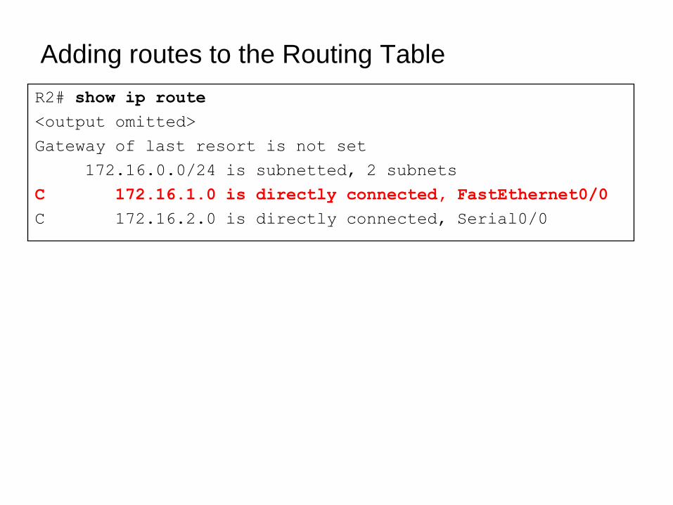
Adding routes to the Routing Table
R2# show ip route
<output omitted>
Gateway of last resort is not set
172.16.0.0/24 is subnetted, 2 subnets
C 172.16.1.0 is directly connected, FastEthernet0/0
C 172.16.2.0 is directly connected, Serial0/0
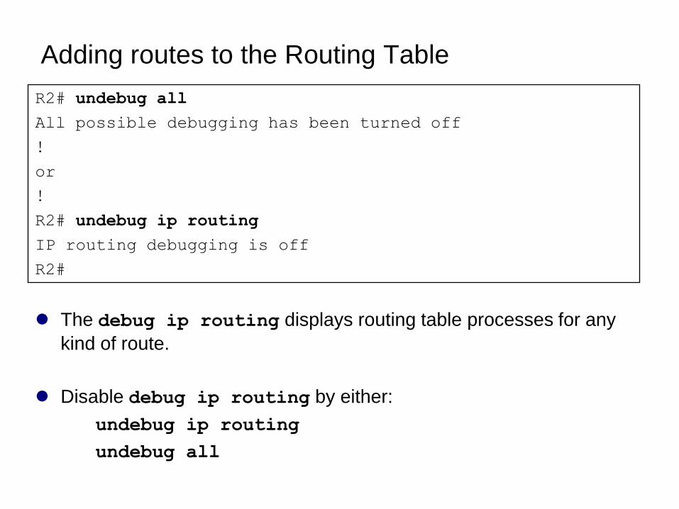
Adding routes to the Routing Table
The debug ip routing displays routing table processes for any
kind of route.
Disable debug ip routing by either:
undebug ip routing
undebug all
R2# undebug all
All possible debugging has been turned off
!
or
!
R2# undebug ip routing
IP routing debugging is off
R2#
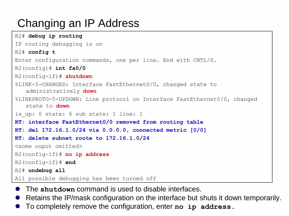
Changing an IP AddressR2# debug ip routing
IP routing debugging is on
R2# config t
Enter configuration commands, one per line. End with CNTL/Z.
R2(config)# int fa0/0
R2(config-if)# shutdown
%LINK-5-CHANGED: Interface FastEthernet0/0, changed state to
administratively down
%LINEPROTO-5-UPDOWN: Line protocol on Interface FastEthernet0/0, changed
state to down
is_up: 0 state: 6 sub state: 1 line: 1
RT: interface FastEthernet0/0 removed from routing table
RT: del 172.16.1.0/24 via 0.0.0.0, connected metric [0/0]
RT: delete subnet route to 172.16.1.0/24
<some ouput omitted>
R2(config-if)# no ip address
R2(config-if)# end
R2# undebug all
All possible debugging has been turned off
The shutdown command is used to disable interfaces.
Retains the IP/mask configuration on the interface but shuts it down temporarily.
To completely remove the configuration, enter no ip address.
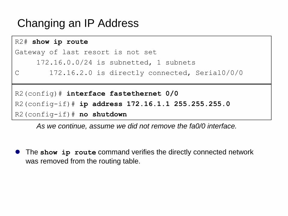
Changing an IP Address
The show ip route command verifies the directly connected network
was removed from the routing table.
R2# show ip route
Gateway of last resort is not set
172.16.0.0/24 is subnetted, 1 subnets
C 172.16.2.0 is directly connected, Serial0/0/0
R2(config)# interface fastethernet 0/0
R2(config-if)# ip address 172.16.1.1 255.255.255.0
R2(config-if)# no shutdown
As we continue, assume we did not remove the fa0/0 interface.
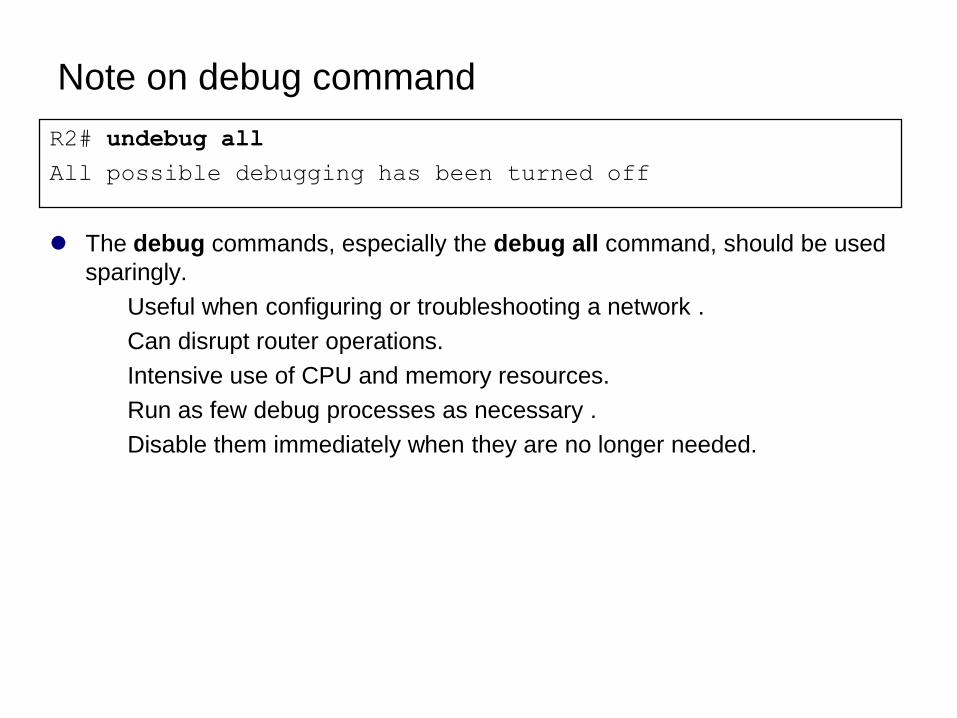
Note on debug command
The debug commands, especially the debug all command, should be used
sparingly.
Useful when configuring or troubleshooting a network .
Can disrupt router operations.
Intensive use of CPU and memory resources.
Run as few debug processes as necessary .
Disable them immediately when they are no longer needed.
R2# undebug all
All possible debugging has been turned off
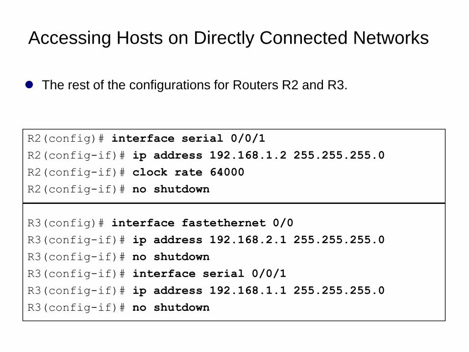
Accessing Hosts on Directly Connected Networks
The rest of the configurations for Routers R2 and R3.
R2(config)# interface serial 0/0/1
R2(config-if)# ip address 192.168.1.2 255.255.255.0
R2(config-if)# clock rate 64000
R2(config-if)# no shutdown
R3(config)# interface fastethernet 0/0
R3(config-if)# ip address 192.168.2.1 255.255.255.0
R3(config-if)# no shutdown
R3(config-if)# interface serial 0/0/1
R3(config-if)# ip address 192.168.1.1 255.255.255.0
R3(config-if)# no shutdown
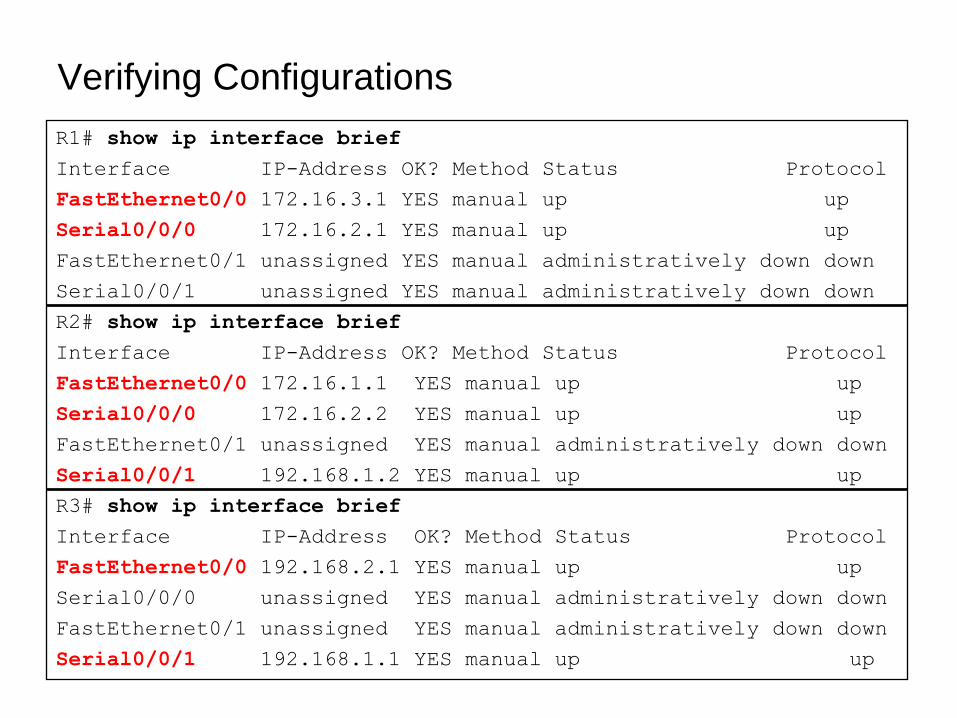
Verifying Configurations
R1# show ip interface brief
Interface IP-Address OK? Method Status Protocol
FastEthernet0/0 172.16.3.1 YES manual up up
Serial0/0/0 172.16.2.1 YES manual up up
FastEthernet0/1 unassigned YES manual administratively down down
Serial0/0/1 unassigned YES manual administratively down down
R2# show ip interface brief
Interface IP-Address OK? Method Status Protocol
FastEthernet0/0 172.16.1.1 YES manual up up
Serial0/0/0 172.16.2.2 YES manual up up
FastEthernet0/1 unassigned YES manual administratively down down
Serial0/0/1 192.168.1.2 YES manual up up
R3# show ip interface brief
Interface IP-Address OK? Method Status Protocol
FastEthernet0/0 192.168.2.1 YES manual up up
Serial0/0/0 unassigned YES manual administratively down down
FastEthernet0/1 unassigned YES manual administratively down down
Serial0/0/1 192.168.1.1 YES manual up up
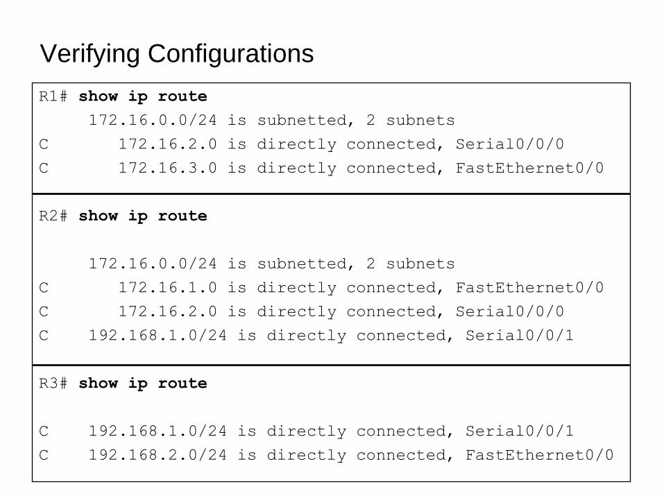
Verifying Configurations
R1# show ip route
172.16.0.0/24 is subnetted, 2 subnets
C 172.16.2.0 is directly connected, Serial0/0/0
C 172.16.3.0 is directly connected, FastEthernet0/0
R2# show ip route
172.16.0.0/24 is subnetted, 2 subnets
C 172.16.1.0 is directly connected, FastEthernet0/0
C 172.16.2.0 is directly connected, Serial0/0/0
C 192.168.1.0/24 is directly connected, Serial0/0/1
R3# show ip route
C 192.168.1.0/24 is directly connected, Serial0/0/1
C 192.168.2.0/24 is directly connected, FastEthernet0/0
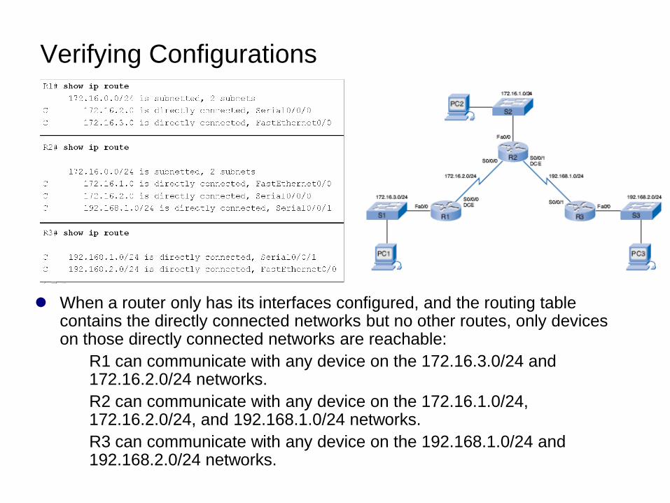
Verifying Configurations
When a router only has its interfaces configured, and the routing table contains the directly connected networks but no other routes, only devices on those directly connected networks are reachable:
R1 can communicate with any device on the 172.16.3.0/24 and 172.16.2.0/24 networks.
R2 can communicate with any device on the 172.16.1.0/24, 172.16.2.0/24, and 192.168.1.0/24 networks.
R3 can communicate with any device on the 192.168.1.0/24 and 192.168.2.0/24 networks.
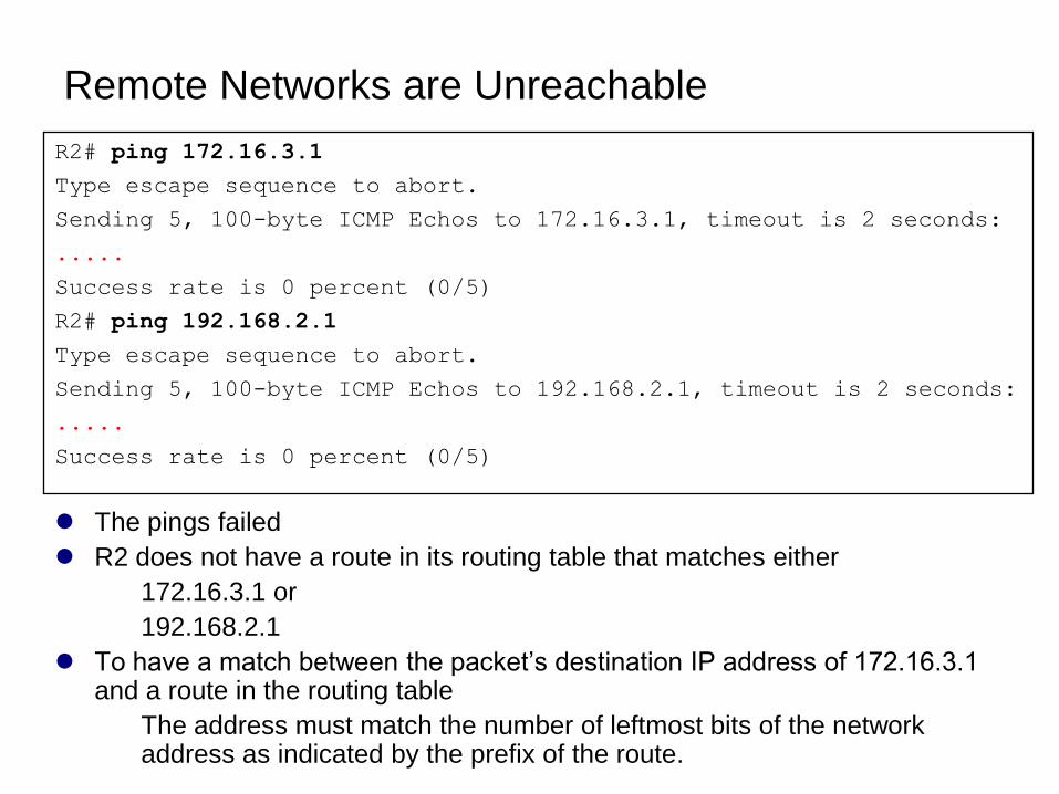
Remote Networks are Unreachable
The pings failed
R2 does not have a route in its routing table that matches either
172.16.3.1 or
192.168.2.1
To have a match between the packet’s destination IP address of 172.16.3.1 and a route in the routing table
The address must match the number of leftmost bits of the network address as indicated by the prefix of the route.
R2# ping 172.16.3.1
Type escape sequence to abort.
Sending 5, 100-byte ICMP Echos to 172.16.3.1, timeout is 2 seconds:
.....
Success rate is 0 percent (0/5)
R2# ping 192.168.2.1
Type escape sequence to abort.
Sending 5, 100-byte ICMP Echos to 192.168.2.1, timeout is 2 seconds:
.....
Success rate is 0 percent (0/5)
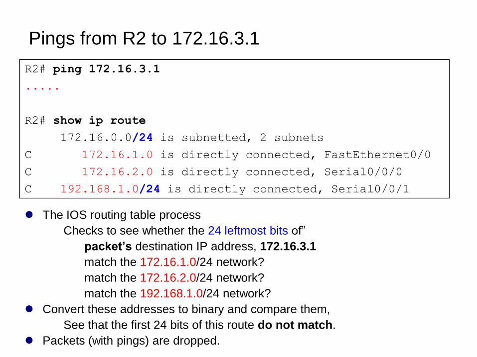
Pings from R2 to 172.16.3.1
The IOS routing table process
Checks to see whether the 24 leftmost bits of‖
packet’s destination IP address, 172.16.3.1
match the 172.16.1.0/24 network?
match the 172.16.2.0/24 network?
match the 192.168.1.0/24 network?
Convert these addresses to binary and compare them,
See that the first 24 bits of this route do not match.
Packets (with pings) are dropped.
R2# ping 172.16.3.1
.....
R2# show ip route
172.16.0.0/24 is subnetted, 2 subnets
C 172.16.1.0 is directly connected, FastEthernet0/0
C 172.16.2.0 is directly connected, Serial0/0/0
C 192.168.1.0/24 is directly connected, Serial0/0/1
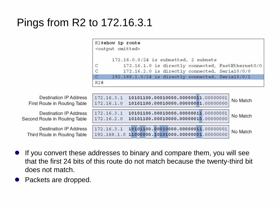
Pings from R2 to 172.16.3.1
If you convert these addresses to binary and compare them, you will see
that the first 24 bits of this route do not match because the twenty-third bit
does not match.
Packets are dropped.
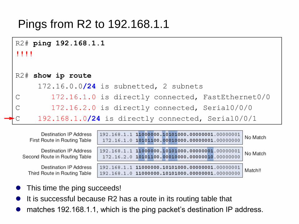
Pings from R2 to 192.168.1.1
This time the ping succeeds!
It is successful because R2 has a route in its routing table that
matches 192.168.1.1, which is the ping packet’s destination IP address.
R2# ping 192.168.1.1
!!!!
R2# show ip route
172.16.0.0/24 is subnetted, 2 subnets
C 172.16.1.0 is directly connected, FastEthernet0/0
C 172.16.2.0 is directly connected, Serial0/0/0
C 192.168.1.0/24 is directly connected, Serial0/0/1
R2# ping 192.168.1.1
!!!!
R2# show ip route
172.16.0.0/24 is subnetted, 2 subnets
C 172.16.1.0 is directly connected, FastEthernet0/0
C 172.16.2.0 is directly connected, Serial0/0/0
C 192.168.1.0/24 is directly connected, Serial0/0/1
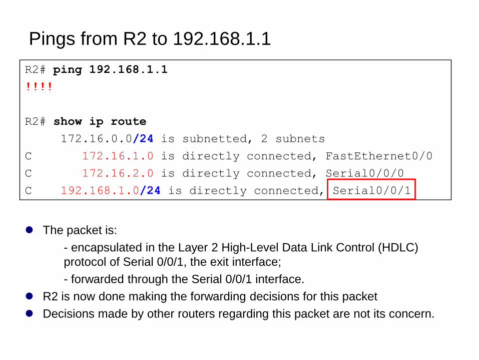
The packet is:
- encapsulated in the Layer 2 High-Level Data Link Control (HDLC)
protocol of Serial 0/0/1, the exit interface;
- forwarded through the Serial 0/0/1 interface.
R2 is now done making the forwarding decisions for this packet
Decisions made by other routers regarding this packet are not its concern.
Pings from R2 to 192.168.1.1
Cisco Discovery Protocol (CDP)
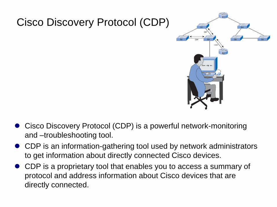
Cisco Discovery Protocol (CDP) is a powerful network-monitoring
and –troubleshooting tool.
CDP is an information-gathering tool used by network administrators
to get information about directly connected Cisco devices.
CDP is a proprietary tool that enables you to access a summary of
protocol and address information about Cisco devices that are
directly connected.
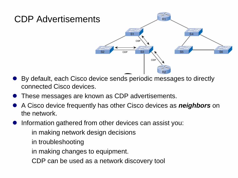
By default, each Cisco device sends periodic messages to directly
connected Cisco devices.
These messages are known as CDP advertisements.
A Cisco device frequently has other Cisco devices as neighbors on
the network.
Information gathered from other devices can assist you:
in making network design decisions
in troubleshooting
in making changes to equipment.
CDP can be used as a network discovery tool
CDP Advertisements
Layer 3 Neighbors
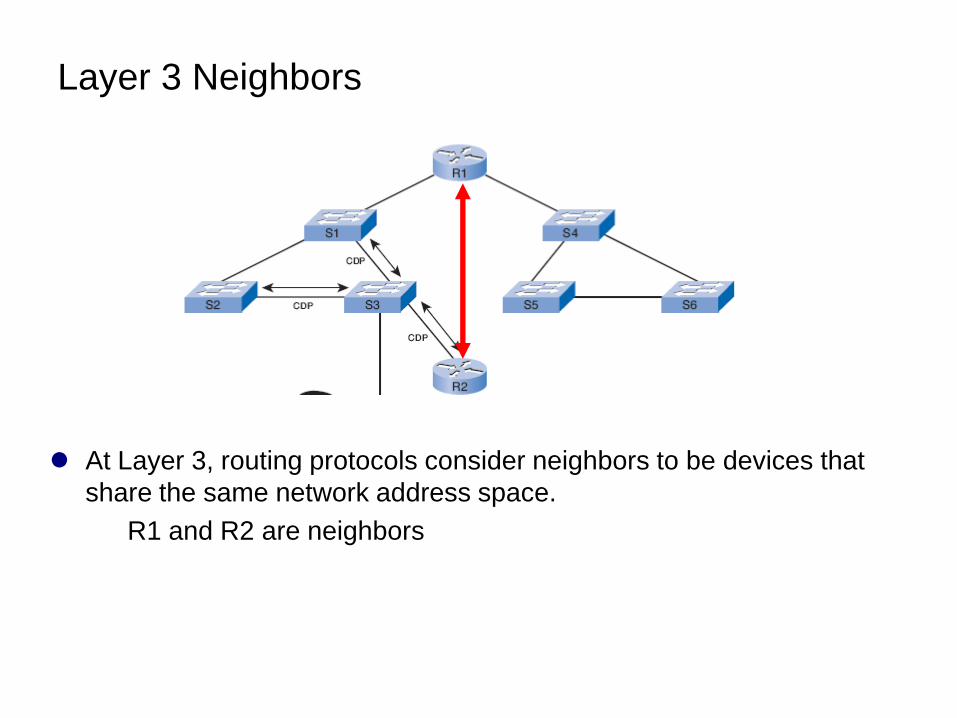
At Layer 3, routing protocols consider neighbors to be devices that
share the same network address space.
R1 and R2 are neighbors
Layer 2 Neighbors
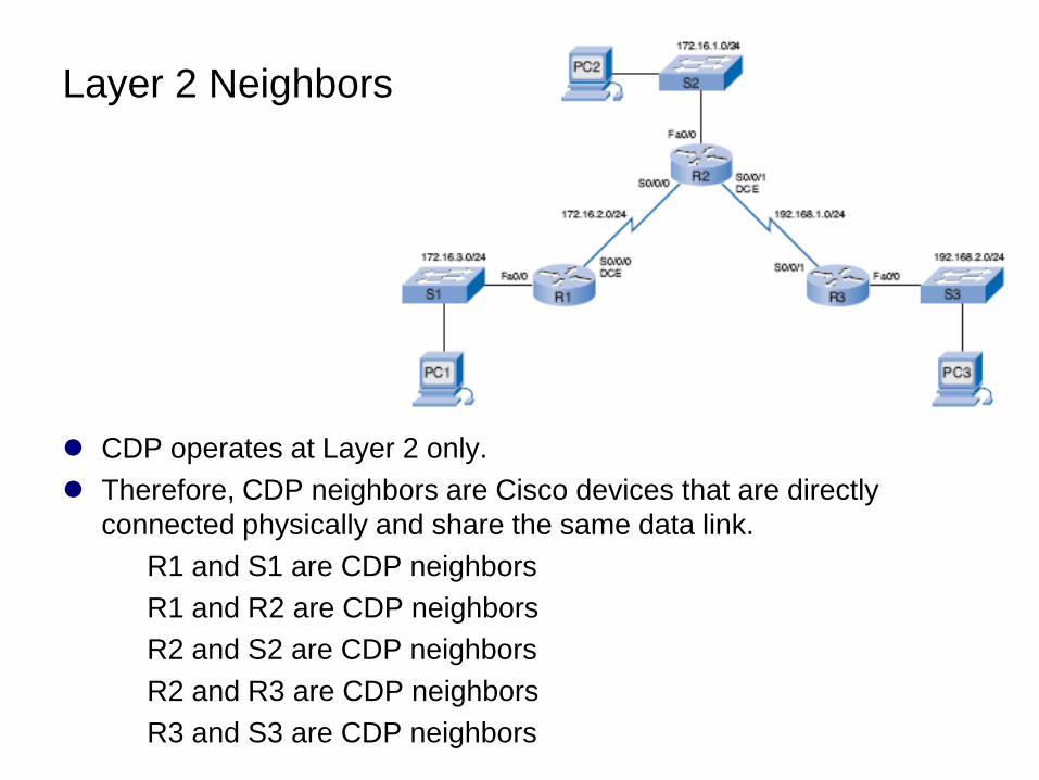
CDP operates at Layer 2 only.
Therefore, CDP neighbors are Cisco devices that are directly
connected physically and share the same data link.
R1 and S1 are CDP neighbors
R1 and R2 are CDP neighbors
R2 and S2 are CDP neighbors
R2 and R3 are CDP neighbors
R3 and S3 are CDP neighbors
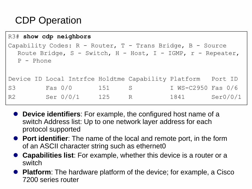
CDP Operation
Device identifiers: For example, the configured host name of a switch Address list: Up to one network layer address for each protocol supported
Port identifier: The name of the local and remote port, in the form of an ASCII character string such as ethernet0
Capabilities list: For example, whether this device is a router or a switch
Platform: The hardware platform of the device; for example, a Cisco 7200 series router
R3# show cdp neighbors
Capability Codes: R - Router, T - Trans Bridge, B - Source
Route Bridge, S - Switch, H - Host, I - IGMP, r - Repeater,
P - Phone
Device ID Local Intrfce Holdtme Capability Platform Port ID
S3 Fas 0/0 151 S I WS-C2950 Fas 0/6
R2 Ser 0/0/1 125 R 1841 Ser0/0/1
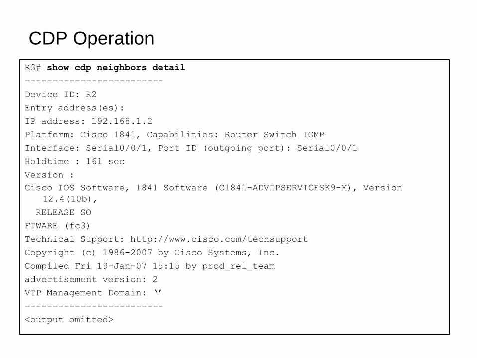
R3# show cdp neighbors detail
-------------------------
Device ID: R2
Entry address(es):
IP address: 192.168.1.2
Platform: Cisco 1841, Capabilities: Router Switch IGMP
Interface: Serial0/0/1, Port ID (outgoing port): Serial0/0/1
Holdtime : 161 sec
Version :
Cisco IOS Software, 1841 Software (C1841-ADVIPSERVICESK9-M), Version
12.4(10b),
RELEASE SO
FTWARE (fc3)
Technical Support: http://www.cisco.com/techsupport
Copyright (c) 1986-2007 by Cisco Systems, Inc.
Compiled Fri 19-Jan-07 15:15 by prod_rel_team
advertisement version: 2
VTP Management Domain: ‘’
-------------------------
<output omitted>
CDP Operation
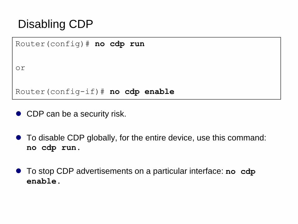
Disabling CDP
CDP can be a security risk.
To disable CDP globally, for the entire device, use this command: no cdp run.
To stop CDP advertisements on a particular interface: no cdp
enable.
Router(config)# no cdp run
or
Router(config-if)# no cdp enable
Static Routes with
―Next-Hop‖ Addresses
ip route command
Configuring Static Routes
Routing Table Principles
Resolving to an Exit Interface with a Recursive Lookup
Purpose and Command Syntax
of the ip route Command
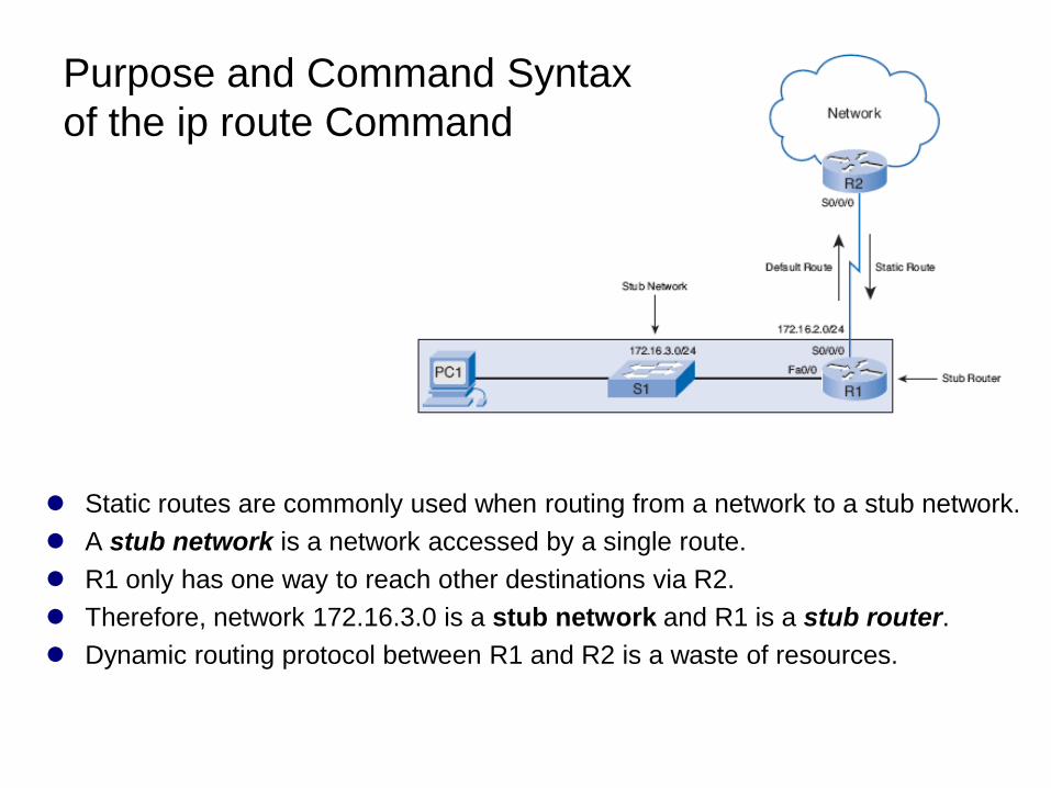
Static routes are commonly used when routing from a network to a stub network.
A stub network is a network accessed by a single route.
R1 only has one way to reach other destinations via R2.
Therefore, network 172.16.3.0 is a stub network and R1 is a stub router.
Dynamic routing protocol between R1 and R2 is a waste of resources.
ip route Command
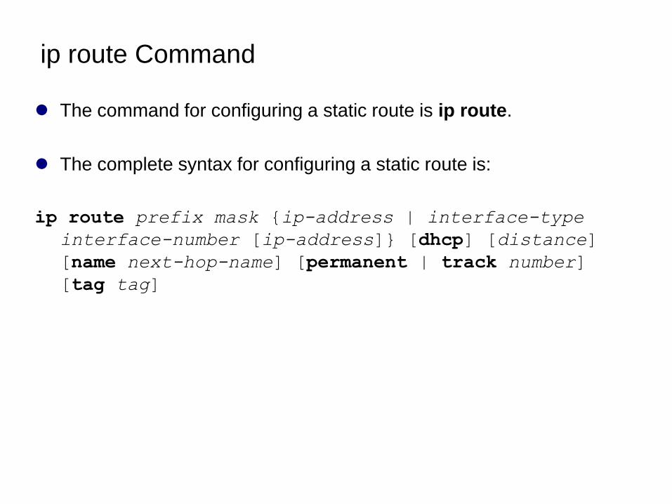
The command for configuring a static route is ip route.
The complete syntax for configuring a static route is:
ip route prefix mask {ip-address | interface-type
interface-number [ip-address]} [dhcp] [distance]
[name next-hop-name] [permanent | track number]
[tag tag]
ip route Command
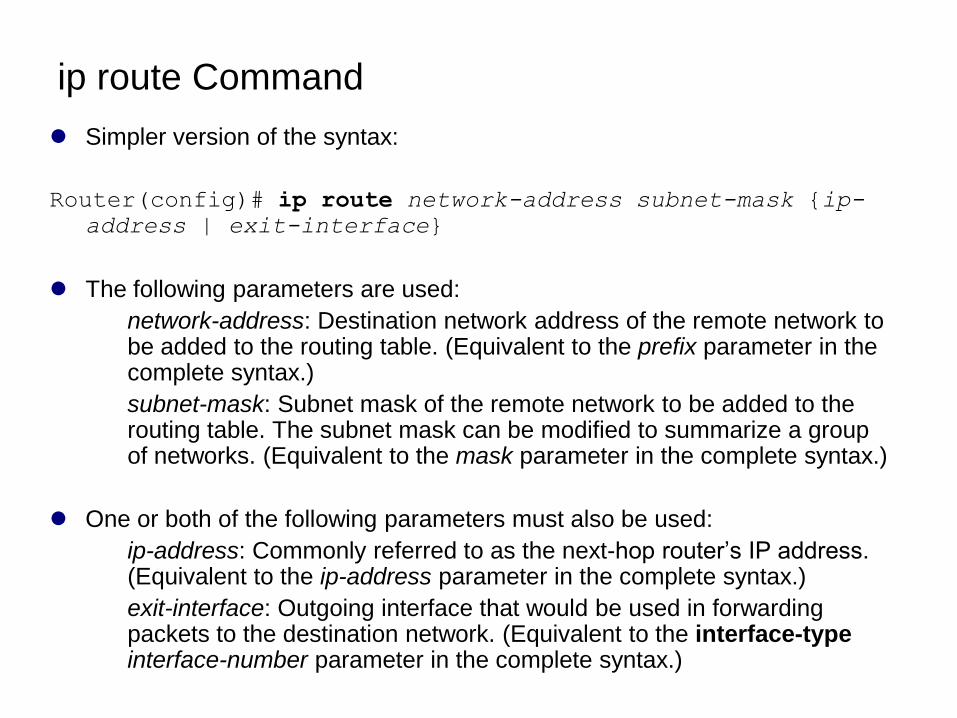
Simpler version of the syntax:
Router(config)# ip route network-address subnet-mask {ip-
address | exit-interface}
The following parameters are used:
network-address: Destination network address of the remote network to be added to the routing table. (Equivalent to the prefix parameter in the complete syntax.)
subnet-mask: Subnet mask of the remote network to be added to the routing table. The subnet mask can be modified to summarize a group of networks. (Equivalent to the mask parameter in the complete syntax.)
One or both of the following parameters must also be used:
ip-address: Commonly referred to as the next-hop router’s IP address. (Equivalent to the ip-address parameter in the complete syntax.)
exit-interface: Outgoing interface that would be used in forwarding packets to the destination network. (Equivalent to the interface-type interface-number parameter in the complete syntax.)
ip route Command
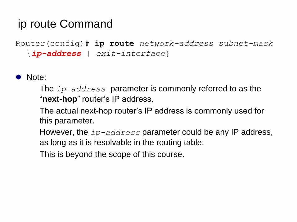
Router(config)# ip route network-address subnet-mask
{ip-address | exit-interface}
Note:
The ip-address parameter is commonly referred to as the
―next-hop‖ router’s IP address.
The actual next-hop router’s IP address is commonly used for
this parameter.
However, the ip-address parameter could be any IP address,
as long as it is resolvable in the routing table.
This is beyond the scope of this course.
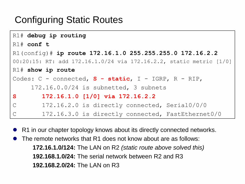
Configuring Static Routes
R1 in our chapter topology knows about its directly connected networks.
The remote networks that R1 does not know about are as follows:
172.16.1.0/124: The LAN on R2 (static route above solved this)
192.168.1.0/24: The serial network between R2 and R3
192.168.2.0/24: The LAN on R3
R1# debug ip routing
R1# conf t
R1(config)# ip route 172.16.1.0 255.255.255.0 172.16.2.2
00:20:15: RT: add 172.16.1.0/24 via 172.16.2.2, static metric [1/0]
R1# show ip route
Codes: C - connected, S - static, I - IGRP, R - RIP,
172.16.0.0/24 is subnetted, 3 subnets
S 172.16.1.0 [1/0] via 172.16.2.2
C 172.16.2.0 is directly connected, Serial0/0/0
C 172.16.3.0 is directly connected, FastEthernet0/0
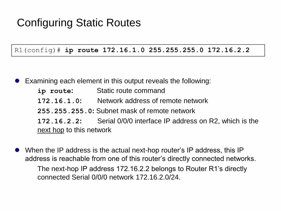
Configuring Static Routes
Examining each element in this output reveals the following:
ip route: Static route command
172.16.1.0: Network address of remote network
255.255.255.0: Subnet mask of remote network
172.16.2.2: Serial 0/0/0 interface IP address on R2, which is the
next hop to this network
When the IP address is the actual next-hop router’s IP address, this IP
address is reachable from one of this router’s directly connected networks.
The next-hop IP address 172.16.2.2 belongs to Router R1’s directly
connected Serial 0/0/0 network 172.16.2.0/24.
R1(config)# ip route 172.16.1.0 255.255.255.0 172.16.2.2
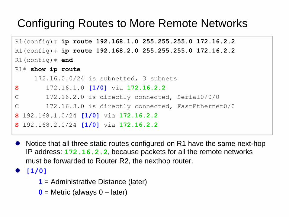
Configuring Routes to More Remote Networks
Notice that all three static routes configured on R1 have the same next-hop IP address: 172.16.2.2, because packets for all the remote networks
must be forwarded to Router R2, the nexthop router.
[1/0]
1 = Administrative Distance (later)
0 = Metric (always 0 – later)
R1(config)# ip route 192.168.1.0 255.255.255.0 172.16.2.2
R1(config)# ip route 192.168.2.0 255.255.255.0 172.16.2.2
R1(config)# end
R1# show ip route
172.16.0.0/24 is subnetted, 3 subnets
S 172.16.1.0 [1/0] via 172.16.2.2
C 172.16.2.0 is directly connected, Serial0/0/0
C 172.16.3.0 is directly connected, FastEthernet0/0
S 192.168.1.0/24 [1/0] via 172.16.2.2
S 192.168.2.0/24 [1/0] via 172.16.2.2
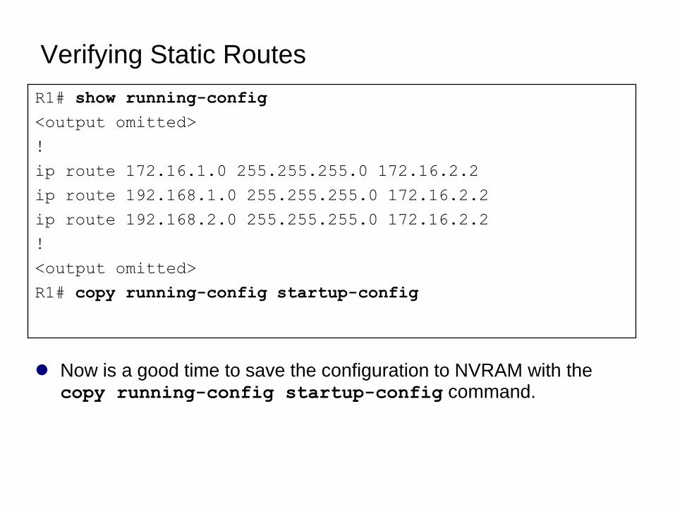
Verifying Static Routes
Now is a good time to save the configuration to NVRAM with the copy running-config startup-config command.
R1# show running-config
<output omitted>
!
ip route 172.16.1.0 255.255.255.0 172.16.2.2
ip route 192.168.1.0 255.255.255.0 172.16.2.2
ip route 192.168.2.0 255.255.255.0 172.16.2.2
!
<output omitted>
R1# copy running-config startup-config
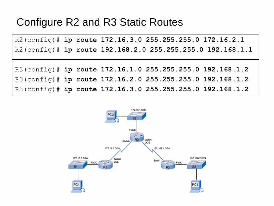
Configure R2 and R3 Static Routes
R2(config)# ip route 172.16.3.0 255.255.255.0 172.16.2.1
R2(config)# ip route 192.168.2.0 255.255.255.0 192.168.1.1
R3(config)# ip route 172.16.1.0 255.255.255.0 192.168.1.2
R3(config)# ip route 172.16.2.0 255.255.255.0 192.168.1.2
R3(config)# ip route 172.16.3.0 255.255.255.0 192.168.1.2
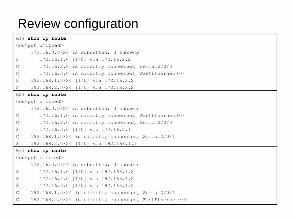
R1# show ip route
<output omitted>
172.16.0.0/24 is subnetted, 3 subnets
S 172.16.1.0 [1/0] via 172.16.2.2
C 172.16.2.0 is directly connected, Serial0/0/0
C 172.16.3.0 is directly connected, FastEthernet0/0
S 192.168.1.0/24 [1/0] via 172.16.2.2
S 192.168.2.0/24 [1/0] via 172.16.2.2
R2# show ip route
<output omitted>
172.16.0.0/24 is subnetted, 3 subnets
C 172.16.1.0 is directly connected, FastEthernet0/0
C 172.16.2.0 is directly connected, Serial0/0/0
S 172.16.3.0 [1/0] via 172.16.2.1
C 192.168.1.0/24 is directly connected, Serial0/0/1
S 192.168.2.0/24 [1/0] via 192.168.1.1
R3# show ip route
<output omitted>
172.16.0.0/24 is subnetted, 3 subnets
S 172.16.1.0 [1/0] via 192.168.1.2
S 172.16.2.0 [1/0] via 192.168.1.2
S 172.16.3.0 [1/0] via 192.168.1.2
C 192.168.1.0/24 is directly connected, Serial0/0/1
C 192.168.2.0/24 is directly connected, FastEthernet0/0
Review configuration
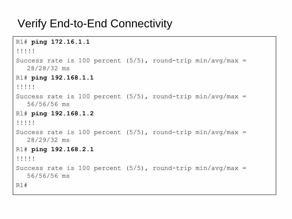
Verify End-to-End Connectivity
R1# ping 172.16.1.1
!!!!!
Success rate is 100 percent (5/5), round-trip min/avg/max =
28/28/32 ms
R1# ping 192.168.1.1
!!!!!
Success rate is 100 percent (5/5), round-trip min/avg/max =
56/56/56 ms
R1# ping 192.168.1.2
!!!!!
Success rate is 100 percent (5/5), round-trip min/avg/max =
28/29/32 ms
R1# ping 192.168.2.1
!!!!!
Success rate is 100 percent (5/5), round-trip min/avg/max =
56/56/56 ms
R1#
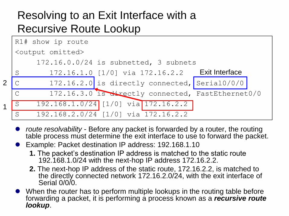
Resolving to an Exit Interface with a
Recursive Route Lookup
route resolvability - Before any packet is forwarded by a router, the routing table process must determine the exit interface to use to forward the packet.
Example: Packet destination IP address: 192.168.1.10
1. The packet’s destination IP address is matched to the static route 192.168.1.0/24 with the next-hop IP address 172.16.2.2.
2. The next-hop IP address of the static route, 172.16.2.2, is matched to the directly connected network 172.16.2.0/24, with the exit interface of Serial 0/0/0.
When the router has to perform multiple lookups in the routing table before forwarding a packet, it is performing a process known as a recursive route lookup.
R1# show ip route
<output omitted>
172.16.0.0/24 is subnetted, 3 subnets
S 172.16.1.0 [1/0] via 172.16.2.2
C 172.16.2.0 is directly connected, Serial0/0/0
C 172.16.3.0 is directly connected, FastEthernet0/0
S 192.168.1.0/24 [1/0] via 172.16.2.2
S 192.168.2.0/24 [1/0] via 172.16.2.21
2
Exit Interface
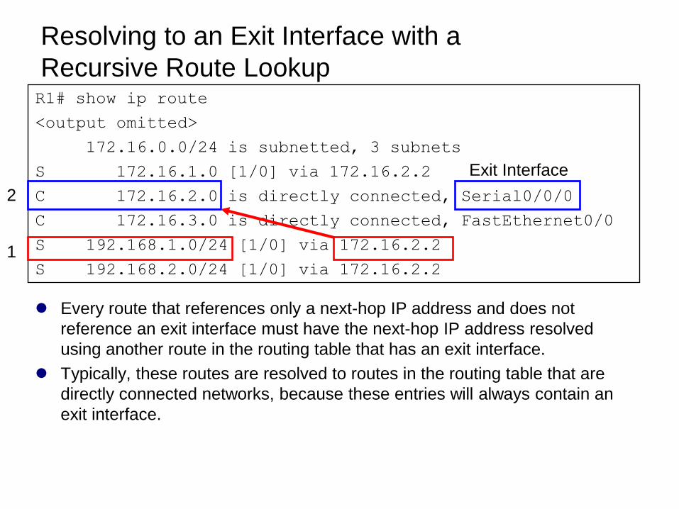
Every route that references only a next-hop IP address and does not
reference an exit interface must have the next-hop IP address resolved
using another route in the routing table that has an exit interface.
Typically, these routes are resolved to routes in the routing table that are
directly connected networks, because these entries will always contain an
exit interface.
R1# show ip route
<output omitted>
172.16.0.0/24 is subnetted, 3 subnets
S 172.16.1.0 [1/0] via 172.16.2.2
C 172.16.2.0 is directly connected, Serial0/0/0
C 172.16.3.0 is directly connected, FastEthernet0/0
S 192.168.1.0/24 [1/0] via 172.16.2.2
S 192.168.2.0/24 [1/0] via 172.16.2.21
2
Exit Interface
Resolving to an Exit Interface with a
Recursive Route Lookup
Exit Interface Is Down
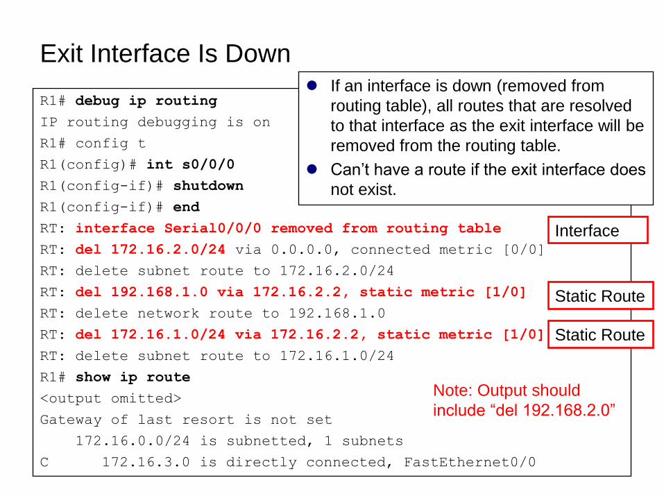
R1# debug ip routing
IP routing debugging is on
R1# config t
R1(config)# int s0/0/0
R1(config-if)# shutdown
R1(config-if)# end
RT: interface Serial0/0/0 removed from routing table
RT: del 172.16.2.0/24 via 0.0.0.0, connected metric [0/0]
RT: delete subnet route to 172.16.2.0/24
RT: del 192.168.1.0 via 172.16.2.2, static metric [1/0]
RT: delete network route to 192.168.1.0
RT: del 172.16.1.0/24 via 172.16.2.2, static metric [1/0]
RT: delete subnet route to 172.16.1.0/24
R1# show ip route
<output omitted>
Gateway of last resort is not set
172.16.0.0/24 is subnetted, 1 subnets
C 172.16.3.0 is directly connected, FastEthernet0/0
If an interface is down (removed from
routing table), all routes that are resolved
to that interface as the exit interface will be
removed from the routing table.
Can’t have a route if the exit interface does
not exist.
Interface
Static Route
Static Route
Note: Output should
include ―del 192.168.2.0‖
Interface comes back up
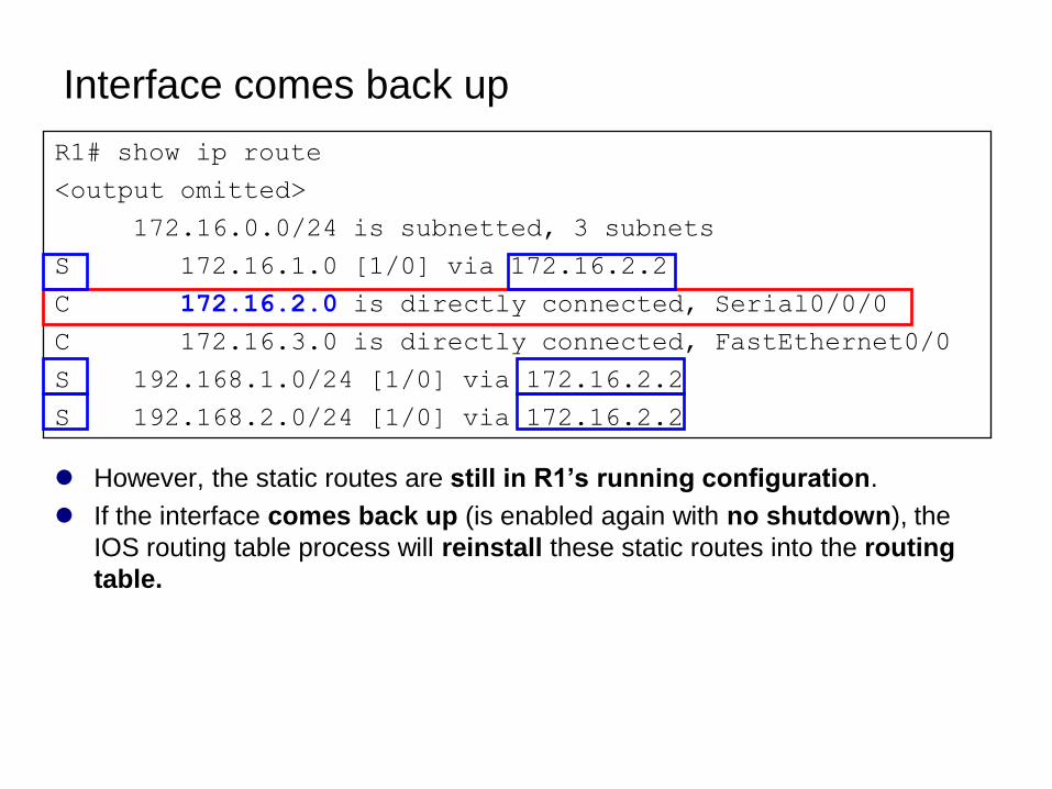
However, the static routes are still in R1’s running configuration.
If the interface comes back up (is enabled again with no shutdown), the
IOS routing table process will reinstall these static routes into the routing
table.
R1# show ip route
<output omitted>
172.16.0.0/24 is subnetted, 3 subnets
S 172.16.1.0 [1/0] via 172.16.2.2
C 172.16.2.0 is directly connected, Serial0/0/0
C 172.16.3.0 is directly connected, FastEthernet0/0
S 192.168.1.0/24 [1/0] via 172.16.2.2
S 192.168.2.0/24 [1/0] via 172.16.2.2
Static Routes with
Exit Interfaces
Configuring a Static Route with an Exit Interfaces
Static Routes and Point-to-Point Networks
Modifying Static Routes
Verifying the Static Route Configuration
Static Routes - Ethernet Interface
Static Routes with Exit Interfaces
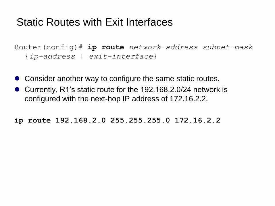
Router(config)# ip route network-address subnet-mask
{ip-address | exit-interface}
Consider another way to configure the same static routes.
Currently, R1’s static route for the 192.168.2.0/24 network is
configured with the next-hop IP address of 172.16.2.2.
ip route 192.168.2.0 255.255.255.0 172.16.2.2
Static Route and an Exit Interface
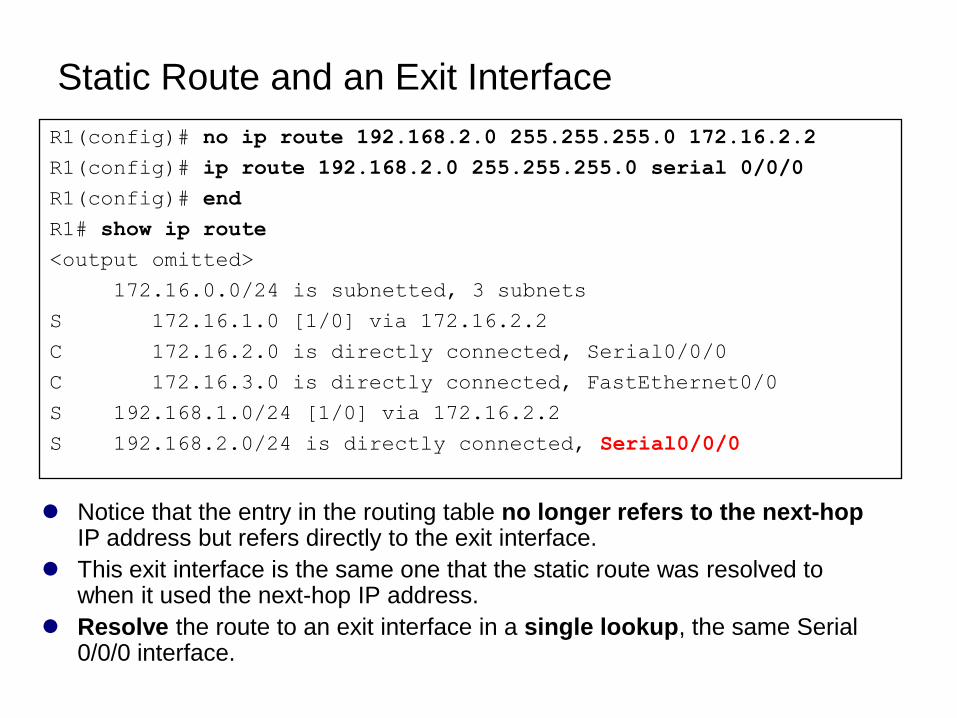
Notice that the entry in the routing table no longer refers to the next-hopIP address but refers directly to the exit interface.
This exit interface is the same one that the static route was resolved to when it used the next-hop IP address.
Resolve the route to an exit interface in a single lookup, the same Serial 0/0/0 interface.
R1(config)# no ip route 192.168.2.0 255.255.255.0 172.16.2.2
R1(config)# ip route 192.168.2.0 255.255.255.0 serial 0/0/0
R1(config)# end
R1# show ip route
<output omitted>
172.16.0.0/24 is subnetted, 3 subnets
S 172.16.1.0 [1/0] via 172.16.2.2
C 172.16.2.0 is directly connected, Serial0/0/0
C 172.16.3.0 is directly connected, FastEthernet0/0
S 192.168.1.0/24 [1/0] via 172.16.2.2
S 192.168.2.0/24 is directly connected, Serial0/0/0
Important note
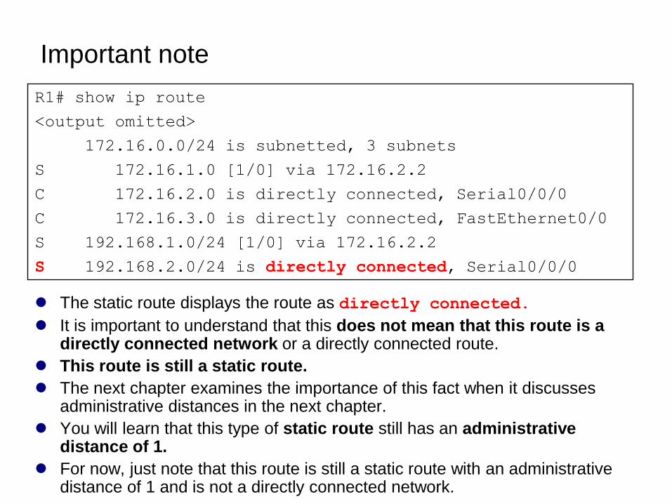
The static route displays the route as directly connected.
It is important to understand that this does not mean that this route is a directly connected network or a directly connected route.
This route is still a static route.
The next chapter examines the importance of this fact when it discusses administrative distances in the next chapter.
You will learn that this type of static route still has an administrative distance of 1.
For now, just note that this route is still a static route with an administrative distance of 1 and is not a directly connected network.
R1# show ip route
<output omitted>
172.16.0.0/24 is subnetted, 3 subnets
S 172.16.1.0 [1/0] via 172.16.2.2
C 172.16.2.0 is directly connected, Serial0/0/0
C 172.16.3.0 is directly connected, FastEthernet0/0
S 192.168.1.0/24 [1/0] via 172.16.2.2
S 192.168.2.0/24 is directly connected, Serial0/0/0
Static Routes and Point-to-Point Networks
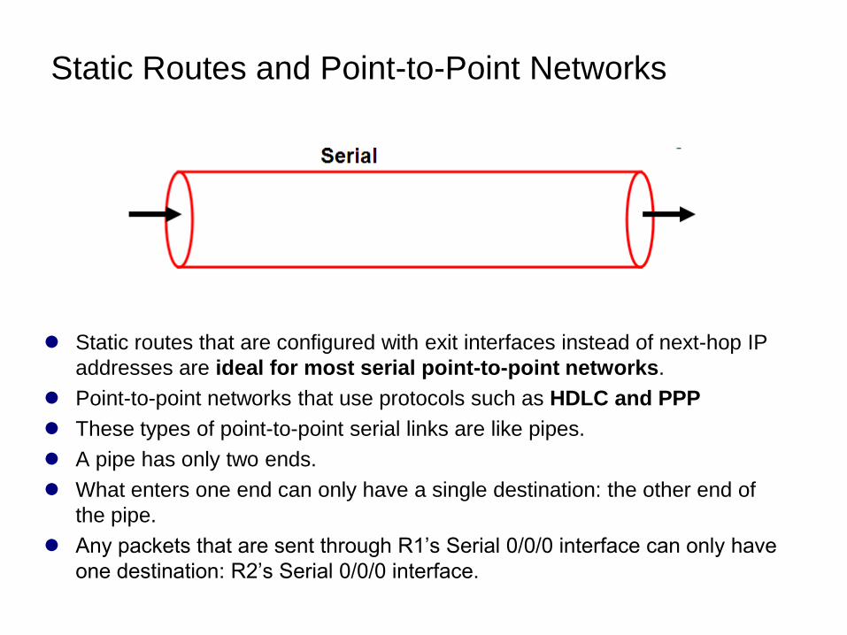
Static routes that are configured with exit interfaces instead of next-hop IP
addresses are ideal for most serial point-to-point networks.
Point-to-point networks that use protocols such as HDLC and PPP
These types of point-to-point serial links are like pipes.
A pipe has only two ends.
What enters one end can only have a single destination: the other end of
the pipe.
Any packets that are sent through R1’s Serial 0/0/0 interface can only have
one destination: R2’s Serial 0/0/0 interface.
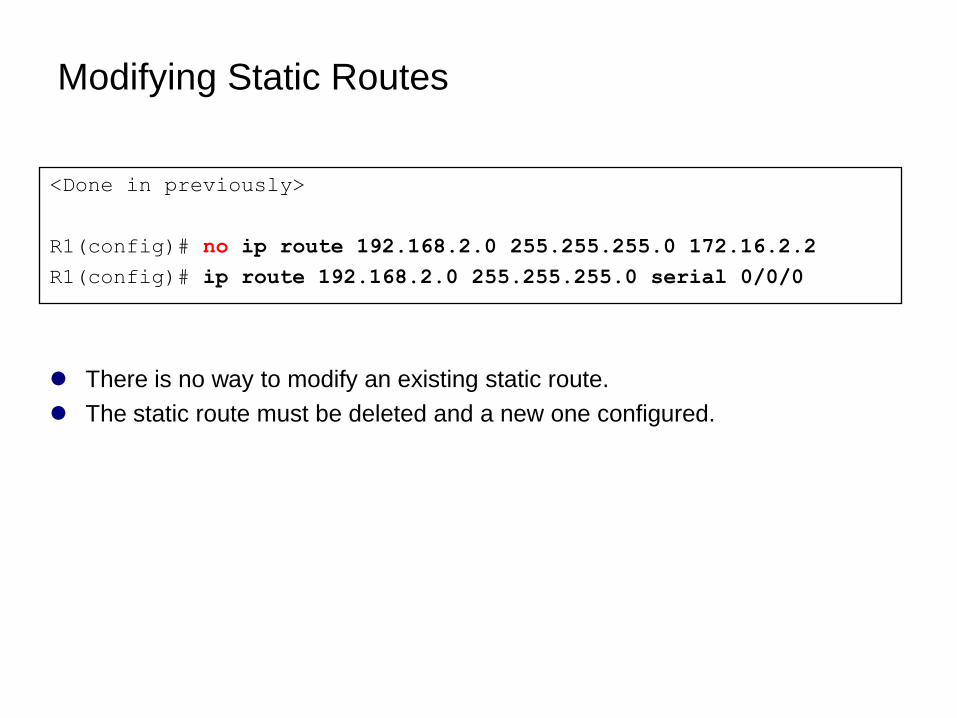
Modifying Static Routes
There is no way to modify an existing static route.
The static route must be deleted and a new one configured.
<Done in previously>
R1(config)# no ip route 192.168.2.0 255.255.255.0 172.16.2.2
R1(config)# ip route 192.168.2.0 255.255.255.0 serial 0/0/0
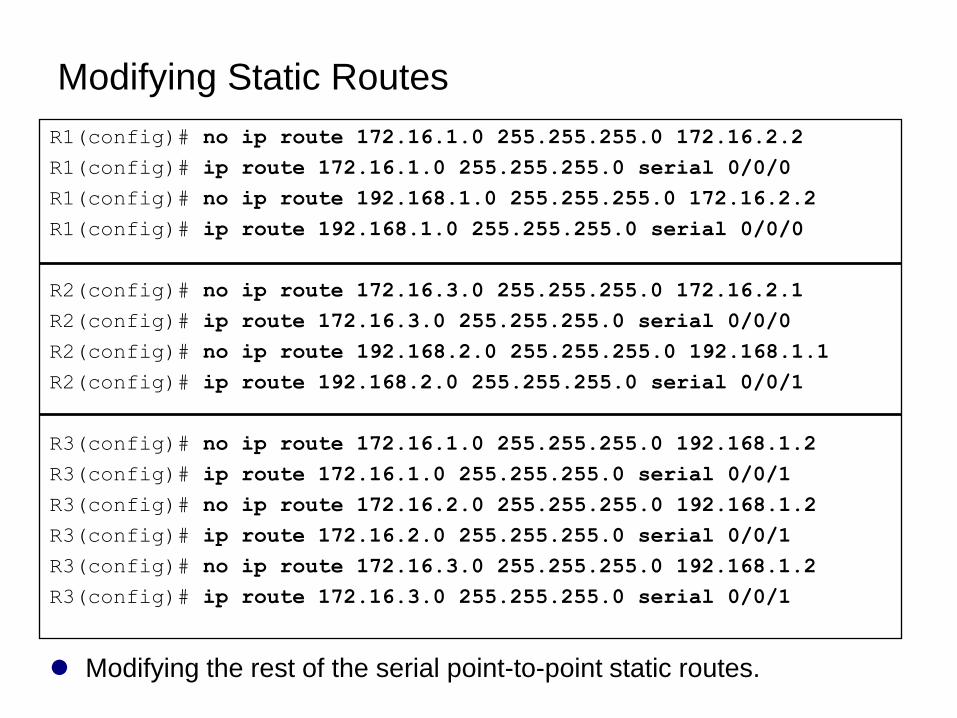
Modifying Static Routes
Modifying the rest of the serial point-to-point static routes.
R1(config)# no ip route 172.16.1.0 255.255.255.0 172.16.2.2
R1(config)# ip route 172.16.1.0 255.255.255.0 serial 0/0/0
R1(config)# no ip route 192.168.1.0 255.255.255.0 172.16.2.2
R1(config)# ip route 192.168.1.0 255.255.255.0 serial 0/0/0
R2(config)# no ip route 172.16.3.0 255.255.255.0 172.16.2.1
R2(config)# ip route 172.16.3.0 255.255.255.0 serial 0/0/0
R2(config)# no ip route 192.168.2.0 255.255.255.0 192.168.1.1
R2(config)# ip route 192.168.2.0 255.255.255.0 serial 0/0/1
R3(config)# no ip route 172.16.1.0 255.255.255.0 192.168.1.2
R3(config)# ip route 172.16.1.0 255.255.255.0 serial 0/0/1
R3(config)# no ip route 172.16.2.0 255.255.255.0 192.168.1.2
R3(config)# ip route 172.16.2.0 255.255.255.0 serial 0/0/1
R3(config)# no ip route 172.16.3.0 255.255.255.0 192.168.1.2
R3(config)# ip route 172.16.3.0 255.255.255.0 serial 0/0/1
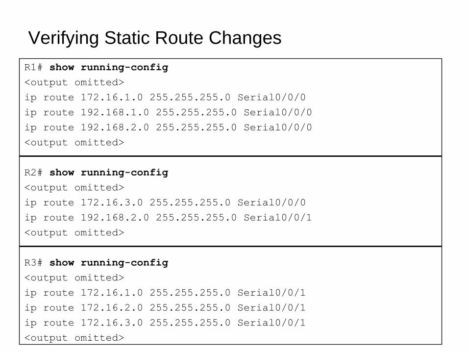
Verifying Static Route Changes
R1# show running-config
<output omitted>
ip route 172.16.1.0 255.255.255.0 Serial0/0/0
ip route 192.168.1.0 255.255.255.0 Serial0/0/0
ip route 192.168.2.0 255.255.255.0 Serial0/0/0
<output omitted>
R2# show running-config
<output omitted>
ip route 172.16.3.0 255.255.255.0 Serial0/0/0
ip route 192.168.2.0 255.255.255.0 Serial0/0/1
<output omitted>
R3# show running-config
<output omitted>
ip route 172.16.1.0 255.255.255.0 Serial0/0/1
ip route 172.16.2.0 255.255.255.0 Serial0/0/1
ip route 172.16.3.0 255.255.255.0 Serial0/0/1
<output omitted>
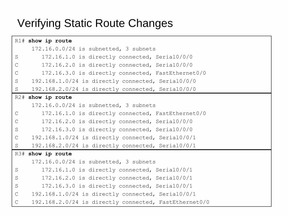
R1# show ip route
172.16.0.0/24 is subnetted, 3 subnets
S 172.16.1.0 is directly connected, Serial0/0/0
C 172.16.2.0 is directly connected, Serial0/0/0
C 172.16.3.0 is directly connected, FastEthernet0/0
S 192.168.1.0/24 is directly connected, Serial0/0/0
S 192.168.2.0/24 is directly connected, Serial0/0/0
R2# show ip route
172.16.0.0/24 is subnetted, 3 subnets
C 172.16.1.0 is directly connected, FastEthernet0/0
C 172.16.2.0 is directly connected, Serial0/0/0
S 172.16.3.0 is directly connected, Serial0/0/0
C 192.168.1.0/24 is directly connected, Serial0/0/1
S 192.168.2.0/24 is directly connected, Serial0/0/1
R3# show ip route
172.16.0.0/24 is subnetted, 3 subnets
S 172.16.1.0 is directly connected, Serial0/0/1
S 172.16.2.0 is directly connected, Serial0/0/1
S 172.16.3.0 is directly connected, Serial0/0/1
C 192.168.1.0/24 is directly connected, Serial0/0/1
C 192.168.2.0/24 is directly connected, FastEthernet0/0
Verifying Static Route Changes
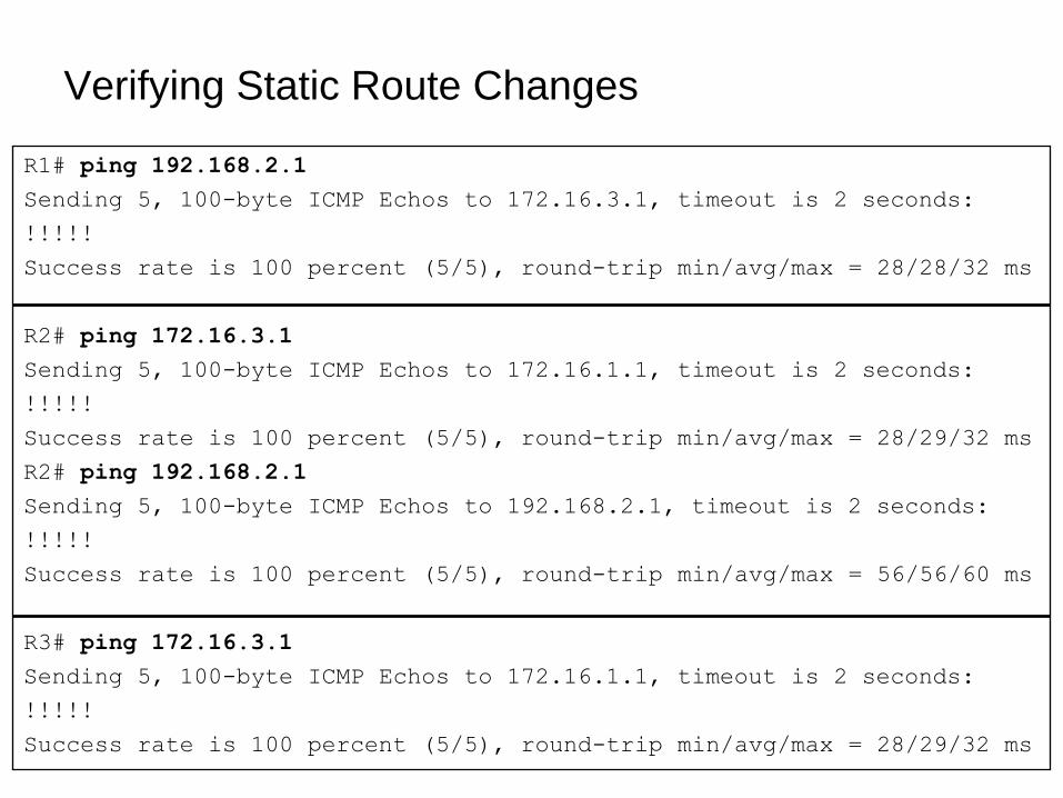
Verifying Static Route Changes
R1# ping 192.168.2.1
Sending 5, 100-byte ICMP Echos to 172.16.3.1, timeout is 2 seconds:
!!!!!
Success rate is 100 percent (5/5), round-trip min/avg/max = 28/28/32 ms
R2# ping 172.16.3.1
Sending 5, 100-byte ICMP Echos to 172.16.1.1, timeout is 2 seconds:
!!!!!
Success rate is 100 percent (5/5), round-trip min/avg/max = 28/29/32 ms
R2# ping 192.168.2.1
Sending 5, 100-byte ICMP Echos to 192.168.2.1, timeout is 2 seconds:
!!!!!
Success rate is 100 percent (5/5), round-trip min/avg/max = 56/56/60 ms
R3# ping 172.16.3.1
Sending 5, 100-byte ICMP Echos to 172.16.1.1, timeout is 2 seconds:
!!!!!
Success rate is 100 percent (5/5), round-trip min/avg/max = 28/29/32 ms
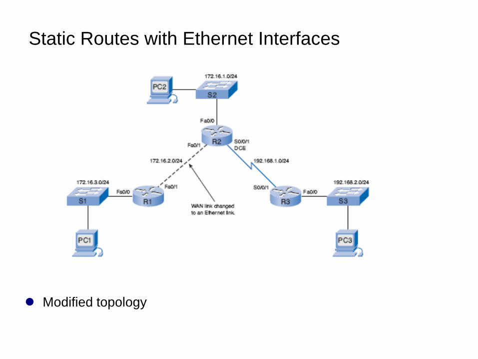
Static Routes with Ethernet Interfaces
Modified topology
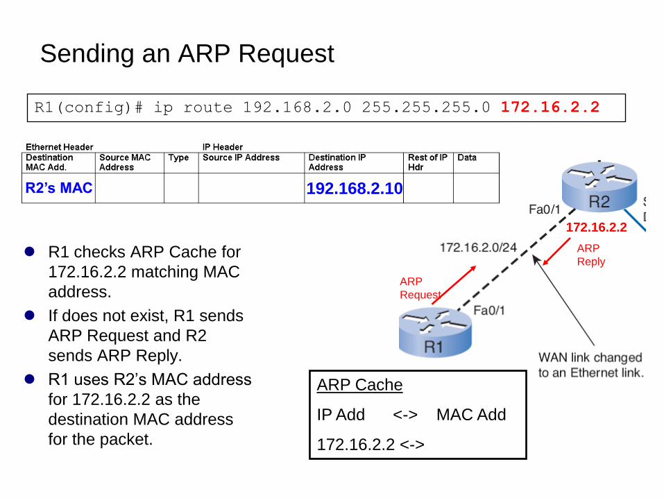
Sending an ARP Request
R1(config)# ip route 192.168.2.0 255.255.255.0 172.16.2.2
R1 checks ARP Cache for
172.16.2.2 matching MAC
address.
If does not exist, R1 sends
ARP Request and R2
sends ARP Reply.
R1 uses R2’s MAC address
for 172.16.2.2 as the
destination MAC address
for the packet.
ARP Cache
IP Add <-> MAC Add
172.16.2.2 <->
192.168.2.10R2’s MAC
172.16.2.2
ARP
Reply
ARP
Request
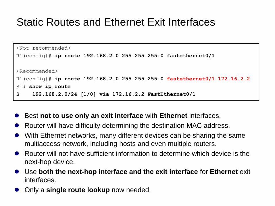
Static Routes and Ethernet Exit Interfaces
Best not to use only an exit interface with Ethernet interfaces.
Router will have difficulty determining the destination MAC address.
With Ethernet networks, many different devices can be sharing the same
multiaccess network, including hosts and even multiple routers.
Router will not have sufficient information to determine which device is the
next-hop device.
Use both the next-hop interface and the exit interface for Ethernet exit
interfaces.
Only a single route lookup now needed.
<Not recommended>
R1(config)# ip route 192.168.2.0 255.255.255.0 fastethernet0/1
<Recommended>
R1(config)# ip route 192.168.2.0 255.255.255.0 fastethernet0/1 172.16.2.2
R1# show ip route
S 192.168.2.0/24 [1/0] via 172.16.2.2 FastEthernet0/1
Advantages of Using an Exit Interface
with Static Routes
The is an advantage to using exit interfaces in static routes for both serial
point-to-point and Ethernet outbound networks is:
The routing table process only has to perform a single lookup to find the
exit interface instead of a second lookup to resolve a next-hop address.
Summary and
Default Static Routes
Summary Static Routes
Default Static Routes
Summarizing Routes
to reduce the size of the routing table
Summary route is a single route that can be used to represent multiple
routes.
Generally a set of contiguous networks (but do not have to be).
Have the same exit interface or next-hop IP address.
Example:
10.0.0.0/16, 10.1.0.0/16, 10.2.0.0/16, 10.3.0.0/16, 10.4.0.0/16,
10.5.0.0/16, all the way through 10.255.0.0/16
Can be represented by a single network address: 10.0.0.0/8.
Creates smaller routing tables
More efficient routing table lookup process more efficient.
A single static route can be used to represent dozens, hundreds, or even
thousands of routes.
As of March 2007, there are more than 200,000 routes in the Internet core
routers.
Most of these are summarized routes.
Summarizing Routes
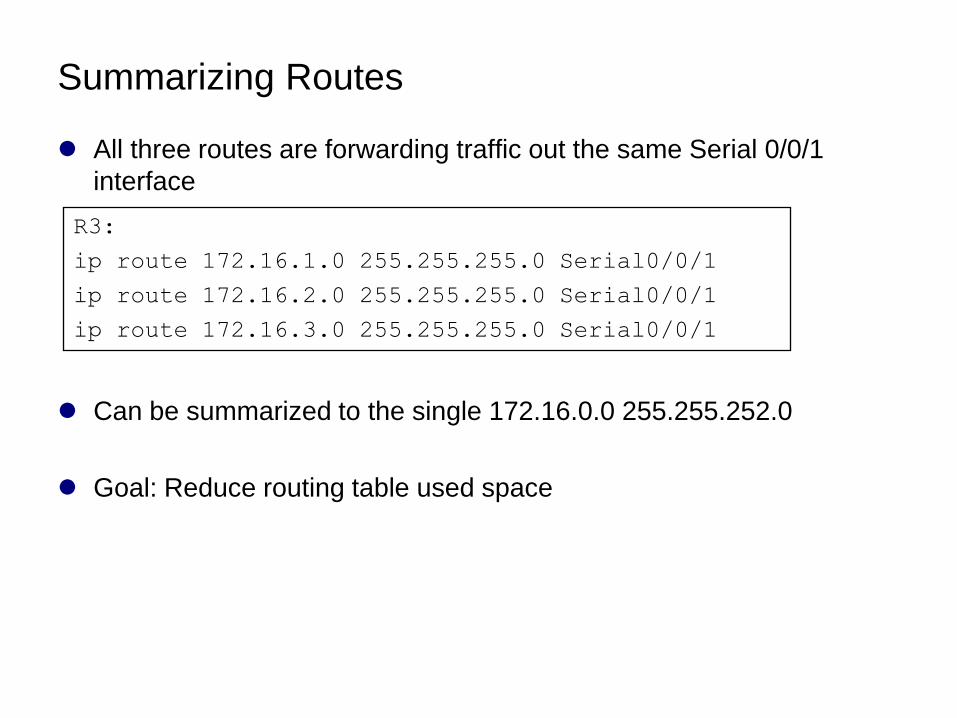
All three routes are forwarding traffic out the same Serial 0/0/1
interface
Can be summarized to the single 172.16.0.0 255.255.252.0
Goal: Reduce routing table used space
R3:
ip route 172.16.1.0 255.255.255.0 Serial0/0/1
ip route 172.16.2.0 255.255.255.0 Serial0/0/1
ip route 172.16.3.0 255.255.255.0 Serial0/0/1
Calculating a
Summary Route
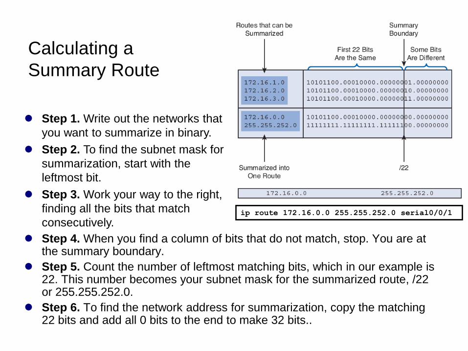
Step 4. When you find a column of bits that do not match, stop. You are at the summary boundary.
Step 5. Count the number of leftmost matching bits, which in our example is 22. This number becomes your subnet mask for the summarized route, /22 or 255.255.252.0.
Step 6. To find the network address for summarization, copy the matching 22 bits and add all 0 bits to the end to make 32 bits..
Step 1. Write out the networks that
you want to summarize in binary.
Step 2. To find the subnet mask for
summarization, start with the
leftmost bit.
Step 3. Work your way to the right,
finding all the bits that match
consecutively.ip route 172.16.0.0 255.255.252.0 serial0/0/1
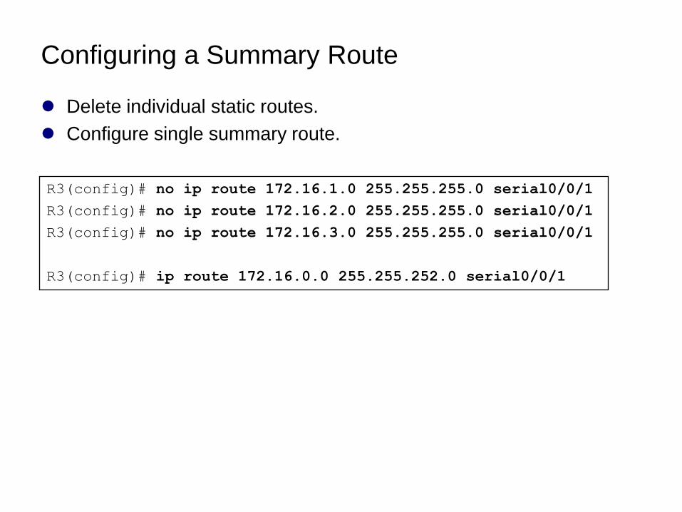
Configuring a Summary Route
Delete individual static routes.
Configure single summary route.
R3(config)# no ip route 172.16.1.0 255.255.255.0 serial0/0/1
R3(config)# no ip route 172.16.2.0 255.255.255.0 serial0/0/1
R3(config)# no ip route 172.16.3.0 255.255.255.0 serial0/0/1
R3(config)# ip route 172.16.0.0 255.255.252.0 serial0/0/1
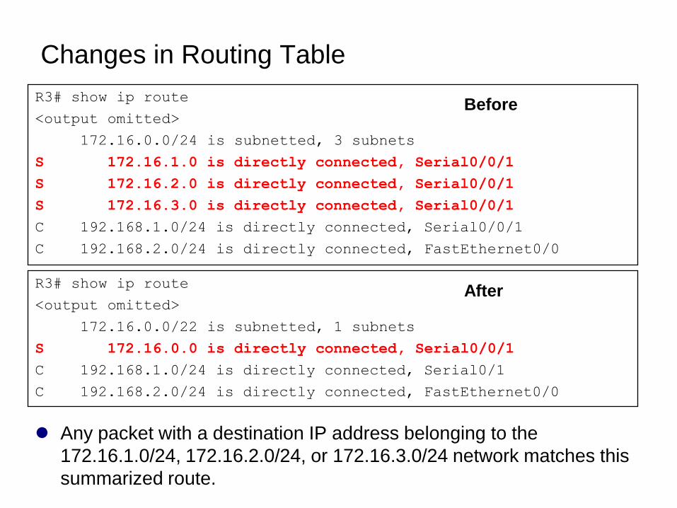
Changes in Routing Table
R3# show ip route
<output omitted>
172.16.0.0/24 is subnetted, 3 subnets
S 172.16.1.0 is directly connected, Serial0/0/1
S 172.16.2.0 is directly connected, Serial0/0/1
S 172.16.3.0 is directly connected, Serial0/0/1
C 192.168.1.0/24 is directly connected, Serial0/0/1
C 192.168.2.0/24 is directly connected, FastEthernet0/0
R3# show ip route
<output omitted>
172.16.0.0/22 is subnetted, 1 subnets
S 172.16.0.0 is directly connected, Serial0/0/1
C 192.168.1.0/24 is directly connected, Serial0/1
C 192.168.2.0/24 is directly connected, FastEthernet0/0
Any packet with a destination IP address belonging to the
172.16.1.0/24, 172.16.2.0/24, or 172.16.3.0/24 network matches this
summarized route.
Before
After
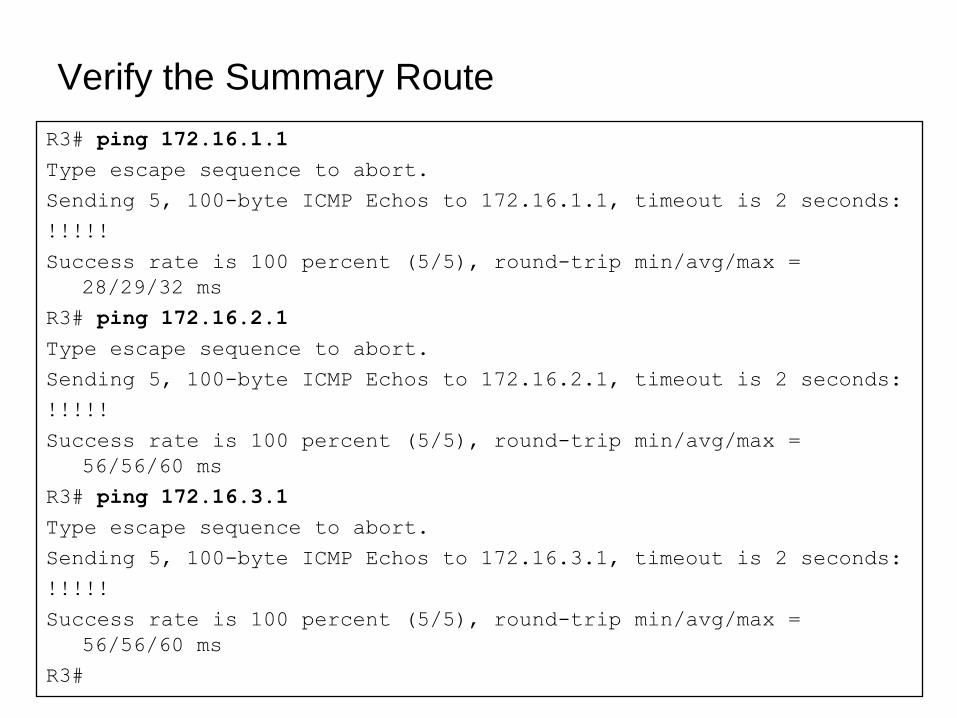
Verify the Summary Route
R3# ping 172.16.1.1
Type escape sequence to abort.
Sending 5, 100-byte ICMP Echos to 172.16.1.1, timeout is 2 seconds:
!!!!!
Success rate is 100 percent (5/5), round-trip min/avg/max =
28/29/32 ms
R3# ping 172.16.2.1
Type escape sequence to abort.
Sending 5, 100-byte ICMP Echos to 172.16.2.1, timeout is 2 seconds:
!!!!!
Success rate is 100 percent (5/5), round-trip min/avg/max =
56/56/60 ms
R3# ping 172.16.3.1
Type escape sequence to abort.
Sending 5, 100-byte ICMP Echos to 172.16.3.1, timeout is 2 seconds:
!!!!!
Success rate is 100 percent (5/5), round-trip min/avg/max =
56/56/60 ms
R3#
Default Static Route
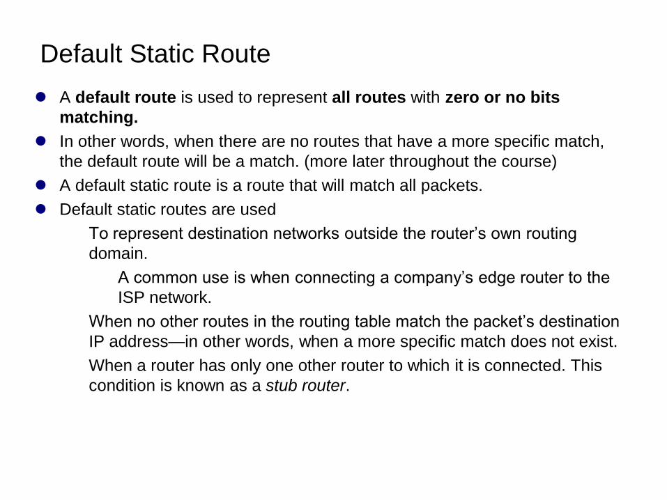
A default route is used to represent all routes with zero or no bits
matching.
In other words, when there are no routes that have a more specific match,
the default route will be a match. (more later throughout the course)
A default static route is a route that will match all packets.
Default static routes are used
To represent destination networks outside the router’s own routing
domain.
A common use is when connecting a company’s edge router to the
ISP network.
When no other routes in the routing table match the packet’s destination
IP address—in other words, when a more specific match does not exist.
When a router has only one other router to which it is connected. This
condition is known as a stub router.
Configuring a Default Static Route
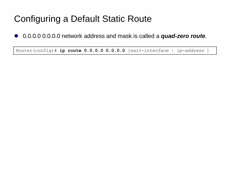
0.0.0.0 0.0.0.0 network address and mask is called a quad-zero route.
Router(config)# ip route 0.0.0.0 0.0.0.0 [exit-interface | ip-address ]
Configuring a Default Static Route
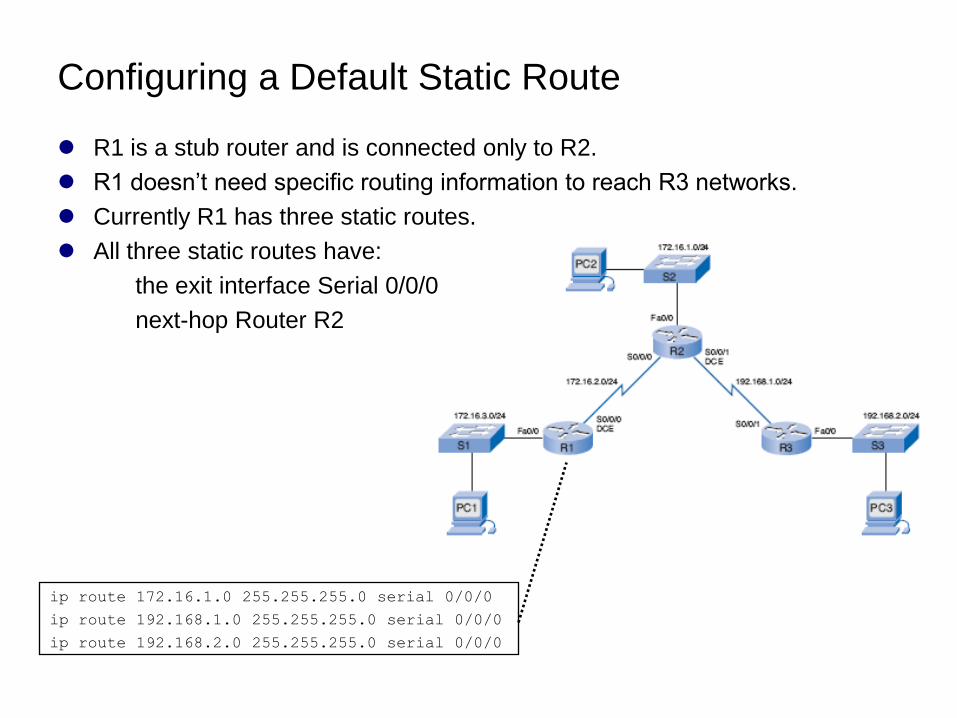
R1 is a stub router and is connected only to R2.
R1 doesn’t need specific routing information to reach R3 networks.
Currently R1 has three static routes.
All three static routes have:
the exit interface Serial 0/0/0
next-hop Router R2
ip route 172.16.1.0 255.255.255.0 serial 0/0/0
ip route 192.168.1.0 255.255.255.0 serial 0/0/0
ip route 192.168.2.0 255.255.255.0 serial 0/0/0
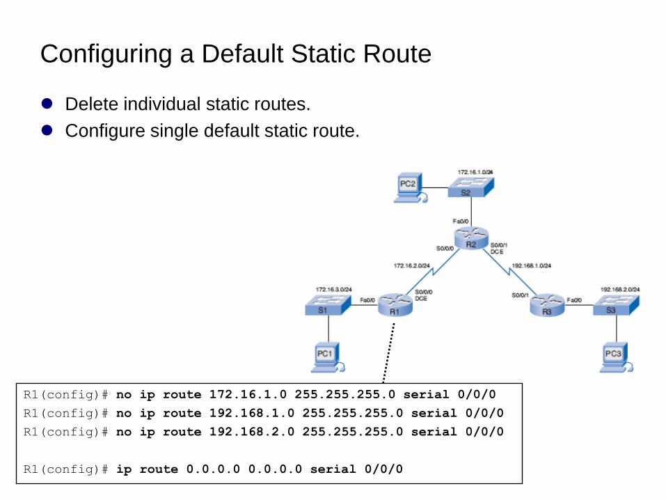
Configuring a Default Static Route
Delete individual static routes.
Configure single default static route.
R1(config)# no ip route 172.16.1.0 255.255.255.0 serial 0/0/0
R1(config)# no ip route 192.168.1.0 255.255.255.0 serial 0/0/0
R1(config)# no ip route 192.168.2.0 255.255.255.0 serial 0/0/0
R1(config)# ip route 0.0.0.0 0.0.0.0 serial 0/0/0
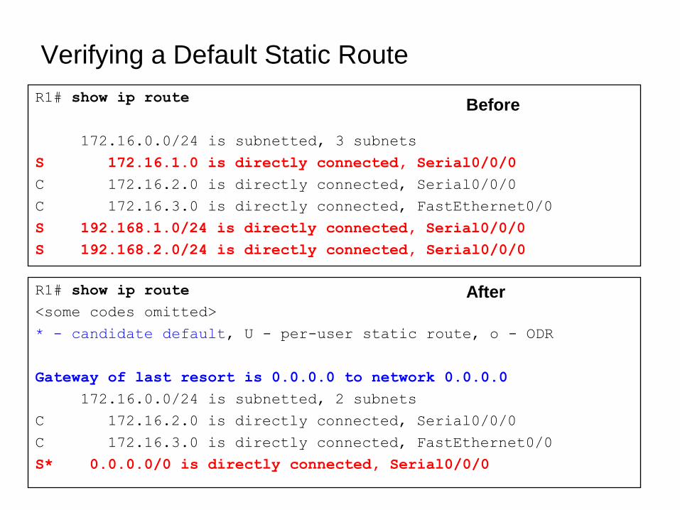
Verifying a Default Static Route
R1# show ip route
172.16.0.0/24 is subnetted, 3 subnets
S 172.16.1.0 is directly connected, Serial0/0/0
C 172.16.2.0 is directly connected, Serial0/0/0
C 172.16.3.0 is directly connected, FastEthernet0/0
S 192.168.1.0/24 is directly connected, Serial0/0/0
S 192.168.2.0/24 is directly connected, Serial0/0/0
R1# show ip route
<some codes omitted>
* - candidate default, U - per-user static route, o - ODR
Gateway of last resort is 0.0.0.0 to network 0.0.0.0
172.16.0.0/24 is subnetted, 2 subnets
C 172.16.2.0 is directly connected, Serial0/0/0
C 172.16.3.0 is directly connected, FastEthernet0/0
S* 0.0.0.0/0 is directly connected, Serial0/0/0
Before
After
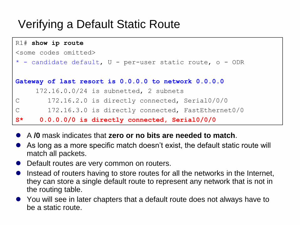
Verifying a Default Static Route
A /0 mask indicates that zero or no bits are needed to match.
As long as a more specific match doesn’t exist, the default static route will match all packets.
Default routes are very common on routers.
Instead of routers having to store routes for all the networks in the Internet, they can store a single default route to represent any network that is not in the routing table.
You will see in later chapters that a default route does not always have to be a static route.
R1# show ip route
<some codes omitted>
* - candidate default, U - per-user static route, o - ODR
Gateway of last resort is 0.0.0.0 to network 0.0.0.0
172.16.0.0/24 is subnetted, 2 subnets
C 172.16.2.0 is directly connected, Serial0/0/0
C 172.16.3.0 is directly connected, FastEthernet0/0
S* 0.0.0.0/0 is directly connected, Serial0/0/0
Managing and Troubleshooting
Static Routes
Static Routes and Packet Forwarding
Troubleshooting a Missing Route
Solving the Missing Route
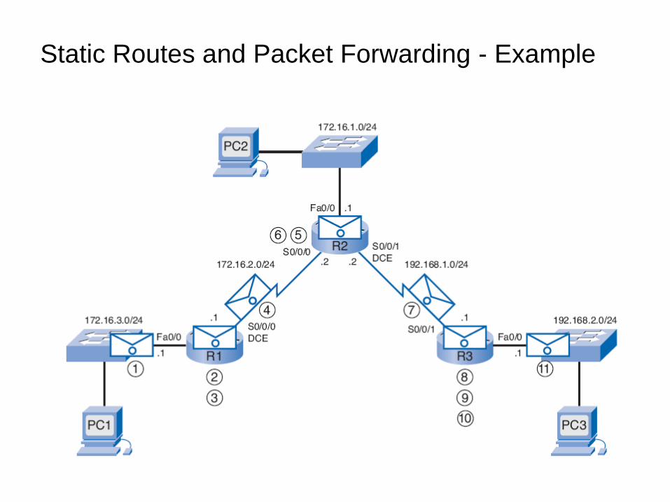
Static Routes and Packet Forwarding - Example
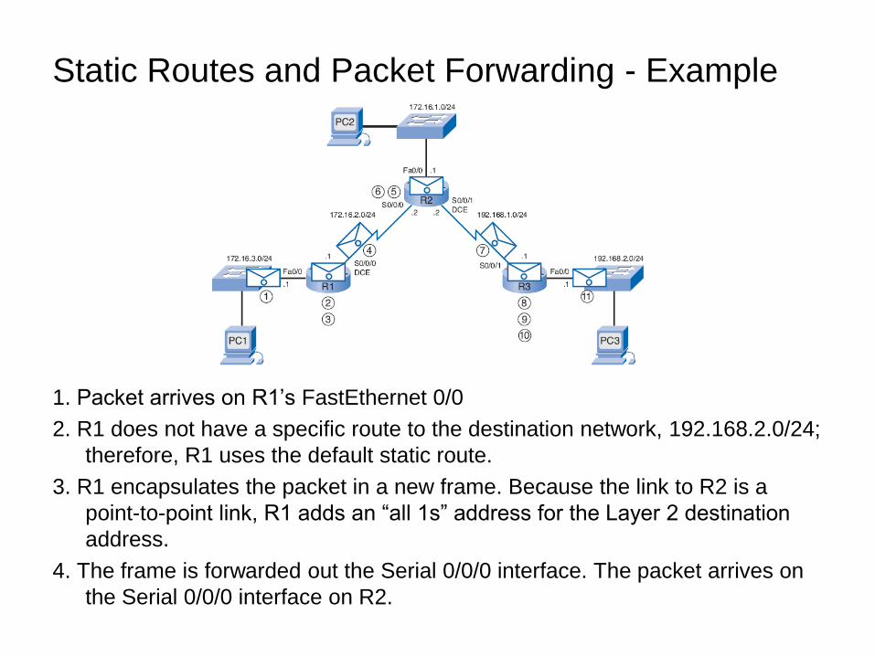
1. Packet arrives on R1’s FastEthernet 0/0
2. R1 does not have a specific route to the destination network, 192.168.2.0/24;
therefore, R1 uses the default static route.
3. R1 encapsulates the packet in a new frame. Because the link to R2 is a
point-to-point link, R1 adds an ―all 1s‖ address for the Layer 2 destination
address.
4. The frame is forwarded out the Serial 0/0/0 interface. The packet arrives on
the Serial 0/0/0 interface on R2.
Static Routes and Packet Forwarding - Example
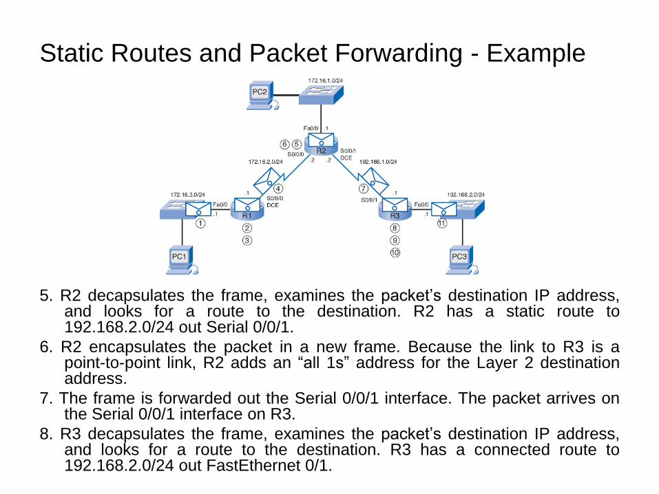
5. R2 decapsulates the frame, examines the packet’s destination IP address,and looks for a route to the destination. R2 has a static route to192.168.2.0/24 out Serial 0/0/1.
6. R2 encapsulates the packet in a new frame. Because the link to R3 is apoint-to-point link, R2 adds an ―all 1s‖ address for the Layer 2 destinationaddress.
7. The frame is forwarded out the Serial 0/0/1 interface. The packet arrives onthe Serial 0/0/1 interface on R3.
8. R3 decapsulates the frame, examines the packet’s destination IP address,and looks for a route to the destination. R3 has a connected route to192.168.2.0/24 out FastEthernet 0/1.
Static Routes and Packet Forwarding - Example
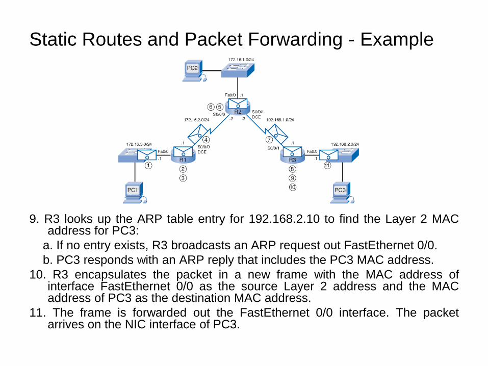
9. R3 looks up the ARP table entry for 192.168.2.10 to find the Layer 2 MACaddress for PC3:
a. If no entry exists, R3 broadcasts an ARP request out FastEthernet 0/0.
b. PC3 responds with an ARP reply that includes the PC3 MAC address.
10. R3 encapsulates the packet in a new frame with the MAC address ofinterface FastEthernet 0/0 as the source Layer 2 address and the MACaddress of PC3 as the destination MAC address.
11. The frame is forwarded out the FastEthernet 0/0 interface. The packetarrives on the NIC interface of PC3.
Static Routes and Packet Forwarding - Example
Troubleshooting a Missing Route
When end-to-end connectivity is a problem, begin by making sure
that you can ping your own interface and other devices on your own
directly connected networks.
When this has been verified, begin testing connectivity to remote
networks and from other devices.
Networks are subject to many different forces that can cause their
status to change quite often:
Interface failure
Dropped connection by a service provider
Oversaturation of links
Incorrect configuration entered by an administrator
Tools:
ping
traceroute
show ip route
show ip interface brief
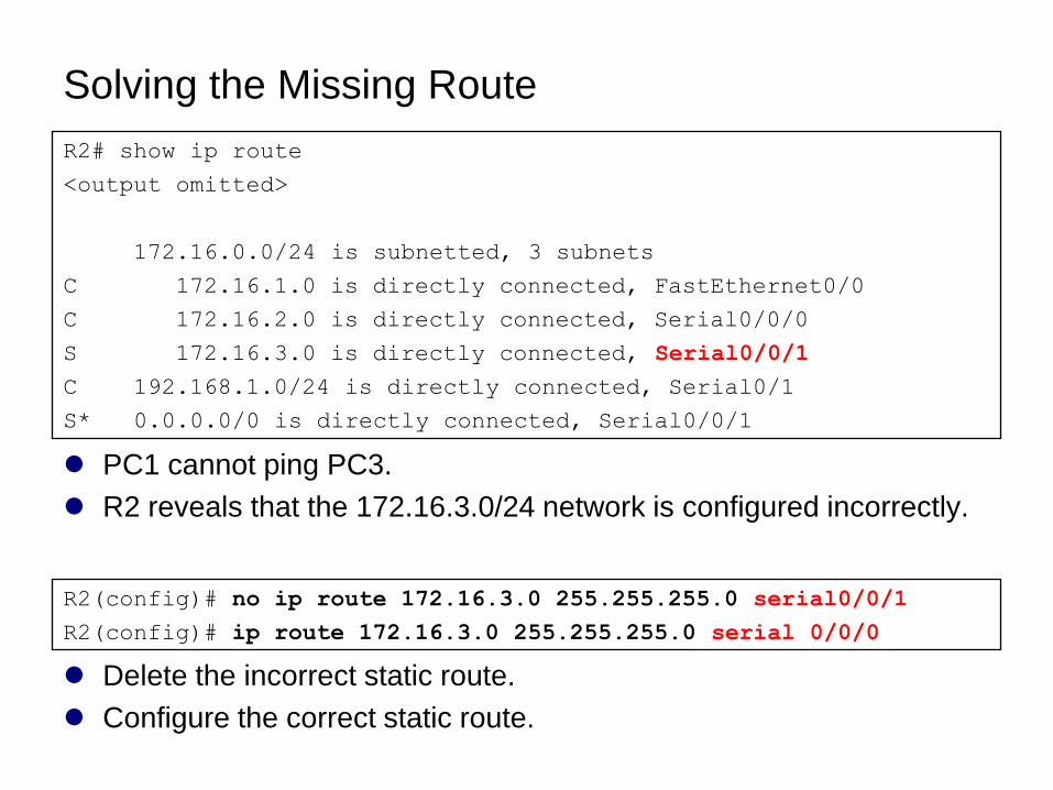
Solving the Missing Route
PC1 cannot ping PC3.
R2 reveals that the 172.16.3.0/24 network is configured incorrectly.
R2# show ip route
<output omitted>
172.16.0.0/24 is subnetted, 3 subnets
C 172.16.1.0 is directly connected, FastEthernet0/0
C 172.16.2.0 is directly connected, Serial0/0/0
S 172.16.3.0 is directly connected, Serial0/0/1
C 192.168.1.0/24 is directly connected, Serial0/1
S* 0.0.0.0/0 is directly connected, Serial0/0/1
Delete the incorrect static route.
Configure the correct static route.
R2(config)# no ip route 172.16.3.0 255.255.255.0 serial0/0/1
R2(config)# ip route 172.16.3.0 255.255.255.0 serial 0/0/0

This presentation is available at:
http://w3.ualg.pt/~jjose/cisco/
Original presentations from:
http://www.cabrillo.edu/~rgraziani/
Cisco curriculum available at:
http://cisco.netacad.net (Internet Explorer recommended)
After login, under: “Course Materials”