Chapter 2 Part A: In-car engine repair procedures motoru m40.pdf · 1 General information This Part...
20
2A General Displacement 3-series, E30 body style 316i (1988 to 1991) . . . . . . . . . . . . . . . . . . . . . . . . . . . . . . . . . . . 1596 cc (M40/4-cylinder engine) 316 (1983 to 1988) and 318i (1983 to 1987) . . . . . . . . . . . . . . . . 1766 cc (M10/4-cylinder engine) 318i (1987 1991) . . . . . . . . . . . . . . . . . . . . . . . . . . . . . . . . . . . . . 1796 cc (M40/4-cylinder engine) 320i (1987 to 1991) . . . . . . . . . . . . . . . . . . . . . . . . . . . . . . . . . . . 1990 cc (M20/6-cylinder engine) 325i (1987 to 1991) . . . . . . . . . . . . . . . . . . . . . . . . . . . . . . . . . . . 2494 cc (M20/6-cylinder engine) 5-series, E28 body style (“old-shape”) 518 (1981 to 1985) and 518i (1985 to 1988) . . . . . . . . . . . . . . . . 1766 cc (M10/4-cylinder engine) 525i (1981 to 1988) . . . . . . . . . . . . . . . . . . . . . . . . . . . . . . . . . . . 2494 cc (M30/6-cylinder engine) 528i (1981 to 1988) . . . . . . . . . . . . . . . . . . . . . . . . . . . . . . . . . . . 2788 cc (M30/6-cylinder engine) 535i (1985 to 1988) . . . . . . . . . . . . . . . . . . . . . . . . . . . . . . . . . . . 3430 cc (M30/6-cylinder engine) M535i (1985 to 1988) . . . . . . . . . . . . . . . . . . . . . . . . . . . . . . . . . 3430 cc (M30/6-cylinder engine) 5-series, E34 body style (“new-shape”) 518i (1990 to 1993) . . . . . . . . . . . . . . . . . . . . . . . . . . . . . . . . . . . 1796 cc (M40/4-cylinder engine) 520i (1988 to 1991) . . . . . . . . . . . . . . . . . . . . . . . . . . . . . . . . . . . 1990 cc (M20/6-cylinder engine) 525i (1988 to 1991) . . . . . . . . . . . . . . . . . . . . . . . . . . . . . . . . . . . 2494 cc (M20/6-cylinder engine) 530i (1988 to 1991) . . . . . . . . . . . . . . . . . . . . . . . . . . . . . . . . . . . 2986 cc (M30/6-cylinder engine) 535i (1988 to 1993) . . . . . . . . . . . . . . . . . . . . . . . . . . . . . . . . . . . 3430 cc (M30/6-cylinder engine) Firing order Four-cylinder engine . . . . . . . . . . . . . . . . . . . . . . . . . . . . . . . . . . . . . . 1-3-4-2 Six-cylinder engine . . . . . . . . . . . . . . . . . . . . . . . . . . . . . . . . . . . . . . . 1-5-3-6-2-4 Lubrication system Oil pressure (all engines) At idle . . . . . . . . . . . . . . . . . . . . . . . . . . . . . . . . . . . . . . . . . . . . . . . . . 0.5 to 2.0 bars Running (for example, at 4000 rpm) . . . . . . . . . . . . . . . . . . . . . . . . . . 4 bars or above (typically) Oil pump rotor clearance - M40 engine (body-to-outer rotor/outer rotor-to-inner rotor) . . . . . . . . . . . . . . . . . . . 0.12 mm to 0.20 mm Oil pump pressure relief valve spring length - M40 engine . . . . . . . . . . 84.1 mm Chapter 2 Part A: In-car engine repair procedures Camshaft - removal, inspection and refitting . . . . . . See Chapter 2B Compression check . . . . . . . . . . . . . . . . . . . . . . . . . See Chapter 2B Crankshaft rear oil seal - renewal . . . . . . . . . . . . . . . . . . . . . . . . . . . 16 Cylinder head - removal and refitting . . . . . . . . . . . . . . . . . . . . . . . . 12 Cylinder head - dismantling and inspection . . . . . . . See Chapter 2B Drivebelt check, adjustment and renewal . . . . . . . . See Chapter 1 Engine - removal and refitting . . . . . . . . . . . . . . . . . See Chapter 2B Engine mountings - check and renewal . . . . . . . . . . . . . . . . . . . . . . 17 Engine oil and filter change . . . . . . . . . . . . . . . . . . . See Chapter 1 Engine overhaul - general information . . . . . . . . . . . See Chapter 2B Exhaust manifold - removal and refitting . . . . . . . . . . . . . . . . . . . . . 6 Flywheel/driveplate - removal and refitting . . . . . . . . . . . . . . . . . . . 15 Front oil seals - renewal . . . . . . . . . . . . . . . . . . . . . . . . . . . . . . . . . . 11 General information . . . . . . . . . . . . . . . . . . . . . . . . . . . . . . . . . . . . . 1 Intake manifold - removal and refitting . . . . . . . . . . . . . . . . . . . . . . . 5 Oil pump - removal, inspection and refitting . . . . . . . . . . . . . . . . . . 14 Repair operations possible with the engine in the vehicle . . . . . . . . 2 Rocker arm and shaft assembly - dismantling, inspection and reassembly . . . . . . . . . . . . . . . . . . . . . . . . . . . See Chapter 2B Spark plug renewal . . . . . . . . . . . . . . . . . . . . . . . . . . See Chapter 1 Sump - removal and refitting . . . . . . . . . . . . . . . . . . . . . . . . . . . . . . 13 Timing belt and sprockets - removal, inspection and refitting . . . . . 10 Timing belt covers - removal and refitting . . . . . . . . . . . . . . . . . . . . . 9 Timing chain and sprockets - removal, inspection and refitting . . . . 8 Timing chain covers - removal and refitting . . . . . . . . . . . . . . . . . . . 7 Top Dead Centre (TDC) for No 1 piston - locating . . . . . . . . . . . . . . 3 Valve clearance check and adjustment . . . . . . . . . . . See Chapter 1 Valve cover - removal and refitting . . . . . . . . . . . . . . . . . . . . . . . . . . 4 Valves - servicing . . . . . . . . . . . . . . . . . . . . . . . . . . . See Chapter 2B 2A•1 Easy, suitable for novice with little experience Fairly easy, suitable for beginner with some experience Fairly difficult, suitable for competent DIY mechanic Difficult, suitable for experienced DIY mechanic Very difficult, suitable for expert DIY or professional Degrees of difficulty Specifications Contents
Transcript of Chapter 2 Part A: In-car engine repair procedures motoru m40.pdf · 1 General information This Part...

2A
GeneralDisplacement
3-series, E30 body style316i (1988 to 1991) . . . . . . . . . . . . . . . . . . . . . . . . . . . . . . . . . . . 1596 cc (M40/4-cylinder engine)316 (1983 to 1988) and 318i (1983 to 1987) . . . . . . . . . . . . . . . . 1766 cc (M10/4-cylinder engine)318i (1987 1991) . . . . . . . . . . . . . . . . . . . . . . . . . . . . . . . . . . . . . 1796 cc (M40/4-cylinder engine)320i (1987 to 1991) . . . . . . . . . . . . . . . . . . . . . . . . . . . . . . . . . . . 1990 cc (M20/6-cylinder engine)325i (1987 to 1991) . . . . . . . . . . . . . . . . . . . . . . . . . . . . . . . . . . . 2494 cc (M20/6-cylinder engine)
5-series, E28 body style (“old-shape”)518 (1981 to 1985) and 518i (1985 to 1988) . . . . . . . . . . . . . . . . 1766 cc (M10/4-cylinder engine)525i (1981 to 1988) . . . . . . . . . . . . . . . . . . . . . . . . . . . . . . . . . . . 2494 cc (M30/6-cylinder engine)528i (1981 to 1988) . . . . . . . . . . . . . . . . . . . . . . . . . . . . . . . . . . . 2788 cc (M30/6-cylinder engine)535i (1985 to 1988) . . . . . . . . . . . . . . . . . . . . . . . . . . . . . . . . . . . 3430 cc (M30/6-cylinder engine)M535i (1985 to 1988) . . . . . . . . . . . . . . . . . . . . . . . . . . . . . . . . . 3430 cc (M30/6-cylinder engine)
5-series, E34 body style (“new-shape”)518i (1990 to 1993) . . . . . . . . . . . . . . . . . . . . . . . . . . . . . . . . . . . 1796 cc (M40/4-cylinder engine)520i (1988 to 1991) . . . . . . . . . . . . . . . . . . . . . . . . . . . . . . . . . . . 1990 cc (M20/6-cylinder engine)525i (1988 to 1991) . . . . . . . . . . . . . . . . . . . . . . . . . . . . . . . . . . . 2494 cc (M20/6-cylinder engine)530i (1988 to 1991) . . . . . . . . . . . . . . . . . . . . . . . . . . . . . . . . . . . 2986 cc (M30/6-cylinder engine)535i (1988 to 1993) . . . . . . . . . . . . . . . . . . . . . . . . . . . . . . . . . . . 3430 cc (M30/6-cylinder engine)
Firing orderFour-cylinder engine . . . . . . . . . . . . . . . . . . . . . . . . . . . . . . . . . . . . . . 1-3-4-2Six-cylinder engine . . . . . . . . . . . . . . . . . . . . . . . . . . . . . . . . . . . . . . . 1-5-3-6-2-4
Lubrication systemOil pressure (all engines)
At idle . . . . . . . . . . . . . . . . . . . . . . . . . . . . . . . . . . . . . . . . . . . . . . . . . 0.5 to 2.0 barsRunning (for example, at 4000 rpm) . . . . . . . . . . . . . . . . . . . . . . . . . . 4 bars or above (typically)
Oil pump rotor clearance - M40 engine(body-to-outer rotor/outer rotor-to-inner rotor) . . . . . . . . . . . . . . . . . . . 0.12 mm to 0.20 mmOil pump pressure relief valve spring length - M40 engine . . . . . . . . . . 84.1 mm
Chapter 2 Part A:In-car engine repair procedures
Camshaft - removal, inspection and refitting . . . . . . See Chapter 2BCompression check . . . . . . . . . . . . . . . . . . . . . . . . . See Chapter 2BCrankshaft rear oil seal - renewal . . . . . . . . . . . . . . . . . . . . . . . . . . . 16Cylinder head - removal and refitting . . . . . . . . . . . . . . . . . . . . . . . . 12Cylinder head - dismantling and inspection . . . . . . . See Chapter 2BDrivebelt check, adjustment and renewal . . . . . . . . See Chapter 1Engine - removal and refitting . . . . . . . . . . . . . . . . . See Chapter 2BEngine mountings - check and renewal . . . . . . . . . . . . . . . . . . . . . . 17Engine oil and filter change . . . . . . . . . . . . . . . . . . . See Chapter 1Engine overhaul - general information . . . . . . . . . . . See Chapter 2BExhaust manifold - removal and refitting . . . . . . . . . . . . . . . . . . . . . 6Flywheel/driveplate - removal and refitting . . . . . . . . . . . . . . . . . . . 15Front oil seals - renewal . . . . . . . . . . . . . . . . . . . . . . . . . . . . . . . . . . 11General information . . . . . . . . . . . . . . . . . . . . . . . . . . . . . . . . . . . . . 1Intake manifold - removal and refitting . . . . . . . . . . . . . . . . . . . . . . . 5
Oil pump - removal, inspection and refitting . . . . . . . . . . . . . . . . . . 14Repair operations possible with the engine in the vehicle . . . . . . . . 2Rocker arm and shaft assembly - dismantling, inspection
and reassembly . . . . . . . . . . . . . . . . . . . . . . . . . . . See Chapter 2BSpark plug renewal . . . . . . . . . . . . . . . . . . . . . . . . . . See Chapter 1Sump - removal and refitting . . . . . . . . . . . . . . . . . . . . . . . . . . . . . . 13Timing belt and sprockets - removal, inspection and refitting . . . . . 10Timing belt covers - removal and refitting . . . . . . . . . . . . . . . . . . . . . 9Timing chain and sprockets - removal, inspection and refitting . . . . 8Timing chain covers - removal and refitting . . . . . . . . . . . . . . . . . . . 7Top Dead Centre (TDC) for No 1 piston - locating . . . . . . . . . . . . . . 3Valve clearance check and adjustment . . . . . . . . . . . See Chapter 1Valve cover - removal and refitting . . . . . . . . . . . . . . . . . . . . . . . . . . 4Valves - servicing . . . . . . . . . . . . . . . . . . . . . . . . . . . See Chapter 2B
2A•1
Easy, suitable fornovice with littleexperience
Fairly easy, suitablefor beginner withsome experience
Fairly difficult,suitable for competentDIY mechanic
Difficult, suitable forexperienced DIYmechanic
Very difficult,suitable for expertDIY or professional
Degrees of difficulty
Specifications
Contents
Torque wrench settings NmTiming chain tensioner plug . . . . . . . . . . . . . . . . . . . . . . . . . . . . . . . . . . 35Timing belt tensioner bolts . . . . . . . . . . . . . . . . . . . . . . . . . . . . . . . . . . . 22Camshaft sprocket-to-camshaft bolt
M10 and M30 engines . . . . . . . . . . . . . . . . . . . . . . . . . . . . . . . . . . . . 10M20 and M40 engines . . . . . . . . . . . . . . . . . . . . . . . . . . . . . . . . . . . . 65Flange to camshaft (M30 engine) . . . . . . . . . . . . . . . . . . . . . . . . . . . . 145
Timing chain or belt covers-to-engineM6 bolts . . . . . . . . . . . . . . . . . . . . . . . . . . . . . . . . . . . . . . . . . . . . . . . 10M8 bolts . . . . . . . . . . . . . . . . . . . . . . . . . . . . . . . . . . . . . . . . . . . . . . . 22M10 (bolt size) bolts . . . . . . . . . . . . . . . . . . . . . . . . . . . . . . . . . . . . . . 47
Crankshaft pulley bolts . . . . . . . . . . . . . . . . . . . . . . . . . . . . . . . . . . . . . . 22Crankshaft hub bolt or nut
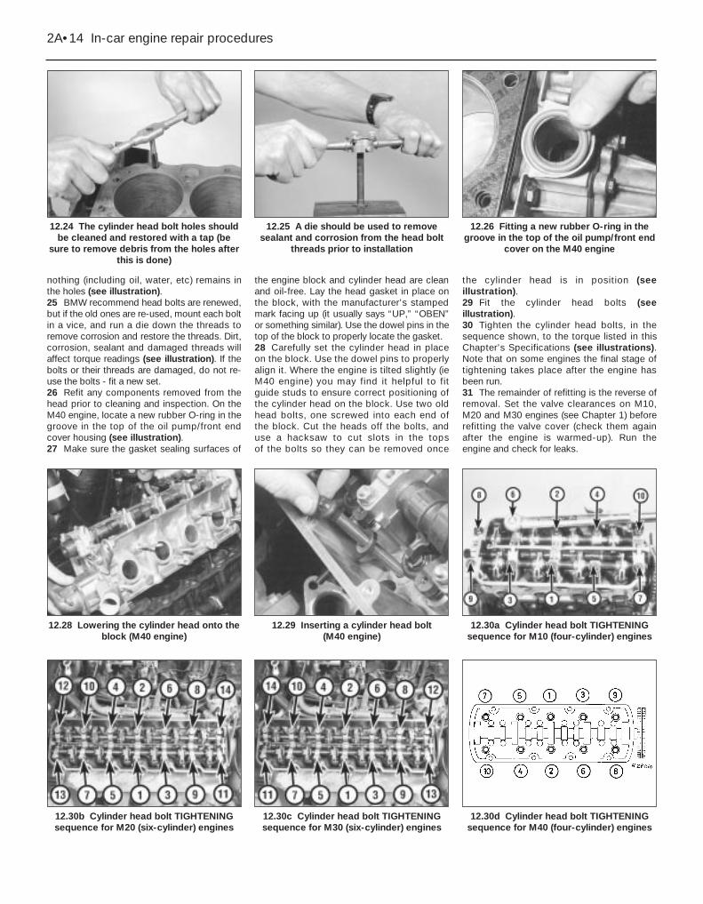
M10 engine . . . . . . . . . . . . . . . . . . . . . . . . . . . . . . . . . . . . . . . . . . . . . 190M20 engine . . . . . . . . . . . . . . . . . . . . . . . . . . . . . . . . . . . . . . . . . . . . . 410M30 engine . . . . . . . . . . . . . . . . . . . . . . . . . . . . . . . . . . . . . . . . . . . . . 440M40 engine . . . . . . . . . . . . . . . . . . . . . . . . . . . . . . . . . . . . . . . . . . . . . 310
Cylinder head bolts*M10 four-cylinder engine
Stage 1 . . . . . . . . . . . . . . . . . . . . . . . . . . . . . . . . . . . . . . . . . . . . . . 60Stage 2 (wait 15 minutes) . . . . . . . . . . . . . . . . . . . . . . . . . . . . . . . . Angle-tighten an additional 33°Stage 3 (engine at normal operating temperature) . . . . . . . . . . . . . Angle-tighten an additional 25°
M20 six-cylinder engine with hex-head boltsStage 1 . . . . . . . . . . . . . . . . . . . . . . . . . . . . . . . . . . . . . . . . . . . . . . 40Stage 2 (wait 15 minutes) . . . . . . . . . . . . . . . . . . . . . . . . . . . . . . . . 60Stage 3 (engine at normal operating temperature) . . . . . . . . . . . . . Angle-tighten an additional 25°
M20 six-cylinder engine with Torx-head boltsStage 1 . . . . . . . . . . . . . . . . . . . . . . . . . . . . . . . . . . . . . . . . . . . . . . 30Stage 2 . . . . . . . . . . . . . . . . . . . . . . . . . . . . . . . . . . . . . . . . . . . . . . Angle-tighten an additional 90°Stage 3 . . . . . . . . . . . . . . . . . . . . . . . . . . . . . . . . . . . . . . . . . . . . . . Angle-tighten an additional 90°
M30 six-cylinder engine (up to and including 1987 model year)Stage 1 . . . . . . . . . . . . . . . . . . . . . . . . . . . . . . . . . . . . . . . . . . . . . . 60Stage 2 (wait 15 minutes) . . . . . . . . . . . . . . . . . . . . . . . . . . . . . . . . Angle-tighten an additional 33°Stage 3 (engine at normal operating temperature) . . . . . . . . . . . . . Angle-tighten an additional 33°
M30 six-cylinder engine (from 1988 model year)Stage 1 . . . . . . . . . . . . . . . . . . . . . . . . . . . . . . . . . . . . . . . . . . . . . . 60Stage 2 (wait 20 minutes) . . . . . . . . . . . . . . . . . . . . . . . . . . . . . . . . 80Stage 3 (engine at normal operating temperature) . . . . . . . . . . . . . Angle-tighten an additional 35°
M40 four-cylinder engineStage 1 . . . . . . . . . . . . . . . . . . . . . . . . . . . . . . . . . . . . . . . . . . . . . . 30Stage 2 . . . . . . . . . . . . . . . . . . . . . . . . . . . . . . . . . . . . . . . . . . . . . . Angle-tighten an additional 90°Stage 3 . . . . . . . . . . . . . . . . . . . . . . . . . . . . . . . . . . . . . . . . . . . . . . Angle-tighten an additional 90°
Intake manifold-to-cylinder head boltsM8 bolt . . . . . . . . . . . . . . . . . . . . . . . . . . . . . . . . . . . . . . . . . . . . . . . . 22M7 bolt . . . . . . . . . . . . . . . . . . . . . . . . . . . . . . . . . . . . . . . . . . . . . . . . 15M6 bolt . . . . . . . . . . . . . . . . . . . . . . . . . . . . . . . . . . . . . . . . . . . . . . . . 10
Exhaust manifold-to-cylinder head nutsM6 nut . . . . . . . . . . . . . . . . . . . . . . . . . . . . . . . . . . . . . . . . . . . . . . . . . 10M7 nut . . . . . . . . . . . . . . . . . . . . . . . . . . . . . . . . . . . . . . . . . . . . . . . . . 15
Flywheel/driveplate boltsManual transmission . . . . . . . . . . . . . . . . . . . . . . . . . . . . . . . . . . . . . . 105Automatic transmission . . . . . . . . . . . . . . . . . . . . . . . . . . . . . . . . . . . 120
Intermediate shaft sprocket bolt (M20 engines) . . . . . . . . . . . . . . . . . . . 60Sump-to-block bolts . . . . . . . . . . . . . . . . . . . . . . . . . . . . . . . . . . . . . . . . 9 to 11Oil pump bolts (except M40 engines) . . . . . . . . . . . . . . . . . . . . . . . . . . . 22Oil pump sprocket bolts (M10 and M30 engines) . . . . . . . . . . . . . . . . . 10Oil pump cover plate-to-engine front end cover (M40 engines) . . . . . . . 9Front end cover-to-engine bolts (M20 and M40 engines)
M6 bolts . . . . . . . . . . . . . . . . . . . . . . . . . . . . . . . . . . . . . . . . . . . . . . . 10M8 bolts . . . . . . . . . . . . . . . . . . . . . . . . . . . . . . . . . . . . . . . . . . . . . . . 22
Crankshaft rear oil seal retainer-to-block boltsM6 bolts . . . . . . . . . . . . . . . . . . . . . . . . . . . . . . . . . . . . . . . . . . . . . . . 9M8 bolts . . . . . . . . . . . . . . . . . . . . . . . . . . . . . . . . . . . . . . . . . . . . . . . 22
* BMW recommend that the cylinder head bolts are renewed as a matter of course.
2A•2 In-car engine repair procedures
1 General information
This Part of Chapter 2 is devoted to in-vehicle engine repair procedures. Allinformation concerning engine removal andrefitting and engine block and cylinder headoverhaul can be found in Chapter 2B.
The following repair procedures are basedon the assumption that the engine is still fittedin the vehicle. If the engine has been removedfrom the vehicle and mounted on a stand,many of the steps outlined in this Part ofChapter 2 will not apply.
The Specifications included in this Part ofChapter 2 apply only to the procedurescontained in this Part. Chapter 2B containsthe Specifications necessary for cylinder headand engine block rebuilding.
The single overhead camshaft four- andsix-cylinder engines covered in this manualare very similar in design. Where there aredifferences, they will be pointed out.
The means by which the overheadcamshaft is driven varies according to enginetype; M10 and M30 engines use a timingchain, while M20 and M40 engines have atiming belt.
2 Repair operations possiblewith the engine in the vehicle
Many major repair operations can beaccomplished without removing the enginefrom the vehicle.
Clean the engine compartment and theexterior of the engine with some type ofdegreaser before any work is done. It willmake the job easier, and help keep dirt out ofthe internal areas of the engine.
Depending on the components involved, itmay be helpful to remove the bonnet toimprove access to the engine as repairs areperformed (see Chapter 11 if necessary).Cover the wings to prevent damage to thepaint. Special pads are available, but an oldbedspread or blanket will also work.
If vacuum, exhaust, oil or coolant leaksdevelop, indicating a need for gasket or sealrenewal, the repairs can generally be madewith the engine in the vehicle. The intake andexhaust manifold gaskets, sump gasket,crankshaft oil seals and cylinder head gasketare all accessible with the engine in place.
Exterior components, such as the intakeand exhaust manifolds, the sump, the oilpump, the water pump, the starter motor, thealternator, the distributor and the fuel systemcomponents, can be removed for repair withthe engine in place.
The cylinder head can be removed withoutremoving the engine, so this procedure iscovered in this Part of Chapter 2. Camshaft,rocker arm and valve component servicing is
most easily accomplished with the cylinderhead removed; these procedures are coveredin Part B of this Chapter. Note, however, thatthe camshaft on the M40 engine may beremoved with the engine in the vehicle since itis retained by bearing caps.
In extreme cases caused by a lack ofnecessary equipment, repair or renewal ofpiston rings, pistons, connecting rods andbig-end bearings is possible with the engine inthe vehicle. However, this practice is notrecommended, because of the cleaning andpreparation work that must be done to thecomponents involved.
3 Top Dead Centre (TDC) forNo 1 piston - locating 2
Note 1: The following procedure is based onthe assumption that the distributor (ifapplicable) is correctly fitted. If you are tryingto locate TDC to refit the distributor correctly,piston position must be determined by feelingfor compression at the No 1 spark plug hole,then aligning the ignition timing marks orinserting the timing tool in the flywheel, asapplicable.Note 2: The No 1 cylinder is the one closest tothe radiator.1 Top Dead Centre (TDC) is the highest pointin the cylinder that each piston reaches as ittravels up and down when the crankshaftturns. Each piston reaches TDC on thecompression stroke and again on the exhauststroke, but TDC generally refers to pistonposition on the compression stroke.2 Positioning the piston at TDC is an essentialpart of many procedures, such as timing beltor chain removal and distributor removal. 3 Before beginning this procedure, be sure toplace the transmission in Neutral, and applythe handbrake or chock the rear wheels. Also,disable the ignition system by detaching thecoil wire from the centre terminal of thedistributor cap, and earthing it on the engineblock with a jumper wire. Remove the sparkplugs (see Chapter 1).4 In order to bring any piston to TDC, thecrankshaft must be turned using one of themethods outlined below. When looking at thefront of the engine, normal crankshaft rotationis clockwise.(a) The preferred method is to turn the
crankshaft with a socket and ratchetattached to the bolt threaded into thefront of the crankshaft.
(b) A remote starter switch, which may savesome time, can also be used. Follow theinstructions included with the switch.Once the piston is close to TDC, use asocket and ratchet as described in theprevious paragraph.
(c) If an assistant is available to turn theignition switch to the Start position inshort bursts, you can get the piston closeto TDC without a remote starter switch.
Make sure your assistant is out of thevehicle, away from the ignition switch,then use a socket and ratchet asdescribed in (a) to complete theprocedure.
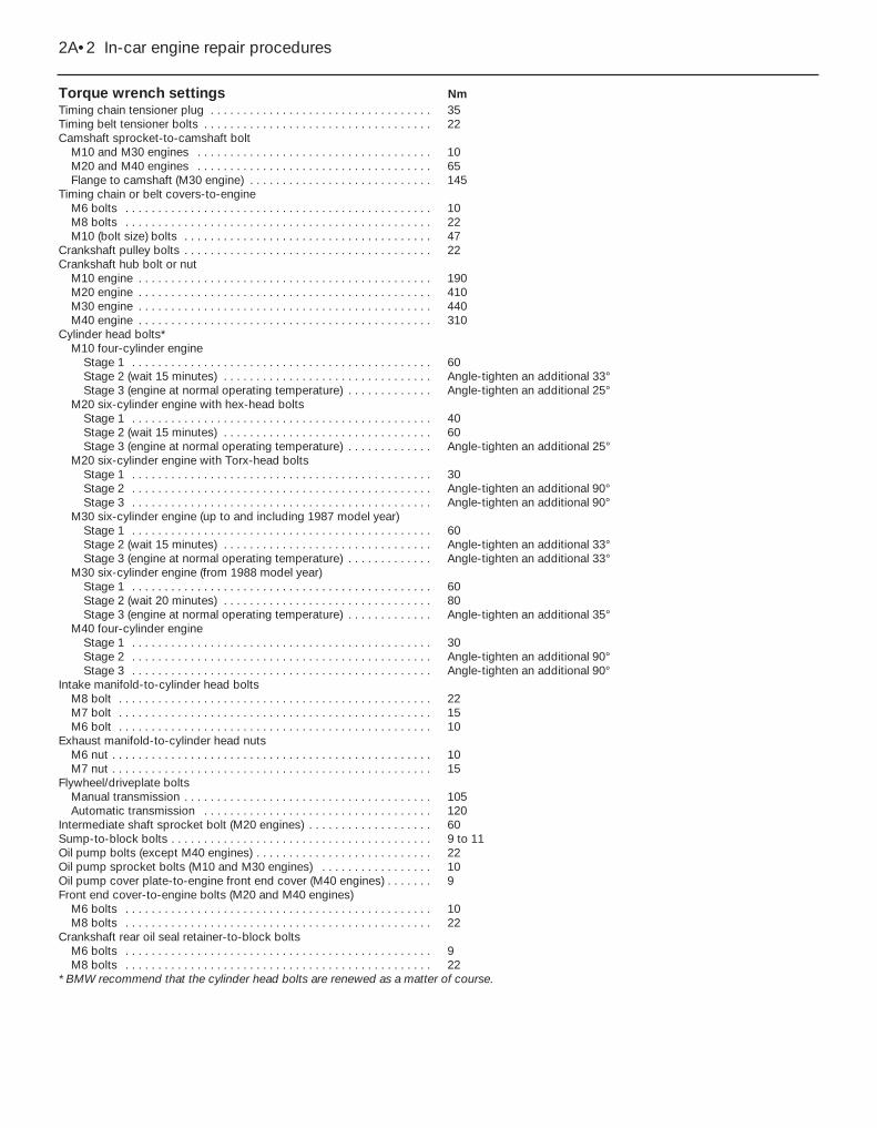
5 Note the position of the terminal for the No 1 spark plug lead on the distributor cap. Ifthe terminal isn’t marked, follow the plug leadfrom the No 1 cylinder spark plug to the cap(No 1 cylinder is nearest the radiator).6 Use a felt-tip pen or chalk to make a markdirectly below the No 1 terminal on thedistributor body or timing cover.7 Detach the distributor cap, and set it aside(see Chapter 1 if necessary).8 Turn the crankshaft (see paragraph 4above) until the timing marks (located at thefront of the engine) are aligned (seeillustration). The M40 engine does not haveany timing marks at the front of the engine,but instead has a timing hole in the flywheelwhich must be aligned with a hole in the rearflange of the cylinder block. On this engine,turn the crankshaft until the distributor rotor isapproaching the No 1 TDC position, thencontinue to turn the crankshaft until a suitableclose-fitting drill can be inserted through thehole in the cylinder block and into theflywheel.9 Look at the distributor rotor - it should bepointing directly at the mark you made on thedistributor body or timing cover.10 If the rotor is 180 degrees out, the No 1piston is at TDC on the exhaust stroke.11 To get the piston to TDC on thecompression stroke, turn the crankshaft onecomplete turn (360°) clockwise. The rotorshould now be pointing at the mark on thedistributor or timing cover. When the rotor ispointing at the No 1 spark plug lead terminalin the distributor cap and the ignition timingmarks are aligned, the No 1 piston is at TDCon the compression stroke. Note: If it’simpossible to align the ignition timing markswhen the rotor is pointing at the mark, thetiming belt or chain may have jumped theteeth on the sprockets, or may have beenfitted incorrectly.
In-car engine repair procedures 2A•3
3.8 Align the notch in the pulley with thenotch on the timing plate, then check to
see if the distributor rotor is pointing to theNo 1 cylinder (if not, the camshaft is 180degrees out - the crankshaft will have to
be rotated 360 degrees)
2A

12 After the No 1 piston has been positionedat TDC on the compression stroke, TDC forany of the remaining pistons can be locatedby turning the crankshaft and following thefiring order. Mark the remaining spark pluglead terminal locations just like you did for theNo 1 terminal, then number the marks tocorrespond with the cylinder numbers. As youturn the crankshaft, the rotor will also turn.When it’s pointing directly at one of the markson the distributor, the piston for that particularcylinder is at TDC on the compression stroke.
4 Valve cover - removal and refitting 1
Caution: If the radio in yourvehicle is equipped with an anti-theft system, make sure youhave the correct activation codebefore disconnecting the battery.
Note: If, after connecting the battery, thewrong language appears on the instrumentpanel display, refer to page 0-7 for thelanguage resetting procedure.
Removal1 Disconnect the battery negative cable.2 Detach the breather hose from the valvecover.3 On M20 engines, unbolt and remove theintake manifold support bracket and, ifapplicable, the bracket for the engine sensorsor idle air stabiliser (it will probably benecessary to disconnect the electricalconnectors from the sensors and stabiliser).4 On M30 engines, disconnect the electricalconnector for the airflow sensor. Unclip theelectrical harness, moving it out of the way.5 Where necessary on M30 engines, removethe hoses and fittings from the intake air hose,then loosen the clamp and separate the hosefrom the throttle body. Unscrew the mountingnuts for the air cleaner housing, and removethe housing together with the air hose andairflow sensor.6 Remove the valve cover retaining nuts andwashers (see illustrations). Where necessary,disconnect the spark plug lead clip or cover
from the stud(s), and set it aside. It will usuallynot be necessary to disconnect the leads fromthe spark plugs.7 Remove the valve cover and gasket.Discard the old gasket. On the M40 engine,also remove the camshaft cover (seeillustrations). If applicable, remove the semi-circular rubber seal from the cut-out at thefront of the cylinder head.
Refitting8 Using a scraper, remove all traces of oldgasket material from the sealing surfaces ofthe valve cover and cylinder head.
Caution: Be very careful not toscratch or gouge the delicatealuminium surfaces. Gasketremoval solvents are available at
motor factors, and may prove helpful.After all gasket material has beenremoved, the gasket surfaces can bedegreased by wiping them with a ragdampened with a suitable solvent.9 If applicable, place a new semi-circularrubber seal in the cut-out at the front of thecylinder head, then apply RTV-type gasketsealant to the joints between the seal and themating surface for the valve cover gasket.Note: After the sealant is applied, you shouldrefit the valve cover and tighten the nuts withinten minutes.10 Refit the camshaft cover (M40 engine), thevalve cover and a new gasket. Refit thewashers and nuts; tighten the nuts evenly andsecurely. Don’t overtighten these nuts - they
should be tight enough to prevent oil fromleaking past the gasket, but not so tight thatthey warp the valve cover.11 The remainder of refitting is the reverse ofremoval.
5 Intake manifold - removal and refitting 2
Removal1 Allow the engine to cool completely, thenrelieve the fuel pressure on fuel-injectionengines (see Chapter 4).2 Disconnect the battery negative cable.
Caution: If the radio in yourvehicle is equipped with an anti-theft system, make sure youhave the correct activation codebefore disconnecting the battery.
Note: If, after connecting the battery, thewrong language appears on the instrumentpanel display, refer to page 0-7 for thelanguage resetting procedure.3 Drain the engine coolant (see Chapter 1)below the level of the intake manifold. If thecoolant is in good condition, it can be savedand reused.4 On fuel injection engines, loosen the hoseclamp and disconnect the large air inlet hosefrom the throttle body. It may also benecessary to remove the entire aircleaner/inlet hose assembly to provideenough working room (see Chapter 4).
2A•4 In-car engine repair procedures
4.7b Removing the camshaft cover on theM40 engine
4.7a Removing the valve cover on the M40 engine
4.7c Removing the valve cover gasket onthe M40 engine
4.6b Valve cover bolt locations (arrowed)on M20 six-cylinder engines
4.6a Valve cover bolt locations (arrowed)on M10 four-cylinder engines
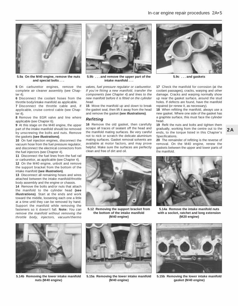
5 On carburettor engines, remove thecomplete air cleaner assembly (see Chap-ter 4).6 Disconnect the coolant hoses from thethrottle body/intake manifold as applicable.7 Disconnect the throttle cable and, ifapplicable, cruise control cable (see Chap-ter 4).8 Remove the EGR valve and line whereapplicable (see Chapter 6).9 At this stage on the M40 engine, the upperpart of the intake manifold should be removedby unscrewing the bolts and nuts. Removethe gaskets (see illustrations).10 On fuel injection engines, disconnect thevacuum hose from the fuel pressure regulator,and disconnect the electrical connectors fromthe fuel injectors (see Chapter 4).11 Disconnect the fuel lines from the fuel railor carburettor, as applicable (see Chapter 4). 12 On the M40 engine, unbolt and removethe support bracket from the bottom of theintake manifold (see illustration).13 Disconnect all remaining hoses and wiresattached between the intake manifold/throttlebody assembly and the engine or chassis.14 Remove the bolts and/or nuts that attachthe manifold to the cylinder head (seeillustrations). Start at the ends and worktoward the middle, loosening each one a littleat a time until they can be removed by hand.Support the manifold while removing thefasteners so it doesn’t fall. Note: You canremove the manifold without removing thethrottle body, injectors, vacuum/thermo
valves, fuel pressure regulator or carburettor.If you’re fitting a new manifold, transfer thecomponents (see Chapter 4) and lines to thenew manifold before it is fitted on the cylinderhead.15 Move the manifold up and down to breakthe gasket seal, then lift it away from the headand remove the gasket (see illustrations).
Refitting16 Remove the old gasket, then carefullyscrape all traces of sealant off the head andthe manifold mating surfaces. Be very carefulnot to nick or scratch the delicate aluminiummating surfaces. Gasket removal solvents areavailable at motor factors, and may provehelpful. Make sure the surfaces are perfectlyclean and free of dirt and oil.
17 Check the manifold for corrosion (at thecoolant passages), cracks, warping and otherdamage. Cracks and warping normally showup near the gasket surface, around the studholes. If defects are found, have the manifoldrepaired (or renew it, as necessary).18 When refitting the manifold, always use anew gasket. Where one side of the gasket hasa graphite surface, this must face the cylinderhead.19 Refit the nuts and bolts and tighten themgradually, working from the centre out to theends, to the torque listed in this Chapter’sSpecifications.20 The remainder of refitting is the reverse ofremoval. On the M40 engine, renew thegaskets between the upper and lower parts ofthe manifold.
In-car engine repair procedures 2A•5
5.9c . . . and gaskets5.9b . . . and remove the upper part of theintake manifold . . .
5.9a On the M40 engine, remove the nutsand special bolts . . .
5.15b Removing the lower intake manifoldgasket (M40 engine)
5.15a Removing the lower intake manifold(M40 engine)
5.14a Remove the intake manifold nutswith a socket, ratchet and long extension
(M20 engine)
5.12 Removing the support bracket fromthe bottom of the intake manifold
(M40 engine)
5.14b Removing the lower intake manifoldnuts (M40 engine)
2A
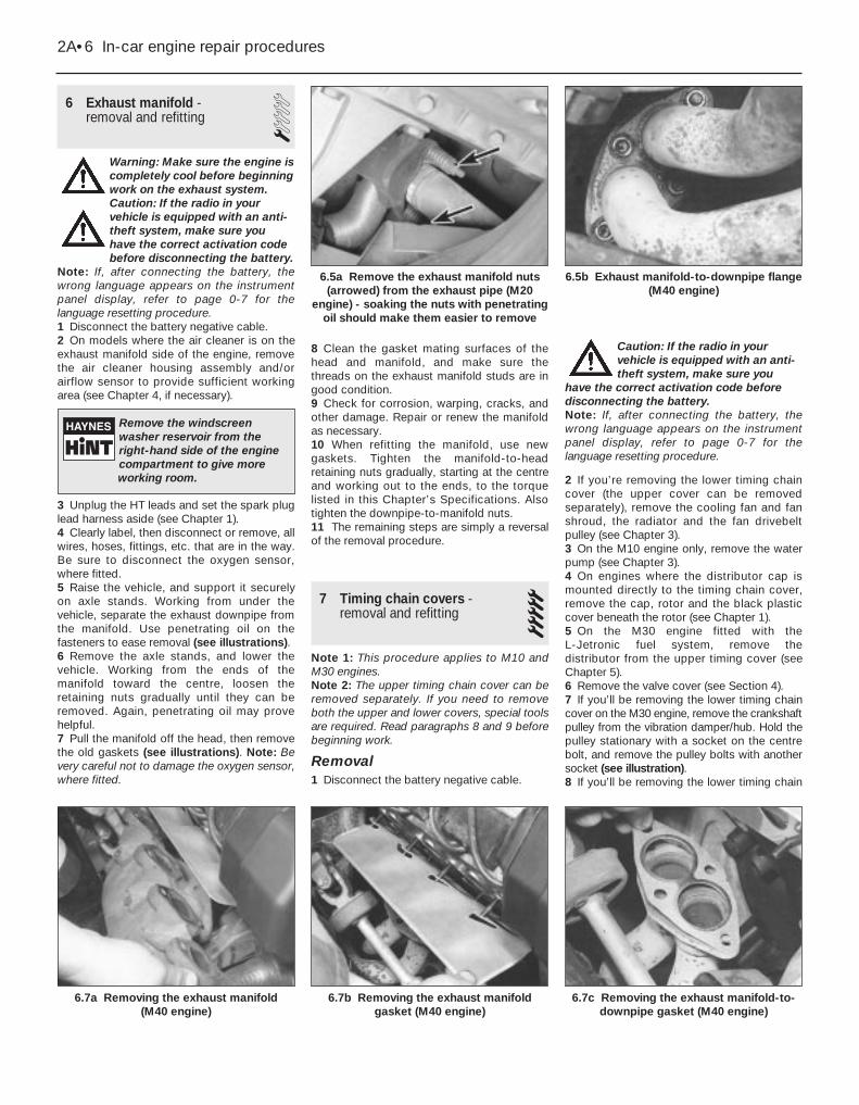
6 Exhaust manifold - removal and refitting 1
Warning: Make sure the engine iscompletely cool before beginningwork on the exhaust system.Caution: If the radio in yourvehicle is equipped with an anti-theft system, make sure youhave the correct activation codebefore disconnecting the battery.
Note: If, after connecting the battery, thewrong language appears on the instrumentpanel display, refer to page 0-7 for thelanguage resetting procedure.1 Disconnect the battery negative cable.2 On models where the air cleaner is on theexhaust manifold side of the engine, removethe air cleaner housing assembly and/orairflow sensor to provide sufficient workingarea (see Chapter 4, if necessary).
3 Unplug the HT leads and set the spark pluglead harness aside (see Chapter 1). 4 Clearly label, then disconnect or remove, allwires, hoses, fittings, etc. that are in the way.Be sure to disconnect the oxygen sensor,where fitted.5 Raise the vehicle, and support it securelyon axle stands. Working from under thevehicle, separate the exhaust downpipe fromthe manifold. Use penetrating oil on thefasteners to ease removal (see illustrations).6 Remove the axle stands, and lower thevehicle. Working from the ends of themanifold toward the centre, loosen theretaining nuts gradually until they can beremoved. Again, penetrating oil may provehelpful.7 Pull the manifold off the head, then removethe old gaskets (see illustrations). Note: Bevery careful not to damage the oxygen sensor,where fitted.
8 Clean the gasket mating surfaces of thehead and manifold, and make sure thethreads on the exhaust manifold studs are ingood condition.9 Check for corrosion, warping, cracks, andother damage. Repair or renew the manifoldas necessary.10 When refitting the manifold, use newgaskets. Tighten the manifold-to-headretaining nuts gradually, starting at the centreand working out to the ends, to the torquelisted in this Chapter’s Specifications. Alsotighten the downpipe-to-manifold nuts.11 The remaining steps are simply a reversalof the removal procedure.
7 Timing chain covers -removal and refitting 5
Note 1: This procedure applies to M10 andM30 engines.Note 2: The upper timing chain cover can beremoved separately. If you need to removeboth the upper and lower covers, special toolsare required. Read paragraphs 8 and 9 beforebeginning work.
Removal1 Disconnect the battery negative cable.
Caution: If the radio in yourvehicle is equipped with an anti-theft system, make sure you
have the correct activation code beforedisconnecting the battery.Note: If, after connecting the battery, thewrong language appears on the instrumentpanel display, refer to page 0-7 for thelanguage resetting procedure.
2 If you’re removing the lower timing chaincover (the upper cover can be removedseparately), remove the cooling fan and fanshroud, the radiator and the fan drivebeltpulley (see Chapter 3).3 On the M10 engine only, remove the waterpump (see Chapter 3).4 On engines where the distributor cap ismounted directly to the timing chain cover,remove the cap, rotor and the black plasticcover beneath the rotor (see Chapter 1).5 On the M30 engine fitted with the L-Jetronic fuel system, remove the distributor from the upper timing cover (seeChapter 5).6 Remove the valve cover (see Section 4).7 If you’ll be removing the lower timing chaincover on the M30 engine, remove the crankshaftpulley from the vibration damper/hub. Hold thepulley stationary with a socket on the centrebolt, and remove the pulley bolts with anothersocket (see illustration).8 If you’ll be removing the lower timing chain
2A•6 In-car engine repair procedures
6.7c Removing the exhaust manifold-to-downpipe gasket (M40 engine)
6.7b Removing the exhaust manifoldgasket (M40 engine)
6.7a Removing the exhaust manifold (M40 engine)
6.5b Exhaust manifold-to-downpipe flange(M40 engine)
6.5a Remove the exhaust manifold nuts(arrowed) from the exhaust pipe (M20
engine) - soaking the nuts with penetratingoil should make them easier to remove
Remove the windscreenwasher reservoir from theright-hand side of the enginecompartment to give moreworking room.

cover, remove the vibration damper/hub bylocking the crankshaft in position andloosening the large centre bolt. Since the boltis on very tight, you’ll need to use anextension bar and socket to break it loose. OnM30 engines, BMW recommends using a 3/4-inch drive socket and extension bar, sincethe bolt is extremely tight on these engines.To lock the crankshaft in place while the boltis being loosened, use BMW special tool No. 11 2 100 (or equivalent).9 On the M10 engine, if the special tool listedin the previous paragraph is not available, youmay try locking the crankshaft by removingthe flywheel/driveplate inspection cover andjamming a wide-bladed screwdriver into thering gear teeth. On the M30 engine, since thebolt is so extremely tight, we don’trecommend substitute methods. Use thecorrect tool. On the M10 engine, after thecentre bolt is removed, it will probably benecessary to use a jaw-type puller to pull thevibration damper off the crankshaft. Positionthe jaws behind the inner pulley groove, andtighten the puller centre bolt very slowly,checking the pulley to make sure it does notget bent or otherwise damaged by the puller.
10 Unscrew the plug and remove the timingchain tensioner spring (see illustration). Thetensioner plunger may come out with thespring. If not, reach down into the hole wherethe tensioner spring was, and remove theplunger. To check the plunger for properoperation, see Section 8.
Caution: The spring is undertension, and this could cause theplug to be ejected from its hole withconsiderable force. Hold thetensioner plug securely as it’s being
unscrewed, and release the spring tensionslowly. 11 On the M30 engine, if you’re removing theupper timing cover, unbolt the thermostat coverand remove the thermostat (see Chapter 3).12 On the M30 engine, if you’re removing thelower timing cover, loosen the alternatormounting bolts, and swing the alternator toone side. Remove the front lower mountingbracket bolt, and loosen the other bolts. Alsounbolt the power steering pump mountingbracket, and move it to one side.13 Remove the bolts and nuts securing theupper timing chain cover to the engine block,and remove the cover. Draw a simple diagramshowing the location of the bolts, so they canbe returned to the same holes from whichthey’re removed. Remove the upper timingchain cover. If it sticks to the engine block, tapit gently with a rubber mallet, or place a pieceof wood against the cover and hit the woodwith a hammer. On the M30 engine fitted withthe L-Jetronic fuel system, remove thedistributor driveshaft.14 Remove the bolts and nuts attaching thelower timing chain cover to the engine block.Be sure to remove the three bolts fromunderneath that connect the front of the sumpto the bottom of the front cover (seeillustration). Loosen the remaining sump bolts.15 Run a sharp, thin knife between the sumpgasket and lower timing chain cover, cuttingthe cover free from the gasket. Be very carefulnot to damage or dirty the gasket, so you canre-use it. 16 Break the lower timing chain cover-to-block gasket seal by tapping the cover with arubber mallet, or with a hammer and block ofwood. Do not prise between the cover and theengine block, as damage to the gasket sealingsurfaces will result.17 Using a scraper, remove all traces of oldgasket material from the sealing surfaces ofthe covers and engine block.
Caution: Be very careful not toscratch or gouge the delicatealuminium surfaces. Also, do notdamage the sump gasket, and
keep it clean. Gasket removal solvents areavailable at motor factors, and may provehelpful. After all gasket material has been
removed, the gasket surfaces can bedegreased by wiping them with a ragdampened with a suitable solvent.
Refitting18 Renew the front oil seals (see Section 11).It’s not wise to take a chance on an old seal,since renewal with the covers removed is veryeasy. Be sure to apply a little oil to the front oilseal lips.19 Apply a film of RTV-type gasket sealant tothe surface of the sump gasket that mateswith the lower timing chain cover. Apply extrabeads of RTV sealant to the edges where thegasket meets the engine block. Note: If thesump gasket is damaged, instead of fitting awhole new gasket, you might try trimming thefront portion of the gasket off at the pointwhere it meets the engine block, then trim offthe front portion of a new sump gasket so it’sexactly the same size. Cover the exposedinside area of the sump with a rag, then cleanall traces of old gasket material off the areawhere the gasket was removed. Attach thenew gasket piece to the sump with contact-cement-type gasket adhesive, then applyRTV-type sealant as described at thebeginning of this paragraph.20 Coat both sides of the new gasket withRTV-type gasket sealant, then attach thelower timing chain cover to the front of theengine. Refit the bolts, and tighten themevenly to the torque listed in this Chapter’sSpecifications. Work from bolt-to-bolt in acriss-cross pattern to be sure they’retightened evenly. Note 1: Tighten the lowercover-to-block bolts first, then tighten thesump-to-cover bolts. If the gasket protrudesabove the cover-to-block joint, or bunches upat the cover-to-sump joint, trim the gasket soit fits correctly. Note 2: After applying RTV-type sealant, reassembly must be completedin about 10 minutes so the RTV won’tprematurely harden.21 Refit the upper timing chain cover in thesame way as the lower cover. If the gasketprotrudes beyond the top of the cover and theengine block, trim off the excess with a razorblade.22 Refitting is otherwise the reverse ofremoval.
In-car engine repair procedures 2A•7
7.14 From underneath the vehicle, removethe three bolts (arrowed) that connect the
cover and the sump
7.10 Unscrew the plug from the timingchain cover, and remove the tensioner
spring and plunger
7.7 Place a socket and ratchet on thecentre bolt to keep the pulley stationary,and use another socket and ratchet toremove the smaller bolts attaching the
pulley to the vibration damper
2A
If the pulley seems to besticking on the crankshaft, itmay help to spray the hubarea with some penetrating
oil, and to gently tap on the hub areawith a hammer.
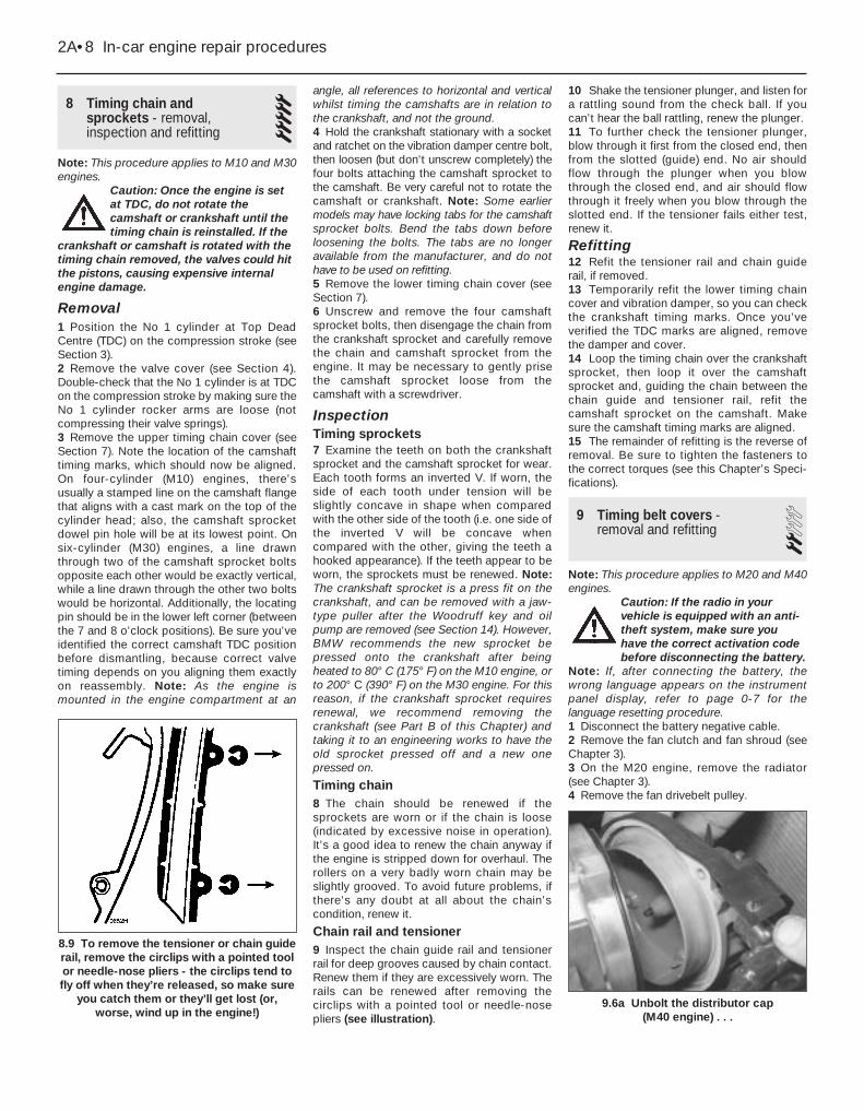
8 Timing chain and sprockets - removal,inspection and refitting
5Note: This procedure applies to M10 and M30engines.
Caution: Once the engine is setat TDC, do not rotate thecamshaft or crankshaft until thetiming chain is reinstalled. If the
crankshaft or camshaft is rotated with thetiming chain removed, the valves could hitthe pistons, causing expensive internalengine damage.
Removal1 Position the No 1 cylinder at Top DeadCentre (TDC) on the compression stroke (seeSection 3).2 Remove the valve cover (see Section 4).Double-check that the No 1 cylinder is at TDCon the compression stroke by making sure theNo 1 cylinder rocker arms are loose (notcompressing their valve springs).3 Remove the upper timing chain cover (seeSection 7). Note the location of the camshafttiming marks, which should now be aligned.On four-cylinder (M10) engines, there’susually a stamped line on the camshaft flangethat aligns with a cast mark on the top of thecylinder head; also, the camshaft sprocketdowel pin hole will be at its lowest point. Onsix-cylinder (M30) engines, a line drawnthrough two of the camshaft sprocket boltsopposite each other would be exactly vertical,while a line drawn through the other two boltswould be horizontal. Additionally, the locatingpin should be in the lower left corner (betweenthe 7 and 8 o’clock positions). Be sure you’veidentified the correct camshaft TDC positionbefore dismantling, because correct valvetiming depends on you aligning them exactlyon reassembly. Note: As the engine ismounted in the engine compartment at an
angle, all references to horizontal and verticalwhilst timing the camshafts are in relation tothe crankshaft, and not the ground.4 Hold the crankshaft stationary with a socketand ratchet on the vibration damper centre bolt,then loosen (but don’t unscrew completely) thefour bolts attaching the camshaft sprocket tothe camshaft. Be very careful not to rotate thecamshaft or crankshaft. Note: Some earliermodels may have locking tabs for the camshaftsprocket bolts. Bend the tabs down beforeloosening the bolts. The tabs are no longeravailable from the manufacturer, and do nothave to be used on refitting.5 Remove the lower timing chain cover (seeSection 7).6 Unscrew and remove the four camshaftsprocket bolts, then disengage the chain fromthe crankshaft sprocket and carefully removethe chain and camshaft sprocket from theengine. It may be necessary to gently prisethe camshaft sprocket loose from thecamshaft with a screwdriver.
InspectionTiming sprockets7 Examine the teeth on both the crankshaftsprocket and the camshaft sprocket for wear.Each tooth forms an inverted V. If worn, theside of each tooth under tension will beslightly concave in shape when comparedwith the other side of the tooth (i.e. one side ofthe inverted V will be concave whencompared with the other, giving the teeth ahooked appearance). If the teeth appear to beworn, the sprockets must be renewed. Note:The crankshaft sprocket is a press fit on thecrankshaft, and can be removed with a jaw-type puller after the Woodruff key and oilpump are removed (see Section 14). However,BMW recommends the new sprocket bepressed onto the crankshaft after beingheated to 80° C (175° F) on the M10 engine, orto 200° C (390° F) on the M30 engine. For thisreason, if the crankshaft sprocket requiresrenewal, we recommend removing thecrankshaft (see Part B of this Chapter) andtaking it to an engineering works to have theold sprocket pressed off and a new onepressed on.
Timing chain8 The chain should be renewed if thesprockets are worn or if the chain is loose(indicated by excessive noise in operation).It’s a good idea to renew the chain anyway ifthe engine is stripped down for overhaul. Therollers on a very badly worn chain may beslightly grooved. To avoid future problems, ifthere’s any doubt at all about the chain’scondition, renew it.
Chain rail and tensioner9 Inspect the chain guide rail and tensionerrail for deep grooves caused by chain contact.Renew them if they are excessively worn. Therails can be renewed after removing thecirclips with a pointed tool or needle-nosepliers (see illustration).
10 Shake the tensioner plunger, and listen fora rattling sound from the check ball. If youcan’t hear the ball rattling, renew the plunger. 11 To further check the tensioner plunger,blow through it first from the closed end, thenfrom the slotted (guide) end. No air shouldflow through the plunger when you blowthrough the closed end, and air should flowthrough it freely when you blow through theslotted end. If the tensioner fails either test,renew it.
Refitting12 Refit the tensioner rail and chain guiderail, if removed.13 Temporarily refit the lower timing chaincover and vibration damper, so you can checkthe crankshaft timing marks. Once you’veverified the TDC marks are aligned, removethe damper and cover.14 Loop the timing chain over the crankshaftsprocket, then loop it over the camshaftsprocket and, guiding the chain between thechain guide and tensioner rail, refit thecamshaft sprocket on the camshaft. Makesure the camshaft timing marks are aligned.15 The remainder of refitting is the reverse ofremoval. Be sure to tighten the fasteners tothe correct torques (see this Chapter’s Speci-fications).
9 Timing belt covers - removal and refitting 2
Note: This procedure applies to M20 and M40engines.
Caution: If the radio in yourvehicle is equipped with an anti-theft system, make sure youhave the correct activation codebefore disconnecting the battery.
Note: If, after connecting the battery, thewrong language appears on the instrumentpanel display, refer to page 0-7 for thelanguage resetting procedure.1 Disconnect the battery negative cable.2 Remove the fan clutch and fan shroud (seeChapter 3).3 On the M20 engine, remove the radiator(see Chapter 3).4 Remove the fan drivebelt pulley.
2A•8 In-car engine repair procedures
9.6a Unbolt the distributor cap (M40 engine) . . .
8.9 To remove the tensioner or chain guiderail, remove the circlips with a pointed toolor needle-nose pliers - the circlips tend tofly off when they’re released, so make sure
you catch them or they’ll get lost (or,worse, wind up in the engine!)
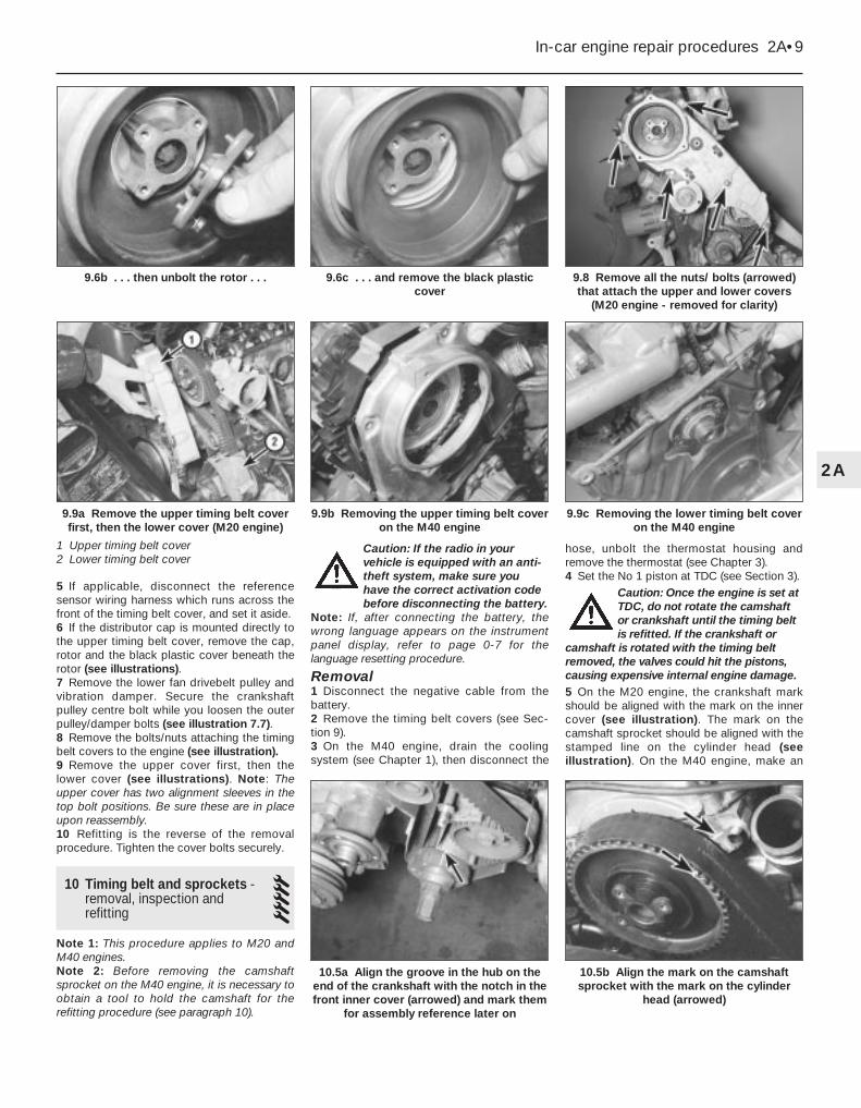
5 If applicable, disconnect the referencesensor wiring harness which runs across thefront of the timing belt cover, and set it aside.6 If the distributor cap is mounted directly tothe upper timing belt cover, remove the cap,rotor and the black plastic cover beneath therotor (see illustrations).7 Remove the lower fan drivebelt pulley andvibration damper. Secure the crankshaftpulley centre bolt while you loosen the outerpulley/damper bolts (see illustration 7.7).8 Remove the bolts/nuts attaching the timingbelt covers to the engine (see illustration).9 Remove the upper cover first, then thelower cover (see illustrations). Note: Theupper cover has two alignment sleeves in thetop bolt positions. Be sure these are in placeupon reassembly.10 Refitting is the reverse of the removalprocedure. Tighten the cover bolts securely.
10 Timing belt and sprockets -removal, inspection andrefitting
5Note 1: This procedure applies to M20 andM40 engines.Note 2: Before removing the camshaftsprocket on the M40 engine, it is necessary toobtain a tool to hold the camshaft for therefitting procedure (see paragraph 10).
Caution: If the radio in yourvehicle is equipped with an anti-theft system, make sure youhave the correct activation codebefore disconnecting the battery.
Note: If, after connecting the battery, thewrong language appears on the instrumentpanel display, refer to page 0-7 for thelanguage resetting procedure.
Removal1 Disconnect the negative cable from thebattery.2 Remove the timing belt covers (see Sec-tion 9).3 On the M40 engine, drain the coolingsystem (see Chapter 1), then disconnect the
hose, unbolt the thermostat housing andremove the thermostat (see Chapter 3).4 Set the No 1 piston at TDC (see Section 3).
Caution: Once the engine is set atTDC, do not rotate the camshaftor crankshaft until the timing beltis refitted. If the crankshaft or
camshaft is rotated with the timing beltremoved, the valves could hit the pistons,causing expensive internal engine damage.5 On the M20 engine, the crankshaft markshould be aligned with the mark on the innercover (see illustration). The mark on thecamshaft sprocket should be aligned with thestamped line on the cylinder head (seeillustration). On the M40 engine, make an
In-car engine repair procedures 2A•9
9.8 Remove all the nuts/ bolts (arrowed)that attach the upper and lower covers
(M20 engine - removed for clarity)
9.6c . . . and remove the black plasticcover
9.6b . . . then unbolt the rotor . . .
9.9c Removing the lower timing belt coveron the M40 engine
9.9b Removing the upper timing belt coveron the M40 engine
10.5b Align the mark on the camshaftsprocket with the mark on the cylinder
head (arrowed)
10.5a Align the groove in the hub on theend of the crankshaft with the notch in thefront inner cover (arrowed) and mark them
for assembly reference later on
9.9a Remove the upper timing belt coverfirst, then the lower cover (M20 engine)
1 Upper timing belt cover2 Lower timing belt cover
2A

alignment mark on the camshaft sprocket andrear timing cover to ensure correct refitting.6 On the M20 engine, loosen the twotensioner roller retaining bolts a little, andpush the tensioner towards the water pump(see illustration). With the timing belt tensionrelieved, re-tighten the retaining bolt.7 On the M40 engine, loosen the tensionerretaining nut, and use an Allen key to rotatethe tensioner clockwise. This will relieve thetension of the timing belt. Tighten theretaining nut to hold the tensioner in its freeposition.8 If the same belt is to be refitted, mark it withan arrow indicating direction of rotation.
Caution: It is not advisable torefit a timing belt which has beenremoved unless it is virtuallynew. On the M40 engine, BMW
recommend that the timing belt isrenewed every time the tensioner roller isreleased.9 Remove the timing belt by slipping it off theroller(s) and the other sprockets (seeillustrations).10 If it’s necessary to remove the camshaftor the intermediate shaft sprocket, remove thesprocket bolt while holding the sprocket toprevent it from moving. To hold the sprocket,wrap it with a piece of an old timing belt(toothed side engaging the sprocket teeth) or
a piece of leather, then hold the sprocketusing a strap spanner. If a strap spanner is notavailable, clamp the ends of the piece of beltor leather tightly together with a pair of grips.Before loosening the bolt, make sure you havethe necessary tool for positioning thecamshaft as described in the followingparagraph (see illustration).
Caution: Do not use the timingbelt you’re planning to refit tohold the sprocket. Also, be sureto hold the camshaft sprocket
very steady, because if it moves more thana few degrees, the valves could hit thepistons.Note: On the M40 engine, the sprocket is notdirectly located on the camshaft with a key, asthe groove in the end of the camshaft allowsthe sprocket to move several degrees in eitherdirection. The retaining bolt locks the sprocketonto a taper after positioning the camshaftwith a special tool. 11 The BMW tool for positioning the camshafton the M40 engine consists of a metal platewhich locates over the square lug near the No1 cylinder lobes on the camshaft - the valvecover must be removed first (seeillustrations). If the BMW tool cannot beobtained, a home-made tool should befabricated out of metal plate. The tool must bemade to hold the square lug on the camshaftat right-angles to the upper face of the cylinderhead (ie the contact face of the valve cover).12 If it’s necessary to remove the crankshaftsprocket, remove the crankshaft hub centrebolt while holding the crankshaft steady.Note: The removal of the crankshaft hubmounting bolt requires a heavy-duty holdingdevice because of the high torque used totighten the bolt. BMW has a special tool,numbered 112150 (M20 engines) or 112170(M40 engines), for this purpose. If this toolcannot be bought or borrowed, check with atool dealer or motor factors for a tool capableof doing the job. Note that the tool number112170 bolts on the rear of the cylinder headand engages with the flywheel ring gear, so itwill only be possible to use this tool if thegearbox has been removed, or if the engine isout of the vehicle (see illustrations). On
2A•10 In-car engine repair procedures
10.12a Home-made tool for holding thecrankshaft stationary while the crankshaft
pulley bolt is being loosened (engineremoved for clarity)
10.11b The BMW camshaft-holding tool inposition on the M40 engine
10.11a The BMW tool for holding thecamshaft in the TDC position on
M40 engines
10.10 Removing the camshaft sprocket onthe M40 engine
10.9b Removing the timing belt from thecamshaft sprocket on the M40 engine
10.9a When removing the timing belt onmodels with a two-piece crankshaft hub,it’s a tight fit to remove it around the hub,
but it’s a lot easier than removing thecrankshaft hub assembly, which is secured
by a very tight bolt
10.6 Loosen the idler pulley bolts(arrowed) to relieve the tension on the
timing belt so it can be removed

models with a two-piece hub, after removingthe outer hub piece, you’ll then need toremove the sprocket with a bolt-type puller(available at most motor factors). When usingthe puller, thread the crankshaft centre bolt inapproximately three turns, and use this as abearing point for the puller’s centre bolt.
Inspection13 Check for a cracked, worn or damagedbelt. Renew it if any of these conditions arefound (see illustrations). Also look at thesprockets for any signs of irregular wear ordamage, indicating the need for renewal.Note: If any parts are to be renewed, checkwith your local BMW dealer parts departmentto be sure compatible parts are used. On M20engines, later sprockets, tensioner rollers andtiming belts are marked “Z 127”. Renewal ofthe timing belt on M20 engines will mean thatthe later belt tensioner should also be fitted, ifnot already done.14 Inspect the idler roller and, on M20engines, the tension spring. Rotate thetensioner roller to be sure it rotates freely, withno noise or play. Note: When fitting a newtiming belt, it is recommended that a newtensioner be fitted also.
Refitting15 On the M20 engine, refit the idler/tensioner/spring so that the timing belt can befitted loosely.16 Refit the sprockets using a reversal of theremoval procedure; tighten the retaining boltsto the specified torque. On the M40 engine,turn the camshaft sprocket clockwise as faras possible within the location groove, thentighten the retaining bolt to an initial torque of1 to 3 Nm at this stage.17 If you are refitting the old belt, make surethe mark made to indicate belt direction ofrotation is pointing the right way (the beltshould rotate in a clockwise direction as youface the front of the engine).18 Refit the timing belt, placing the beltunder the crankshaft sprocket first to get by
the housing. Guide the belt around the othersprocket(s).19 Finally, place the belt over theidler/tensioner rollers.20 On the M20 engine, loosen the tensionerbolts and allow the spring tension to beapplied to the belt.21 On the M20 engine, lightly apply pressurebehind the tensioner to be sure springpressure is being applied to the belt (seeillustration). Don’t tighten the bolts whileapplying pressure; lightly tighten the boltsonly after releasing the tensioner.22 On the M40 engine, unbolt and removethe valve cover, then use the special tool tohold the camshaft in the TDC position (seeparagraph 11).23 On the M40 engine, loosen the tensionerroller retaining nut, and use an Allen key torotate the roller anti-clockwise until the timingbelt is tensioned correctly. The 90°-twistmethod of checking the tension of the timingbelt is not accurate enough for this engine,and it is strongly recommended that thespecial BMW tensioning tool is obtained if atall possible (apply 32 ±2 graduations on thetool) (see illustration). A reasonably accuratealternative can be made using an Allen keyand a spring balance (see illustration). Makesure that the spring balance is positioned asshown, since the tensioner roller is on aneccentric, and different readings will beobtained otherwise. The spring balanceshould be connected 85 mm along the Allenkey, and a force of 2.0 kg (4.4 lb) should be
In-car engine repair procedures 2A•11
10.13a Inspect the timing belt carefully forcracking, as shown here. . .
10.13b . . . and any other damage
10.12c Removing the crankshaft sprocketfrom the front of the crankshaft
10.12b Removing the crankshaft pulleybolt (M40 engine)
10.23b Using a spring balance and Allenkey to adjust the tension of the timing belt
on the M40 engine
Dimension A = 85 mm
10.23a Using the special BMW tool tocheck the tension of the timing belt on the
M40 engine
10.21 On the M20 engine, after the belthas been installed correctly around all
sprockets and the tensioner pulley, lightlyapply pressure to the tensioner, to be sure
the tensioner isn’t stuck and has fullmovement against the timing belt
2A
applied. Tighten the retaining nut to thespecified torque to hold the tensioner in itscorrect position. Note: It is important that thetiming belt is tensioned correctly. If the belt isover-tightened, it will howl, and there is thepossibility of it being damaged. If the belt istoo slack, it may jump on the sprockets.24 Check to make sure the camshaft andcrankshaft timing marks are still aligned (seeillustrations 10.5a and 10.5b).25 Turn the crankshaft clockwise throughtwo complete revolutions. (Remove thecamshaft positioning tool from the M40engine first.)
Caution: This is necessary tostretch the new belt. If not done,the belt tensioner will be tooloose, and damage could result.
26 On the M20 engine, loosen the tensionerroller bolts, then tighten them to the torquelisted in this Chapter’s Specifications.27 On the M40 engine, loosen the tensionerroller retaining nut, and re-adjust the tensionof the timing belt as described in paragraph23. On completion, tighten the tensioner rollerretaining nut, then fully tighten the camshaftsprocket bolt if previously loosened (seeillustration).28 Verify that the timing marks are stillperfectly aligned. If not, remove and refit thetiming belt.29 The remainder of refitting is the reverse ofremoval.
11 Front oil seals - renewal 5Note: Oil seals are fitted with their sealing lipsfacing inwards (towards the engine).
M10 and M30 (timing chain)engines
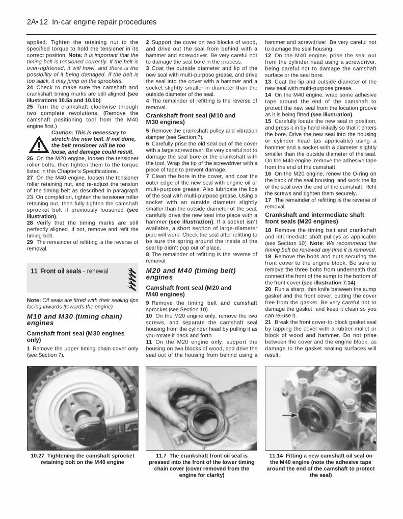
Camshaft front seal (M30 enginesonly)1 Remove the upper timing chain cover only(see Section 7).
2 Support the cover on two blocks of wood,and drive out the seal from behind with ahammer and screwdriver. Be very careful notto damage the seal bore in the process.3 Coat the outside diameter and lip of thenew seal with multi-purpose grease, and drivethe seal into the cover with a hammer and asocket slightly smaller in diameter than theoutside diameter of the seal.4 The remainder of refitting is the reverse ofremoval.
Crankshaft front seal (M10 and M30 engines)5 Remove the crankshaft pulley and vibrationdamper (see Section 7).6 Carefully prise the old seal out of the coverwith a large screwdriver. Be very careful not todamage the seal bore or the crankshaft withthe tool. Wrap the tip of the screwdriver with apiece of tape to prevent damage.7 Clean the bore in the cover, and coat theouter edge of the new seal with engine oil ormulti-purpose grease. Also lubricate the lipsof the seal with multi-purpose grease. Using asocket with an outside diameter slightlysmaller than the outside diameter of the seal,carefully drive the new seal into place with ahammer (see illustration). If a socket isn’tavailable, a short section of large-diameterpipe will work. Check the seal after refitting tobe sure the spring around the inside of theseal lip didn’t pop out of place.8 The remainder of refitting is the reverse ofremoval.
M20 and M40 (timing belt)engines
Camshaft front seal (M20 and M40 engines)9 Remove the timing belt and camshaftsprocket (see Section 10).10 On the M20 engine only, remove the twoscrews, and separate the camshaft sealhousing from the cylinder head by pulling it asyou rotate it back and forth.11 On the M20 engine only, support thehousing on two blocks of wood, and drive theseal out of the housing from behind using a
hammer and screwdriver. Be very careful notto damage the seal housing.12 On the M40 engine, prise the seal outfrom the cylinder head using a screwdriver,being careful not to damage the camshaftsurface or the seal bore.13 Coat the lip and outside diameter of thenew seal with multi-purpose grease.14 On the M40 engine, wrap some adhesivetape around the end of the camshaft toprotect the new seal from the location grooveas it is being fitted (see illustration).15 Carefully locate the new seal in position,and press it in by hand initially so that it entersthe bore. Drive the new seal into the housingor cylinder head (as applicable) using ahammer and a socket with a diameter slightlysmaller than the outside diameter of the seal.On the M40 engine, remove the adhesive tapefrom the end of the camshaft.16 On the M20 engine, renew the O-ring onthe back of the seal housing, and work the lipof the seal over the end of the camshaft. Refitthe screws and tighten them securely.17 The remainder of refitting is the reverse ofremoval.
Crankshaft and intermediate shaftfront seals (M20 engines)18 Remove the timing belt and crankshaftand intermediate shaft pulleys as applicable(see Section 10). Note: We recommend thetiming belt be renewed any time it is removed.19 Remove the bolts and nuts securing thefront cover to the engine block. Be sure toremove the three bolts from underneath thatconnect the front of the sump to the bottom ofthe front cover (see illustration 7.14).20 Run a sharp, thin knife between the sumpgasket and the front cover, cutting the coverfree from the gasket. Be very careful not todamage the gasket, and keep it clean so youcan re-use it. 21 Break the front cover-to-block gasket sealby tapping the cover with a rubber mallet orblock of wood and hammer. Do not prisebetween the cover and the engine block, asdamage to the gasket sealing surfaces willresult.
2A•12 In-car engine repair procedures
11.14 Fitting a new camshaft oil seal onthe M40 engine (note the adhesive tape
around the end of the camshaft to protectthe seal)
11.7 The crankshaft front oil seal ispressed into the front of the lower timing
chain cover (cover removed from theengine for clarity)
10.27 Tightening the camshaft sprocketretaining bolt on the M40 engine

22 Using a scraper, remove all traces of oldgasket material from the sealing surfaces ofthe covers and engine block.
Caution: Be very careful not toscratch or gouge the delicatealuminium surfaces. Also, do notdamage the sump gasket, and
keep it clean. Gasket removal solvents areavailable at motor factors, and may prove helpful. After all gasket material hasbeen removed, the gasket surfaces can be degreased by wiping them with a rag dampened with a suitablesolvent.
23 Support the cover on two blocks of wood,and drive out the seals from behind with ahammer and screwdriver. Be very careful notto damage the seal bores in the process.24 Coat the outside diameters and lips of thenew seals with multi-purpose grease, anddrive the seals into the cover with a hammerand a socket slightly smaller in diameter thanthe outside diameter of the seal.25 Apply a film of RTV-type gasket sealant tothe surface of the sump gasket that mateswith the front cover. Apply extra beads of RTVsealant to the edges where the gasket meetsthe engine block. Note: If the sump gasket isdamaged, instead of fitting a whole newgasket, you might try trimming the frontportion of the gasket off at the point where itmeets the engine block, then trim off the frontportion of a new sump gasket so it’s exactlythe same size. Cover the exposed inside areaof the sump with a rag, then clean all traces ofold gasket material off the area where thegasket was removed. Attach the new gasketpiece to the sump with contact-cement-typegasket adhesive, then apply RTV-type sealantas described at the beginning of thisparagraph.26 Coat both sides of the new gasket withRTV-type gasket sealant, then attach the frontcover to the front of the engine, carefullyworking the seals over the crankshaft andintermediate shaft. Refit the bolts and tightenthem evenly to the torque listed in thisChapter’s Specifications. Work from bolt-to-bolt in a criss-cross pattern, to be sure they’retightened evenly. Note 1: Tighten the frontcover-to-block bolts first, then tighten thesump-to-cover bolts. Note 2: After applyingRTV-type sealant, reassembly must becompleted in about 10 minutes so the RTVwon’t prematurely harden.27 The remainder of refitting is the reverse ofremoval.
Crankshaft front seal (M40 engines)28 Remove the timing belt and crankshaftsprocket (see Section 10).29 Remove the Woodruff key from thegroove in the end of the crankshaft.30 Note the fitted position of the oil seal, thenprise it out from the front cover using ascrewdriver, but take care not to damage thebore of the cover or the surface of the
crankshaft. If the seal is tight, drill two smallholes in the metal end of the seal, and use twoself-tapping screws to pull out the seal. Makesure all remains of swarf are removed.31 Coat the outside diameter and lip of thenew seal with multi-purpose grease, thendrive it into the cover with a hammer and asocket slightly smaller in diameter than theoutside diameter of the seal. Make sure theseal enters squarely.32 The remainder of refitting is the reverse ofremoval. Note that it is recommended that thetiming belt be renewed - see Section 10.
12 Cylinder head - removal and refitting 5
Removal1 Relieve the fuel pressure on all fuel injectionengines (see Chapter 4).2 Disconnect the negative cable from thebattery. Where the battery is located in theengine compartment, the battery may beremoved completely (see Chapter 5).
Caution: If the radio in yourvehicle is equipped with an anti-theft system, make sure youhave the correct activation code
before disconnecting the battery.Note: If, after connecting the battery, thewrong language appears on the instrumentpanel display, refer to page 0-7 for thelanguage resetting procedure.
3 Remove the air cleaner assembly (seeChapter 4).4 Disconnect the wiring from the distributor(mark all wiring for position first, if necessary),and the HT lead from the coil (see Chapter 5).5 Disconnect the lead from the coolanttemperature sender unit (see Chapter 3).6 Disconnect the fuel lines from the fuel rail orcarburettor as applicable (see Chapter 4).7 Drain the cooling system (see Chapter 3).8 Clearly label then disconnect all otherhoses from the throttle body, intake manifold,carburettor and cylinder head, as applicable.9 Disconnect the throttle cable from thethrottle linkage or carburettor (see Chapter 4).10 Disconnect the exhaust manifold from thecylinder head (see Section 6). Depending onthe engine type, It may not be necessary todisconnect the manifold from the exhaustpipe; however, on right-hand-drive models,the steering column intermediate shaft maynot allow the manifold to clear the studs onthe cylinder head.11 Remove or disconnect any remaininghoses or lines from the intake manifold,including the ignition advance vacuum line(s),and the coolant and heater hoses.12 On early carburettor models, disconnectthe wiring from the alternator and startermotor.
13 Remove the intake manifold (see Sec-tion 5). Do not dismantle or remove any fuelinjection system components unless it isabsolutely necessary.14 Remove the fan drivebelt and fan (seeChapter 3).15 Remove the valve cover and gasket (seeSection 4). Remove the semi-circular rubberseal from the front of the cylinder head, wherethis is not incorporated in the valve covergasket.16 Set No 1 piston at Top Dead Centre onthe compression stroke (see Section 3).17 Remove the timing chain or belt (seeSection 8 or 10). Note: If you want to savetime by not removing and refitting the timingbelt or chain and re-timing the engine, you canunfasten the camshaft sprocket and suspendit out of the way - with the belt or chain stillattached - by a piece of rope. Be sure therope keeps firm tension on the belt or chain,so it won’t become disengaged from any ofthe sprockets.18 Loosen the cylinder head bolts a quarter-turn at a time each, in the reverse of thetightening sequence shown (see illustrations12.30a, 12.30b, 12.30c or 12.30d). Do not dismantle or remove the rocker armassembly at this time on M10, M20 and M30engines.19 Remove the cylinder head by lifting itstraight up and off the engine block. Do notprise between the cylinder head and theengine block, as damage to the gasket sealingsurfaces may result. Instead, use a blunt barpositioned in an intake port to gently prise thehead loose.20 Remove any remaining externalcomponents from the head to allow forthorough cleaning and inspection. SeeChapter 2B for cylinder head servicingprocedures. On the M40 engine, remove therubber O-ring from the groove in the top of theoil pump/front end cover housing.
Refitting21 The mating surfaces of the cylinder headand block must be perfectly clean when thehead is refitted.22 Use a gasket scraper to remove all tracesof carbon and old gasket material, then cleanthe mating surfaces with a suitable solvent. Ifthere’s oil on the mating surfaces when thehead is refitted, the gasket may not sealcorrectly, and leaks could develop. Whenworking on the block, stuff the cylinders withclean rags to keep out debris. Use a vacuumcleaner to remove material that falls into thecylinders.23 Check the block and head matingsurfaces for nicks, deep scratches and otherdamage. If the damage is slight, it can beremoved with a file; if it’s excessive,machining may be the only alternative.24 Use a tap of the correct size to chase thethreads in the head bolt holes, then clean theholes with compressed air - make sure that
In-car engine repair procedures 2A•13
2A
nothing (including oil, water, etc) remains inthe holes (see illustration).25 BMW recommend head bolts are renewed,but if the old ones are re-used, mount each boltin a vice, and run a die down the threads toremove corrosion and restore the threads. Dirt,corrosion, sealant and damaged threads willaffect torque readings (see illustration). If thebolts or their threads are damaged, do not re-use the bolts - fit a new set.26 Refit any components removed from thehead prior to cleaning and inspection. On theM40 engine, locate a new rubber O-ring in thegroove in the top of the oil pump/front endcover housing (see illustration).27 Make sure the gasket sealing surfaces of
the engine block and cylinder head are cleanand oil-free. Lay the head gasket in place onthe block, with the manufacturer’s stampedmark facing up (it usually says “UP,” “OBEN”or something similar). Use the dowel pins in thetop of the block to properly locate the gasket.28 Carefully set the cylinder head in placeon the block. Use the dowel pins to properlyalign it. Where the engine is tilted slightly (ieM40 engine) you may find it helpful to fitguide studs to ensure correct positioning ofthe cylinder head on the block. Use two oldhead bolts, one screwed into each end ofthe block. Cut the heads off the bolts, anduse a hacksaw to cut slots in the tops of the bolts so they can be removed once
the cylinder head is in position (seeillustration).29 Fit the cylinder head bolts (seeillustration).30 Tighten the cylinder head bolts, in thesequence shown, to the torque listed in thisChapter’s Specifications (see illustrations).Note that on some engines the final stage oftightening takes place after the engine hasbeen run.31 The remainder of refitting is the reverse ofremoval. Set the valve clearances on M10,M20 and M30 engines (see Chapter 1) beforerefitting the valve cover (check them againafter the engine is warmed-up). Run theengine and check for leaks.
2A•14 In-car engine repair procedures
12.30d Cylinder head bolt TIGHTENINGsequence for M40 (four-cylinder) engines
12.30c Cylinder head bolt TIGHTENINGsequence for M30 (six-cylinder) engines
12.30b Cylinder head bolt TIGHTENINGsequence for M20 (six-cylinder) engines
12.30a Cylinder head bolt TIGHTENINGsequence for M10 (four-cylinder) engines
12.29 Inserting a cylinder head bolt (M40 engine)
12.28 Lowering the cylinder head onto theblock (M40 engine)
12.26 Fitting a new rubber O-ring in thegroove in the top of the oil pump/front end
cover on the M40 engine
12.25 A die should be used to removesealant and corrosion from the head bolt
threads prior to installation
12.24 The cylinder head bolt holes shouldbe cleaned and restored with a tap (be
sure to remove debris from the holes afterthis is done)

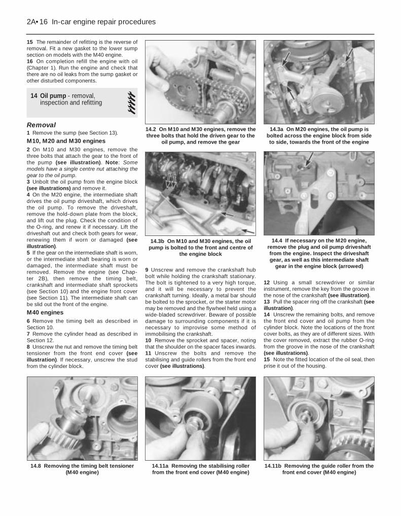
13 Sump - removal and refitting 11 Drain the engine oil (see Chapter 1).2 Raise the front of the vehicle and place itsecurely on axle stands.3 Remove the splash shields from under theengine.4 Where applicable, disconnect the hosesattached to the sump, and move them to oneside (see illustration).5 Where applicable, disconnect the oil levelsensor electrical connector (see illustration).6 Where applicable, remove the cast-aluminium inspection cover that covers therear of the sump (see illustrations).7 On models with the M40 engine, unbolt andremove the lower sump section and removethe gasket (this is necessary for access to thefront mounting bolts). Unscrew the mountingbolt, and pull the oil dipstick tube from thesump (see illustrations). Check the conditionof the O-ring, and renew it if necessary.8 On models with the M40 engine, unscrewthe engine mounting nuts on both sides, thenattach a suitable hoist and lift the enginesufficiently to allow the sump to be removed.As a safety precaution, position axle stands orblocks of wood beneath the engine.9 Remove the bolts securing the sump to the
engine block and front/rear covers (seeillustration).10 Tap on the sump with a soft-facedhammer to break the gasket seal, and lowerthe sump from the engine.11 Using a gasket scraper, scrape off alltraces of the old gasket from the engineblock, the timing chain cover, the rear main oilseal housing, and the sump. Be especiallycareful not to nick or gouge the gasket sealingsurfaces of the timing chain cover and the oilseal housing (they are made of aluminium,and are quite soft).12 Clean the sump with solvent, and dry itthoroughly. Check the gasket sealing surfacesfor distortion. Clean any residue from the
gasket sealing surfaces on the sump andengine with a rag dampened with a suitablesolvent.13 Before refitting the sump, apply a littleRTV-type gasket sealant to the area where thefront and rear covers join the cylinder block..Lay a new sump gasket in place on the block.If necessary, apply more sealant to hold thegasket in place.14 Carefully position the sump in place (donot disturb the gasket) and refit the bolts.Start with the bolts closest to the centre of thesump, and tighten them to the torque listed inthis Chapter’s Specifications, using a criss-cross pattern. Do not overtighten them, orleakage may occur.
In-car engine repair procedures 2A•15
13.5 If applicable, disconnect the oil levelsensor connector at the left side of theengine, down near the power steering
pump mounting bracket
13.4 If applicable, remove the nut securingthe power steering lines to the sump, andmove the lines to one side to allow you to
get at the sump bolts
12.30e Angle-tightening the cylinder headbolts (M40 engine)
13.9 Remove the bolts holding the sumpto the engine block and front cover, as
shown here on a six-cylinder engine
13.7b Removing the oil dipstick tubebracket mounting bolt
13.6b . . . remove the cover to get to allthe sump bolts
13.6a Remove the four inspection coverbolts (arrowed) and . . .
13.7a Main sump retaining bolts accessedafter removal of the lower sump section onthe M40 engine (engine on bench for clarity)
2A
15 The remainder of refitting is the reverse ofremoval. Fit a new gasket to the lower sumpsection on models with the M40 engine.16 On completion refill the engine with oil(Chapter 1). Run the engine and check thatthere are no oil leaks from the sump gasket orother disturbed components.
14 Oil pump - removal,inspection and refitting 5
Removal1 Remove the sump (see Section 13).
M10, M20 and M30 engines2 On M10 and M30 engines, remove thethree bolts that attach the gear to the front ofthe pump (see illustration). Note: Somemodels have a single centre nut attaching thegear to the oil pump.3 Unbolt the oil pump from the engine block(see illustrations) and remove it.4 On the M20 engine, the intermediate shaftdrives the oil pump driveshaft, which drivesthe oil pump. To remove the driveshaft,remove the hold-down plate from the block,and lift out the plug. Check the condition ofthe O-ring, and renew it if necessary. Lift thedriveshaft out and check both gears for wear,renewing them if worn or damaged (seeillustration).5 If the gear on the intermediate shaft is worn,or the intermediate shaft bearing is worn ordamaged, the intermediate shaft must beremoved. Remove the engine (see Chap-ter 2B), then remove the timing belt,crankshaft and intermediate shaft sprockets(see Section 10) and the engine front cover(see Section 11). The intermediate shaft canbe slid out the front of the engine.
M40 engines6 Remove the timing belt as described inSection 10.7 Remove the cylinder head as described inSection 12.8 Unscrew the nut and remove the timing belttensioner from the front end cover (seeillustration). If necessary, unscrew the studfrom the cylinder block.
9 Unscrew and remove the crankshaft hubbolt while holding the crankshaft stationary.The bolt is tightened to a very high torque,and it will be necessary to prevent thecrankshaft turning. Ideally, a metal bar shouldbe bolted to the sprocket, or the starter motormay be removed and the flywheel held using awide-bladed screwdriver. Beware of possibledamage to surrounding components if it isnecessary to improvise some method ofimmobilising the crankshaft.10 Remove the sprocket and spacer, notingthat the shoulder on the spacer faces inwards.11 Unscrew the bolts and remove thestabilising and guide rollers from the front endcover (see illustrations).
12 Using a small screwdriver or similarinstrument, remove the key from the groove inthe nose of the crankshaft (see illustration).13 Pull the spacer ring off the crankshaft (seeillustration).14 Unscrew the remaining bolts, and removethe front end cover and oil pump from thecylinder block. Note the locations of the frontcover bolts, as they are of different sizes. Withthe cover removed, extract the rubber O-ringfrom the groove in the nose of the crankshaft(see illustrations).15 Note the fitted location of the oil seal, thenprise it out of the housing.
2A•16 In-car engine repair procedures
14.11b Removing the guide roller from thefront end cover (M40 engine)
14.11a Removing the stabilising rollerfrom the front end cover (M40 engine)
14.8 Removing the timing belt tensioner(M40 engine)
14.3b On M10 and M30 engines, the oilpump is bolted to the front and centre of
the engine block
14.4 If necessary on the M20 engine,remove the plug and oil pump driveshaftfrom the engine. Inspect the driveshaftgear, as well as this intermediate shaft
gear in the engine block (arrowed)
14.3a On M20 engines, the oil pump isbolted across the engine block from sideto side, towards the front of the engine
14.2 On M10 and M30 engines, remove thethree bolts that hold the driven gear to the
oil pump, and remove the gear

InspectionNote: Considering that a malfunctioning oilpump can easily cause major engine damage,we recommend that the oil pump shouldalways be renewed during engine overhaul,unless it’s in as-new condition.
M10, M20 and M30 engines16 Remove the cover and check the pumpbody, gears or rotors and cover for cracksand wear (especially in the gear or rotorcontact areas).17 Check the strainer to make sure it is notclogged or damaged.18 Lubricate the gears with clean engine oil,then attach the pump cover to the body andtighten the bolts evenly and securely.
19 Before refitting the pump - new, rebuilt ororiginal - on the engine, check it for properoperation. Fill a clean container to a depth ofone inch with fresh engine oil of therecommended viscosity.20 Immerse the oil pump inlet in the oil, andturn the driveshaft anti-clockwise by hand. Asthe shaft is turned, oil should be dischargedfrom the pump outlet.M40 engines21 With the front end cover on the bench,unscrew the bolts and remove the cover plateto expose the oil pump rotors (seeillustrations).22 Identify the rotors for position, thenremove them from the housing (seeillustrations).
23 Clean the housing and the rotorsthoroughly, then refit the rotors, making surethat they are in their previously-notedpositions. The inner rotor must be fitted withthe guide facing the body.24 Using feeler blades, measure theclearance between the oil pump body and theouter rotor, then check the clearance between the outer and inner rotors (seeillustrations).25 If the clearance is not as given in theSpecifications, the complete oil pump andfront end cover should be renewed. If theclearance is within tolerance, remove therotors, then pour a little engine oil into thehousing. Refit the rotors and turn them tospread the oil around.
In-car engine repair procedures 2A•17
14.14a Front end cover and oil pump inposition on the front of the M40 engine
14.13 Removing the spacer ring from thefront of the crankshaft
14.12 Removing the key from the groovein the nose of the crankshaft (M40 engine)
14.24a Measuring the clearance betweenthe oil pump body and the outer rotor
(M40 engine)
14.22b . . . and outer rotor from the oilpump (M40 engine)
14.22a Removing the inner rotor . . .
14.21b . . . and remove the oil pump cover(M40 engine)
14.21a Unscrew the bolts . . .14.14b Extract the rubber O-ring from thegroove in the nose of the crankshaft
(M40 engine)
2A

26 Refit the cover plate and tighten the boltsto the specified torque.27 To check the pressure relief valve, extractthe circlip and remove the sleeve, spring andpiston. Check that the length of the spring isas given in the Specifications (seeillustrations). Reassemble the pressure reliefvalve using a reversal of the dismantlingprocedure.
Refitting
M10, M20 and M30 engines28 Make sure the mounting surfaces areclean, then insert the pump into the engineblock recess. Refit the bolts and tighten themto the torque specified at the beginning of thisChapter.29 Refitting is the reverse of removal.
M40 engines30 Clean the mating surfaces, then refit thefront end cover and oil pump to the cylinderblock, together with a new gasket (seeillustration). Tighten the bolts to the specified torque. Note that there are two sizesof bolts, and they have different torquesettings.31 Fit the spacer ring on the front of thecrankshaft.32 Apply engine oil to the lips of the new oilseal, then press it into the housing to itspreviously-noted position. To ensure the oilseal enters the housing squarely, use a largesocket and the crankshaft pulley bolt to pull itinto position (see illustration).33 Refit the key to the groove in the nose ofthe crankshaft.
34 Refit the stabilising roller to the front endcover, and tighten the bolt.35 Refit the sprocket, spacer and crankshaftpulley bolt. Tighten the bolt to the specifiedtorque while holding the crankshaft stationaryusing one of the methods previouslydescribed.36 Refit the timing belt tensioning roller, butdo not tighten the bolt at this stage.37 Refit the cylinder head as described inSection 12.38 Refit the timing belt as described inSection 10.39 Refit the sump (see Section 13).
15 Flywheel/driveplate - removal and refitting 3
1 Remove the transmission (on vehicles withmanual transmission, see Chapter 7A; onvehicles with automatic transmission, seeChapter 7B).2 On vehicles with manual transmission,remove the clutch (see Chapter 8).3 Where necessary, mark the relationship ofthe flywheel/driveplate to the crankshaft, so itcan be refitted the same way. 4 The flywheel/driveplate is attached to therear of the crankshaft with eight bolts. Loosenand remove the bolts, then separate it from
2A•18 In-car engine repair procedures
14.32 Using a large socket and thecrankshaft pulley bolt to pull the oil seal
into the housing (M40 engine)14.30 Locating a new gasket on the front
of the cylinder block (M40 engine)14.27e Checking the length of the
pressure relief valve spring (M40 engine)
14.27d . . . and piston14.27c . . . spring . . .
14.27b . . . and remove the sleeve . . .14.27a Extract the circlip from the oilpump (M40 engine) . . .
14.24b Measuring the clearance betweenthe oil pump outer and inner rotors
(M40 engine)
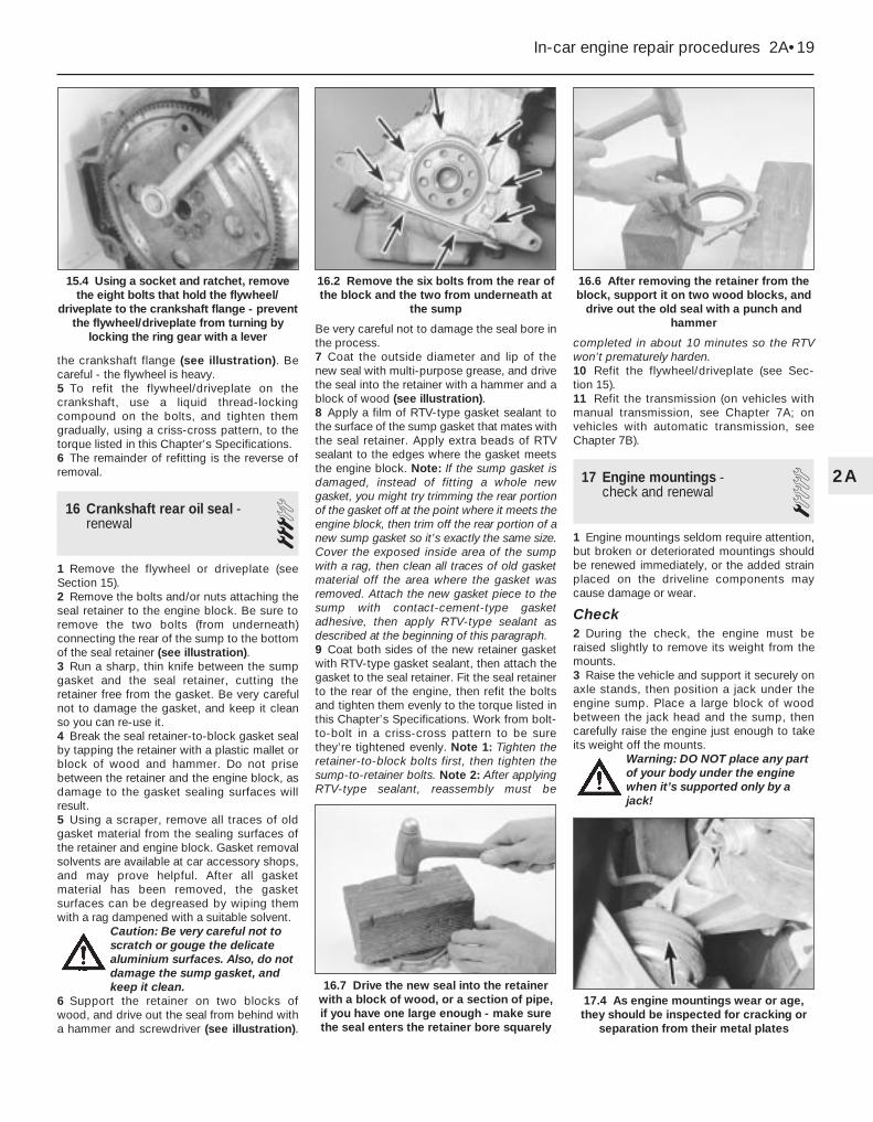
the crankshaft flange (see illustration). Becareful - the flywheel is heavy.5 To refit the flywheel/driveplate on thecrankshaft, use a liquid thread-lockingcompound on the bolts, and tighten themgradually, using a criss-cross pattern, to thetorque listed in this Chapter’s Specifications.6 The remainder of refitting is the reverse ofremoval.
16 Crankshaft rear oil seal -renewal 3
1 Remove the flywheel or driveplate (seeSection 15).2 Remove the bolts and/or nuts attaching theseal retainer to the engine block. Be sure toremove the two bolts (from underneath)connecting the rear of the sump to the bottomof the seal retainer (see illustration).3 Run a sharp, thin knife between the sumpgasket and the seal retainer, cutting theretainer free from the gasket. Be very carefulnot to damage the gasket, and keep it cleanso you can re-use it. 4 Break the seal retainer-to-block gasket sealby tapping the retainer with a plastic mallet orblock of wood and hammer. Do not prisebetween the retainer and the engine block, asdamage to the gasket sealing surfaces willresult.5 Using a scraper, remove all traces of oldgasket material from the sealing surfaces ofthe retainer and engine block. Gasket removalsolvents are available at car accessory shops,and may prove helpful. After all gasketmaterial has been removed, the gasketsurfaces can be degreased by wiping themwith a rag dampened with a suitable solvent.
Caution: Be very careful not toscratch or gouge the delicatealuminium surfaces. Also, do notdamage the sump gasket, andkeep it clean.
6 Support the retainer on two blocks ofwood, and drive out the seal from behind witha hammer and screwdriver (see illustration).
Be very careful not to damage the seal bore inthe process.7 Coat the outside diameter and lip of thenew seal with multi-purpose grease, and drivethe seal into the retainer with a hammer and ablock of wood (see illustration).8 Apply a film of RTV-type gasket sealant tothe surface of the sump gasket that mates withthe seal retainer. Apply extra beads of RTVsealant to the edges where the gasket meetsthe engine block. Note: If the sump gasket isdamaged, instead of fitting a whole newgasket, you might try trimming the rear portionof the gasket off at the point where it meets theengine block, then trim off the rear portion of anew sump gasket so it’s exactly the same size.Cover the exposed inside area of the sumpwith a rag, then clean all traces of old gasketmaterial off the area where the gasket wasremoved. Attach the new gasket piece to thesump with contact-cement-type gasketadhesive, then apply RTV-type sealant asdescribed at the beginning of this paragraph.9 Coat both sides of the new retainer gasketwith RTV-type gasket sealant, then attach thegasket to the seal retainer. Fit the seal retainerto the rear of the engine, then refit the boltsand tighten them evenly to the torque listed inthis Chapter’s Specifications. Work from bolt-to-bolt in a criss-cross pattern to be surethey’re tightened evenly. Note 1: Tighten theretainer-to-block bolts first, then tighten thesump-to-retainer bolts. Note 2: After applyingRTV-type sealant, reassembly must be
completed in about 10 minutes so the RTVwon’t prematurely harden.10 Refit the flywheel/driveplate (see Sec-tion 15).11 Refit the transmission (on vehicles withmanual transmission, see Chapter 7A; onvehicles with automatic transmission, seeChapter 7B).
17 Engine mountings - check and renewal 1
1 Engine mountings seldom require attention,but broken or deteriorated mountings shouldbe renewed immediately, or the added strainplaced on the driveline components maycause damage or wear.
Check2 During the check, the engine must beraised slightly to remove its weight from themounts.3 Raise the vehicle and support it securely onaxle stands, then position a jack under theengine sump. Place a large block of woodbetween the jack head and the sump, thencarefully raise the engine just enough to takeits weight off the mounts.
Warning: DO NOT place any partof your body under the enginewhen it’s supported only by ajack!
In-car engine repair procedures 2A•19
16.6 After removing the retainer from theblock, support it on two wood blocks, and
drive out the old seal with a punch andhammer
16.2 Remove the six bolts from the rear ofthe block and the two from underneath at
the sump
15.4 Using a socket and ratchet, removethe eight bolts that hold the flywheel/
driveplate to the crankshaft flange - preventthe flywheel/driveplate from turning by
locking the ring gear with a lever
17.4 As engine mountings wear or age,they should be inspected for cracking or
separation from their metal plates
16.7 Drive the new seal into the retainerwith a block of wood, or a section of pipe,if you have one large enough - make surethe seal enters the retainer bore squarely
2A
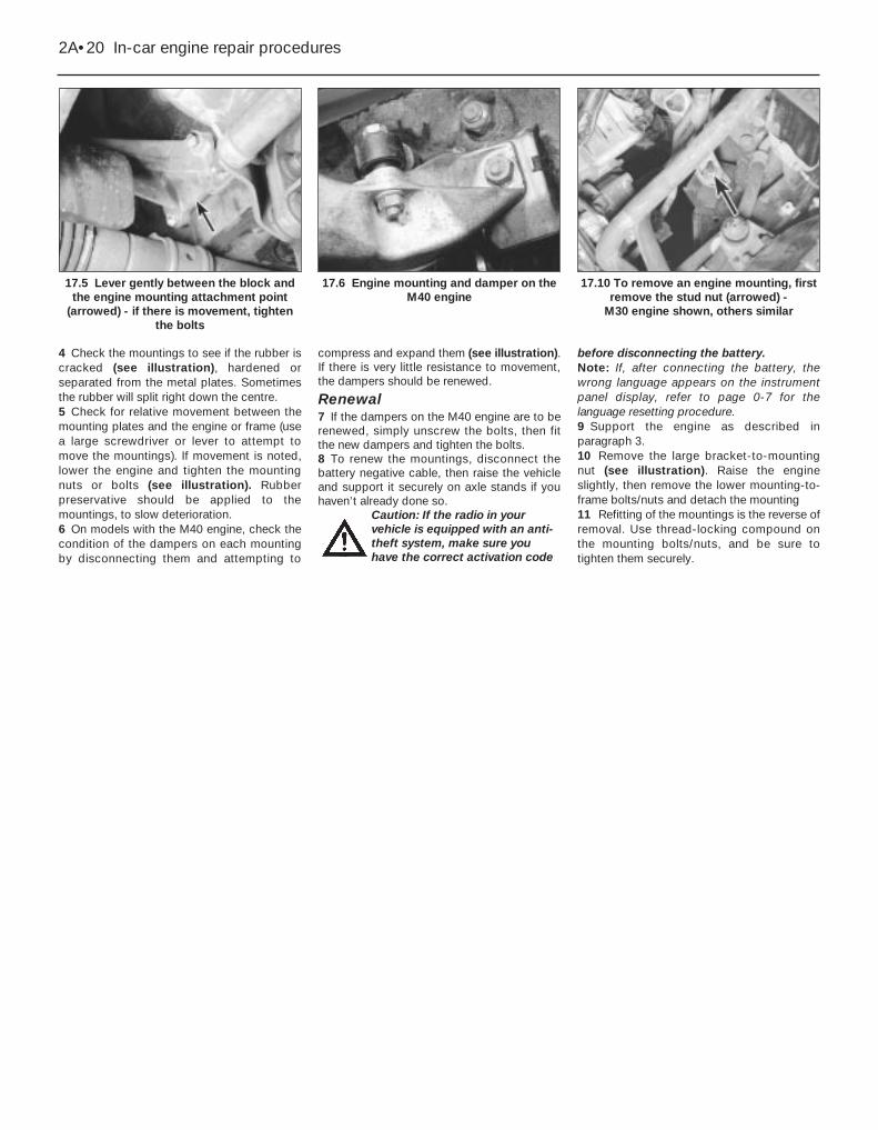
4 Check the mountings to see if the rubber iscracked (see illustration), hardened orseparated from the metal plates. Sometimesthe rubber will split right down the centre.5 Check for relative movement between themounting plates and the engine or frame (usea large screwdriver or lever to attempt tomove the mountings). If movement is noted,lower the engine and tighten the mountingnuts or bolts (see illustration). Rubberpreservative should be applied to themountings, to slow deterioration.6 On models with the M40 engine, check thecondition of the dampers on each mountingby disconnecting them and attempting to
compress and expand them (see illustration).If there is very little resistance to movement,the dampers should be renewed.
Renewal7 If the dampers on the M40 engine are to berenewed, simply unscrew the bolts, then fitthe new dampers and tighten the bolts.8 To renew the mountings, disconnect thebattery negative cable, then raise the vehicleand support it securely on axle stands if youhaven’t already done so.
Caution: If the radio in yourvehicle is equipped with an anti-theft system, make sure youhave the correct activation code
before disconnecting the battery.Note: If, after connecting the battery, thewrong language appears on the instrumentpanel display, refer to page 0-7 for thelanguage resetting procedure.9 Support the engine as described inparagraph 3.10 Remove the large bracket-to-mountingnut (see illustration). Raise the engineslightly, then remove the lower mounting-to-frame bolts/nuts and detach the mounting11 Refitting of the mountings is the reverse ofremoval. Use thread-locking compound onthe mounting bolts/nuts, and be sure totighten them securely.
2A•20 In-car engine repair procedures
17.10 To remove an engine mounting, firstremove the stud nut (arrowed) -
M30 engine shown, others similar
17.6 Engine mounting and damper on theM40 engine
17.5 Lever gently between the block andthe engine mounting attachment point
(arrowed) - if there is movement, tightenthe bolts