CHAPTER 2 OPERATOR INSTRUCTIONS - BOHFPU€¦ · MODELS FPU-8-4/BOH-CARGO-12-3 & FPU-20-3 BOH FPU...
54
BOH-PM-07-2 © 2016 BOH Environmental LLC Chapter 2 Rev. 7.00 FPU ® SYSTEMS OPERATION MANUAL (INCLUDING REPAIR PARTS & SPECIAL TOOL LIST) MODELS FPU-8-4/BOH-CARGO-12-3 & FPU-20-3 BOH FPU Field Pack-up Units CHAPTER 2 OPERATOR INSTRUCTIONS
Transcript of CHAPTER 2 OPERATOR INSTRUCTIONS - BOHFPU€¦ · MODELS FPU-8-4/BOH-CARGO-12-3 & FPU-20-3 BOH FPU...
BOH-PM-07-2 © 2016 BOH Environmental LLC Chapter 2 Rev. 7.00
FPU® SYSTEMS OPERATION MANUAL (INCLUDING REPAIR PARTS & SPECIAL TOOL LIST)
MODELS FPU-8-4/BOH-CARGO-12-3 & FPU-20-3 BOH FPU Field Pack-up Units
CHAPTER 2
OPERATOR INSTRUCTIONS

BOH-PM-07-2 © 2016 BOH Environmental LLC Chapter 2 Rev. 7.00
This page was intentionally left blank
0005 00
BOH-PM-07-2 Chapter 2 Rev. 7.00
0005 00-1
OPERATOR INSTRUCTIONS
FPU® SYSTEMS OPERATION MANUAL (INCLUDING REPAIR PARTS & SPECIAL TOOL LIST)
MODELS FPU-8-4/BOH-CARGO-12-3 & FPU-20-3 BOH FPU Field Pack-up Units
PREPARATION FOR MOVEMENT
INITIAL SETUP: FPU Packed out Maintenance Level Personnel Required
Operator/Crew Two (plus one supervisor)
PREPARATION FOR MOVEMENT
This work package provides step-by-step instructions for the download, set-up and moving of the FPU containers.
WARNING
If a container is dropped during transit movement of any kind, extreme care should be taken when opening the doors to preclude material from falling on and injuring personnel.
Site Requirements
WARNING
Container must be operated on level ground. To maintain control, consider the ground surface conditions for adequate traction, such as mud, snow, ice, sand.
If the container is transported on the HEMTT-LHS truck or PLS trailer, the selected site must have a minimum of 50 ft. x 30 ft. of flat level, open space to provide setup space for the container. Care should be taken to ensure that no overhead obstructions interfere with the offload of the container from the HEMTT.
CAUTION
Flood plain conditions should be considered since the containers have vent holes for the ventilation system that are not designed to withstand flooding. If in doubt, consult the operations supervisor or commander.
0005 00
BOH-PM-07-2 Chapter 2 Rev. 7.00
0005 00-2
PREPARING FPU FOR USE The FPU is designed for a ground-based operation, never attempt to access the containers when the containers are on any transporting equipment or not downloaded and established in an operational site. Once downloaded from the HEMTT truck or trailer, the FPU is ready for immediate use in most circumstances. If delivered as separated FPU-8-4 and BOH-CARGO-12-3 foot containers, they must be connected before loading on the HEMTT vehicle.
CAUTION
FPU-20-3 containers (modified) beginning with serial number AC15002003-002499 (manufactured September 2016) are compatible with Enhanced Containerized Handling Units (ECHU) in FLATRACK MODE that are installed on LHS and PLS vehicles. FPU-20-3 containers manufactured prior to this serial number and FPU-8-4/BOH-CARGO-12-3 containers are not ECHU-compatible.
OPERATION OF ROOF ACCESS SYSTEM The Roof Access System consists of seven retractable steps, on the end of the BOH-CARGO-12-3, FPU-8-4 and the FPU-20-3 with handles recessed in the roof for three-point control while climbing.
WARNING
Fall hazards exist when climbing onto, returning from or working from the top of the container. Always maintain three points of contact to the ladder and FPU container when climbing onto the FPU container. Never move, step, or walk backwards when working on top of the system. All movement should be in the forward direction. A fall can occur if the worker loses concentration and steps backwards off of the edge. Stand erect only if necessary and only away from the edge. Working from a kneeling position helps reduce the threat of a fall.
BOH FPU-8-4/BOH-CARGO-12-3 and FPU-20-3 containers are marked with the following ISO marking. Its meaning is provided below:
WARNING
Overhead power lines and obstructions can cause serious injury or damage to property. Forklift operators, truck drivers and ground guides should always clear overhead when loading, unloading or accessing the roof of the containers.

0005 00
BOH-PM-07-2 Chapter 2 Rev. 7.00
0005 00-3
RETRACTABLE
STEP
FPU-8-4 BOH-CARGO-12-3 and FPU-20-3
ROOF ACCESS SYSTEM
ROOF ACCESS HANDLES
0005 00
BOH-PM-07-2 Chapter 2 Rev. 7.00
0005 00-4
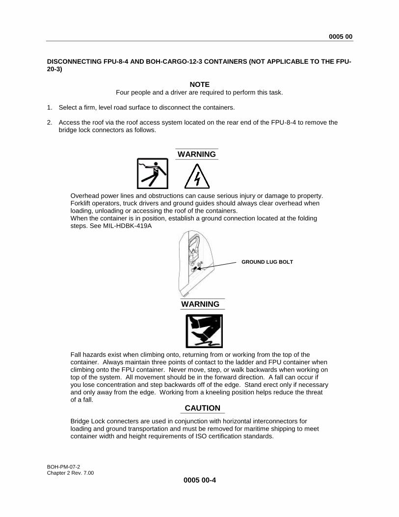
DISCONNECTING FPU-8-4 AND BOH-CARGO-12-3 CONTAINERS (NOT APPLICABLE TO THE FPU-20-3)
NOTE Four people and a driver are required to perform this task.
1. Select a firm, level road surface to disconnect the containers. 2. Access the roof via the roof access system located on the rear end of the FPU-8-4 to remove the
bridge lock connectors as follows.
WARNING
Overhead power lines and obstructions can cause serious injury or damage to property. Forklift operators, truck drivers and ground guides should always clear overhead when loading, unloading or accessing the roof of the containers. When the container is in position, establish a ground connection located at the folding steps. See MIL-HDBK-419A
WARNING
Fall hazards exist when climbing onto, returning from or working from the top of the container. Always maintain three points of contact to the ladder and FPU container when climbing onto the FPU container. Never move, step, or walk backwards when working on top of the system. All movement should be in the forward direction. A fall can occur if you lose concentration and step backwards off of the edge. Stand erect only if necessary and only away from the edge. Working from a kneeling position helps reduce the threat of a fall.
CAUTION
Bridge Lock connecters are used in conjunction with horizontal interconnectors for loading and ground transportation and must be removed for maritime shipping to meet container width and height requirements of ISO certification standards.
GROUND LUG BOLT
0005 00
BOH-PM-07-2 Chapter 2 Rev. 7.00
0005 00-5
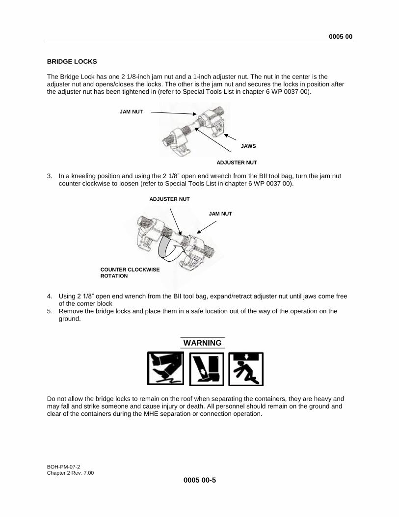
BRIDGE LOCKS The Bridge Lock has one 2 1/8-inch jam nut and a 1-inch adjuster nut. The nut in the center is the adjuster nut and opens/closes the locks. The other is the jam nut and secures the locks in position after the adjuster nut has been tightened in (refer to Special Tools List in chapter 6 WP 0037 00).
3. In a kneeling position and using the 2 1/8” open end wrench from the BII tool bag, turn the jam nut
counter clockwise to loosen (refer to Special Tools List in chapter 6 WP 0037 00).
4. Using 2 1/8” open end wrench from the BII tool bag, expand/retract adjuster nut until jaws come free
of the corner block 5. Remove the bridge locks and place them in a safe location out of the way of the operation on the
ground.
WARNING
Do not allow the bridge locks to remain on the roof when separating the containers, they are heavy and may fall and strike someone and cause injury or death. All personnel should remain on the ground and clear of the containers during the MHE separation or connection operation.
COUNTER CLOCKWISE
ROTATION
JAM NUT
JAWS
ADJUSTER NUT
ADJUSTER NUT
JAM NUT
0005 00
BOH-PM-07-2 Chapter 2 Rev. 7.00
0005 00-6
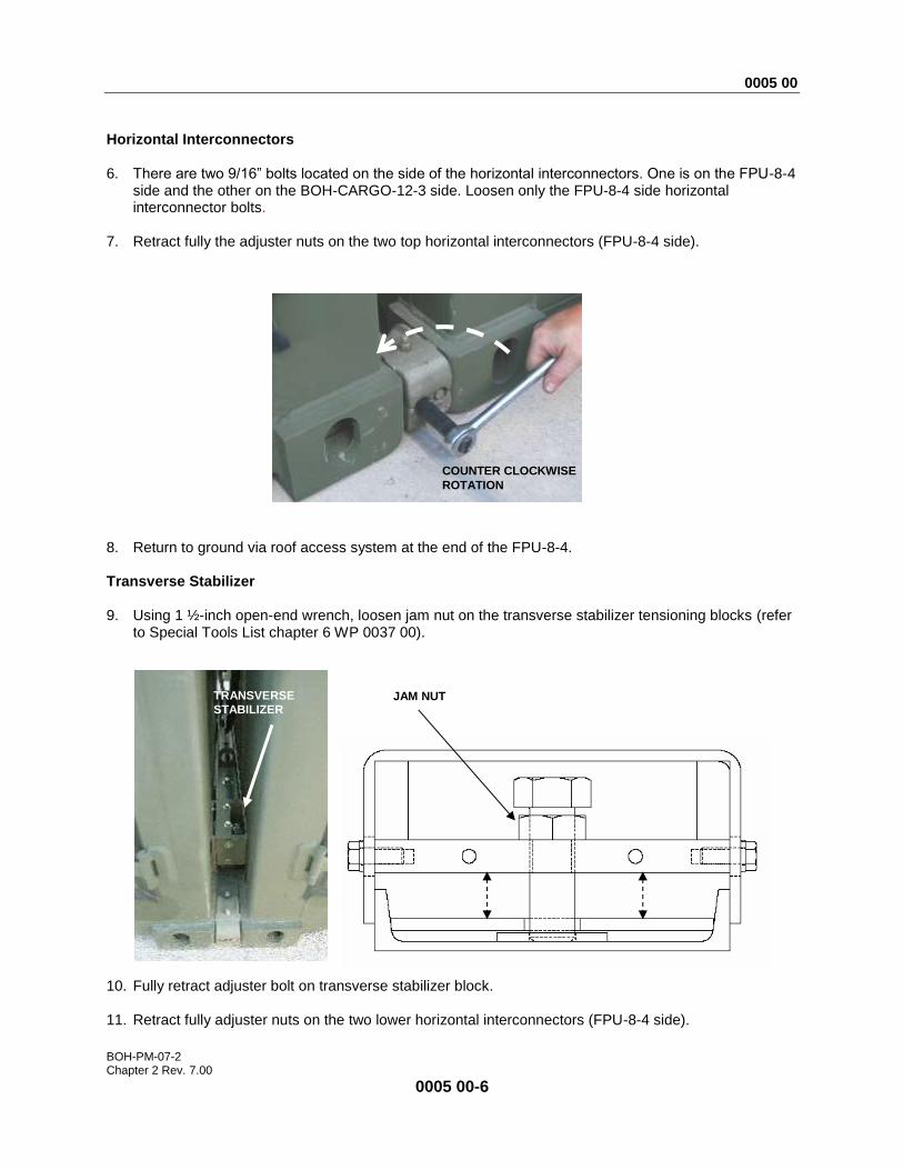
Horizontal Interconnectors 6. There are two 9/16” bolts located on the side of the horizontal interconnectors. One is on the FPU-8-4
side and the other on the BOH-CARGO-12-3 side. Loosen only the FPU-8-4 side horizontal interconnector bolts.
7. Retract fully the adjuster nuts on the two top horizontal interconnectors (FPU-8-4 side).
8. Return to ground via roof access system at the end of the FPU-8-4. Transverse Stabilizer 9. Using 1 ½-inch open-end wrench, loosen jam nut on the transverse stabilizer tensioning blocks (refer
to Special Tools List chapter 6 WP 0037 00).
10. Fully retract adjuster bolt on transverse stabilizer block. 11. Retract fully adjuster nuts on the two lower horizontal interconnectors (FPU-8-4 side).
JAM NUT
FPU 8-4 SIDE
TRANSVERSE
STABILIZER
COUNTER CLOCKWISE
ROTATION
0005 00
BOH-PM-07-2 Chapter 2 Rev. 7.00
0005 00-7
12. If using a HEMTT, attach the loading hook to the bail bar on BOH-CARGO-12-3. Ensure the HEMTT is in a straight line with the container to prevent cocking.
13. Lift slightly until front end is approximately 1-inch off the ground, and pull forward until the loading rail
adapters are completely clear of the loading rails of both containers, and the containers are at least 4-feet apart.
14. Lower and disconnect from HEMTT.
NOTE The transverse stabilizer may bind at this point and could prevent the containers from coming apart. If this happens the operator will have to push the containers back together and retry pulling them apart until successful. Hint: You can assist this operation by using a 2 X 4 board or equivalent to pry open the sticking side of the transverse stabilizer.
15. If using a forklift or other vehicle as listed in the table MHE recommended column in chapter 1 page
0003 00-5, to pull FPU-8-4 from the BOH-CARGO-12-3, attach a chain from the towing vehicle to both of the bottom two ISO blocks on the rear of FPU-8-4.
16. Ensure the towing vehicle is in a straight line with the container and that chain spacing is equal on
both sides to prevent cocking. 17. Slowly pull forward until containers are separated and the loading rail adapters are completely clear
of the loading rails of both containers (containers are at least 4-feet apart).
NOTE The transverse stabilizer may bind at this point and could prevent the containers from coming apart. If this happens the operator will have to push the containers back together with forklift using approved MHE procedures and retry pulling them apart until successful. You can assist this operation by using a 2 X 4 board or equivalent to pry open the sticking side of the transverse stabilizer.
18. Using the 1 1/8-inch socket, ½-inch drive flex head wrench and 2 ½-inch long extension (refer to Special Tools List chapter 6 WP 0037 00), disconnect the transversal stabilizer cross bar from the loading rail connectors.
19. Return to the roof via the roof access system located on the roller end of the BOH-CARGO-12-3 to
remove the upper horizontal interconnectors. 20. While supporting the horizontal interconnector, completely retract adjuster nuts on the two upper
horizontal interconnectors (BOH-CARGO-12-3 side), then remove and store in a safe place. 21. Return to ground via roof access system at the end of the BOH-CARGO-12-3. 22. Completely retract adjuster nuts on the two lower horizontal interconnectors (BOH-CARGO-12-3) and
remove and store in a safe place. 23. Using suitable MHE, raise end of the container still retaining loading rail connectors slightly off the
ground (approximately 1-inch). 24. Slide both of the loading rail connectors from the loading rails, remove the interconnectors and store
in a safe place.

0005 00
BOH-PM-07-2 Chapter 2 Rev. 7.00
0005 00-8
CONNECTING FPU-8-4/BOH-CARGO-12-3 CONTAINERS Refer to Components of End Items (COEI) and Basic Issue Items (BII) List chapter 6 WP 0040 00.
CAUTION
Bridge lock connecters are used in conjunction with ISO horizontal interconnectors for loading and transportation, but must be removed for maritime shipping to meet ISO certification standards.
BOH FPU-8-4 and BOH-CARGO-12-3 containers are connected using four horizontal interconnectors on the ISO corner blocks of each container, two bridge lock connecters at the top of the ISO blocks and the loading rail connector between the containers.
BRIDGE LOCK
LOADING RAIL
CONNECTOR
HORIZONTAL
INTERCONNECTOR
HORIZONTAL
INTERCONNECTORS
BRIDGE LOCKS

0005 00
BOH-PM-07-2 Chapter 2 Rev. 7.00
0005 00-9
INSTALLING THE LOADING RAIL CONNECTOR ASSEMBLY & HORIZONTAL INTERCONNECTORS BETWEEN FPU-8-4 AND BOH-CARGO-12-3 CONTAINERS (NOT APPLICABLE FOR FPU-20-3 CONTAINERS)
WARNING
Ground guides and the MHE operators must maintain direct line of sight and insure that personnel are clear of the containers during this operation. All personnel should remain on the ground and clear of the containers during the MHE separation or connection operation.
DRAIN HOLES
LOADING RAIL CONNECTOR ASSEMBLY
CURB SIDE CONTAINER TENSIONING
BLOCK
TRANSVERSAL STABILIZER
TRANSVERSAL STABILIZER
CHANNEL CROSS MEMBER CONTAINER
TENSIONING BLOCK
LOADING RAIL CONNECTOR ASSEMBLY
STREET SIDE
DIRECT LINE OF SIGHT
DIRECT LINE OF SIGHT
GROUND GUIDE
GROUND GUIDE
0005 00
BOH-PM-07-2 Chapter 2 Rev. 7.00
0005 00-10
HORIZONTAL INTERCONNECTORS 1. Select only a firm level road surface to connect the containers. Align the container ends to be
connected. Leave about four feet between the containers to allow working space for attaching the container connectors.
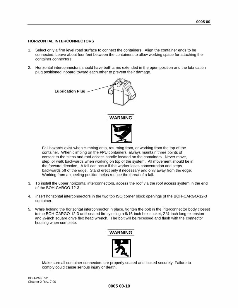
2. Horizontal interconnectors should have both arms extended in the open position and the lubrication plug positioned inboard toward each other to prevent their damage.
WARNING
Fall hazards exist when climbing onto, returning from, or working from the top of the container. When climbing on the FPU containers, always maintain three points of contact to the steps and roof access handle located on the containers. Never move, step, or walk backwards when working on top of the system. All movement should be in the forward direction. A fall can occur if the worker loses concentration and steps backwards off of the edge. Stand erect only if necessary and only away from the edge. Working from a kneeling position helps reduce the threat of a fall.
3. To install the upper horizontal interconnectors, access the roof via the roof access system in the end of the BOH-CARGO-12-3.
4. Insert horizontal interconnectors in the two top ISO corner block openings of the BOH-CARGO-12-3 container.
5. While holding the horizontal interconnector in place, tighten the bolt in the interconnector body closest to the BOH-CARGO-12-3 until seated firmly using a 9/16-inch hex socket, 2 ½-inch long extension and ½-inch square drive flex head wrench. The bolt will be recessed and flush with the connector housing when complete.
WARNING
Make sure all container connectors are properly seated and locked securely. Failure to comply could cause serious injury or death.
Lubrication Plug
0005 00
BOH-PM-07-2 Chapter 2 Rev. 7.00
0005 00-11
6. After the (2) upper horizontal interconnectors are secured in place, climb down from the roof via roof access system.
7. Insert horizontal interconnectors into the two lower ISO corner block openings in the BOH-CARGO-12-3 container.
8. While holding the horizontal interconnector in place, tighten the bolt in the interconnector body closest to the BOH-CARGO-12-3 until seated firmly using a 9/16-inch Hex Socket, 2 ½-inch long extension and ½-inch square drive flex head wrench. The bolt will be recessed and flush with the connector housing when complete.
WARNING
Make sure all container connectors are properly seated and locked securely. Failure to comply could cause serious injury or death.
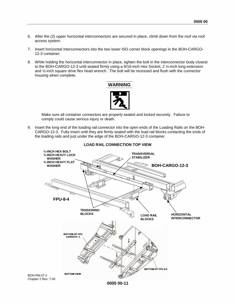
9. Insert the long end of the loading rail connector into the open ends of the Loading Rails on the BOH-CARGO-12-3. Fully insert until they are firmly seated with the load rail blocks contacting the ends of the loading rails and just under the edge of the BOH-CARGO-12-3 container.
LOAD RAIL CONNECTION TOP VIEW
LOAD RAIL
BLOCKS
TENSIONING
BLOCKS
TRANSVERSAL
STABILIZER
HORIZONTAL
INTERCONNECTOR
BOH-CARGO-12-3
FPU-8-4
¾-INCH HEX BOLT ¾-INCH HEAVY LOCK
WASHER ¾-INCH HEAVY FLAT
WASHER
0005 00
BOH-PM-07-2 Chapter 2 Rev. 7.00
0005 00-12
CAUTION
Check Loading Rail Assembly connection areas to be sure they are free of debris before mating assembly pieces.
10. Install the transversal stabilizer crossbar onto the load rail connectors. Using the 1 1/8-inch socket,
½-inch drive flex head wrench and 2 ½-inch long extension, tighten the ¾-inch bolts (With flat washer closest to stabilizer and lock washer above, insert the ¾-inch bolts and tighten firmly).
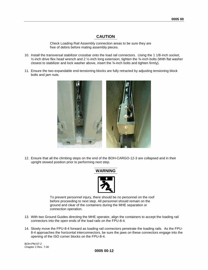
11. Ensure the two expandable end-tensioning blocks are fully retracted by adjusting tensioning block
bolts and jam nuts.
12. Ensure that all the climbing steps on the end of the BOH-CARGO-12-3 are collapsed and in their
upright stowed position prior to performing next step.
WARNING
To prevent personnel injury, there should be no personnel on the roof before proceeding to next step. All personnel should remain on the ground and clear of the containers during the MHE separation or connection operation.
13. With two Ground Guides directing the MHE operator, align the containers to accept the loading rail
connectors into the open ends of the load rails on the FPU-8-4. 14. Slowly move the FPU-8-4 forward as loading rail connectors penetrate the loading rails. As the FPU-
8-4 approaches the horizontal interconnectors, be sure the jaws on these connectors engage into the opening of the ISO corner blocks on the FPU-8-4.
0005 00
BOH-PM-07-2 Chapter 2 Rev. 7.00
0005 00-13
CAUTION
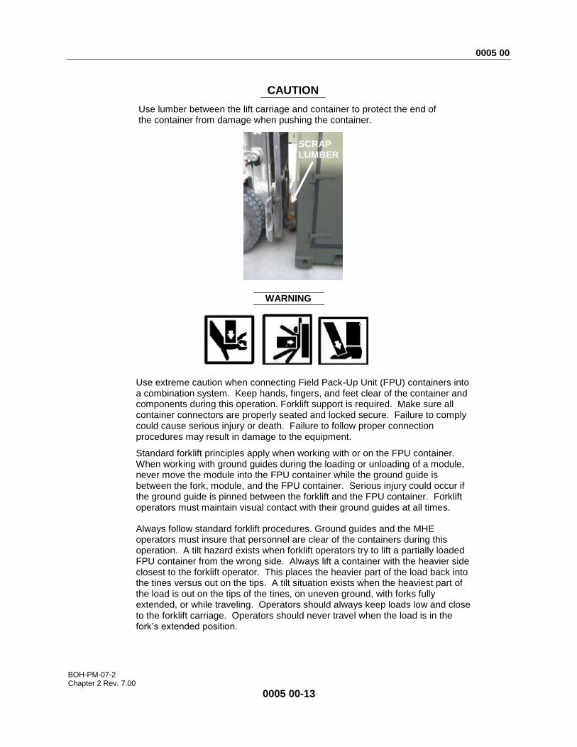
Use lumber between the lift carriage and container to protect the end of the container from damage when pushing the container.
WARNING
Use extreme caution when connecting Field Pack-Up Unit (FPU) containers into a combination system. Keep hands, fingers, and feet clear of the container and components during this operation. Forklift support is required. Make sure all container connectors are properly seated and locked secure. Failure to comply could cause serious injury or death. Failure to follow proper connection procedures may result in damage to the equipment.
Standard forklift principles apply when working with or on the FPU container. When working with ground guides during the loading or unloading of a module, never move the module into the FPU container while the ground guide is between the fork, module, and the FPU container. Serious injury could occur if the ground guide is pinned between the forklift and the FPU container. Forklift operators must maintain visual contact with their ground guides at all times.
Always follow standard forklift procedures. Ground guides and the MHE operators must insure that personnel are clear of the containers during this operation. A tilt hazard exists when forklift operators try to lift a partially loaded FPU container from the wrong side. Always lift a container with the heavier side closest to the forklift operator. This places the heavier part of the load back into the tines versus out on the tips. A tilt situation exists when the heaviest part of the load is out on the tips of the tines, on uneven ground, with forks fully extended, or while traveling. Operators should always keep loads low and close to the forklift carriage. Operators should never travel when the load is in the fork’s extended position.
SCRAP LUMBER
0005 00
BOH-PM-07-2 Chapter 2 Rev. 7.00
0005 00-14
15. Continue moving forward until connectors are firmly seated and the loading rail blocks are under the edge of the FPU-8-4 container.
NOTE Return to the roof only after the two containers have been mated, and the MHE has been disengaged from the container.
16. Return to the roof via the roof access system located on the roller end of the FPU-8-4 to tighten the upper Horizontal interconnectors.
WARNING
Fall hazards exist when climbing onto, returning from or working from the top of the container. Always maintain three points of contact to the ladder and FPU container when climbing onto the FPU container. Never move, step, or walk backwards when working on top of the system. All movement should be in the forward direction. A fall can occur if the worker loses concentration and steps backwards off of the edge. Stand erect only if necessary and only away from the edge. Working from a kneeling position helps reduce the threat of a fall. Do not allow personnel to access the roof via Forklift or other MHE.
17. When the FPU-8-4/BOH-Cargo-12-3 containers are mated and the horizontal interconnectors are
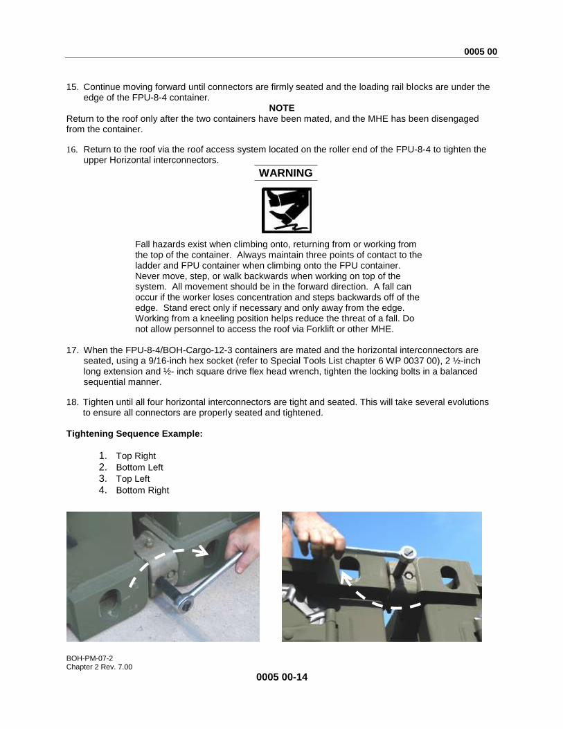
seated, using a 9/16-inch hex socket (refer to Special Tools List chapter 6 WP 0037 00), 2 ½-inch long extension and ½- inch square drive flex head wrench, tighten the locking bolts in a balanced sequential manner.
18. Tighten until all four horizontal interconnectors are tight and seated. This will take several evolutions to ensure all connectors are properly seated and tightened.
Tightening Sequence Example:
1. Top Right
2. Bottom Left
3. Top Left
4. Bottom Right

0005 00
BOH-PM-07-2 Chapter 2 Rev. 7.00
0005 00-15
19. Repeat tightening sequence several times until no more bolt movement is experienced. Ensure that
all four horizontal interconnectors are sufficiently tightened prior to the next steps.
20. The locking adjustment bolts will be recessed and flush with the connector housing when completed.
21. Return to the ground via the roof access system on the end of the FPU-8-4.
22. After all the connector blocks have been tightened, and using the 1 ½-inch open end wrench, adjust the transversal stabilizer tensioning blocks between the containers to a very tight condition.
23. Lock down the jam nut after tightening the stabilizer.
WARNING
Make sure all container connectors are properly seated and secured. Failure to comply could cause serious injury or death.
OPERATION/INSTALLATION OF BRIDGE LOCKS Bridge Locks are connecting devices that utilize the top openings in the ISO corner blocks. These are an enhancement to the connection of the two containers and are designed to be used strictly during ground transportation. Bridge locks should be installed whenever the FPU is to be transported on the HEMTT-LHS, PLS, PLS Trailer, container transport trailer, flatbed trailer, etc. Bridge locks must be removed before turning over to maritime shipping personnel.
CAUTION
Bridge Lock connecters are used in conjunction with horizontal interconnectors for loading and ground transportation and must be removed for maritime shipping to meet container width and height requirements of ISO certification standards.
9/16-INCH HEX HEAD LOCKING ADJUSTMENT BOLTS

0005 00
BOH-PM-07-2 Chapter 2 Rev. 7.00
0005 00-16
The Bridge Lock has one 2 1/8-inch jam nut and one 1-inch flat adjuster nut (refer to Special Tools List chapter 6 WP 0037 00).The nut in the center is the adjuster nut and opens/closes the locks. The other is the jam nut and secures the locks in position after the adjuster nut has been tightened.
WARNING
Fall hazards exist when climbing onto, returning from or working from the top of the container. Always maintain three points of contact to the ladder and FPU container when climbing onto the FPU container. Never move, step, or walk backwards when working on top of the system. All movement should be in the forward direction. A fall can occur if you lose concentration and step backwards off of the edge. Stand erect only if necessary and only away from the edge. Working from a kneeling position helps reduce the threat of a fall.
1. Return to the roof via the roof access system located on the roller end of the FPU-8-4 to tighten the upper horizontal interconnectors.
2. In a kneeling position, orient bridge lock so that jaws turned towards the installer and jam nut is to the installer’s right. Positioning the jam nut to the installer’s right will ensure that the installer is pulling when tightening the adjuster and jam nuts.
WARNING
Always orient the jam nut to the installer’s right to ensure that operator is always pulling towards him in a safe manner. Improper orientation may result in installer falling from the container roof causing serious injury.
ADJUSTER NUT
JAM NUT
JAWS
0005 00
BOH-PM-07-2 Chapter 2 Rev. 7.00
0005 00-17
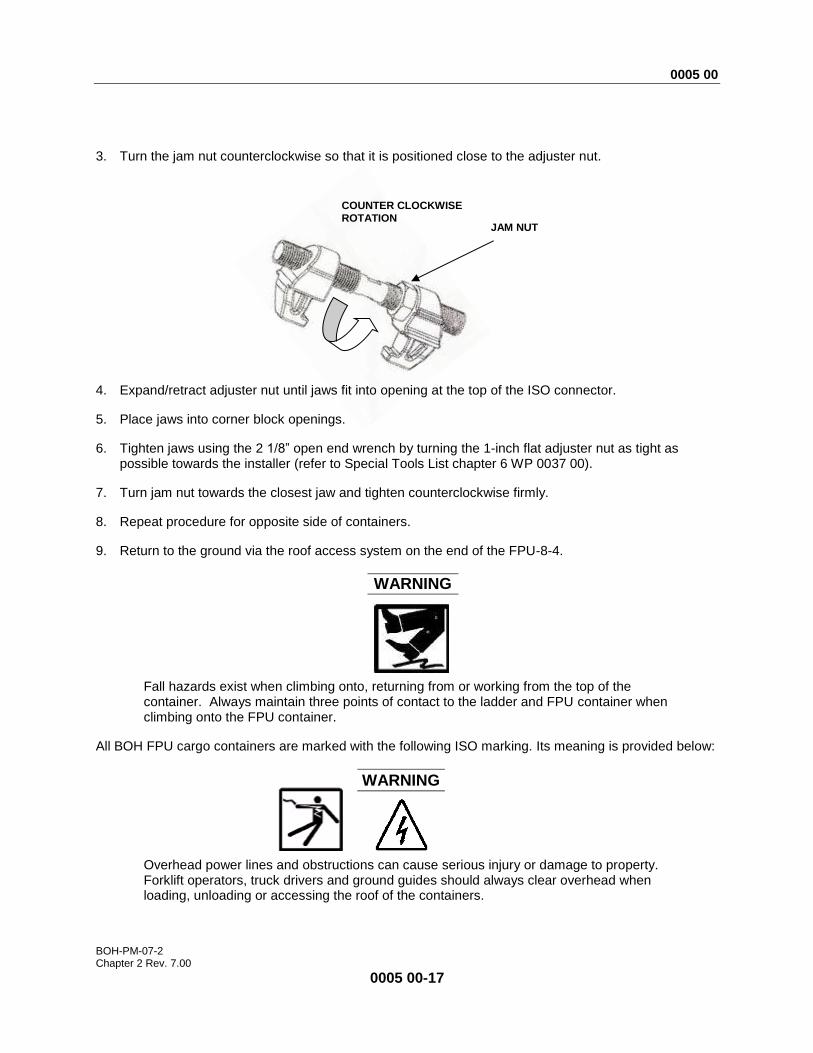
3. Turn the jam nut counterclockwise so that it is positioned close to the adjuster nut.
4. Expand/retract adjuster nut until jaws fit into opening at the top of the ISO connector.
5. Place jaws into corner block openings.
6. Tighten jaws using the 2 1/8” open end wrench by turning the 1-inch flat adjuster nut as tight as possible towards the installer (refer to Special Tools List chapter 6 WP 0037 00).
7. Turn jam nut towards the closest jaw and tighten counterclockwise firmly.
8. Repeat procedure for opposite side of containers.
9. Return to the ground via the roof access system on the end of the FPU-8-4.
WARNING
Fall hazards exist when climbing onto, returning from or working from the top of the container. Always maintain three points of contact to the ladder and FPU container when climbing onto the FPU container.
All BOH FPU cargo containers are marked with the following ISO marking. Its meaning is provided below:
WARNING
Overhead power lines and obstructions can cause serious injury or damage to property. Forklift operators, truck drivers and ground guides should always clear overhead when loading, unloading or accessing the roof of the containers.
COUNTER CLOCKWISE
ROTATION JAM NUT
0005 00
BOH-PM-07-2 Chapter 2 Rev. 7.00
0005 00-18
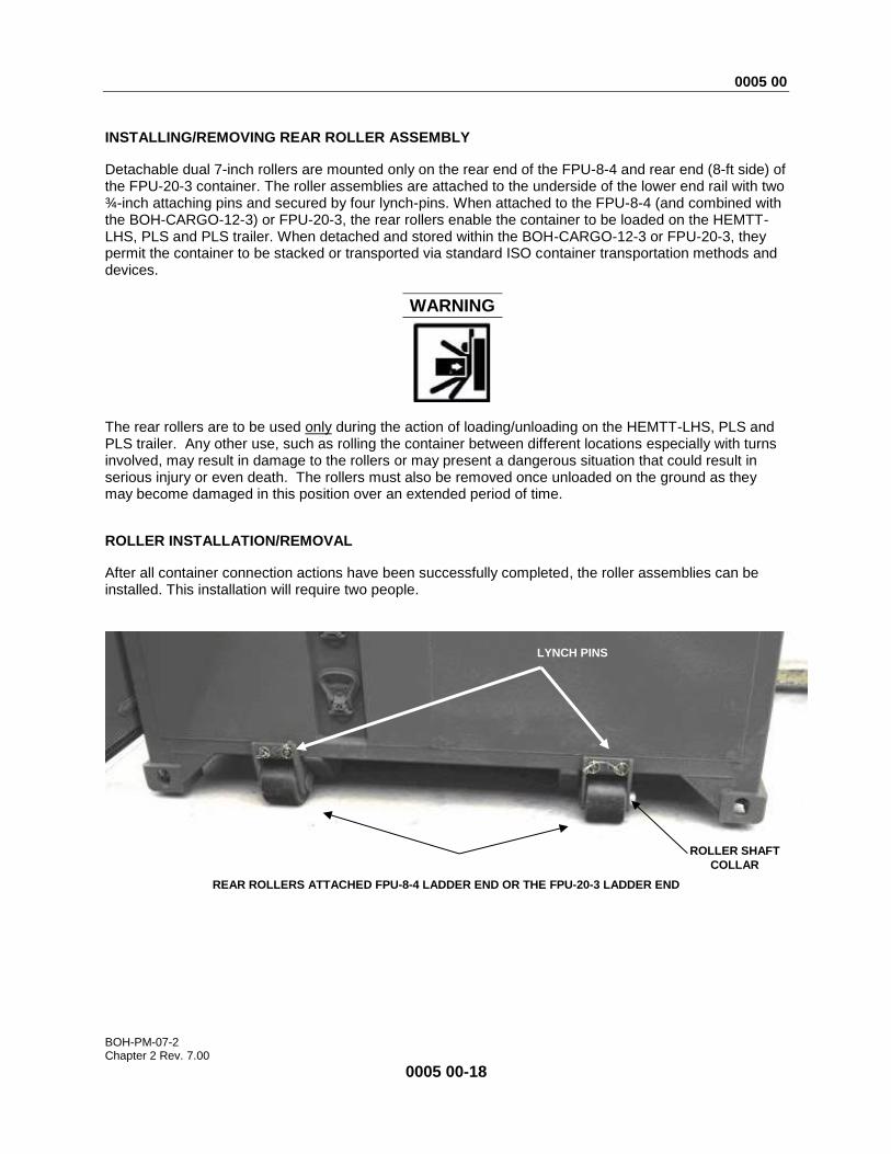
INSTALLING/REMOVING REAR ROLLER ASSEMBLY
Detachable dual 7-inch rollers are mounted only on the rear end of the FPU-8-4 and rear end (8-ft side) of the FPU-20-3 container. The roller assemblies are attached to the underside of the lower end rail with two ¾-inch attaching pins and secured by four lynch-pins. When attached to the FPU-8-4 (and combined with the BOH-CARGO-12-3) or FPU-20-3, the rear rollers enable the container to be loaded on the HEMTT-LHS, PLS and PLS trailer. When detached and stored within the BOH-CARGO-12-3 or FPU-20-3, they permit the container to be stacked or transported via standard ISO container transportation methods and devices.
WARNING
The rear rollers are to be used only during the action of loading/unloading on the HEMTT-LHS, PLS and PLS trailer. Any other use, such as rolling the container between different locations especially with turns involved, may result in damage to the rollers or may present a dangerous situation that could result in serious injury or even death. The rollers must also be removed once unloaded on the ground as they may become damaged in this position over an extended period of time.
ROLLER INSTALLATION/REMOVAL
After all container connection actions have been successfully completed, the roller assemblies can be installed. This installation will require two people.
REAR ROLLERS ATTACHED FPU-8-4 LADDER END OR THE FPU-20-3 LADDER END
LYNCH PINS
ROLLER SHAFT
COLLAR
0005 00
BOH-PM-07-2 Chapter 2 Rev. 7.00
0005 00-19
Installation
1. Using the HEMTT, lift the FPU-8-4/BOH-CARGO-3 or FPU-20-3 container approximately 12-inches off the ground at the FPU roller end to allow access to the rear frame assembly of the container. Leave roller attached for transport and unloading.
WARNING
Do not allow the system to swing if using overhead lift. Always ensure an appropriate sling is used in the lift. Always use properly sized forklift, crane-lifting device. Always use appropriate blocking/bracing in conjunction with proper MHE when working under the container. Failure to comply with these safety measures could cause damage to equipment, serious injury or death.
2. Position roller assembly so that the roller shaft collar faces the nearest side of the container as shown on page 0005 00-18.
3. Person number one fits the roller saddle to the underside of the container frame and aligns the two pinning holes.
4. Second person inserts the two roller attaching pins through the aligned holes to attach roller assembly to container frame.
5. Secure the two roller attaching pins in place using the four lynchpins attached to the exterior side of the roller assembly.
6. Repeat process for the other roller.
Removal 1. While loaded on the HEMTT, remove the 4 linchpins from the exterior side of the roller assemblies.
2. Remove the two pins holding the roller assembly to the container frame.
3. Remove roller assembly from container frame.
4. Lower the FPU-8-4/BOH-CARGO-3, or the FPU-20-3 to the ground with the HEMTT.
WARNING
Ensure all container connectors are properly seated and locked. Additionally, ensure all internal material is secured through the use of drawer locking mechanisms, cargo strap/netting, pallet lock rods, module locking devices (WP 0005 00 - 0006 00). Failure to comply could cause serious injury or death.
0005 00
BOH-PM-07-2 Chapter 2 Rev. 7.00
0005 00-20
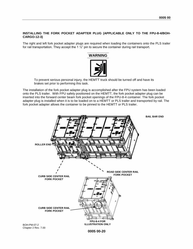
INSTALLING THE FORK POCKET ADAPTER PLUG (APPLICABLE ONLY TO THE FPU-8-4/BOH-CARGO-12-3)
The right and left fork pocket adapter plugs are required when loading the containers onto the PLS trailer for rail transportation. They accept the 1 ½” pin to secure the container during rail transport.
WARNING
To prevent serious personal injury, the HEMTT truck should be turned off and have its brakes set prior to performing this task.
The installation of the fork pocket adapter plug is accomplished after the FPU system has been loaded onto the PLS trailer. With FPU safely positioned on the HEMTT, the fork pocket adapter plug can be inserted into the forward center beam fork pocket openings of the FPU-8-4 container. The fork pocket adapter plug is installed when it is to be loaded on to a HEMTT or PLS trailer and transported by rail. The fork pocket adapter allows the container to be pinned to the HEMTT or PLS trailer.
BAIL BAR END
ROLLER END
ROAD SIDE CENTER RAIL FORK POCKET
CURB SIDE CENTER RAIL FORK POCKET
CURB SIDE CENTER RAIL FORK POCKET
FPU-8-4 FOR ILLUSTRATION ONLY
0005 00
BOH-PM-07-2 Chapter 2 Rev. 7.00
0005 00-21
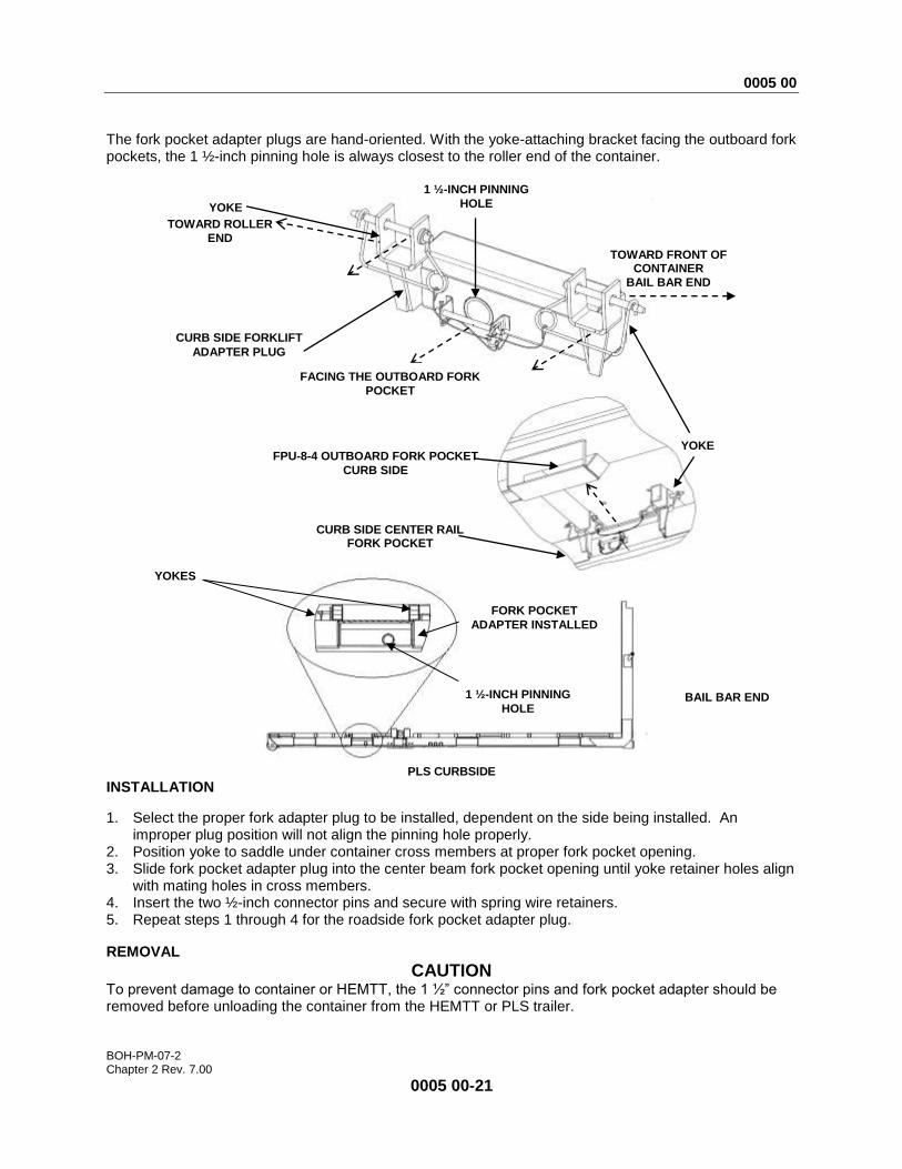
The fork pocket adapter plugs are hand-oriented. With the yoke-attaching bracket facing the outboard fork pockets, the 1 ½-inch pinning hole is always closest to the roller end of the container.
PLS CURBSIDE
INSTALLATION
1. Select the proper fork adapter plug to be installed, dependent on the side being installed. An improper plug position will not align the pinning hole properly.
2. Position yoke to saddle under container cross members at proper fork pocket opening. 3. Slide fork pocket adapter plug into the center beam fork pocket opening until yoke retainer holes align
with mating holes in cross members. 4. Insert the two ½-inch connector pins and secure with spring wire retainers. 5. Repeat steps 1 through 4 for the roadside fork pocket adapter plug.
REMOVAL
CAUTION
To prevent damage to container or HEMTT, the 1 ½” connector pins and fork pocket adapter should be removed before unloading the container from the HEMTT or PLS trailer.
CURB SIDE FORKLIFT
ADAPTER PLUG
YOKE
1 ½-INCH PINNING
HOLE
TOWARD FRONT OF CONTAINER
BAIL BAR END
FACING THE OUTBOARD FORK
BAIL BAR END
FORK POCKET
ADAPTER INSTALLED
YOKES
TOWARD ROLLER
END
CURB SIDE CENTER RAIL FORK POCKET FORK POCKER
FPU-8-4 OUTBOARD FORK POCKET
CURB SIDE
YOKE
1 ½-INCH PINNING
HOLE
0005 00
BOH-PM-07-2 Chapter 2 Rev. 7.00
0005 00-22
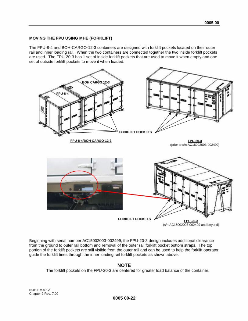
MOVING THE FPU USING MHE (FORKLIFT)
The FPU-8-4 and BOH-CARGO-12-3 containers are designed with forklift pockets located on their outer rail and inner loading rail. When the two containers are connected together the two inside forklift pockets are used. The FPU-20-3 has 1 set of inside forklift pockets that are used to move it when empty and one set of outside forklift pockets to move it when loaded.
Beginning with serial number AC15002003-002499, the FPU-20-3 design includes additional clearance from the ground to outer rail bottom and removal of the outer rail forklift pocket bottom straps. The top portion of the forklift pockets are still visible from the outer rail and can be used to help the forklift operator guide the forklift tines through the inner loading rail forklift pockets as shown above.
NOTE
The forklift pockets on the FPU-20-3 are centered for greater load balance of the container.
FORKLIFT POCKETS
BOH CARGO 12-3
FPU-8-4
FPU-20-3 (prior to s/n AC15002003-002499)
FPU-8-4/BOH-CARGO-12-3
FPU-20-3 (s/n AC15002003-002499 and beyond)
FORKLIFT POCKETS
0005 00
BOH-PM-07-2 Chapter 2 Rev. 7.00
0005 00-23
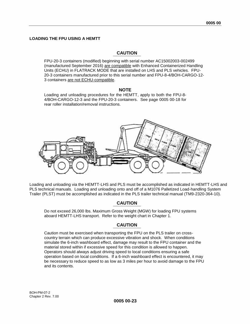
LOADING THE FPU USING A HEMTT
CAUTION
FPU-20-3 containers (modified) beginning with serial number AC15002003-002499 (manufactured September 2016) are compatible with Enhanced Containerized Handling Units (ECHU) in FLATRACK MODE that are installed on LHS and PLS vehicles. FPU-20-3 containers manufactured prior to this serial number and FPU-8-4/BOH-CARGO-12-3 containers are not ECHU-compatible.
NOTE
Loading and unloading procedures for the HEMTT, apply to both the FPU-8-4/BOH-CARGO-12-3 and the FPU-20-3 containers. See page 0005 00-18 for rear roller installation/removal instructions.
Loading and unloading via the HEMTT-LHS and PLS must be accomplished as indicated in HEMTT-LHS and PLS technical manuals. Loading and unloading onto and off of a M1076 Palletized Load-handling System Trailer (PLST) must be accomplished as indicated in the PLS trailer technical manual (TM9-2320-364-10).
CAUTION
Do not exceed 26,000 lbs. Maximum Gross Weight (MGW) for loading FPU systems aboard HEMTT-LHS transport. Refer to the weight chart in Chapter 1.
CAUTION
Caution must be exercised when transporting the FPU on the PLS trailer on cross-country terrain which can produce excessive vibration and shock. When conditions simulate the 6-inch washboard effect, damage may result to the FPU container and the material stored within if excessive speed for this condition is allowed to happen. Operators should always adjust driving speed to local conditions ensuring a safe operation based on local conditions. If a 6-inch washboard effect is encountered, it may be necessary to reduce speed to as low as 3 miles per hour to avoid damage to the FPU and its contents.

0005 00
BOH-PM-07-2 Chapter 2 Rev. 7.00
0005 00-24
SECURING FPU TO THE PLS TRAILER
CAUTION
When transporting the FPU on cross-country terrain which produce excessive vibration and shock. When conditions produce 6-inch washboard effect, damage may result to the FPU container and material stored within if excessive speed is allowed. Operators should adjust driving speed to local conditions. If a 6-inch washboard condition is encountered, operators should reduce speed to as low as 3 mile per hour to avoid damage to the FPU and its contents.
Refer to the PLS trailer TM to determine when the PLS is to be used. FPU forklift pocket adapter plugs and rear rollers are required to be installed for the following operation.
1. After loading the FPU on to the trailer, pinning holes must align with mating holes in trailer frame. If these do not align, recheck orientation of rear roller assembly, orientation of fork pocket adapter plugs and ensure rollers on rear roller assemblies are contacting the roller stops on the PLS trailer. Correct as necessary. See page 0005 00-18 for rear roller installation/removal instructions.
2. Remove the 1 ½-inch diameter PLS trailer load securing pins and insert into fork pocket adapter plug pinning holes.
3. Secure PLS load securing pins in place by inserting the 3/8-inch by 4-inch long hitch pins through pin retainer brackets.
4. Secure hitch pins by inserting hairpin into hitch pin safety hole.
END OF WORK PACKAGE

0006 00
BOH-PM-07-2 Chapter 2 Rev. 7.00
0006 00-1
OPERATOR INSTRUCTIONS
FPU® SYSTEMS OPERATION MANUAL (INCLUDING REPAIR PARTS & SPECIAL TOOL LIST)
MODELS FPU-8-4/BOH-CARGO-12-3 & FPU-20-3 BOH FPU Field Pack-up Units
OPERATION OF FPU CONTAINERS
OPERATION OF FPU CONTAINERS This work package provides procedures associated with safe and efficient operation of the FPU and FPU components. Familiarity with these procedures will allow military units to derive maximum benefit from FPU modularity and the options for FPU configuration.
FPU-8-4 CONNECTED TO BOH-CARGO-12-3
F E
D C
B
A A B
C D
E F
BAIL BAR BAIL BAR
CURB SIDE
BAIL BAR BAIL BAR
CURB SIDE STREET SIDE
STREET SIDE
FPU 20-3
F
E
D C
B A
A B
C
D E
F
0006 00
BOH-PM-07-2 Chapter 2 Rev. 7.00
0006 00-2
OPERATION OF FPU DOORS
Opening the Doors
The FPU-20-3 doors are in the same configuration as the combined FPU 8-4 and BOH-CARGO-12-3. All of the following Warnings, Cautions and procedural steps apply to the FPU-20-3 when opening, closing and securing the doors.
NOTE Doors on the FPU-8-4 should be opened simultaneously. When opening the BOH-CARGO-12-3, open the left and right center doors D and E simultaneously, then open both left and right doors C and F.
WARNING
Use care when opening door while containers are on an incline, to maintain control consider the ground surface conditions for adequate traction, such as mud, snow, ice, sand and seek assistance from fellow soldiers to prevent strain or injury.
CAUTION
When closing the BOH-CARGO-12-3 and FPU 20-3 center doors or the FPU-8-4 doors, always allow the right hand door to lead slightly to mate the door seal edges and prevent damage to the seals.
CAUTION
The FPU containers will exceed the width requirement if a heavy security padlock is used to secure the exterior doors. Padlocks not exceeding one-inch shank length will allow the width requirements to be met. Padlocks may be taped to the exterior doors to ensure further measures will stay within the ISO envelope.
FPU-8-4 and FPU 20-3 Container Doors
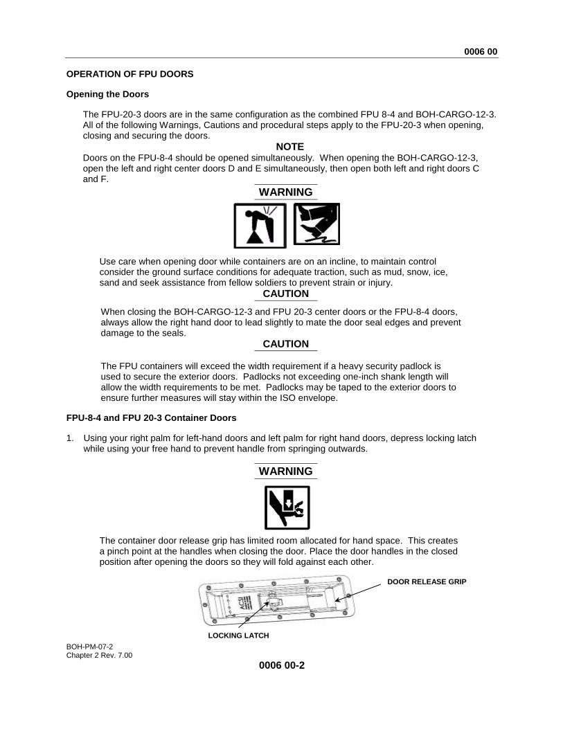
1. Using your right palm for left-hand doors and left palm for right hand doors, depress locking latch while using your free hand to prevent handle from springing outwards.
WARNING
The container door release grip has limited room allocated for hand space. This creates a pinch point at the handles when closing the door. Place the door handles in the closed position after opening the doors so they will fold against each other.
DOOR RELEASE GRIP
LOCKING LATCH
0006 00
BOH-PM-07-2 Chapter 2 Rev. 7.00
0006 00-3
2. Rotate both handles to their fully open position. 3. Pull both handles simultaneously. Because containers are constructed with tubular steel and are
subject to flexing when containers are sitting on an un-level surface, doors may be difficult to open. In this event, you may require the assistance of other personnel to open the doors.
CAUTION
After doors are open, door handles must be re-latched in their closed position to prevent equipment damage to handles as doors are folded back in the open position.
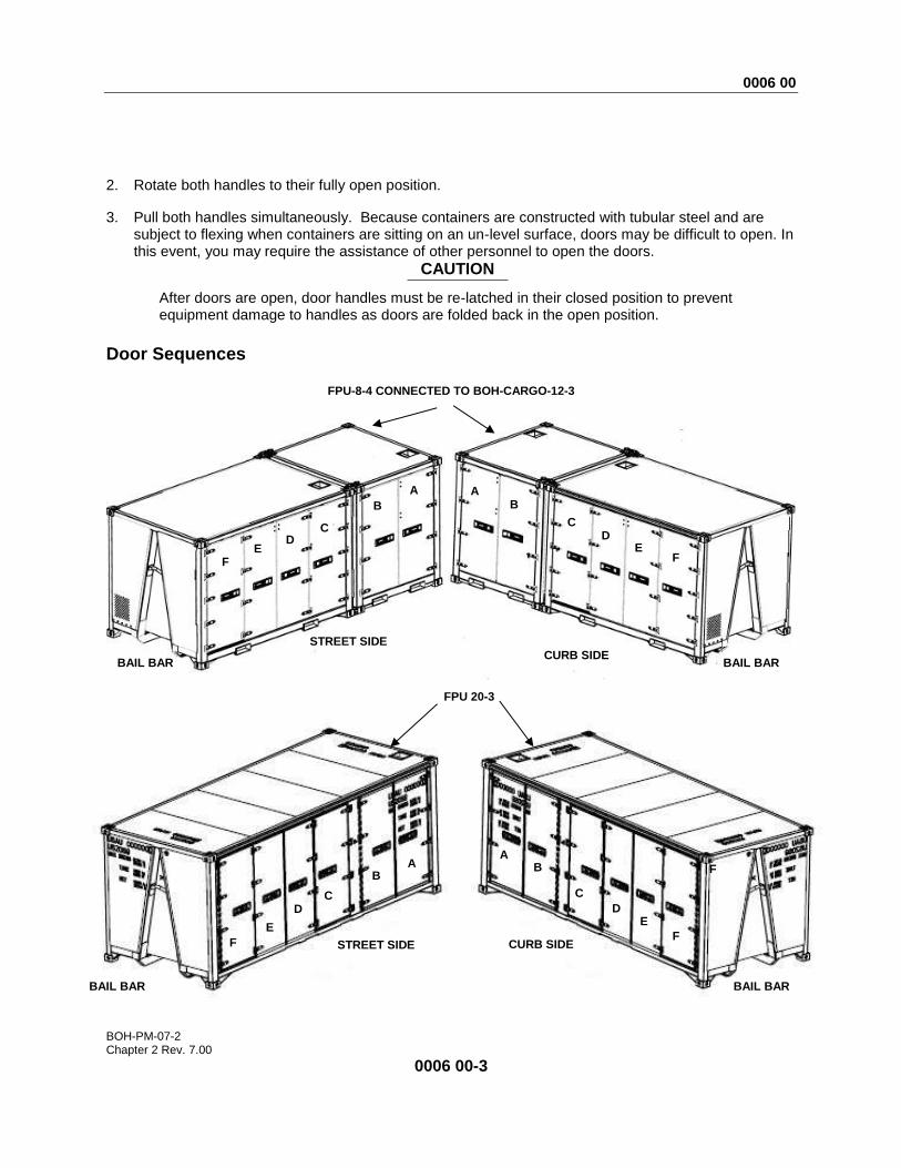
Door Sequences
FPU-8-4 CONNECTED TO BOH-CARGO-12-3
F E
D C
B
A A B
C D
E F
BAIL BAR BAIL BAR
CURB SIDE
BAIL BAR BAIL BAR
CURB SIDE STREET SIDE
STREET SIDE
FPU 20-3
F
F
E
D C
B A
A B
C
D E
F

0006 00
BOH-PM-07-2 Chapter 2 Rev. 7.00
0006 00-4
WARNING
To prevent injury to personnel, after opening each door, install door restraints to prevent accidental closing due to wind conditions or when the container is resting on an un-level surface. Assistance may be required for this operation.
Door Restraint straps for FPU 8-4/BOH CARGO 12-3
The FPU-8-4 and BOH CARGO 12-3 container doors are retained by fabric straps with shackles to welded rings on the end and interior of the door. Secure the doors using door restraint straps.
DOOR RESTRAINTS
FPU 8-4 BOH-CARGO-12-3

0006 00
BOH-PM-07-2 Chapter 2 Rev. 7.00
0006 00-5
Separated FPU 8-4 and BOH CARGO 12-3 When the FPU-8-4 and BOH-CARGO-12-3 containers are separated, they each have additional rings that are welded on the end of each container to accept the strap shackles. (Not applicable to the FPU-20-3).
1. Rotate the handles to their full open position.
CAUTION
When doors are completely open, return the handles to the latched in closed position to prevent equipment damage to handles as doors are folded back in the open position.
2. With assistance, grasp both the center door handles and pull bi-fold doors simultaneously. Because containers are constructed with tubular steel and are subject to flexing when containers are sitting on an un-level surface, doors may be difficult to open. In this event you may require the assistance of other personnel to open the doors. While pulling on center doors simultaneously, have additional personnel pull handles on doors.
3. Fold the doors and retract away from the container. Attach the restraining straps.
FPU 8-4
BOH-CARGO-12-3
0006 00
BOH-PM-07-2 Chapter 2 Rev. 7.00
0006 00-6
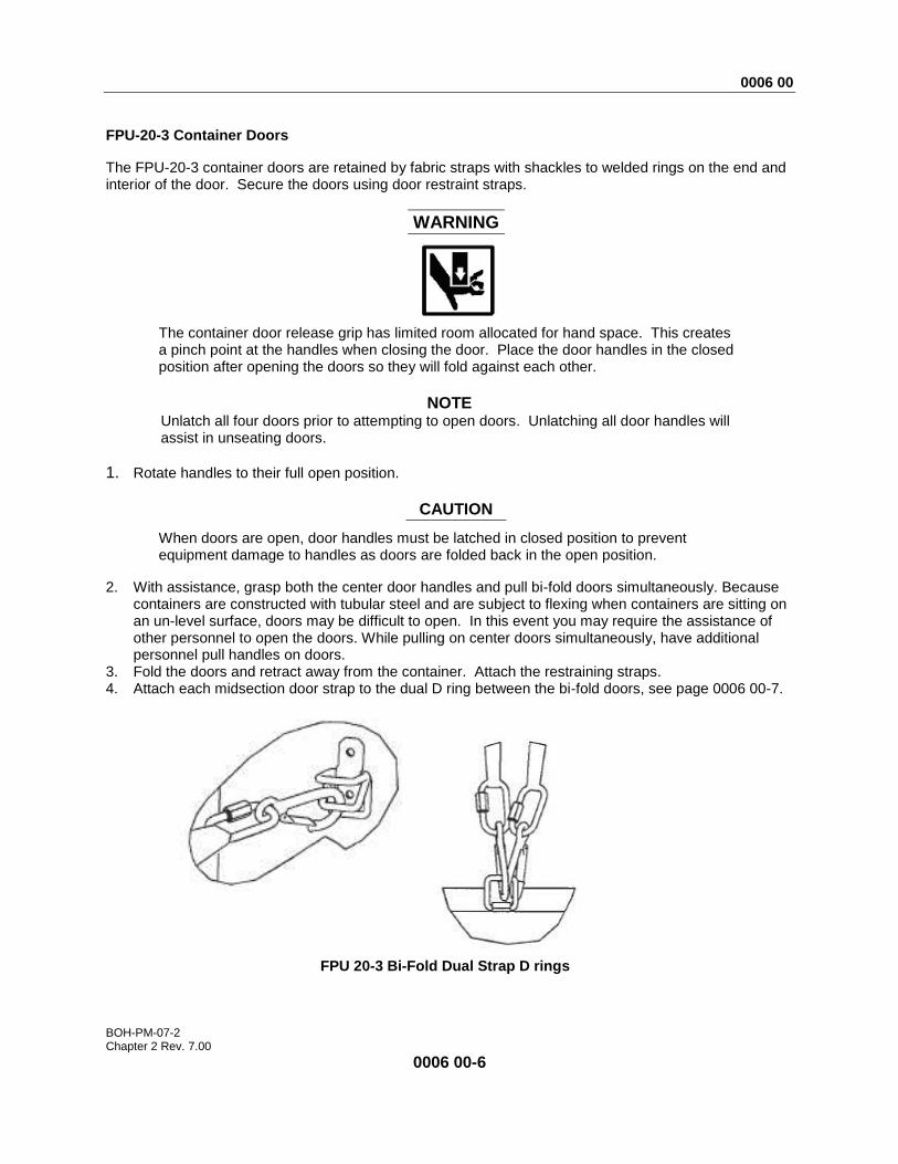
FPU-20-3 Container Doors
The FPU-20-3 container doors are retained by fabric straps with shackles to welded rings on the end and interior of the door. Secure the doors using door restraint straps.
WARNING
The container door release grip has limited room allocated for hand space. This creates a pinch point at the handles when closing the door. Place the door handles in the closed position after opening the doors so they will fold against each other.
NOTE
Unlatch all four doors prior to attempting to open doors. Unlatching all door handles will assist in unseating doors.
1. Rotate handles to their full open position.
CAUTION
When doors are open, door handles must be latched in closed position to prevent equipment damage to handles as doors are folded back in the open position.
2. With assistance, grasp both the center door handles and pull bi-fold doors simultaneously. Because containers are constructed with tubular steel and are subject to flexing when containers are sitting on an un-level surface, doors may be difficult to open. In this event you may require the assistance of other personnel to open the doors. While pulling on center doors simultaneously, have additional personnel pull handles on doors.
3. Fold the doors and retract away from the container. Attach the restraining straps. 4. Attach each midsection door strap to the dual D ring between the bi-fold doors, see page 0006 00-7.
FPU 20-3 Bi-Fold Dual Strap D rings
0006 00
BOH-PM-07-2 Chapter 2 Rev. 7.00
0006 00-7
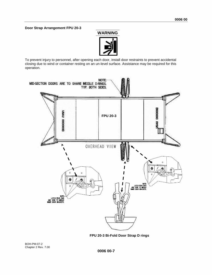
Door Strap Arrangement FPU 20-3
WARNING
To prevent injury to personnel, after opening each door, install door restraints to prevent accidental closing due to wind or container resting on an un-level surface. Assistance may be required for this operation.
FPU 20-3 Bi-Fold Door Strap D rings
FPU 20-3
0006 00
BOH-PM-07-2 Chapter 2 Rev. 7.00
0006 00-8
Closing the Doors
FPU door seals consist of a double lip design in which the inner lip forms a tight seal against a fixed surface around the door opening while the outer seal overlaps the door facing to provide a double sealing protection against the environment. Overlapping doors require one door (left side) to have double seal lips while the adjacent door (right side) has a single seal lip (no outer seal lip). During the closing process, as the overlapping doors begin to mate, be sure that the door with no outer seal lip (right side) is ahead of the double seal lip door (left side).
WARNING
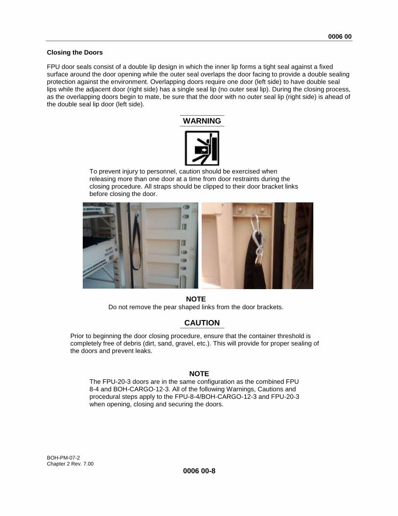
To prevent injury to personnel, caution should be exercised when releasing more than one door at a time from door restraints during the closing procedure. All straps should be clipped to their door bracket links before closing the door.
NOTE Do not remove the pear shaped links from the door brackets.
CAUTION
Prior to beginning the door closing procedure, ensure that the container threshold is completely free of debris (dirt, sand, gravel, etc.). This will provide for proper sealing of the doors and prevent leaks.
NOTE The FPU-20-3 doors are in the same configuration as the combined FPU 8-4 and BOH-CARGO-12-3. All of the following Warnings, Cautions and procedural steps apply to the FPU-8-4/BOH-CARGO-12-3 and FPU-20-3 when opening, closing and securing the doors.
0006 00
BOH-PM-07-2 Chapter 2 Rev. 7.00
0006 00-9
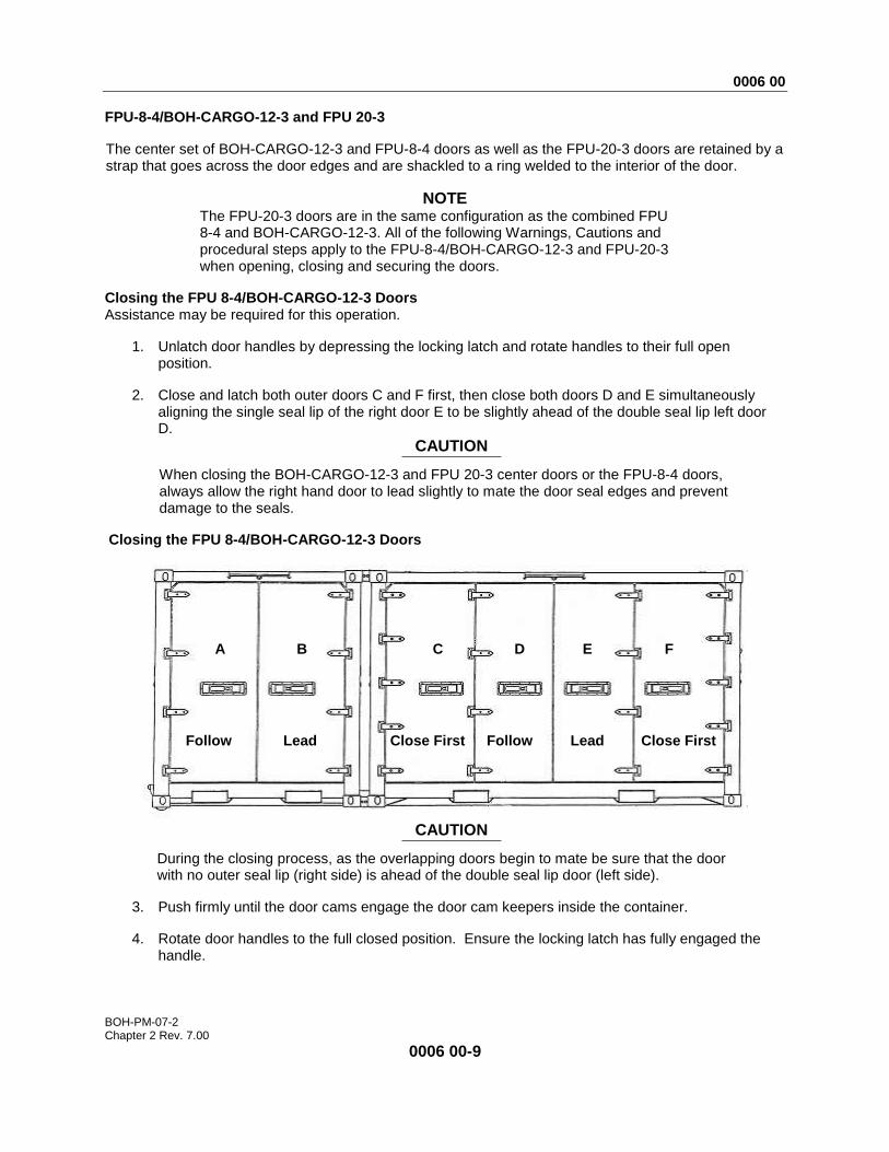
FPU-8-4/BOH-CARGO-12-3 and FPU 20-3
The center set of BOH-CARGO-12-3 and FPU-8-4 doors as well as the FPU-20-3 doors are retained by a strap that goes across the door edges and are shackled to a ring welded to the interior of the door.
NOTE The FPU-20-3 doors are in the same configuration as the combined FPU 8-4 and BOH-CARGO-12-3. All of the following Warnings, Cautions and procedural steps apply to the FPU-8-4/BOH-CARGO-12-3 and FPU-20-3 when opening, closing and securing the doors.
Closing the FPU 8-4/BOH-CARGO-12-3 Doors Assistance may be required for this operation.
1. Unlatch door handles by depressing the locking latch and rotate handles to their full open position.
2. Close and latch both outer doors C and F first, then close both doors D and E simultaneously aligning the single seal lip of the right door E to be slightly ahead of the double seal lip left door D.
CAUTION
When closing the BOH-CARGO-12-3 and FPU 20-3 center doors or the FPU-8-4 doors, always allow the right hand door to lead slightly to mate the door seal edges and prevent damage to the seals.
Closing the FPU 8-4/BOH-CARGO-12-3 Doors
CAUTION
During the closing process, as the overlapping doors begin to mate be sure that the door with no outer seal lip (right side) is ahead of the double seal lip door (left side).
3. Push firmly until the door cams engage the door cam keepers inside the container.
4. Rotate door handles to the full closed position. Ensure the locking latch has fully engaged the handle.
A B C D E F
Close First Close First Follow Follow Lead Lead
0006 00
BOH-PM-07-2 Chapter 2 Rev. 7.00
0006 00-10
NOTE If the top or bottom of the door does not seat inside the doorframe, the doors have not made proper contact with the door cam keeper.
CAUTION
When doors are open, door handles must be latched in closed position to prevent equipment damage to handles as doors are folded back in the open position.
Closing the FPU-20-3 Doors Assistance may be required for this operation.
1. Close and latch both outer doors C and F first, then close both doors D and E simultaneously aligning the single seal lip of the right door E to be slightly ahead of the double seal lip left door D.
CAUTION
During the closing process, as the overlapping doors begin to mate be sure that the door with no outer seal lip (right side) is ahead of the double seal lip door (left side).
2. Push firmly until the door cams engage the door cam keepers inside the container.
3. Rotate door handles to the full closed position. Ensure the locking latch has fully engaged the handle.
CAUTION The FPU containers will exceed the width requirement if a heavy security padlock is used to secure the exterior doors. Padlocks not exceeding one-inch shank length will allow the width requirements to be met. Padlocks may be taped to the exterior doors to ensure further measures will stay within the ISO envelope.
Follow (A)
Follow (D)
Lead (B)
Lead (E)
Close First (F)
Close First (C) A
B
C
D
E F
0006 00
BOH-PM-07-2 Chapter 2 Rev. 7.00
0006 00-11
OPERATING ADJUSTABLE DRAWERS WHEN CONFIGURED WITH PARTS STORAGE AIDS (BOH-CARGO-12-3 and front section of the FPU-20-3)
NOTE The FPU-20-3 adjustable drawers are in the same configuration as the BOH-CARGO-12-3. All of the following Warnings, Cautions and procedural steps apply to the FPU-20-3 when removing, installing, adjusting and securing the drawers
Adjustable drawer slide ledges have been installed in the BOH-CARGO-12-3 and FPU-20-3 parts container. These slide ledge assemblies are attached to the vertical rack frame at two locations by four ¼ inch carriage bolts at each point of attachment. Drawers are mounted to these ledges by four bolts on each ledge.
All drawers are full extension and are operationally secured by locking rod handles to prevent opening during transport or accidental closing during use. Drawers consist of fixed longitudinal dividers and moveable transversal dividers that allow adjustment on two-inch centers. Drawers are rated with a maximum load weight limit of 150 lbs. per drawer.
CAUTION
Do not exceed maximum weight limit of 150lbs per drawer. Exceeding load limits may damage slide and drawer systems.
Opening and Closing Drawers (FPU parts only)
WARNING
Use care when opening drawers while containers are on an incline. Physical injury may occur. The container should be placed on as level a terrain as possible and periodically be checked for shift in its position from its level state.
Do not use bottom drawers or pallets as step substitutes when trying to access material located in upper drawers and on pallets. It is recommended that an optional 4-step stairway with handrail be used to access upper drawer and pallet material.
CAUTION
Never allow material to exceed the height of the drawer sides. Material exceeding drawer height will interfere with travel of that drawer and the drawer above.
0006 00
BOH-PM-07-2 Chapter 2 Rev. 7.00
0006 00-12
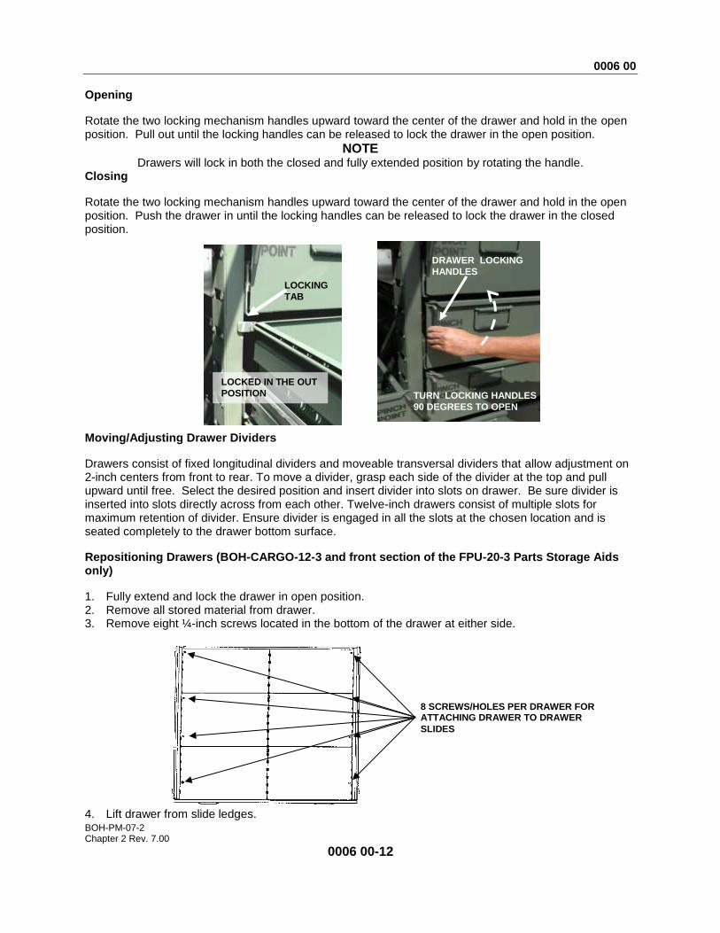
Opening
Rotate the two locking mechanism handles upward toward the center of the drawer and hold in the open position. Pull out until the locking handles can be released to lock the drawer in the open position.
NOTE
Drawers will lock in both the closed and fully extended position by rotating the handle. Closing
Rotate the two locking mechanism handles upward toward the center of the drawer and hold in the open position. Push the drawer in until the locking handles can be released to lock the drawer in the closed position.
Moving/Adjusting Drawer Dividers
Drawers consist of fixed longitudinal dividers and moveable transversal dividers that allow adjustment on 2-inch centers from front to rear. To move a divider, grasp each side of the divider at the top and pull upward until free. Select the desired position and insert divider into slots on drawer. Be sure divider is inserted into slots directly across from each other. Twelve-inch drawers consist of multiple slots for maximum retention of divider. Ensure divider is engaged in all the slots at the chosen location and is seated completely to the drawer bottom surface.
Repositioning Drawers (BOH-CARGO-12-3 and front section of the FPU-20-3 Parts Storage Aids only)
1. Fully extend and lock the drawer in open position. 2. Remove all stored material from drawer. 3. Remove eight ¼-inch screws located in the bottom of the drawer at either side.
4. Lift drawer from slide ledges.
LOCKING
TAB
DRAWER LOCKING
HANDLES
TURN LOCKING HANDLES
90 DEGREES TO OPEN
LOCKED IN THE OUT
POSITION
8 SCREWS/HOLES PER DRAWER FOR ATTACHING DRAWER TO DRAWER
SLIDES

0006 00
BOH-PM-07-2 Chapter 2 Rev. 7.00
0006 00-13
CAUTION
If a bolt is lost or damaged beyond use, obtain a replacement. Do not install with less than the proper number of bolts, or equipment damage may occur.
5. Loosen, but do not remove, the four front and rear 7/16-inch nuts on the carriage bolts using a 7/16-
inch socket with ratchet and extension.
6. Slide ledges are retained on the vertical rack frame by two bayonet tabs; protruding into the windows of the vertical rack frame. This requires the ledge to be loosened from the vertical rack frame. While one person securely holds the slide ledge, the second person applies an upward force by tapping the underside of the ledge at the attached point with a 2 X 4 soft wooden block or similar material.
7. Place the drawer slides ledges in their desired positions by inserting the bayonet tabs into the vertical rack frame windows. Then align the four carriage bolts into their appropriate slots.
8. Tap down on the ledge a 2 X 4 soft wooden block or similar material. 9. Ensure the carriage bolts drop completely down in the slots.
NOTE Drawers may be adjusted in 4-inch increments.
10. Tighten drawer slide ledge to rack frame by tightening the four ¼ -inch carriage bolts and nuts using a
¼ -inch socket with ratchet and extension. 11. Reposition the drawer on to the slide ledge careful to align mounting holes. 12. Install all eight bolts and lightly hand-tighten. 13. After hand tightening the eight ¼-inch mounting screws, push drawer completely closed and pull back
to its fully-extended position to allow the drawer to seat into its proper location on the drawer slide ledge.
CAUTION
Be careful not to over tighten when securing the eight ¼-inch mounting screws.
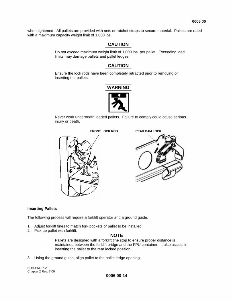
OPERATING FPU PALLETS (BULK STORAGE AIDS) Each pallet position in the pallet rack system consists of a pallet and left and right load centering adjustable pallet mounting ledges. Ledge assemblies are attached to the vertical rack frame at two locations by ten ¼ -inch carriage bolts and nuts. When pallet is inserted on pallet ledges, they are secured by rear cam locks and held in front by two adjustable lock rods that seat the pallet into position
CARRIAGE BOLT LOCATIONS
DRAWER SLIDE LEDGE ASSEMBLY
FRAME WINDOW
0006 00
BOH-PM-07-2 Chapter 2 Rev. 7.00
0006 00-14
when tightened. All pallets are provided with nets or ratchet straps to secure material. Pallets are rated with a maximum capacity weight limit of 1,000 lbs.
CAUTION
Do not exceed maximum weight limit of 1,000 lbs. per pallet. Exceeding load limits may damage pallets and pallet ledges.
CAUTION
Ensure the lock rods have been completely retracted prior to removing or inserting the pallets.
WARNING
Never work underneath loaded pallets. Failure to comply could cause serious injury or death.
Inserting Pallets The following process will require a forklift operator and a ground guide. 1. Adjust forklift tines to match fork pockets of pallet to be installed. 2. Pick up pallet with forklift.
NOTE Pallets are designed with a forklift tine stop to ensure proper distance is maintained between the forklift bridge and the FPU container. It also assists in inserting the pallet to the rear locked position.
3. Using the ground guide, align pallet to the pallet ledge opening.
FRONT LOCK ROD REAR CAM LOCK

0006 00
BOH-PM-07-2 Chapter 2 Rev. 7.00
0006 00-15
CAUTION
Ensure the lock rods have been completely retracted prior to removing or inserting the pallets.
4. Once approximately 12-inches into the pallet ledge, lower the pallet and allow it to slide along the
pallet ledge into the lock position. 5. Retract forklift. 6. Tighten the lock rods evenly to 120 lb.-in. (105 psi) using 7/8-inch deep well socket and 1/2-inch
drive flex head wrench to secure the front of the pallets. Continue alternating from one lock rod to the other until the pallet is properly seated under the locking cam located at the rear of the pallet.
NOTE Alternate tightening sequence left to right to ensure proper alignment of pallet on pallet ledges.
7. Tighten Jam nut using 7/8-inch combination wrench to hold lock rod in the closed position. Removing Pallets 1. Loosen jam nuts using 7/8-inch combination wrench.
NOTE All hardware, bolts, jam nuts, and screws are loosened with a counter clockwise rotation. All hardware, bolts, jam nuts, and screws are tightened with a clockwise rotation.
COUNTERCLOCKWISE
CLOCKWISE
0006 00
BOH-PM-07-2 Chapter 2 Rev. 7.00
0006 00-16
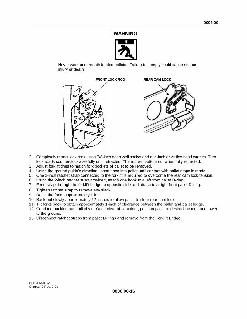
WARNING
Never work underneath loaded pallets. Failure to comply could cause serious injury or death.
2. Completely retract lock rods using 7/8-inch deep well socket and a ½-inch drive flex head wrench. Turn
lock roads counterclockwise fully until retracted. The rod will bottom out when fully retracted. 3. Adjust forklift tines to match fork pockets of pallet to be removed. 4. Using the ground guide’s direction, insert tines into pallet until contact with pallet stops is made. 5. One 2-inch ratchet strap connected to the forklift is required to overcome the rear cam lock tension. 6. Using the 2-inch ratchet strap provided, attach one hook to a left front pallet D-ring. 7. Feed strap through the forklift bridge to opposite side and attach to a right front pallet D-ring.
8. Tighten ratchet strap to remove any slack. 9. Raise the forks approximately 1-inch. 10. Back out slowly approximately 12-inches to allow pallet to clear rear cam lock. 11. Tilt forks back to obtain approximately 1-inch of clearance between the pallet and pallet ledge. 12. Continue backing out until clear. Once clear of container, position pallet to desired location and lower
to the ground. 13. Disconnect ratchet straps from pallet D-rings and remove from the Forklift Bridge.
FRONT LOCK ROD REAR CAM LOCK

0006 00
BOH-PM-07-2 Chapter 2 Rev. 7.00
0006 00-17
Adjusting Pallet Position 1. Remove the pallet to be relocated and any pallets located above prior to beginning the following steps
(Refer to inserting/removing pallet procedures). 2. Remove front and rear pallet ledge stabilizer by turning attaching bolts counterclockwise on each side
of the stabilizer using 3/16-inch hex driver socket and 3/8-inch ratchet with an extension.
NOTE The operator must crawl into the container to remove the rear Allen bolts.
3. Loosen, but do not remove, the ten carriage bolt nuts using 7/16-inch socket and ratchet with
extension from the two pallet ledges on the vertical rack frame.
CAUTION
If a bolt is lost or damaged beyond use, obtain a replacement. Do not install with less than the proper number of bolts or damage to equipment may occur.
4. Pallet ledges are retained on the vertical rack frame by ten ¼-inch carriage bolts and four bayonet tabs protruding into the windows of the vertical rack frame. This requires the ledge to be loosened from the vertical rack frame. While one person securely holds the pallet ledge, the second person applies an upward force by tapping the underside of the ledge at the attached point with a 2 X 4 soft wooden block or similar material.
PALLET STABILIZER ATTACHING BOLTS
TAB
ADJSTMENT BOLT
REAR CAM
LOCK LOCK ROD
PALLET LEDGE
JAM NUT
0006 00
BOH-PM-07-2 Chapter 2 Rev. 7.00
0006 00-18
5. Place the pallet ledges in their desired positions by inserting the bayonet tabs into the vertical rack frame windows while aligning the ten carriage bolts into their appropriate slots. Ensure that pallet ledges are at the same height in the vertical rack frame. Ensure all bayonet tabs have engaged the vertical rack frame windows before tapping into place. Tap down on the ledge with a 2 X 4 soft wooden block or similar material. Ensure the carriage bolts drop completely down in the slots.
NOTE Pallets may be adjusted in 4-inch increments
6. Tighten all ¼-inch carriage bolts using a 7/16” socket wrench, ratchet and extension.
7. Reinstall rear pallet ledge stabilizer, four button head bolts using 3/16-inch hex driver socket and 3/8-inch ratchet with extension from the two positions of each pallet ledge. There are four bolts located at each vertical rack frame.
8. Reinstall front pallet ledge stabilizer, four button head bolts using 3/16-inch hex driver socket and 3/8-inch ratchet with extension from the two positions of each pallet ledge. There are four bolts located at each vertical rack frame.
9. Reinstall pallet (see Inserting Pallets page 0006 00-14).
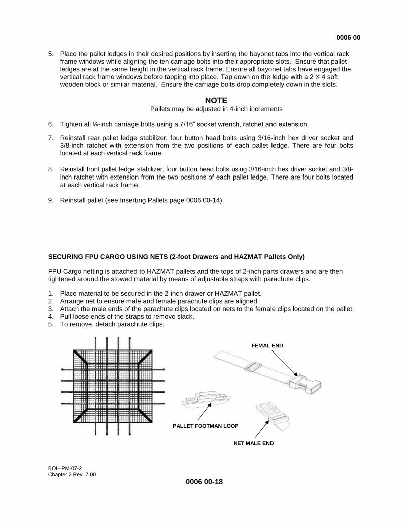
SECURING FPU CARGO USING NETS (2-foot Drawers and HAZMAT Pallets Only)
FPU Cargo netting is attached to HAZMAT pallets and the tops of 2-inch parts drawers and are then tightened around the stowed material by means of adjustable straps with parachute clips.
1. Place material to be secured in the 2-inch drawer or HAZMAT pallet. 2. Arrange net to ensure male and female parachute clips are aligned. 3. Attach the male ends of the parachute clips located on nets to the female clips located on the pallet. 4. Pull loose ends of the straps to remove slack. 5. To remove, detach parachute clips.
PALLET FOOTMAN LOOP
NET MALE END
FEMAL END
0006 00
BOH-PM-07-2 Chapter 2 Rev. 7.00
0006 00-19
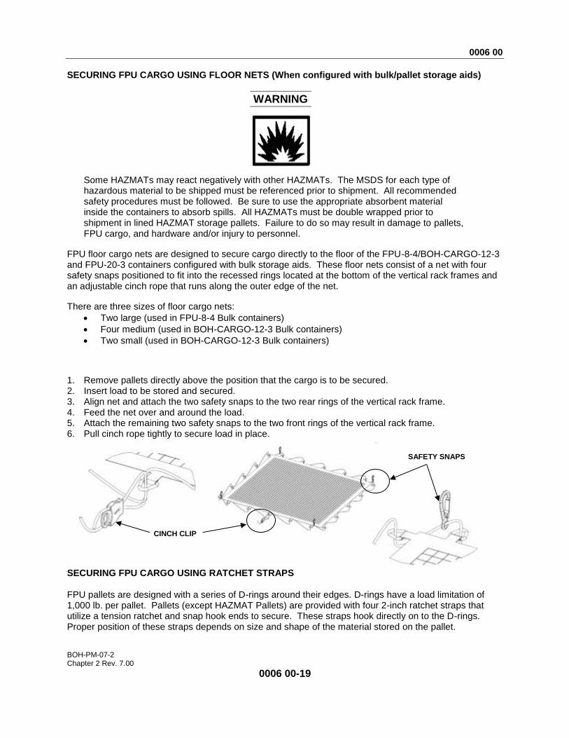
SECURING FPU CARGO USING FLOOR NETS (When configured with bulk/pallet storage aids)
WARNING
Some HAZMATs may react negatively with other HAZMATs. The MSDS for each type of hazardous material to be shipped must be referenced prior to shipment. All recommended safety procedures must be followed. Be sure to use the appropriate absorbent material inside the containers to absorb spills. All HAZMATs must be double wrapped prior to shipment in lined HAZMAT storage pallets. Failure to do so may result in damage to pallets, FPU cargo, and hardware and/or injury to personnel.
FPU floor cargo nets are designed to secure cargo directly to the floor of the FPU-8-4/BOH-CARGO-12-3 and FPU-20-3 containers configured with bulk storage aids. These floor nets consist of a net with four safety snaps positioned to fit into the recessed rings located at the bottom of the vertical rack frames and an adjustable cinch rope that runs along the outer edge of the net.
There are three sizes of floor cargo nets:
Two large (used in FPU-8-4 Bulk containers)
Four medium (used in BOH-CARGO-12-3 Bulk containers)
Two small (used in BOH-CARGO-12-3 Bulk containers)
1. Remove pallets directly above the position that the cargo is to be secured. 2. Insert load to be stored and secured. 3. Align net and attach the two safety snaps to the two rear rings of the vertical rack frame. 4. Feed the net over and around the load. 5. Attach the remaining two safety snaps to the two front rings of the vertical rack frame. 6. Pull cinch rope tightly to secure load in place.
SECURING FPU CARGO USING RATCHET STRAPS FPU pallets are designed with a series of D-rings around their edges. D-rings have a load limitation of 1,000 lb. per pallet. Pallets (except HAZMAT Pallets) are provided with four 2-inch ratchet straps that utilize a tension ratchet and snap hook ends to secure. These straps hook directly on to the D-rings. Proper position of these straps depends on size and shape of the material stored on the pallet.
SAFETY SNAPS
CINCH CLIP
0006 00
BOH-PM-07-2 Chapter 2 Rev. 7.00
0006 00-20
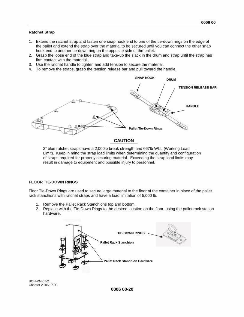
Ratchet Strap 1. Extend the ratchet strap and fasten one snap hook end to one of the tie-down rings on the edge of
the pallet and extend the strap over the material to be secured until you can connect the other snap hook end to another tie-down ring on the opposite side of the pallet.
2. Grasp the loose end of the blue strap and take-up the slack in the drum and strap until the strap has firm contact with the material.
3. Use the ratchet handle to tighten and add tension to secure the material. 4. To remove the straps, grasp the tension release bar and pull toward the handle.
CAUTION
2” blue ratchet straps have a 2,000lb break strength and 667lb WLL (Working Load Limit). Keep in mind the strap load limits when determining the quantity and configuration of straps required for properly securing material. Exceeding the strap load limits may result in damage to equipment and possible injury to personnel.
FLOOR TIE-DOWN RINGS
Floor Tie-Down Rings are used to secure large material to the floor of the container in place of the pallet rack stanchions with ratchet straps and have a load limitation of 5,000 lb.
1. Remove the Pallet Rack Stanchions top and bottom. 2. Replace with the Tie-Down Rings to the desired location on the floor, using the pallet rack station
hardware.
DRUM
HANDLE
TENSION RELEASE BAR
SNAP HOOK
Pallet Tie-Down Rings
TIE-DOWN RINGS
Pallet Rack Stanchion
Pallet Rack Stanchion Hardware
0006 00
BOH-PM-07-2 Chapter 2 Rev. 7.00
0006 00-21
REMOVABLE CRADLE
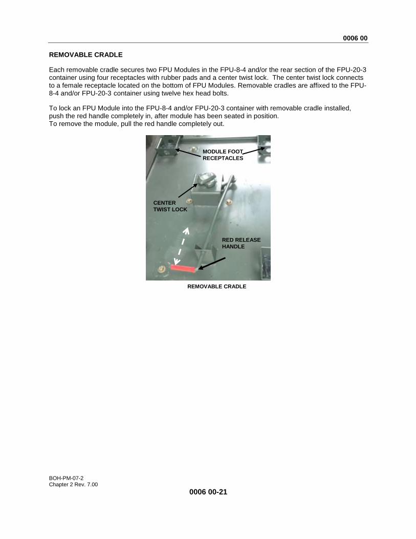
Each removable cradle secures two FPU Modules in the FPU-8-4 and/or the rear section of the FPU-20-3 container using four receptacles with rubber pads and a center twist lock. The center twist lock connects to a female receptacle located on the bottom of FPU Modules. Removable cradles are affixed to the FPU-8-4 and/or FPU-20-3 container using twelve hex head bolts.
To lock an FPU Module into the FPU-8-4 and/or FPU-20-3 container with removable cradle installed, push the red handle completely in, after module has been seated in position. To remove the module, pull the red handle completely out.
RED RELEASE
HANDLE
REMOVABLE CRADLE
MODULE FOOT
RECEPTACLES
CENTER
TWIST LOCK
0006 00
BOH-PM-07-2 Chapter 2 Rev. 7.00
0006 00-22
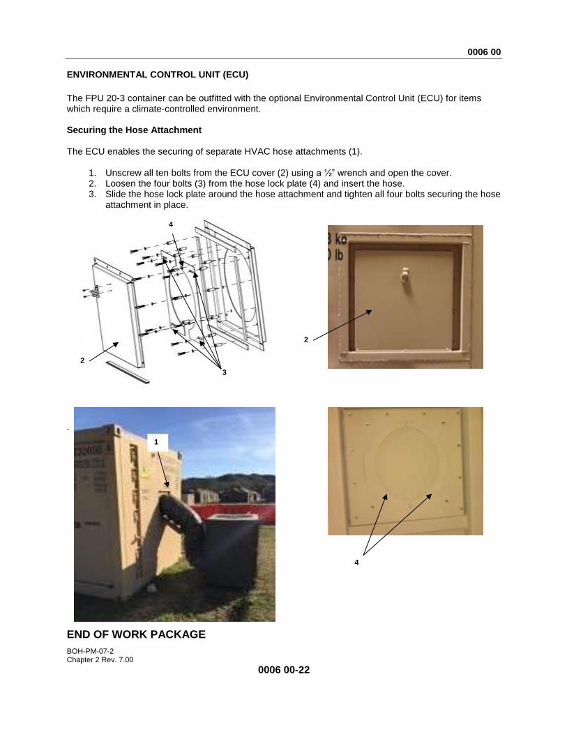
ENVIRONMENTAL CONTROL UNIT (ECU)
The FPU 20-3 container can be outfitted with the optional Environmental Control Unit (ECU) for items which require a climate-controlled environment. Securing the Hose Attachment The ECU enables the securing of separate HVAC hose attachments (1).
1. Unscrew all ten bolts from the ECU cover (2) using a ½” wrench and open the cover. 2. Loosen the four bolts (3) from the hose lock plate (4) and insert the hose. 3. Slide the hose lock plate around the hose attachment and tighten all four bolts securing the hose
attachment in place.
` END OF WORK PACKAGE
2
1
3
4
2
4
0007 00
BOH-PM-07-2 Chapter 2 Rev. 7.00
0007 00-1
OPERATOR INSTRUCTIONS
FPU® SYSTEMS OPERATION MANUAL (INCLUDING REPAIR PARTS & SPECIAL TOOL LIST)
MODELS FPU-8-4/BOH-CARGO-12-3 & FPU-20-3 BOH FPU Field Pack-up Units
LOADING/UNLOADING FPU MODULES
LOADING/ UNLOADING FPU MODULES (FPU-8-4 and the rear section of the FPU-20-3 ONLY)
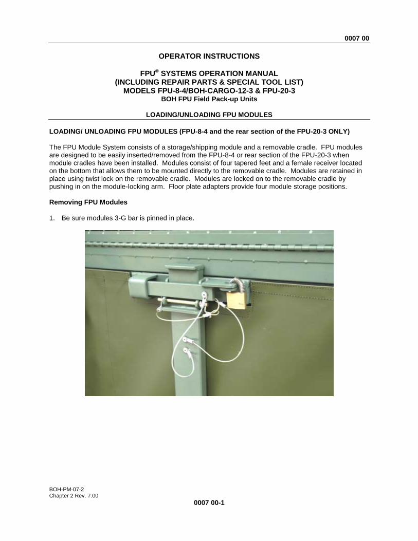
The FPU Module System consists of a storage/shipping module and a removable cradle. FPU modules are designed to be easily inserted/removed from the FPU-8-4 or rear section of the FPU-20-3 when module cradles have been installed. Modules consist of four tapered feet and a female receiver located on the bottom that allows them to be mounted directly to the removable cradle. Modules are retained in place using twist lock on the removable cradle. Modules are locked on to the removable cradle by pushing in on the module-locking arm. Floor plate adapters provide four module storage positions. Removing FPU Modules 1. Be sure modules 3-G bar is pinned in place.
0007 00
BOH-PM-07-2 Chapter 2 Rev. 7.00
0007 00-2
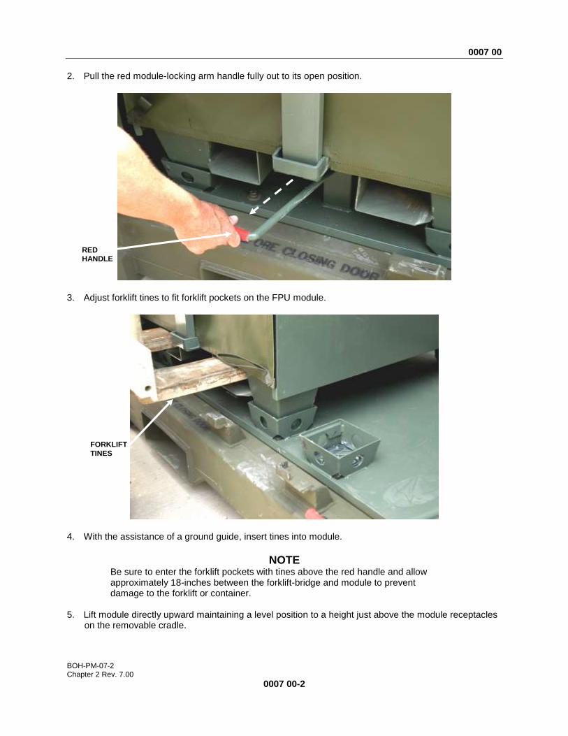
2. Pull the red module-locking arm handle fully out to its open position.
3. Adjust forklift tines to fit forklift pockets on the FPU module.
4. With the assistance of a ground guide, insert tines into module.
NOTE Be sure to enter the forklift pockets with tines above the red handle and allow approximately 18-inches between the forklift-bridge and module to prevent damage to the forklift or container.
5. Lift module directly upward maintaining a level position to a height just above the module receptacles
on the removable cradle.
RED
HANDLE
FORKLIFT
TINES

0007 00
BOH-PM-07-2 Chapter 2 Rev. 7.00
0007 00-3
6. Using ground guide, slowly back out paying close attention to the guide and the upper clearance
between the top of the module and container door cam keeper that protrudes downward from the top of the container frame. The module may have to be raised or lowered during this process if the tilt is too far forward or backwards.
7. Continue backing out until completely clear of the container. 8. Transport to desired drop area and slowly lower until the module is resting fully on the ground. 9. Slowly back away until completely clear of the module. Inserting FPU Modules 1. Be sure the 3-G bar is pinned in place. 2. Be sure red handle on the module-locking arm located on the removable cradle is pulled fully out to
its open position. 3. Adjust forklift tines to fit forklift pockets on the FPU module. 4. With the assistance of a ground guide, insert tines into module. Stop with about 12-inches between
the FPU module and the forklift bridge. This will allow for the clearance needed between the forklift bridge and the container frame when loading the module to prevent the bridge from making contact with the container frame.
5. Using ground guide, lift module and position feet directly above the receptacles located on the
removable cradle at the desired module storage position. 6. Lower the module until it settles into its position (shifting the tines left/right as necessary to align
properly).
0007 00
BOH-PM-07-2 Chapter 2 Rev. 7.00
0007 00-4
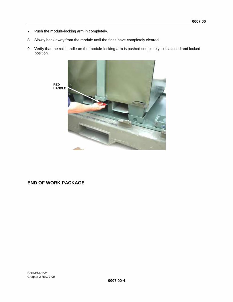
7. Push the module-locking arm in completely. 8. Slowly back away from the module until the tines have completely cleared. 9. Verify that the red handle on the module-locking arm is pushed completely to its closed and locked
position.
END OF WORK PACKAGE
RED
HANDLE

0008 00
BOH-PM-07-2 Chapter 2 Rev. 7.00
0008 00-1
OPERATOR INSTRUCTIONS
FPU® SYSTEMS OPERATION MANUAL (INCLUDING REPAIR PARTS & SPECIAL TOOL LIST)
MODELS FPU-8-4/BOH-CARGO-12-3 & FPU-20-3 BOH FPU Field Pack-up Units
OPERATION UNDER UNUSUAL CONDITIONS
INITIAL SETUP: FPU Downloaded and Operating Maintenance Level Personnel Required
Operator/Crew Two (plus one supervisor)
OPERATION UNDER UNUSUAL CONDITIONS This work package provides instructions for the operation of the FPU under unusual conditions. These include adverse weather, nuclear, biological and chemical attack. Operation in Rain and/or Mud 1. Provide an adequate drainage ditch to prevent standing water around the FPU. 2. Secure all accessories and container during extremely harsh rain.
Operation in Extreme Heat
WARNING
In extreme heat, do not touch metal parts with bare hands. Severe skin damage may result. Operation in Snow, Ice, or Extreme Cold
WARNING
In extreme cold, do not touch metal parts with bare hands. Severe skin damage may result.
0008 00
BOH-PM-07-2 Chapter 2 Rev. 7.00
0008 00-2
Fording The FPU is not watertight. It should never be submerged in any depth of water or material damage may result. When mounted on a trailer or HEMTT truck, hard-bottom water crossings no deeper than approximately two feet can be forded. When in doubt, refer to Unit Standard Operating Procedures.
Interim Nuclear, Biological, and Chemical (NBC) Decontamination Procedures
WARNING
The FPU is NOT designed to be operated in contaminated NBC Environments. Do not operate the FPU in contaminated NBC environments. If possible, cease operation of the FPU system prior to an NBC event and close all doors.
END OF WORK PACKAGE