CHAPTER 2 LITERATURE REVIEW -...
29
7 CHAPTER 2 LITERATURE REVIEW 2.1 INTRODUCTION The current state of knowledge in the area of fixture design and optimization is reviewed in this chapter. However, the Literature on fixture configuration system requires the details in the following areas: Machining errors Fixture design Workpiece model - rigid body model, workpiece-fixture elastic contact model and workpiece elastic model Fixture stability analysis Finite Element Method (FEM) Fixture configuration / Layout design Friction at workpiece-locator contact point Fixture layout optimization methods Clamping force optimization
Transcript of CHAPTER 2 LITERATURE REVIEW -...

7
CHAPTER 2
LITERATURE REVIEW
2.1 INTRODUCTION
The current state of knowledge in the area of fixture design and
optimization is reviewed in this chapter. However, the Literature on fixture
configuration system requires the details in the following areas:
Machining errors
Fixture design
Workpiece model - rigid body model, workpiece-fixture elastic
contact model and workpiece elastic model
Fixture stability analysis
Finite Element Method (FEM)
Fixture configuration / Layout design
Friction at workpiece-locator contact point
Fixture layout optimization methods
Clamping force optimization

8
Number of fixture elements optimization
Genetic Algorithm (GA)
Artificial Neural Networks (ANN)
Design of Experiments (DOE)
2.2 STUDIES RELATED TO MACHINING ERRORS
To begin with, imperfections in manufacturing processes induce
machining errors in components. Machining errors are introduced,
transformed and accumulated when the workpiece is being machined.
Djurdjanovic and Ni (2001) proposed an analytical engineering tool for
machining error analysis and root cause identification. Static form errors in
the peripheral milling of complex thin-walled workpieces have been
predicted by Wan et al (2005) using the finite element formulation.
Also they investigated cutter modelling, finite element discretization of
cutting forces, tool-workpiece coupling and variation of the workpiece’s
rigidity in milling. An error compensation model by considering the
geometric and cutting force induced errors in a 3-axis CNC milling
machine has been proposed (Raksiri and Parnichkun 2004) and the
combination of geometric and cutting force induced errors are modelled by
the combined back propagation neural network. The influence of the wear
of the cutting tool on machining errors has been demonstrated by an
experimental study (Rahou et al 2010) and the circularity error has been
evaluated from the measured profiles using computational geometric
techniques (Venkaiah and Shunmugam 2007). Abdullah et al (2011)
quantified geometric and dimensional error of an Autonomous Underwater
Vehicle (AUV) propeller blade by comparing the profiles obtained from

9
optical method. They reported that the thickness error depends on
deformation ratio of the blade. Wang et al (2005) addressed the special
features of the deformation analysis between complex shaped components
and fixture elements and reported that the deformation error of the fixture
depends on the fixture layout.
Cioata and Kiss (2009) presented analytic models of calculus of
the errors due to contact deformation between locators and workpiece
using the finite element method in order to determine the contact
deformation. Literature related to machining errors concludes that the part
errors are mainly because of machining errors and 20% to 60% of the
overall machining errors are caused due to fixture errors (Cioata and
Kiss 2009).
2.3 STUDIES RELATED TO FIXTURE DESIGN
Fixture is an important element in most of the manufacturing
processes and related to machining errors the role of fixture is very crucial.
Studies pertaining to the design of machining fixture are generally of two
categories i. e. fixture analysis and fixture synthesis. While fixture analysis
deals with forces and deformations, the fixture synthesis is concerned with
the design of fixture configuration to completely immobilize the work part
when subjected to external forces. In the fixture analysis and synthesis, a
concern on the conditions for constraining a workpiece is critical.
The essential requirement of fixturing is the century-old concept and the
same has been extensively studied by Mishra et al (1987) and
Markenscoff et al (1990) in the field of robotics with efficient algorithms to
synthesize positive grips for bounded polyhedral objects. Chou et al (1989)
developed a mathematical theory for automatic configuration of machining
fixtures for prismatic parts. The performance of fixture has been analyzed

10
based on the popular screw theory and engineering mechanics.
The determination of locating and clamping points on workpiece surface
and the determination of clamping forces have also been synthesized.
Trappey and Liu (1990) carried out a literature survey of fixture design
automation and emphasized computer aided fixture design.
In the frictionless case, Lakshminarayana (1978) investigated
the minimum requirements for the form closure of a rigid body and proved
that at least four and seven contacts are necessary to achieve force closure
for 2D and 3D parts respectively. For the same frictionless case, Salisbury
and Roth (1982) demonstrated that a necessary and sufficient condition for
force closure is that a strictly positive linear combination of the primitive
wrenches at contacts is zero and the primitive wrenches span the whole
wrench space. Mishra and Silver (1989) later proved that when friction is
taken into account, three contacts are sufficient in the planar case while
four are adequate in the spatial case. A Projective Spatial Occupancy
Enumeration (PSOE) approach has been applied as a representational and
manipulating scheme for developing algorithms in automatic fixture
configuration by Trappey and Liu (1993). King and Lazaro (1994)
optimized fixture for a particular datum specification and sequence of
operations. Then the fixture system has been analyzed and presented via
the CAD system.
Deiab and Elbestawi (2005) stated that the tangential friction
force plays an important role in fixture configuration design and presented
the results of an experimental investigation of the workpiece-fixture
contact characteristics. Roy and Liao (2002) reported that stability analysis
plays a critical role in determining the applicability of a fixture design and
developed a computational methodology for quantitatively analyzing the
stability of the workpiece in the automated fixture design environment.

11
Liu et al (2004) proposed an algorithm for searching form-closure grasps
of hard fingers on the surface of a three-dimensional object represented by
discrete points with the consideration of both frictional and frictionless
cases. This algorithm starts to search a form-closure grasp from a randomly
selected grasp using an efficient local search procedure until encountering
a local minimum.
Workpiece location error is examined by considering the fixture
geometric error and elastic deformation of the fixture and workpiece due to
fixturing forces (Raghu and Melkote 2005). The deformations at the
contact points are obtained by solving a constrained optimization model
and the experimental validation is also provided for several fixture-
workpiece variable levels using a 3-2-1 machining fixture. Kang and
Peng (2009) reported designing and fabricating fixtures can take up to
10-20% of the total cost of a manufacturing system and reviewed various
approaches used in Computer-Aided Fixture Planning (CAFP). Wang et al
(2010) presented a literature survey of computer aided fixture design and
automation, including their approaches, requirements and working
principles. Related to computer aided fixture design approaches, an
interactive Computer Aided Fixture Design (CAFD) system using the
Gauss Elimination Method for the design of a fixture to hold prismatic
components during machining on a CNC machining centre is described by
Krishnamachary and Reddy (2005). Cecil (1995), Pehlivan et al (2009) and
Nee et al (1987) have reported the other feature-based methodologies in
CAFD. Boyle et al (2011) reviewed over seventy-five CAFD tools and
approaches in terms of the fixture design phases and technology and
reported two research issues that require further effort. The first is that
current CAFD research is segmented in nature and there remains a need to
provide more cohesive fixture design support. Secondly, a greater focus is

12
required on supporting the detailed design of a fixture’s physical structure.
The general situation of research on agile fixture design is summarized and
pointed out the achievements and deficiencies in the field of case-based
agile fixture design (Li et al 2002).
The automation of fixture design and integration of setup and
fixture planning is discussed by Stampfer (2009). Boonsuk and Frank
(2009) presented a methodology for the automated design of a fixturing
system for a rapid machining process. An adaptive fixture design system
with an evolutionary search algorithm has been developed by
Fathianathan et al (2007) to deal with the automatic design changes to meet
the requirements of different domains.
Armillotta et al (2010) described the procedure for kinematic
and tolerance analysis and demonstrated its significance on a sample case
of fixture design. Kinematic analysis verifies that any relative motion
between the part and the worktable is constrained and the tolerance
analysis tests the robustness of part orientation with respect to
manufacturing errors on datum surfaces. Luo et al (2011) developed a
novel model for workpiece positioning analysis by using surface-to-surface
signed distance function and a two-sided quadratic model for fixture
locating analysis. This model has potential applications in fixture design,
tolerance analysis and fault diagnosis. Studies related to fixture design
show that fixture design has received considerable attention in recent years.
However, little attention has been focused on the optimum fixture layout
and clamping forces.

13
2.3.1 AI and Expert System in Fixture Design
In recent years, artificial intelligence (AI) techniques are widely
used in many engineering optimization problems and the usage of AI in the
field of fixture design is also notable. Latombe and Ingrand (1980)
described an expert system for automatic fixture design and Nee et al
(1987) set forth an artificial intelligence system for the development of
fixture design where the basic fixture elements are clamping elements,
positioning and guiding elements, supporting and base elements.
A methodology for the automated design and robotic assembly of modular
fixturing systems based on the integration of state-of-the-art methodologies
is also proposed (Gandhi and Thompson 1987). Ferreira and Liu (1988)
dealt with the automatic generation of workpiece orientations on a machine
for machining operations and Boerma and Kals (1988) described the
automatic selection of the faces for the positioning, clamping and support
of workpieces. An automated fixture-design system using a rule/object-
based approach to group the machining features into appropriate fixture
setups, and to recommend suitable clamping, locating and supporting
points has been developed by Senthilkumar et al (1992). Darvishi and Gill
(1988) presented an exploratory approach to the design of fixtures using an
expert system. An automatic fixture design using a development method
together with a knowledge model is also proposed by Hunter et al (2010)
and a semi-automated methodology to aid the generation of the fixture
design for a given part design is developed by Peng et al (2011).
Studies related to AI in fixture design reveal that the scope of AI is more
intense in the field machining fixture layout design.

14
2.3.2 Modular Fixtures
To improve flexibility in the manufacturing field, the dedicated
fixtures are replaced by modular fixturing systems and these are most
widely used in industry for job and batch production. Liu (1994) provided
a systematic design method to help dedicated fixture users to convert into
modular fixturing system users.
Rong and Bai (1997) designed a modular fixture element
assembly Relationship Graph (MFEARG) to represent combination
relationships between fixture elements and developed algorithms to search
all suitable fixturing unit candidates and mount them into appropriate
positions on a baseplate with interference checking. A modular fixture
design method based on case based reasoning (CBR) algorithm is proposed
by Sun and Chen (2007). Zheng and Qian (2007) introduced a systematic
study of 3-D modular fixtures, particularly for complex objects.
For fixturing the object, seven fixels on the base plates are used to contact
the object in various directions to achieve form closure. The importance of
fixture design automation is emphasized and a general structure of the
automated design system for modular fixture design system is presented
(Vukelic et al 2009) and also a system for computer-aided fixture design
has been verified by Vukelic et al (2011) which comprise of methods and
techniques for fixture design and it allowed fixtures to be designed based
on geometric features of workpiece, process planning and machining
information.

15
2.4 STUDIES RELATED TO FIXTURE CONFIGURATION /
LOCATING SCHEME
The fixture configuration mainly consists of locators and
clamps. The function of each locator is to provide a deterministic location
of the workpiece whereas the function of each clamp is to exert suitable
force on the surface of the workpiece to prevent it from losing contact with
the locators. Based on the classical screw theory several formal methods
for the fixture analysis have been developed. Most of the dedicated fixtures
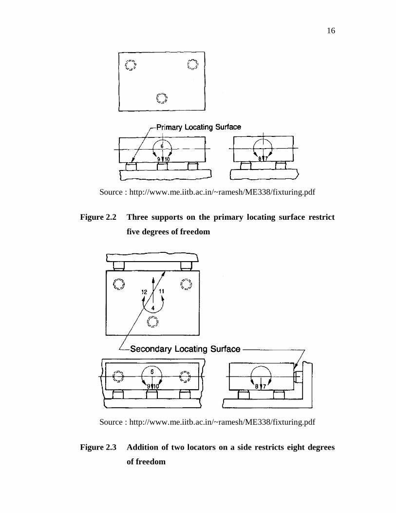
for prismatic parts are designed using the 3-2-1 locating principle.
Here, 3-2-1 refers to 3 locators on the primary locating surface, 2 locators
on the secondary locating surface and 1 locator on the tertiary locating
surface of the workpiece. The twelve degrees of freedom of a free body in
space are shown in Figure 2.1 and out of twelve, nine degrees of freedom
are restricted by using 3-2-1 locating principle as shown in Figures 2.2, 2.3
and 2.4.
Source : http://www.me.iitb.ac.in/~ramesh/ME338/fixturing.pdf
Figure 2.1 Twelve degrees of freedom of a free body
16
Source : http://www.me.iitb.ac.in/~ramesh/ME338/fixturing.pdf
Figure 2.2 Three supports on the primary locating surface restrict
five degrees of freedom
Source : http://www.me.iitb.ac.in/~ramesh/ME338/fixturing.pdf
Figure 2.3 Addition of two locators on a side restricts eight degrees
of freedom

17
Source : http://www.me.iitb.ac.in/~ramesh/ME338/fixturing.pdf
Figure 2.4 Addition of final locator to another side restricts nine
degrees of freedom, completing the 3-2-1 location
Due to its less complexity and effectiveness, the 3-2-1 locating
scheme has been used by most of the researchers. Kang and Peng (2009)
illustrated the 3-2-1 locating method for a prismatic workpiece called valve
body which is shown in Figure 2.5. The valve body is located by three
perpendicular locating planes where the bottom surface of the valve body
forms the primary locating plane, the secondary locating plane is the side
surface contacting two locators and the tertiary locating plane is the side
surface against one locator. Four vertical clamps have been applied on the
top surface. For fixture clamping force optimization, the workpiece-fixture
configuration used by Li and Melkote (2001a) is shown in Figure 2.6
where, L1-L6 are the workpiece-fixture locator contacts and Xg, Yg, Zg,
are the global coordinate frames. They (Li and Melkote 2001) also used 3-
2-1 locating scheme for optimizing fixture design based on workpiece

18
dynamics which is shown in Figure 2.7, where C1-C4 are clamps.
Figure 2.8 shows the N-2-1 fixturing scheme presented by S´anchez et al
(2006) in the Fixture analysis methods for calculating the contact load
distribution and the valid clamping regions in the machining processes.
Source: Kang and Peng (2009)
Figure 2.5 3-2-1 locating method for a valve body
Source: Li and Melkote (2001)
Figure 2.6 Fixture configuration with 3-2-1 locating scheme

19
Source: Li and Melkote (2001)
Figure 2.7 3-2-1 fixturing scheme : L1-L6, locators; C1-C4, clamps
Source: S´anchez et al (2006)
Figure 2.8 N-2-1 fixturing system
The fixture-workpiece system considered to predict workpiece
deformation using the finite element method reported by Siebenaler and
Melkote (2005) is shown in Figure 2.9. In this study, a hollow block of
rectangular section and uniform wall thickness has been restrained by a
3-2-1 fixture layout. A 3-2-1 fixture layout with two clamps for a
rectangular hollow workpiece shown in Figure 2.10 has been used by
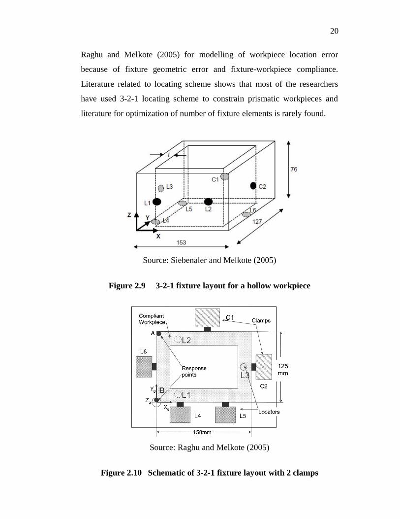
20
Raghu and Melkote (2005) for modelling of workpiece location error
because of fixture geometric error and fixture-workpiece compliance.
Literature related to locating scheme shows that most of the researchers
have used 3-2-1 locating scheme to constrain prismatic workpieces and
literature for optimization of number of fixture elements is rarely found.
Source: Siebenaler and Melkote (2005)
Figure 2.9 3-2-1 fixture layout for a hollow workpiece
Source: Raghu and Melkote (2005)
Figure 2.10 Schematic of 3-2-1 fixture layout with 2 clamps

21
Studies related to locating schemes show that most researchers
concentrated with 3-2-1 layout and indicate that more attention can be
given for optimization of number of locators.
2.5 STUDIES RELATED TO OPTIMUM FIXTURE LAYOUT
DESIGN
Fixture layout is the positioning of fixturing elements such as
locators and clamps on the workpiece. The optimum fixture layout shows
minimum elastic deformation of the workpiece under machining condition.
Menassa and DeVries (1991) proposed a nonlinear optimization algorithm
to determine the optimal positions of the three supports on the primary
locating plane. Here, the support positions are design variables and the
deflection of the workpiece is the objective function. Finite element
analysis (FEA) is used for calculating deflection at selected points as the
design criteria. Trappey et al (1995) used the finite element analysis (FEA)
approach to estimate the dynamic stress-strain behavior of a work-piece
when machining and clamping forces are applied and a mathematical
optimization model has been formulated to minimize the deformation of a
workpiece under the corresponding force effects for a feasible
configuration. De Meter (1995) disclosed an algorithm using min-max
loading criteria for optimal locations of locators and clamps.
Kashyap and DeVries (1999) scheduled a nonlinear
programming method of analysing and optimizing a fixture design for
minimal workpiece deflection during machining. Finite Element Analysis
(FEA) is used for calculating deflection at selected points. Li and Melkote
(1999) used a nonlinear programming method to solve the layout
optimization problem. The method minimizes workpiece location errors
due to localized elastic deformation of the workpiece at the fixturing points

22
by optimally placing the locators and clamps around the workpiece.
The problem of fixture synthesis for fixture elements placement
(Wang 2000) and the problem of characterizing the accuracy of
deterministic localization of fixtures (Wang 2002) have been addressed.
The fixturing tolerance and stability verification have been explored by
Kang et al (2003) with the framework of computer-aided fixture design
verification based on geometric and kinematic models.
Kim and Ding (2004) investigated the various aspects of optimal
fixture layout design in multistation panel assembly processes which are
variation modelling, design criteria and optimization methods. Different
optimization methods have been explored and compared. Wang et al
(2006) established the optimal fixture layout in a global range and it is
especially suitable for the workpiece with complex surfaces. Zhu and Ding
(2007) proposed an efficient algorithm for grasp synthesis and fixture
layout design in discrete domain and it is implemented by solving a single
linear program. Loose et al (2007) have developed a linear model to
describe the dimensional variation propagation of machining processes
through kinematic analysis of the relationships among fixture, datum,
machine geometric errors, and the dimensional quality of the product.
Zhu and Ding (2009) has carried out a comparative study on several widely
used optimality criteria for fixture layout design and Vishnupriyan et al
(2010) optimized machining fixture layout for tolerance requirements
under the influence of locating errors.
Qin et al (2006) have elucidated a general analysis methodology
that is able to characterize the effects of localization source errors based on
the position and orientation of the workpiece. Also they have presented
locating correctness based on Venn diagram and a general algorithm to
determine the locator number and layout (Qin et al 2010). Qin et al (2008)

23
developed a machining-dimension-based locating scheme design approach.
In that approach, first the relationship is established between the machining
dimensions and the Degrees of Freedoms (DOFs) to be constrained.
Then, the fixture locating scheme is established to characterize the practical
constrained DOFs of a workpiece in terms of the known locator number
and positions.
Genetic Algorithm (GA) has been proven to be a useful
technique in solving optimization problems in engineering. Fixture design
has a large solution space and requires a search tool to find the better
design. GAs has been used by few researchers for fixture design and
fixture layout problems. Vallapuzha et al (2002) reviewed the various
optimization methods for optimizing the layout of fixture elements and
reported that the best overall performance is provided by optimization
methods that use both the genetic algorithm and continuous interpolation
for the distribution of boundary conditions.
The application of genetic algorithms to the fixture
configuration optimization problem is presented by Wu and Chan (1996)
while Kulankara et al (2002) expounded GA-based iterative fixture layout
and clamping force design optimization procedure for a compliant
workpiece. The algorithm minimizes the workpiece elastic deformation for
the entire cutting process by alternatively varying the fixture layout and
clamping force. Kaya (2006) has used GA integrated with a commercial
finite element solver to find the optimal locator and clamp positions in 2D
workpiece. Initially, GA is tested by using two test cases and it can be seen
that the GA successfully converges to global minimum. Yildiz and
Ozturk (2006) used hybrid enhanced genetic algorithm to select optimal
machining parameters in turning operation. Then GA is used to optimize
the 2D fixture layout. Prabhakaran et al (2007) posited a fixture layout

24
optimization method that uses genetic algorithm (GA) and Ant Colony
Algorithm (ACA) separately. In this connection, three different number of
node systems are defined on the same workpiece geometry to find the
consistency in the performance of GA and ACA. For all three different
number of node systems, the optimal solution, which is the most minimum
deformation value among the entire possible layout is determined
separately. The solution obtained using GA and ACA for each node system
is compared with their respective optimal solution separately and ACA
reports faster and accurate solutions. ACA is also used by
Padmanaban et al (2009) for machining fixture layout design.
Chen et al (2008) highlighted a fixture layout design and clamping force
optimization procedure based on the GA and Finite Element Method
(FEM). The objectives are minimizing the maximum deformation of the
machined surfaces and maximizing the uniformity of the deformation.
Padmanaban and Prabhakaran (2008) have exemplified an ACA and GA
based fixture layout optimization with the objective of minimizing the
dynamic response of the workpiece.
A non-linear multivariable optimization model formulated by
Ramesh and Jerald (2009) is tested for various stack-up conditions on a
simple mechanical assembly using GA to get optimal tolerance value.
Amaral et al (2005) developed a method for modelling workpiece
boundary conditions and applied loads during a machining process using
FEA. The workpiece boundary conditions are defined by locators and
clamps and the locators are placed in a 3-2-1 fixture configuration and
clamps are modelled as point loads. The workpiece is loaded to model
cutting forces during drilling and milling machining operations.
The literature relevant to fixture layout optimization specifies
that most of the researchers used FEM along with GA to optimize fixture

25
layouts and indicates that more attention can be focussed on workpiece
elastic deformation to reduce part errors.
2.6 STUDIES RELATED TO FIXTURE LAYOUT AND
CLAMPING FORCE OPTIMIZATION
Along with fixture layout optimization only a few researchers
have considered clamping force optimization to minimize machining
errors. Few works are also carried out in determining the minimum
clamping forces, required in the fixture system, because these are critical
and decide the stick/slip conditions during machining. Since FEM is a
better tool for determining the deformation of the workpiece, many
researchers have used FEM with suitable optimization tools for fixture
layout and clamping forces optimization problems.
The influence of clamping preload and machining force on the
surface quality of the machined workpiece is investigated by Liao and
Hu (2001). They developed an integrated finite element analysis model of
the entire fixture-workpiece system and found that the magnitude of
surface error is linearly proportionally affected by the magnitudes of the
external loads (clamping and machining forces). Also the analysis
concluded that based on the material, structure and fixturing scheme of a
workpiece, the clamping preloads and machining forces have different
influences on the machined surface error. De Meter et al (2001) invented a
linear, clamp pre-load (LCPL) model that computes the minimum required
pre-loads necessary to prevent workpiece slip at the fixture-workpiece
joints throughout the machining process.
Li and Melkote (2001) offered a fixture layout and clamping
force optimal synthesis approach that accounts for workpiece dynamics
26
during machining with the objective of minimizing the maximum
positional error at the machining point. Also they (Li and Melkote 2001)
pioneered a new method for determining the optimum clamping forces for
a multiple clamp fixture work-piece system subjected to quasi-static
machining loads and developed an algorithm for clamping force
optimization based on contact mechanics.
Xiong et al (2002) presented a qualitative analysis to minimize
the sum of all normal contact forces and the maximum normal contact
force. The problem of synthesizing robust optimal clamping schemes on
three-dimensional parts with and without friction is addressed by Marin
and Ferreira (2002). They proposed a method to compute optimum
clamping forces and positions on cylindrical faces. Kang and Rong (2003)
introduced a first comprehensive CAFDV framework which uses both
geometric and kinetic models (Kang and Rong 2003c) to verify locating
completeness, locating accuracy (Kang and Rong 2003a), and fixturing
stability (Kang and Rong 2003b). The models have also been used for
locating tolerance assignment and the determination of minimum clamping
force required in machining operations. Raghu and Melkote (2004)
modelled analytically the effect of clamping sequence on the workpiece
location error for a fixture-workpiece system. An algorithmic procedure is
designed to understand the change in forces and deformations as clamps
are applied, whereas Deng and Melkote (2006) endorsed a model-based
framework for determining the minimum required clamping forces that
ensure the dynamic stability of fixtured workpiece during machining.
It consists of a dynamic model for simulating the vibratory behavior during
machining, a geometric model for capturing continuously changing
geometry during machining, a static model for determining the contact
deformation due to clamping, a model for checking dynamic stability and a
27
model determining the optimal set of clamping forces that satisfies the
stability criteria.
Hamedi (2005) has used Artificial Neural Network (ANN) for
clamping force optimization to predict the deformation and it has been
proved that ANN predicts the required output. Aoyama et al (2006)
developed a clamping condition optimization system to determine the
optimum clamping positions and clamping force by analyzing the
deformation of the workpiece model using FEM. The genetic algorithm is
applied to the optimization of clamping positions and the effectiveness is
confirmed. S´anchez et al (2006a) proposed two analysis methods for
fixturing systems in machining to determine the most suitable clamping
regions. Chen et al (2007) established a dual optimization model of fixture
layout and dynamic clamping force for machining the thin-walled
workpieces. Based on the optimal fixture layout dynamic clamping forces
are optimized. The workpiece deformation has been analysed by using
finite element method and a genetic algorithm has been developed to solve
the optimization model. Weifang Chen et al (2008) proffered a fixture
layout design and clamping force optimization procedure based on the GA
and FEM, in which multi objective optimization procedure is used.
The objectives are minimizing the maximum deformation of the machined
surfaces and maximizing the uniformity of the deformation. The ANSYS
software package has been used for FEM calculation of fitness values.
Jiang and Meng (2010) have analyzed the workpiece elastic deformation
caused by clamping force, its location and support location using the case
of Aluminum alloy 6061 part. Sun et al (2011) have analyzed the clamping
process using FEM to optimize fixture layout and clamping force for
minimizing the workpiece deformation via GA.

28
Fixture layout and clamping forces optimization studies express
the fact that FEM and GA are the most common techniques used and so
due importance can be given on the influence of fixture layout and
clamping forces on the overall workpice elastic deformation.
2.7 STUDIES RELATED TO MODELLING AND ANALYSIS
OF WORKPIECE-FIXTURE SYSTEM
Numerous research efforts have been reported in the past
decades for modelling and analysis of machining fixture-workpiece
systems. The majority of prior work treats the fixture-workpiece system as
quasi-static and ignores the system dynamics. In reality, machining
processes such as milling are characterized by periodic forces.
Li and Melkote (1999) modelled the workpiece as elastic in the
contact region and rigid elsewhere. The fixture is assumed to be completely
rigid. The locators are modelled as displacement constraints that prevent
workpiece translation in the normal direction. They modelled the clamping
force as uniformly distributed force acting over the workpiece-clamp
contact area and workpiece is considered as 3D. Static analysis is
conducted to predict the elastic deformation by ignoring machining force.
Li et al (2000) proposed a model for analysing the reaction forces and
moments for machining fixtures with large contact areas and it has been
developed using a contact mechanics approach where the workpiece is
assumed to be elastic in the contact region and the fixture element is
treated as rigid. The model has also been used to determine the minimum
clamping force necessary to keep the workpiece in static equilibrium
during machining. Kishnakumar et al (2002) considered the workpiece as
elastic and the fixturing elements are rigid. Static analysis is considered to
determine the workpiece deformation. Tan et al (2004) described the

29
modelling and analysis of optimal fixturing configurations by the methods
of force closure, optimization, and FEM. Force closure has been employed
to find optimal clamping positions and optimization is used for determining
the minimum clamping forces required to balance the cutting forces.
FEM is used to determine the deformation in the workpiece and fixtures.
Satyanarayana and Melkote (2004) analysed the effects of
different finite element boundary conditions on the deformation and
reaction force predictions for a single fixture-workpiece contact.
They developed specific guidelines for finite element modelling of locator-
workpiece/clamp-workpiece contacts. Song and Rong (2005) proposed a
methodology to characterize fixture system’s geometry constraint status
with focus on under-constraint. Kaya (2006) used dynamic analysis to find
out the deformation of the workpiece under machining. The entire tool path
is discrtized into 13 load steps. The workpiece-fixture model is analysed
with respect to tool movement. The workpiece is assumed to be elastic.
The fixture is assumed to be completely rigid. Prabhakaran et al (2006)
modelled the workpiece-fixture system by considering the workpiece as an
elastic body and fixture as a rigid body. The locators are modelled as
displacement constraints that prevent workpiece translation in the normal
direction. The clamping force is modelled as point force. The workpiece is
considered as 2D by assuming that the workpiece is subjected to plane
stress. Static analysis is used to find out the elastic deformation of the
workpiece under machining. Chen et al (2007) modelled the workpiece-
fixture system as semi-elastic contact model considering friction effect,
where the materials are assumed linearly elastic. Each locator or support is
represented by three orthogonal springs that provide restraints in the X, Y
and Z directions and each clamp is similar to a locator but clamping force

30
in normal direction. The spring in normal direction is called normal spring
and the other two springs are called tangential springs.
The literature pertaining to modelling and analysis of
workpiece-fixture system depicts most of the studies using either
workpiece rigid-body model or workpiece-elastic contact model and the
workpiece elastic deformation caused during machining is rarely
considered.
2.8 STUDIES RELATED TO MODELLING OF MACHINING
FORCES AND MATERIAL REMOVAL EFFECT
The removal of the material during machining alters the
geometry and the structural stiffness of the workpiece, in turn, leads to
higher deformation. Thus, there is a need to consider material removal
effects for achieving realistic results in the dynamic analysis.
Kulankara et al (2002) used FEM to simulate the machining
operation. The machining and clamping forces are considered as point
forces acting over the tool path. Static analysis is performed to simulate the
machining operation in which the material removal effect is not
considered. Kaya and Ozturk (2003) simulated the machining operations
by using a finite-element model. The machining forces are considered as
area force applied over the tool workpiece contact area. The model is
analysed with respect to tool movement and material removal using
element death technique. Three dimensional nonlinear finite element
analysis is carried out. Deng (2006) developed a model-based framework
for analysis and synthesis of the dynamic performance, emphasizing
fixturing dynamic stability, of a machining fixture-workpiece system
accounting for the material removal effect.

31
Kaya (2006) used time-dependent forces to define the
machining operation. The material removal effect is taken into account in
the analysis. The entire tool path is divided into 13 load steps.
The workpiece-fixture model is analysed with respect to tool movement.
The workpiece is assumed to be elastic. The fixture is assumed to be
completely rigid.
These studies represent, in most cases, the workpiece is assumed
as elastic; fixture is assumed as completely rigid; machining and clamping
forces are considered as point forces and material removal effect is
considered by using element death technique.
2.9 STUDIES RELATED TO NUMBER OF FIXTURE
ELEMENTS OPTIMIZATION
Hurtado and Melkote (2002) presented a model for the synthesis
of the fixturing configuration in pin-array type flexible machining fixtures
to keep the workpiece rigid body motion due to fixture elastic deformation
at or below a user-specified value. The minimum clamping loads and the
optimal number, position and dimensions of the pins necessary to achieve
the conformability have also been found. Wang and Pelinescu (2003)
described an approach to optimal design of a fixture layout with the
minimum required number of elements. This approach has been applied to
parts with arbitrary 3-D geometry and is restricted to be within a discrete
domain of locations for placing the fixture elements of nonfrictional
contacts. Liu et al (2007) proposed an optimization method to optimize the
number and positions of the locators in the peripheral milling of a low-
rigidity workpiece simultaneously. First the initial layout of the locators is
determined and based on the initial layout, the number and positions of the
locators are optimized. Qin et al (2010) presented locating correctness

32
based on Venn diagram and a general algorithm to determine the locator
number and layout. On the whole, studies related to number of fixture
elements optimization display very little attention has been shown towards
the number of fixturing elements optimization and most of the researchers
have used 3-2-1 locating principle.
2.10 CONCLUDING REMARKS
Review of the literature in the above areas reveals the
following:
Most of the studies use either the rigid-body model or
workpiece-elastic contact model and these studies do not
consider the workpiece elastic deformation caused during
machining
Only little attention has been focused on the fixture layout and
clamping forces optimization with an objective of minimizing
the dimensional and form errors caused due to workpiece elastic
deformation
In most of the researches finite element method (FEM) has been
mainly used for determining the elastic deformation only at
workpiece-fixture contact points
Most of the studies use linear or nonlinear programming
methods, which often do not give the global optimum solution.
Most of the fixture layout optimization procedures start with an
initial feasible layout. Solutions from these methods depend on
the initial fixture layout. They do not consider the fixture layout
optimization on overall workpiece deformation

33
Though it is more suitable tool in the field of fixture layout
optimization, the application of ANN for the optimization of
machining fixture layout to minimize the deformation of the
workpiece is rarely found in the literature
Most of the studies do not consider the dynamic machining
forces in the fixture layout optimization design to minimize the
dynamic response of the workpiece
Most researchers considered 2D workpiece-fixture system by
ignoring the normal force acting on the workpiece during
machining. Most researchers did not consider the material
removal effects in their analysis. In most cases GA has been
interfaced with FEM for the fixture layout optimization
problems
Most of the researchers have used 3-2-1 locating principle and
the optimization of the number of fixturing elements towards
minimum workpiece elastic deformation is rarely considered
The above listed findings motivated the author to carry out the
research work in the field of fixture layout optimization to minimize the
workpiece elastic deformation caused during machining. The following
sections present the research problem and objectives considered in this
research work.
2.11 RESEARCH PROBLEM
During machining operation, fixtures are used to locate and
constrain a workpiece. The most important criteria for fixturing are
workpiece position accuracy and workpiece deformation. In any
34
manufacturing operation, a certain amount of deformation will occur in
the workpiece due to the clamping and machining forces. Deformation in
the workpiece will lead to dimensional and form errors in the workpiece.
To achieve the specified workpiece dimensions and tolerances, it should be
properly located and clamped. A good fixture design minimizes workpiece
geometric and machining errors by limiting the workpiece elastic
deformation. An ideal fixture design consists of optimal fixture layout,
optimum clamping forces and optimum number of fixturing elements such
as locators and clamps. So, Optimization has three main aspects in fixture
design which are the positions of locators and clamps, number of locators
and clamps and the magnitude of clamping forces. These should be
properly selected and calculated so that the workpiece deformation due to
clamping and cutting forces is minimized and uniformed.
Either the rigid-body model or work piece-elastic contact model
has been used in most of the fixture layout optimization literatures where
the workpiece elastic deformation caused during machining is rarely
considered. Most researchers have used 3-2-1 locating principle where the
number of fixturing elements optimization is rarely considered and the
usage of artificial neural networks is very limited for the optimization of
fixture layout to minimize the overall deformation of the workpiece.
Hence, in this research work, the machining fixture layout,
number of fixturing elements and clamping forces optimization problems
are considered with an objective of minimizing the workpiece elastic
deformation caused during machining.

35
2.12 OBJECTIVES OF THE RESEARCH WORK
The dimensional and form errors induced in the workpiece
during machining are the major influencing factors of the component
quality. To minimize the dimensional and form errors and to enhance the
quality of components fixture design has to be optimized. Based on the
conclusions from literature review, the following research objectives are
framed:
(i) The main aim is to minimize the overall workpiece
elastic deformation during machining in order to
minimize the dimensional and form errors in the
workpiece.
(ii) Optimization of number and position of fixture
elements with optimal clamping forces to minimize
the overall workpiece elastic deformation during
machining.
(iii) Developing a suitable methodology to optimize the
machining fixture layout design with an objective of
minimizing the workpiece elastic deformation.
In this research work, the fixture layout, clamping forces and
number of fixturing elements are optimized using nontraditional algorithms
and mathematical approach in order to meet the research objectives.