Chapter 2, Install Cards and Fiber-Optic Cable€¦ · CHAPTER 2-1 Cisco ONS 15454 Procedure Guide,...
26
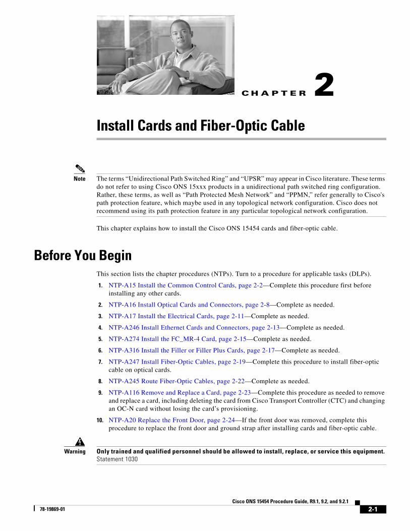
CHAPTER 2-1 Cisco ONS 15454 Procedure Guide, R9.1, 9.2, and 9.2.1 78-19869-01 2 Install Cards and Fiber-Optic Cable Note The terms “Unidirectional Path Switched Ring” and “UPSR” may appear in Cisco literature. These terms do not refer to using Cisco ONS 15xxx products in a unidirectional path switched ring configuration. Rather, these terms, as well as “Path Protected Mesh Network” and “PPMN,” refer generally to Cisco's path protection feature, which maybe used in any topological network configuration. Cisco does not recommend using its path protection feature in any particular topological network configuration. This chapter explains how to install the Cisco ONS 15454 cards and fiber-optic cable. Before You Begin This section lists the chapter procedures (NTPs). Turn to a procedure for applicable tasks (DLPs). 1. NTP-A15 Install the Common Control Cards, page 2-2—Complete this procedure first before installing any other cards. 2. NTP-A16 Install Optical Cards and Connectors, page 2-8—Complete as needed. 3. NTP-A17 Install the Electrical Cards, page 2-11—Complete as needed. 4. NTP-A246 Install Ethernet Cards and Connectors, page 2-13—Complete as needed. 5. NTP-A274 Install the FC_MR-4 Card, page 2-15—Complete as needed. 6. NTP-A316 Install the Filler or Filler Plus Cards, page 2-17—Complete as needed. 7. NTP-A247 Install Fiber-Optic Cables, page 2-19—Complete this procedure to install fiber-optic cable on optical cards. 8. NTP-A245 Route Fiber-Optic Cables, page 2-22—Complete as needed. 9. NTP-A116 Remove and Replace a Card, page 2-23—Complete this procedure as needed to remove and replace a card, including deleting the card from Cisco Transport Controller (CTC) and changing an OC-N card without losing the card’s provisioning. 10. NTP-A20 Replace the Front Door, page 2-24—If the front door was removed, complete this procedure to replace the front door and ground strap after installing cards and fiber-optic cable. Warning Only trained and qualified personnel should be allowed to install, replace, or service this equipment. Statement 1030
Transcript of Chapter 2, Install Cards and Fiber-Optic Cable€¦ · CHAPTER 2-1 Cisco ONS 15454 Procedure Guide,...
Ci78-19869-01
C H A P T E R 2
Install Cards and Fiber-Optic CableNote The terms “Unidirectional Path Switched Ring” and “UPSR” may appear in Cisco literature. These terms do not refer to using Cisco ONS 15xxx products in a unidirectional path switched ring configuration. Rather, these terms, as well as “Path Protected Mesh Network” and “PPMN,” refer generally to Cisco's path protection feature, which maybe used in any topological network configuration. Cisco does not recommend using its path protection feature in any particular topological network configuration.
This chapter explains how to install the Cisco ONS 15454 cards and fiber-optic cable.
Before You BeginThis section lists the chapter procedures (NTPs). Turn to a procedure for applicable tasks (DLPs).
1. NTP-A15 Install the Common Control Cards, page 2-2—Complete this procedure first before installing any other cards.
2. NTP-A16 Install Optical Cards and Connectors, page 2-8—Complete as needed.
3. NTP-A17 Install the Electrical Cards, page 2-11—Complete as needed.
4. NTP-A246 Install Ethernet Cards and Connectors, page 2-13—Complete as needed.
5. NTP-A274 Install the FC_MR-4 Card, page 2-15—Complete as needed.
6. NTP-A316 Install the Filler or Filler Plus Cards, page 2-17—Complete as needed.
7. NTP-A247 Install Fiber-Optic Cables, page 2-19—Complete this procedure to install fiber-optic cable on optical cards.
8. NTP-A245 Route Fiber-Optic Cables, page 2-22—Complete as needed.
9. NTP-A116 Remove and Replace a Card, page 2-23—Complete this procedure as needed to remove and replace a card, including deleting the card from Cisco Transport Controller (CTC) and changing an OC-N card without losing the card’s provisioning.
10. NTP-A20 Replace the Front Door, page 2-24—If the front door was removed, complete this procedure to replace the front door and ground strap after installing cards and fiber-optic cable.
Warning Only trained and qualified personnel should be allowed to install, replace, or service this equipment. Statement 1030
2-1sco ONS 15454 Procedure Guide, R9.1, 9.2, and 9.2.1

Chapter 2 Install Cards and Fiber-Optic CableNTP- A15 Install the Common Control Cards
Warning Filler cards serve three important functions: they prevent exposure to hazardous voltages and currents inside the chassis; they contain electromagnetic interference (EMI) that might disrupt other equipment; and they direct the flow of cooling air through the chassis. Do not operate the system unless all cards and faceplates are in place. Statement 156
NTP-A15 Install the Common Control Cards
Warning During this procedure, wear grounding wrist straps to avoid electrostatic discharge (ESD) damage to the card. Do not directly touch the backplane with your hand or any metal tool, or you could shock yourself. Statement 94
Warning The intra-building ports of the equipment or subassembly is suitable for connection to intra-building or unexposed wiring or cabling only. The intra-building port(s) of the equipment or subassembly must not be metallically connected to interfaces that connect to the OSP or its wiring. These interfaces are designed for use as intra-building interfaces only (Type 2 or Type 4 ports as described in GR-1089-CORE, Issue 4) and require isolation from the exposed OSP cabling. The addition of Primary Protectors is not sufficient protection in order to connect these interfaces metallically to OSP wiring.
Warning The intra-building ports of this card are suitable for connection only to shielded intra-building cabling grounded at both ends.
Caution Always use the supplied ESD wristband when working with a powered ONS 15454. For detailed instructions on how to wear the ESD wristband, refer to the Cisco ONS Electrostatic Discharge (ESD) and Grounding Guide.
Caution If protective clips are installed on the backplane connectors of the cards, remove the clips before installing the cards.
Note If you install a card incorrectly, the FAIL LED flashes continuously.
Purpose This procedure describes how to install the common control cards.
Tools/Equipment Redundant TCC2/TCC2P cards
Redundant XCVT, XC10G, or XC-VXC-10G (cross-connect) cards
AIC-I card (optional)
Prerequisite Procedures NTP-A13 Perform the Shelf Installation Acceptance Test, page 1-31
Required/As Needed Required
Onsite/Remote Onsite
Security Level Provisioning or higher
2-2Cisco ONS 15454 Procedure Guide, R9.1, 9.2, and 9.2.1
78-19869-01

Chapter 2 Install Cards and Fiber-Optic CableNTP- A15 Install the Common Control Cards
Step 1 If you plan to install XCVT cards, review Table 2-1 to determine card/slot compatibility. If you plan to install XC10G or XC-VXC-10G cards, review Table 2-2 on page 2-5 to determine card/slot compatibility.
Step 2 Complete the “DLP-A36 Install the TCC2/TCC2P Cards” task on page 17-37.
Step 3 Complete the “DLP-A37 Install the XCVT, XC10G, or XC-VXC-10G Cards” task on page 17-40.
Step 4 Complete the “DLP-A41 Install the Alarm Interface Controller–International Card” task on page 17-42, as needed.
Note If you install the wrong card in a slot, see the “NTP-A116 Remove and Replace a Card” procedure on page 2-23.
Step 5 Install the traffic cards. To determine the appropriate procedure for a particular card, see the NTP list in the “Before You Begin” section on page 2-1.
In Table 2-1, X indicates that a card is supported in the slot. The multiservice (traffic) slots, Slots 1 to 6 and 12 to 17, include four slots (Slots 5, 6, 12, and 13) that have four times the bandwidth of the other multiservice slots.
Note The XC card is compatible with most cards but does not support features new to Release 5.0 and greater. See the Cisco ONS 15454 Reference Manual for more information about XC card compatibility.
Note For specific slot restrictions for a particular card, consult the card reference section for that card in the Cisco ONS 15454 Reference Manual.
Table 2-1 Card and Slot Compatibility for the XCVT Card
Slot 1 2 3 4 5 6 7 8 9 10 11 12 13 14 15 16 17
Type MS MS MS MS MS MS TCC XC AIC-I XC TCC MS MS MS MS MS MS
TCC2/TCC2P X X
XCVT X X
AIC-I X
DS1-14 X X X X X X X X X X X X
DS1N-141 X X3 X X3 X3 X3 X3 X3 X3 X X3 X3
DS1/E1-56 X X X X X X
DS3-12 X X X X X X2 X2 X X X X X
DS3-12E X X X X X X2 X2 X X X X X
DS3N-12 X3 X3 X X3 X3 X3,2 X3,2 X3 X3 X X3 X3
DS3N-12E X3 X3 X X3 X3 X3,2 X3,2 X3 X3 X X3 X3
DS3I-N-123 X3 X3 X X3 X3 X3 X3 X3 X3 X X3 X3
DS3XM-6 X X X X X X2 X2 X X X X X
DS3XM-12 X X X X X X2 X2 X X X X X
2-3Cisco ONS 15454 Procedure Guide, R9.1, 9.2, and 9.2.1
78-19869-01

Chapter 2 Install Cards and Fiber-Optic CableNTP- A15 Install the Common Control Cards
DS3/EC1-48 Not supported with XCVT cards. Requires XC10G or XC-VXC-10G cards.
EC1-12 X X X X X X2 X6 X X X X X
E100T-12 X X X X X X X X X X X X
E1000-2 X X X X X X X X X X X X
E100T-G X X X X X X X X X X X X
E1000-2-G X X X X X X X X X X X X
CE-100T-8 X X X X X X X X X X X X
CE-1000-4 X X X X
CE-MR-10 X X X X X X X X X X X X
G1K-4 X X X X
ML100-12 X X X X
ML1000-2 X X X X
ML100X-8 Not supported with XCVT cards. Requires XC10G or XC-VXC-10G cards.
ML-MR-10 X X X X X X X X X X X X
OC3 IR 4/STM1 SH 1310
X X X X X X X X X X X X
OC3IR/STM1SH 1310-8
Not supported with XCVT cards. Requires XC10G or XC-VXC-10G cards.
OC12 IR STM4 SH 1310
X X X X X X X X X X X X
OC12 LR/STM4 LH 1310
X X X X X X X X X X X X
OC12 LR/STM4 LH 1550
X X X X X X X X X X X X
OC12 IR/STM4 SH 1310-4
Not supported with XCVT cards. Requires XC10G or XC-VXC-10G cards.
OC48 LR 1550 X X X X
OC48 IR/STM16 SH AS 13104
X X X X
OC48 LR/STM16 LH AS 15504
X X X X
OC48-ELR/STM16 EH 100 GHz
X X X X
OC48 ELR 200 GHz
X X X X
OC192 SR/STM64 IO 1310
Not supported with XCVT cards. Requires XC10G or XC-VXC-10G cards.
Table 2-1 Card and Slot Compatibility for the XCVT Card (continued)
Slot 1 2 3 4 5 6 7 8 9 10 11 12 13 14 15 16 17
Type MS MS MS MS MS MS TCC XC AIC-I XC TCC MS MS MS MS MS MS
2-4Cisco ONS 15454 Procedure Guide, R9.1, 9.2, and 9.2.1
78-19869-01

Chapter 2 Install Cards and Fiber-Optic CableNTP- A15 Install the Common Control Cards
In Table 2-2, X indicates that a card is supported in the slot. The multiservice (traffic) slots, Slots 1 to 6 and 12 to 17, include four slots (Slots 5, 6, 12, and 13) that have four times the bandwidth of the other multiservice slots. The XC10G and XC-VXC-10G cards require the ANSI shelf (5454-SA-ANSI) or the high-density shelf (15454-SA-HD).
Note For specific slot restrictions for a particular card, consult the card reference section for that card in the Cisco ONS 15454 Reference Manual.
OC192 IR/STM64 SH 1550
Not supported with XCVT cards. Requires XC10G or XC-VXC-10G cards.
OC192 LR/STM64 LH 1550
Not supported with XCVT cards. Requires XC10G or XC-VXC-10G cards.
MRC-12 X X X X X X X X X X X X
MRC-2.5G-4 X X X X X X X X X X X X
OC192SR1/STM64IO Short Reach and OC192/STM64 Any Reach (OC192-XFP cards)
Not supported with XCVT cards. Requires XC10G or XC-VXC-10G cards.
FC_MR-4 X X X X
OC192 LR/STM64 LH ITU 15xx.xx
Not supported with XCVT cards. Requires XC10G or XC-VXC-10G cards.
1. This identifies 1:N cards that operate as normal DS1 or DS3 cards when installed in certain slots.
2. This DS3 card cannot be used in this slot if used with a high-density electrical interface assembly (EIA) or in a 1:N configuration.
3. This card can only be used with the XCVT card, not the XC card.
4. The OC48AS will operate in Slots 5, 6, 12, and 13 with the XC/XCVT in R3.4 through R4.6, and the OC48AS will operate in Slots 5, 6, 12, and 13 with the XCVT in R5.0 and later. In Release R3.3 and earlier, OC48AS with XC/XCVT is not supported.
Table 2-1 Card and Slot Compatibility for the XCVT Card (continued)
Slot 1 2 3 4 5 6 7 8 9 10 11 12 13 14 15 16 17
Type MS MS MS MS MS MS TCC XC AIC-I XC TCC MS MS MS MS MS MS
Table 2-2 Card and Slot Compatibility for the XC10G and XC-VXC-10G Cards
Slot 1 2 3 4 5 6 7 8 9 10 11 12 13 14 15 16 17
Type MS MS MS MS MS MS TCC XC AIC-I XC TCC MS MS MS MS MS MS
TCC2/TCC2P X X
XC10G X X
XC-VXC-10G X X
AIC-I X
2-5Cisco ONS 15454 Procedure Guide, R9.1, 9.2, and 9.2.1
78-19869-01

Chapter 2 Install Cards and Fiber-Optic CableNTP- A15 Install the Common Control Cards
DS1-14 X X X X X X X X X X X X
DS1N-14 X1 X1 X X1 X1 X1 X1 X1 X1 X X1 X1
DS1/E1-56 X X X X X X
DS3-12 X X X X X X X X X X X X
DS3-12E X X X X X X X X X X X X
DS3N-12 X1 X1 X X1 X1 X1 X1 X1 X1 X X1 X1
DS3N-12E X1 X1 X X1 X1 X1 X1 X1 X1 X X1 X1
DS3XM-6 X X X X X X X X X X X X
DS3XM-12 X X X X X X X X X X X X
DS3/EC1-48 X X X X X X
EC1-12 X X X X X X X X X X X X
E100T-12 Not supported with the XC10G or XC-VXC-10G cards.
E1000-2 Not supported with the XC10G or XC-VXC-10G cards.
E100T-G X X X X X X X X X X X X
E1000-2-G X X X X X X X X X X X X
CE-100T-8 X X X X X X X X X X X X
CE-1000-4 X X X X X X X X X X X X
CE-MR-10 X X X X X X X X X X X X
G1K-4 X X X X X X X X X X X X
ML100-12 X X X X X X X X X X X X
ML1000-2 X X X X X X X X X X X X
ML100X-8 X X X X X X X X X X X X
ML-MR-10 X X X X X X X X X X X X
OC3 IR 4/STM1 SH 1310
X X X X X X X X X X X X
OC3IR/STM1SH 1310-8
X X X X X X X X
OC12 IR STM4 SH 1310
X X X X X X X X X X X X
OC12 LR/STM4 LH 1310
X X X X X X X X X X X X
OC12 IR/STM4 SH 1310-4
X X X X X X X X
OC12 LR/STM4 LH 1550
X X X X X X X X X X X X
OC48 LR 1550 X X X X
Table 2-2 Card and Slot Compatibility for the XC10G and XC-VXC-10G Cards (continued)
Slot 1 2 3 4 5 6 7 8 9 10 11 12 13 14 15 16 17
Type MS MS MS MS MS MS TCC XC AIC-I XC TCC MS MS MS MS MS MS
2-6Cisco ONS 15454 Procedure Guide, R9.1, 9.2, and 9.2.1
78-19869-01

Chapter 2 Install Cards and Fiber-Optic CableNTP- A15 Install the Common Control Cards
Stop. You have completed this procedure.
OC48 IR/STM16 SH AS 1310
X X X X X X X X X X X X
OC48 LR/STM16 LH AS 1550
X X X X X X X X X X X X
OC48-ELR/STM16 EH 100 GHz
X X X X
OC48 ELR 200 GHz
X X X X
OC192 SR/STM64 IO 1310
X X X X
OC192 IR/STM64 SH 1550
X X X X
OC192 LR/STM64 LH 1550
X X X X
OC192 LR/STM64 LH ITU 15xx.xx
X X X X
FC_MR-4 X X X X X X X X X X X X
OC192SR1/STM64IO Short Reach and OC192/STM64 Any Reach (OC192-XFP cards)
X X X X
MRC_12 X X X X X X X X X X X X
MRC-2.5G-4 X X X X X X X X X X X X
1. This identifies 1:N cards that operate as normal DS1 or DS3 cards when installed in certain slots.
Table 2-2 Card and Slot Compatibility for the XC10G and XC-VXC-10G Cards (continued)
Slot 1 2 3 4 5 6 7 8 9 10 11 12 13 14 15 16 17
Type MS MS MS MS MS MS TCC XC AIC-I XC TCC MS MS MS MS MS MS
2-7Cisco ONS 15454 Procedure Guide, R9.1, 9.2, and 9.2.1
78-19869-01

Chapter 2 Install Cards and Fiber-Optic CableNTP- A16 Install Optical Cards and Connectors
NTP-A16 Install Optical Cards and Connectors
Warning During this procedure, wear grounding wrist straps to avoid ESD damage to the card. Do not directly touch the backplane with your hand or any metal tool, or you could shock yourself. Statement 94
Warning Class I (CDRH) and Class 1M (IEC) laser products. Statement 1055
Warning Invisible laser radiation could be emitted from the end of the unterminated fiber cable or connector. Do not stare into the beam directly with optical instruments. Viewing the laser output with certain optical instruments (for example, eye loupes, magnifiers, and microscopes) within a distance of 100 mm could pose an eye hazard. Statement 1056
Warning Use of controls, adjustments, or performing procedures other than those specified may result in hazardous radiation exposure. Statement 1057
The following warning only applies to OC-192 cards with safety keys.
Warning The laser is on when the card is booted and the safety key is in the on position (labeled 1). The port does not have to be in service for the laser to be on. The laser is off when the safety key is off (labeled 0). Statement 293
Caution Always use the supplied ESD wristband when working with a powered ONS 15454. For detailed instructions on how to wear the ESD wristband, refer to the Cisco ONS Electrostatic Discharge (ESD) and Grounding Guide.
Caution When TCC is rebooted after running the VxWorks command to delete database, perform the following steps:
Purpose This procedure describes how to install optical cards (OC-3, OC-12, OC-48, OC-192, MRC-12, and MRC-2.5G-4). The 15454_MRC-12 (multirate), MRC-2.5G-4, OC192SR1/STM64IO Short Reach, and OC192/STM64 Any Reach (known in CTC as OC192-XFP) cards require small form-factor pluggables (SFPs/XFPs) to provide the fiber interface to the cards. On all other optical cards, the fiber is plugged directly into the card. Install according to site plan, if available.
Tools/Equipment OC-3, OC-12, OC-48, OC-192, MRC-2.5G-4, and MRC-12 cards (as applicable)
Prerequisite Procedures NTP-A15 Install the Common Control Cards, page 2-2
Required/As Needed As needed
Onsite/Remote Onsite
Security Level None
2-8Cisco ONS 15454 Procedure Guide, R9.1, 9.2, and 9.2.1
78-19869-01

Chapter 2 Install Cards and Fiber-Optic CableNTP- A16 Install Optical Cards and Connectors
1) I/O cards, OC3-8, OC12-4, OC48-AS (in low-speed slots),OC192, and MRC-12, need to be plugged out after running the VxWorks command to delete database and before rebooting TCC.
2) I/O cards, OC3-8, OC12-4, OC48-AS (in low-speed slots),OC192, and MRC-12, need to be plugged in after TCC comes to ACTIVE.
The above steps are applicable even in the power cycle of the NODE after running the VxWorks command to delete database on the TCC.
Note If protective clips are installed on the backplane connectors of the cards, remove the clips before installing the cards.
Note To simplify path protection to bidirectional line switched ring (BLSR) conversion and node addition, install optical cards according to a high-speed east (Slots 12 and 13) and west (Slots 5 and 6) configuration. This configuration is not mandatory.
Note During the boot process, an Out-of-Service (OOS) OC-N port will output a Line Alarm Indication Signal (AIS-L) to any In-Service (IS) far-end receivers. See the Cisco ONS 15454 Troubleshooting Guide for further information about the AIS-L condition.
Step 1 If you installed XCVT cards, review Table 2-1 on page 2-3 to determine card/slot compatibility. If you installed XC10G or XC-VXC-10G cards, review Table 2-2 on page 2-5 to determine card/slot compatibility.
Install higher-capacity cards first; for example, install an OC-192 card before installing an OC-48 card. Let each card completely boot before installing the next card.
Note “OC192SR1/STM64IO Short Reach” and “OC192/STM64 Any Reach” are the titles that appear on the faceplates of the OC192-XFP cards. In CTC, the cards are abbreviated as “OC192-XFP.”
Before installing a MRC-12 card, review Table 2-3 for bandwidth limitations based on the slot where the card is installed and the type of cross-connect card installed in the shelf.
Before installing a MRC-2.5G-4 card, review Table 2-4 for bandwidth limitations based on the slot where the card is installed and the type of cross-connect card installed in the shelf.
Table 2-3 Maximum Bandwidth by Shelf Slot for the MRC-12 in Different XC Configurations
XC Card TypeMaximum Bandwidth in Slots 1 through 4 and 12 through 17
Maximum Bandwidth in Slots 5, 6, 12, or 13
XCVT OC-12 OC-48
XC10G/XC-VXC-10G OC-48 OC-192
2-9Cisco ONS 15454 Procedure Guide, R9.1, 9.2, and 9.2.1
78-19869-01

Chapter 2 Install Cards and Fiber-Optic CableNTP- A16 Install Optical Cards and Connectors
Refer to the card’s reference section in the “Optical Cards” chapter of the Cisco ONS 15454 Reference Manual for more information about slot and bandwidth restrictions.
Step 2 Open the card latches/ejectors.
Step 3 Use the latches/ejectors to firmly slide the optical card along the guide rails until the card plugs into the receptacle at the back of the slot. If you install a card incorrectly, the FAIL LED flashes continuously.
Note If you install the wrong card in a slot, complete the “NTP-A116 Remove and Replace a Card” procedure on page 2-23.
Step 4 Verify that the card is inserted correctly and close the latches/ejectors on the card. It is possible to close the latches/ejectors when the card is not completely plugged into the backplane. Ensure that you cannot insert the card any further.
Step 5 Verify the LED activity:
• The red FAIL LED turns on for 20 to 30 seconds.
• The red FAIL LED blinks for 35 to 45 seconds.
• All LEDs blink once and turn off for 5 to 10 seconds.
• The ACT or ACT/STBY LED becomes amber. The signal fail (SF) LED can persist until all card ports connect to their far-end counterparts and a signal is present.
Step 6 If the card does not boot up properly, or the LED activity does not mimic Step 5, check the following:
• When a physical card type does not match the type of card provisioned for that slot in CTC, the card might not boot. If an optical card does not boot, open CTC and ensure that the slot is not provisioned for a different card type before assuming the card is faulty.
• If the red FAIL LED does not turn on, check the power.
• If you insert a card into a slot provisioned for a different card, all LEDs turn off.
• If the red FAIL LED is on continuously or the LEDs behave erratically, the card is not installed properly. Remove the card and repeat Steps 2 to 5.
Step 7 The MRC-12 card requires SFPs and the OC192SR1/STM64IO Short Reach and OC192/STM64 Any Reach (OC192-XFP) cards require XFPs to provide a fiber interface. If you installed any of these cards, complete the “DLP-A469 Install a GBIC or SFP/XFP Device” task on page 21-58. If you want to preprovision the SFPs or XFPs before installing them, complete the “DLP-A461 Preprovision an SFP or XFP Device” task on page 21-43.
Step 8 When you are ready to install fiber, continue with the “NTP-A247 Install Fiber-Optic Cables” procedure on page 2-19.
Stop. You have completed this procedure.
Table 2-4 Maximum Bandwidth by Shelf Slot for the MRC-2.5G-4 in Different Cross-Connect
Configurations
XC Card TypeMaximum Bandwidth in Slots 1 through 4 and 14 through 17
Maximum Bandwidth in Slots 5, 6, 12, or 13
XCVT OC-12 OC-48
XC10G/XC-VXC-10G OC-48 OC-48
2-10Cisco ONS 15454 Procedure Guide, R9.1, 9.2, and 9.2.1
78-19869-01

Chapter 2 Install Cards and Fiber-Optic CableNTP- A17 Install the Electrical Cards
NTP-A17 Install the Electrical Cards
Warning During this procedure, wear grounding wrist straps to avoid ESD damage to the card. Do not directly touch the backplane with your hand or any metal tool, or you could shock yourself. Statement 94
Warning The intra-building ports of the equipment or subassembly is suitable for connection to intra-building or unexposed wiring or cabling only. The intra-building port(s) of the equipment or subassembly must not be metallically connected to interfaces that connect to the OSP or its wiring. These interfaces are designed for use as intra-building interfaces only (Type 2 or Type 4 ports as described in GR-1089-CORE, Issue 4) and require isolation from the exposed OSP cabling. The addition of Primary Protectors is not sufficient protection in order to connect these interfaces metallically to OSP wiring.
Warning The intra-building ports of this card are suitable for connection only to shielded intra-building cabling grounded at both ends.
Caution Always use the supplied ESD wristband when working with a powered ONS 15454. For detailed instructions on how to wear the ESD wristband, refer to the Cisco ONS Electrostatic Discharge (ESD) and Grounding Guide.
Caution Do not install low-density DS-1 cards in the same side of the shelf as DS3/EC1-48 cards.
Caution Do not install a DS3/EC1-48 card in Slots 1 or 2 if you have installed an MXP_2.5G_10G card in Slot 3. Likewise, do not install a DS3/EC1-48 in Slots 16 or 17 if you have installed an MXP_2.5G_10G card in Slot 15. If you do, the cards will interact and cause DS-3 bit errors.
Note When TCC is rebooted after running the VxWorks command to delete database, perform the following steps:
1. I/O card, DS3/EC1, need to be plugged out after running the VxWorks command to delete database and before rebooting TCC.
2. 2) I/O card, DS3/EC1, need to be plugged in after TCC comes to ACTIVE.
Purpose This procedure describes how to install electrical cards (DS-1, DS-3, DS3XM, and EC-1).
Tools/Equipment Electrical cards
Prerequisite Procedures NTP-A15 Install the Common Control Cards, page 2-2
Required/As Needed As needed
Onsite/Remote Onsite
Security Level None
2-11Cisco ONS 15454 Procedure Guide, R9.1, 9.2, and 9.2.1
78-19869-01

Chapter 2 Install Cards and Fiber-Optic CableNTP- A17 Install the Electrical Cards
The above steps are applicable even in the power cycle of the NODE after running the VxWorks command to delete database on the TCC.
Note If protective clips are installed on the backplane connectors of the cards, remove the clips before installing the cards.
Note Install higher-capacity cards first; for example, install a DS-3 card before installing a DS-1 card. Let each card boot completely before installing the next card.
Note If you are installing OC-N, transponder (TXP), or muxponder (MXP) cards, Cisco recommends that you install these before you install electrical cards, as applicable.
Step 1 If you installed XC or XCVT cards, review Table 2-1 on page 2-3 to determine card/slot compatibility. If you installed XC10G or XC-VXC-10G cards, review Table 2-2 on page 2-5 to determine card/slot compatibility.
Step 2 Open the card latches/ejectors.
Step 3 Use the latches/ejectors to firmly slide the card along the guide rails until the card plugs into the receptacle at the back of the slot.
Note If you install the wrong card in a slot, complete the “NTP-A116 Remove and Replace a Card” procedure on page 2-23.
Step 4 Verify that the card is inserted correctly and close the latches/ejectors on the card.
Note It is possible to close the latches/ejectors when the card is not completely plugged into the backplane. Ensure that you cannot insert the card any further.
Step 5 Verify the LED activity:
• The red FAIL LED turns on for 10 to 15 seconds.
• The red FAIL LED blinks for 30 to 40 seconds.
• All LEDs blink once and turn off for 1 to 5 seconds.
• The ACT or ACT/STBY LED turns on. The SF LED can persist until all card ports connect to their far-end counterparts and a signal is present.
Step 6 If the card does not boot up properly, or the LED activity does not mimic Step 5, check the following:
• If the red FAIL LED does not turn on, check the power.
• If you insert a card into a slot provisioned for a different card, all LEDs turn off.
• If the red FAIL LED is on continuously or the LEDs behave erratically, the card is not installed properly. Remove the card and repeat Steps 2 to 5.
2-12Cisco ONS 15454 Procedure Guide, R9.1, 9.2, and 9.2.1
78-19869-01

Chapter 2 Install Cards and Fiber-Optic CableNTP- A246 Install Ethernet Cards and Connectors
Step 7 Continue with the “NTP-A246 Install Ethernet Cards and Connectors” procedure on page 2-13, if necessary.
Stop. You have completed this procedure.
NTP-A246 Install Ethernet Cards and Connectors
Warning During this procedure, wear grounding wrist straps to avoid ESD damage to the card. Do not directly touch the backplane with your hand or any metal tool, or you could shock yourself. Statement 94
Warning Class I (CDRH) and Class 1M (IEC) laser products. Statement 1055
Warning Invisible laser radiation could be emitted from the end of the unterminated fiber cable or connector. Do not stare into the beam directly with optical instruments. Viewing the laser output with certain optical instruments (for example, eye loupes, magnifiers, and microscopes) within a distance of 100 mm could pose an eye hazard. Statement 1056
Warning Use of controls, adjustments, or performing procedures other than those specified may result in hazardous radiation exposure. Statement 1057
Warning The intra-building ports of the equipment or subassembly is suitable for connection to intra-building or unexposed wiring or cabling only. The intra-building port(s) of the equipment or subassembly must not be metallically connected to interfaces that connect to the OSP or its wiring. These interfaces are designed for use as intra-building interfaces only (Type 2 or Type 4 ports as described in GR-1089-CORE, Issue 4) and require isolation from the exposed OSP cabling. The addition of Primary Protectors is not sufficient protection in order to connect these interfaces metallically to OSP wiring.
Warning The intra-building ports of this card are suitable for connection only to shielded intra-building cabling grounded at both ends.
Purpose This procedure describes how to install the Ethernet cards (E100T-12, E100T-G, E1000-2, E1000-2-G, G1K-4, ML100T-12, ML1000-2, ML100X-8, ML-MR-10, CE-100T-8, CE-1000-4, and CE-MR-10).
Tools/Equipment Ethernet cards
Prerequisite Procedures NTP-A15 Install the Common Control Cards, page 2-2
Required/As Needed As needed
Onsite/Remote Onsite
Security Level None
2-13Cisco ONS 15454 Procedure Guide, R9.1, 9.2, and 9.2.1
78-19869-01

Chapter 2 Install Cards and Fiber-Optic CableNTP- A246 Install Ethernet Cards and Connectors
Caution Always use the supplied ESD wristband when working with a powered ONS 15454. For detailed instructions on how to wear the ESD wristband, refer to the Cisco ONS Electrostatic Discharge (ESD) and Grounding Guide.
Note Ethernet interface on the ML-MR-10 Card needs to be shielded and grounded at both ends.
Note If protective clips are installed on the backplane connectors of the cards, remove the clips before installing the cards.
Note If you are installing OC-N, TXP, or MXP cards, Cisco recommends that you install these before you install Ethernet cards.
Step 1 If you installed XC or XCVT cards, review Table 2-1 on page 2-3 to determine card/slot compatibility. If you installed XC10G or XC-VXC-10G cards, review Table 2-2 on page 2-5 to determine card/slot compatibility.
Step 2 Complete the “DLP-A39 Install Ethernet Cards” task on page 17-41. Allow each card to boot completely before installing the next card.
Note If you install the wrong card in a slot, complete the “NTP-A116 Remove and Replace a Card” procedure on page 2-23.
Step 3 Complete the “DLP-A469 Install a GBIC or SFP/XFP Device” task on page 21-58 if you are using E1000-2, E1000-2-G, ML1000-2, ML100X-8, ML-MR-10, CE-1000-4, or CE-MR-10 cards.
Note If you need to remove a GBIC or SFP/XFP, complete the “DLP-A470 Remove GBIC or SFP/XFP Devices” task on page 21-60.
Step 4 Continue with the “NTP-A274 Install the FC_MR-4 Card” procedure on page 2-15 as needed.
Stop. You have completed this procedure.
2-14Cisco ONS 15454 Procedure Guide, R9.1, 9.2, and 9.2.1
78-19869-01

Chapter 2 Install Cards and Fiber-Optic CableNTP- A274 Install the FC_MR-4 Card
NTP-A274 Install the FC_MR-4 Card
Warning During this procedure, wear grounding wrist straps to avoid ESD damage to the card. Do not directly touch the backplane with your hand or any metal tool, or you could shock yourself. Statement 94
Warning Class I (CDRH) and Class 1M (IEC) laser products. Statement 1055
Warning Invisible laser radiation could be emitted from the end of the unterminated fiber cable or connector. Do not stare into the beam directly with optical instruments. Viewing the laser output with certain optical instruments (for example, eye loupes, magnifiers, and microscopes) within a distance of 100 mm could pose an eye hazard. Statement 1056
Warning Use of controls, adjustments, or performing procedures other than those specified may result in hazardous radiation exposure. Statement 1057
Warning High-performance devices on this card can get hot during operation. To remove the card, hold it by the faceplate and bottom edge. Allow the card to cool before touching any other part of it or before placing it in an antistatic bag. Statement 201
Caution Always use the supplied ESD wristband when working with a powered ONS 15454. For detailed instructions on how to wear the ESD wristband, refer to the Cisco ONS Electrostatic Discharge (ESD) and Grounding Guide.
Note If protective clips are installed on the backplane connectors of the cards, remove the clips before installing the cards.
Step 1 If you installed XCVT cards, review Table 2-1 on page 2-3 to determine card/slot compatibility. If you installed XC10G or XC-VXC-10G cards, review Table 2-2 on page 2-5 to determine card/slot compatibility.
Step 2 Open the card latches/ejectors.
Purpose This procedure installs the FC_MR-4 card, also known as the Fibre Channel card.
Tools/Equipment FC_MR-4 card(s)
Prerequisite Procedures NTP-A15 Install the Common Control Cards, page 2-2
Required/As Needed As needed
Onsite/Remote Onsite
Security Level None
2-15Cisco ONS 15454 Procedure Guide, R9.1, 9.2, and 9.2.1
78-19869-01

Chapter 2 Install Cards and Fiber-Optic CableNTP- A274 Install the FC_MR-4 Card
Step 3 Use the latches/ejectors to firmly slide the card along the guide rails until the card plugs into the receptacle at the back of the slot.
Note If you install the wrong card in a slot, complete the “NTP-A116 Remove and Replace a Card” procedure on page 2-23 and install the correct card.
Step 4 Verify that the card is inserted correctly and close the latches/ejectors on the card.
Note It is possible to close the latches/ejectors when the card is not completely plugged into the backplane. Ensure that you cannot insert the card any further.
Step 5 Verify the LED activity:
• The red FAIL LED turns on for 20 to 30 seconds. The ACT LED is amber for 3 to 5 seconds.
• The red FAIL LED blinks for up to 2 minutes.
• The FAIL and ACT LEDs blink once and turn off for 1 to 5 seconds.
• The ACT LED turns on green.
Note If the red FAIL LED does not turn on, check the power.
Note If you insert a card into a slot provisioned for a different card, all LEDs turn off.
Step 6 Complete the “DLP-A469 Install a GBIC or SFP/XFP Device” task on page 21-58 to install GBICs on the FC_MR-4 card.
Note If you need to remove a GBIC or SFP/XFP, complete the “DLP-A470 Remove GBIC or SFP/XFP Devices” task on page 21-60.
Step 7 Continue with the “NTP-A247 Install Fiber-Optic Cables” procedure on page 2-19.
Stop. You have completed this procedure.
2-16Cisco ONS 15454 Procedure Guide, R9.1, 9.2, and 9.2.1
78-19869-01

Chapter 2 Install Cards and Fiber-Optic CableNTP- A316 Install the Filler or Filler Plus Cards
NTP-A316 Install the Filler or Filler Plus Cards
Warning Filler cards serve three important functions: they prevent exposure to hazardous voltages and currents inside the chassis; they contain EMI that might disrupt other equipment; and they direct the flow of cooling air through the chassis. Do not operate the system unless all cards and faceplates are in place. Statement 156
Caution Always use the supplied ESD wristband when working with a powered ONS 15454. For detailed instructions on how to wear the ESD wristband, refer to the Cisco ONS Electrostatic Discharge (ESD) and Grounding Guide.
Figure 2-1 shows general card installation in an ONS 15454 SONET shelf.
Purpose This procedure explains how to install the filler or filler plus cards in any unused traffic or AIC-I card slots (Slots 1 through 6, 9, and 12 through 17). A filler or filler plus card consists of a card with a faceplate attached.
Note There are two types of filler cards. One is not detectable by CTC and has no label on its faceplate. The other is detectable by CTC and has the label FILLER on its faceplate.
Filler cards aid in maintaining proper air flow and electromagnetic interference (EMI) requirements.
Tools/Equipment Filler cardsCisco P/N 15454-FILLER (detectable)Cisco P/N 15454-FILLER Plus (detectable)Cisco P/N 15454-BLANK (non-detectable)
Prerequisite Procedures NTP-A15 Install the Common Control Cards, page 2-2
NTP-A16 Install Optical Cards and Connectors, page 2-8
NTP-A17 Install the Electrical Cards, page 2-11
NTP-A246 Install Ethernet Cards and Connectors, page 2-13
NTP-A274 Install the FC_MR-4 Card, page 2-15
Required/As Needed As needed
Onsite/Remote Onsite
Security Level None
2-17Cisco ONS 15454 Procedure Guide, R9.1, 9.2, and 9.2.1
78-19869-01

Chapter 2 Install Cards and Fiber-Optic CableNTP- A316 Install the Filler or Filler Plus Cards
Figure 2-1 Installing the Filler Plus Card in a ONS 15454 SONET Shelf
Step 1 Open the card ejectors.
Step 2 Slide the card along the guide rails into the correct slot.
Step 3 Close the ejectors.
Step 4 Repeat for any remaining unused card slots.
Step 5 When you log into CTC, verify that the detectable filler or filler plus card appears properly in CTC node view. A non-detectable filler card does not appear in CTC node view.
Stop. You have completed this procedure.
FAN FAILCRIT
MAJMIN
2803
10
Guide railEjector
2-18Cisco ONS 15454 Procedure Guide, R9.1, 9.2, and 9.2.1
78-19869-01

Chapter 2 Install Cards and Fiber-Optic CableNTP- A247 Install Fiber-Optic Cables
NTP-A247 Install Fiber-Optic Cables
Warning Class I (CDRH) and Class 1M (IEC) laser products. Statement 1055
Warning Invisible laser radiation could be emitted from the end of the unterminated fiber cable or connector. Do not stare into the beam directly with optical instruments. Viewing the laser output with certain optical instruments (for example, eye loupes, magnifiers, and microscopes) within a distance of 100 mm could pose an eye hazard. Statement 1056
Warning Use of controls, adjustments, or performing procedures other than those specified may result in hazardous radiation exposure. Statement 1057
The following warning only applies to OC-192 cards with safety keys.
Warning The laser is on when the card is booted and the safety key is in the on position (labeled 1). The port does not have to be in service for the laser to be on. The laser is off when the safety key is off (labeled 0). Statement 293
Warning Laser radiation presents an invisible hazard, so personnel should avoid exposure to the laser beam. Personnel must be qualified in laser safety procedures and must use proper eye protection before working on this equipment. Statement 300
Caution To comply with the Telcordia GR-1089 NEBS, Issue 5 standard, do not use optical fibers with exposed metallic ferrules. Exposed metallic ferrules may result in ESD damage to the system and can be service affecting.
Purpose This procedure installs fiber-optic cables on optical cards according to topology. To attach fiber-optic cable to a GBIC, SFP, or XFP, see the “DLP-A469 Install a GBIC or SFP/XFP Device” task on page 21-58.
Tools/Equipment Fiber-optic cables
Fiber boot
Fiber clips
Prerequisite Procedures NTP-A16 Install Optical Cards and Connectors, page 2-8
NTP-A112 Clean Fiber Connectors, page 15-15
Required/As Needed As needed
Onsite/Remote Onsite
Security Level None
2-19Cisco ONS 15454 Procedure Guide, R9.1, 9.2, and 9.2.1
78-19869-01

Chapter 2 Install Cards and Fiber-Optic CableNTP- A247 Install Fiber-Optic Cables
Caution Do not use fiber loopbacks with the OC192 LR/STM64 LH 1550 or OC192 LR/STM64 LH ITU 15xx.xx card unless you are using a 20-dB attentuator. Never connect a direct fiber loopback. Using fiber loopbacks causes irreparable damage to the OC192 LR/STM64 LH 1550 or OC192 LR/STM64 LH ITU 15xx.xx card.
Caution Do not use fiber loopbacks with the OC192 IR/STM64 SH 1550 card unless you are using a 5-dB attentuator. Never connect a direct, unattenuated fiber loopback. Using unattenuated fiber loopbacks causes irreparable damage to the OC192 IR/STM64 SH 1550 card.
Caution Always use the supplied ESD wristband when working with a powered ONS 15454. For detailed instructions on how to wear the ESD wristband, refer to the Cisco ONS Electrostatic Discharge (ESD) and Grounding Guide.
Note Fiber boots are not recommended for OC192 cards or OC48 AS cards because of the downward angle of the optical ports.
Note You can install the fiber-optic cable immediately after installing the cards, or wait until you are ready to turn up the network. See Chapter 5, “Turn Up a Network.”
Step 1 Test the optical receive levels for the cards installed and attenuate accordingly. See Table 2-5 for the minimum and maximum levels.
Note The levels for the 15454_MRC-12, OC192SR1/STM64IO Short Reach, and OC192/STM64 Any Reach (OC192-XFP) cards are dependent on the particular SFP/XFP installed in a port. The SFPs/XFPs are shown in parentheses in Table 2-5 for these cards.
Table 2-5 Optical Card Transmit and Receive Levels
Card
Transmit Receive
Minimum Maximum Minimum Maximum
OC3 IR 4/STM1 SH 1310 –15 dBm –8 dBm –28 dBm –8 dBm
OC3IR/STM1SH 1310-8 –15 dBm –8 dBm –28 dBm –8 dBm
OC12 IR/STM4 SH 1310 –15 dBm –8 dBm –28 dBm –8 dBm
OC12 LR/STM4 LH 1310 –3 dBm +2 dBm –28 dBm –8 dBm
OC12 LR/STM4 LH 1550 –3 dBm +2 dBm –28 dBm –8 dBm
OC12 IR/STM4 SH 1310-4 –15 dBm –8 dBm –30 dBm –8 dBm
OC48 IR 1310 –5 dBm 0 dBm –18 dBm 0 dBm
OC48 LR 1550 –2 dBm +3 dBm –28 dBm –8 dBm
2-20Cisco ONS 15454 Procedure Guide, R9.1, 9.2, and 9.2.1
78-19869-01

Chapter 2 Install Cards and Fiber-Optic CableNTP- A247 Install Fiber-Optic Cables
OC48 IR/STM16 SH AS 1310 –5 dBm 0 dBm –18 dBm 0 dBm
OC48 LR/STM16 LH AS 1550 –2 dBm +3 dBm –28 dBm –8 dBm
OC48 ELR/STM16 EH 100 GHz –2 dBm 0 dBm –27 dBm at1E-12 BER
–9 dBm
OC48 ELR/STM16 EH 200 GHz –2 dBm 0 dBm –28 dBm –8 dBm
OC192 SR/STM64 IO 1310 –6 dBm –1 dBm –11 dBm –1 dBm
OC192 IR/STM64 SH 1550 –1 dBm +2 dBm –14 dBm –1 dBm
OC192 LR/STM64 LH 1550 +7 dBm +10 dBm –19 dBm –10 dBm
OC192 LR/STM64 LH ITU 15xx.xx +3 dBm +6 dBm –22 dBm –9 dBm
MRC-2.5G-4 –10 dBm –3 dBm –18 dBm –3 dBm
15454_MRC-12 (ONS-SI-2G-S1) –10 dBm –3 dBm –18 dBm –3 dBm
15454_MRC-12 (ONS-SI-2G-I1) –5 dBm 0 dBm –18 dBm 0 dBm
15454_MRC-12 (ONS-SI-2G-L1) –2 dBm 3 dBm –27 dBm –9 dBm
15454_MRC-12 (ONS-SI-2G-L2) –2 dBm 3 dBm –28 dBm –9 dBm
15454_MRC-12 (ONS-SC-2G-30.3 through ONS-SC-2G-60.6)
0 dBm 4 dBm –28 dBm –9 dBm
15454_MRC-12 (ONS-SI-622-I1) –15 dBm –8 dBm –28 dBm –8 dBm
15454_MRC-12 (ONS-SI-622-L1) –3 dBm 2 dBm –28 dBm –8 dBm
15454_MRC-12 (ONS-SI-622-L2) –3 dBm 2 dBm –28 dBm –8 dBm
15454_MRC-12 (ONS-SE-622-1470 through ONS-SE-622-1610)
0 dBm 5 dBm –28 dBm –3 dBm
15454_MRC-12 (ONS-SI-155-I1) –15 dBm –8 dBm –30 dBm –8 dBm
15454_MRC-12 (ONS-SI-155-L1) –5 dBm 0 dBm –34 dBm –10 dBm
15454_MRC-12 (ONS-SI-155-L2) –5 dBm 0 dBm –34 dBm –10 dBm
15454_MRC-12 (ONS_SE-155-1470 through ONS-SE-155-1610)
0 dBm 5 dBm –34 dBm –3 dBm
15454_MRC_12ONS-SI-155-I1-MM=
–9 dBm –14 dBm –14 dBm –5 dBm
15454_MRC_12ONS-SI-622-I1-MM=
–9 dBm –14 dBm –14 dBm –5 dBm
15454_MRC_12ONS-SC-Z3-1470 through ONS-SC-Z3-1610
0 dBm 5 dBm –9 dBm –5 dBm
Table 2-5 Optical Card Transmit and Receive Levels (continued)
Card
Transmit Receive
Minimum Maximum Minimum Maximum
2-21Cisco ONS 15454 Procedure Guide, R9.1, 9.2, and 9.2.1
78-19869-01

Chapter 2 Install Cards and Fiber-Optic CableNTP- A245 Route Fiber-Optic Cables
Step 2 As needed, complete the “DLP-A207 Install Fiber-Optic Cables on the LGX Interface” task on page 19-5.
Step 3 As needed, complete the “DLP-A428 Install Fiber-Optic Cables in a 1+1 Configuration” task on page 21-8.
Step 4 As needed, complete the “DLP-A43 Install Fiber-Optic Cables for Path Protection Configurations” task on page 17-43.
Step 5 As needed, complete the “DLP-A44 Install Fiber-Optic Cables for BLSR Configurations” task on page 17-46.
Step 6 Continue with the “NTP-A245 Route Fiber-Optic Cables” procedure on page 2-22.
Stop. You have completed this procedure.
NTP-A245 Route Fiber-Optic Cables
Step 1 As needed, complete the “DLP-A45 Install the Fiber Boot” task on page 17-48. Fiber boots are required for all OC-N cards except the OC-192,OC192SR1/STM64IO Short Reach and OC192/STM64 Any Reach (OC192-XFP), and OC-48 AS cards.
15454_MRC_12ONS-SE-Z1=
–5 dBm 0 dBm –10 dBm0 dBm–18 dBm0 dBm0 dBm
–23 dBm (OC-3)–23 dBm (OC-12)0 dBm (OC-48)–21 dBm (FC)–22 dBm (GE)
OC192SR1/STM64IO Short Reach (ONS-XC-10G-S1)
–6 dBm –1 dBm –11 dBm –1 dBm
OC192/STM64 Any Reach (ONS-XC-10G-S1)
–6 dBm –1 dBm –11 dBm –1 dBm
OC192/STM64 Any Reach (ONS-XC-10G-I2)
–1 dBm 2 dBm –14 dBm 2 dBm
OC192/STM64 Any Reach (ONS-XC-10G-L2)
0 dBm 4 dBm –24 dBm –7dBm
Table 2-5 Optical Card Transmit and Receive Levels (continued)
Card
Transmit Receive
Minimum Maximum Minimum Maximum
Purpose This procedure describes how to route fiber-optic cables away from the ONS 15454 shelf, including installing fiber boots and fiber clips.
Tools/Equipment None
Prerequisite Procedures NTP-A247 Install Fiber-Optic Cables, page 2-19
Required/As Needed As needed
Onsite/Remote Onsite
Security Level None
2-22Cisco ONS 15454 Procedure Guide, R9.1, 9.2, and 9.2.1
78-19869-01

Chapter 2 Install Cards and Fiber-Optic CableNTP- A116 Remove and Replace a Card
Step 2 Open the fold-down front door on the cable-management tray.
Step 3 Route the fiber-optic cable on the card faceplate through the fiber clip on the faceplate, if provided.
Step 4 If you installed a 15454_MRC-12 card, complete the “DLP-A443 Install the Fiber Clip on 15454_MRC-12 Cards” task on page 21-26. Fiber clips are factory-attached to the faceplate of optical cards except the 15454_MRC-12 cards. The 15454_MRC-12 cards are shipped with two versions of a fiber clip that plug into the faceplate.
Step 5 Route the fiber-optic cables into the cable-management tray.
Step 6 Route the fiber-optic cables out either side of the cable-management tray through the cutouts on each side of the shelf assembly. Use the reversible fiber guides to route cables out the desired side.
Step 7 Close the fold-down front door when all fiber-optic cables in the front compartment are properly routed.
Stop. You have completed this procedure.
NTP-A116 Remove and Replace a Card
Step 1 If you are not logged into CTC and you need to remove a card, remove the card as described in Step 3. When you log into CTC, troubleshoot the mismatched equipment alarm (MEA) with the Cisco ONS 15454 Troubleshooting Guide.
Step 2 If you are logged into CTC, complete one of the following:
• Complete the “DLP-A191 Delete a Card” task on page 18-64 and continue with Step 3.
• Complete the “DLP-A247 Change an OC-N Card” task on page 19-29 to delete a card and replace it with a different OC-N card while maintaining existing provisioning.
Step 3 Physically remove the card:
a. Open the card latches/ejectors.
b. Use the latches/ejectors to pull the card forward and away from the shelf.
Step 4 Insert the new card using one of the following procedures as applicable:
• NTP-A15 Install the Common Control Cards, page 2-2
• NTP-A16 Install Optical Cards and Connectors, page 2-8
• NTP-A17 Install the Electrical Cards, page 2-11
• NTP-A246 Install Ethernet Cards and Connectors, page 2-13
• NTP-A274 Install the FC_MR-4 Card, page 2-15
Step 5 As needed, continue with the “NTP-A247 Install Fiber-Optic Cables” procedure on page 2-19.
Purpose This procedure removes and replaces all cards housed in the ONS 15454 shelf and rack.
Tools/Equipment None
Prerequisite Procedures A card installation procedure
Required/As Needed As needed
Onsite/Remote Onsite
Security Level Provisioning or higher
2-23Cisco ONS 15454 Procedure Guide, R9.1, 9.2, and 9.2.1
78-19869-01

Chapter 2 Install Cards and Fiber-Optic CableNTP- A20 Replace the Front Door
Stop. You have completed this procedure.
NTP-A20 Replace the Front Door
Note Be careful not to crimp any fiber-optic cables that are connected to the optical cards. Some might not have the fiber boot attached.
Step 1 Insert the front door into the hinges on the shelf assembly.
Step 2 Attach one end of the ground strap terminal lug (72-3622-01) to the male stud on the inside of the door. Attach and tighten the #6 Kepnut (49-0600-01) using the open-end wrench (Figure 2-2).
Purpose This procedure replaces the front door and door ground strap after installing cards and fiber-optic cables.
Tools/Equipment #2 Phillips screwdriver
Medium slot-head screwdriver
Small slot-head screwdriver
Prerequisite Procedures NTP-A3 Open and Remove the Front Door, page 1-6
Required/As Needed Required
Onsite/Remote Onsite
Security Level None
2-24Cisco ONS 15454 Procedure Guide, R9.1, 9.2, and 9.2.1
78-19869-01

Chapter 2 Install Cards and Fiber-Optic CableNTP- A20 Replace the Front Door
Figure 2-2 Installing the Door Ground Strap Retrofit Kit
Step 3 Attach the other end of the ground strap to the longer screw on the fiber guide.
a. Attach the lock washer.
b. Attach the terminal lug.
c. Using the open-end wrench, attach and tighten the #4 Kepnut (49-0337-01) on the terminal lug.
Note To avoid interference with the traffic (line) card, make sure the ground strap is in a flat position when the door is open. To move the ground strap into a flat position, rotate the terminal lug counterclockwise before tightening the Kepnut.
Step 4 Replace the left cable-routing channel.
Step 5 Using a Phillips screwdriver, insert and tighten the screws for the cable-routing channel.
Figure 2-3 shows the shelf assembly with the front door and ground strap installed.
7104
8
2-25Cisco ONS 15454 Procedure Guide, R9.1, 9.2, and 9.2.1
78-19869-01

Chapter 2 Install Cards and Fiber-Optic CableNTP- A20 Replace the Front Door
Figure 2-3 Shelf Assembly with Door Ground Strap Retrofit Kit Installed
Step 6 Swing the door closed.
Note The ONS 15454 comes with a pinned hex key tool for locking and unlocking the front door. Turn the key counterclockwise to unlock the door and clockwise to lock it.
Stop. You have completed this procedure. 71
046
Ground strap cable
2-26Cisco ONS 15454 Procedure Guide, R9.1, 9.2, and 9.2.1
78-19869-01


![Threats to Fiber- Optic Infrastructures · lMCI targeting Verizon for brand damage [tap disclosures] ... Defending Fiber Optic InfrastructuresDefending Fiber Optic Infrastructures.](https://static.fdocuments.in/doc/165x107/5acb82e77f8b9ab10a8b583f/threats-to-fiber-optic-targeting-verizon-for-brand-damage-tap-disclosures-.jpg)