Chapter 2 IGES Standard Protocol for Feature Recognition CAD ...
39
Chapter 2 IGES Standard Protocol for Feature Recognition CAD System Emad Abouel Nasr, PhD candaite1 and Ali Kamrani, P ~ D ~ Industrial Engineering Department, Faculty of Engineering, University of Houston, 213 Engineering Building 2, Houston, TX 77204-4008,*[email protected], 2akamarni@uh. edu Abstract: Automatic feature recognition from CAD solid systems highly impacts the level of integration. CAD files contain detailed geometric information of a part, which are not suitable for using in the downstream applications such as process planning. Different CAD or geometric modeling packages store the information related to the design in their own databases. Structures of these databases are different from each other. As a result no common or standard structure has been developed so far, that can be used by all CAD packages. For that reason this chapter proposes an intelligent feature recognition methodology (IFRM) to develop a feature recognition system which has the ability to communicate with various CADICAM systems. The proposed methodology is developed for 3D prismatic parts that are created by using solid modeling package by using constructive solid geometry (CSG) technique as a drawing tool. The system takes a neutral file in Initial Graphics Exchange Specification (IGES) format as input and translates the information in the file to manufacturing information. The boundary (B-rep) geometrical information of the part design is then analyzed by a feature
Transcript of Chapter 2 IGES Standard Protocol for Feature Recognition CAD ...
Chapter 2
IGES Standard Protocol for Feature Recognition CAD System
Emad Abouel Nasr, PhD candaite1 and Ali Kamrani, P ~ D ~ Industrial Engineering Department, Faculty of Engineering, University of Houston, 213
Engineering Building 2, Houston, TX 77204-4008,*[email protected], 2akamarni@uh. edu
Abstract: Automatic feature recognition from CAD solid systems highly
impacts the level of integration. CAD files contain detailed geometric information of a part, which are not suitable for using in the downstream applications such as process planning. Different CAD or geometric modeling packages store the information related to the design in their own databases. Structures of these databases are different from each other. As a result no common or standard structure has been developed so far, that can be used by all CAD packages. For that reason this chapter proposes an intelligent feature recognition methodology (IFRM) to develop a feature recognition system which has the ability to communicate with various CADICAM systems. The proposed methodology is developed for 3D prismatic parts that are created by using solid modeling package by using constructive solid geometry (CSG) technique as a drawing tool. The system takes a neutral file in Initial Graphics Exchange Specification (IGES) format as input and translates the information in the file to manufacturing information. The boundary (B-rep) geometrical information of the part design is then analyzed by a feature
26 Rapid Prototyping: Theory and Practice
recognition program that is created specifically to extract the features from the geometrical information based on a geometric reasoning approach by using object oriented design software which is included in C++ language. A feature recognition algorithm is used to recognize different features of the part such as step, holes, etc. Finally, a sample application description for a workpiece is presented for demonstration purposes.
Key words:
CAD, CAM CAPP, CIM, Feature Recognition, IGES
2.1. History & Overview
The origins of solid modeling are traced back to the key technological inventions of the 1950s which was Computer Graphics and NC machining. These spawned the developments of computer based geometric systems to aid in the description of object's geometry, which is the main activity to design and manufacture of mechanical parts. This resulted research into the development of Computer Aided Design and Computer Aided Manufacturing (CADICAM). Preliminary systems used electronic drafting and wireframe models to represent the shape of three dimensional objects. Subsequent systems developed in the 1960s used polygonal and surface based models which were utilized for a variety of applications in aerospace, marine and automotive industries4.
Until the 1 9 7 0 ~ ~ these models were used in a broad manner. They were merely a collection of lower dimensional entities (polygons, surfaces, lines, curves and points) put together in an unstructured manner to represent a real object. The developments in CAD/CAM led to the crucial questions about the uniqueness and the validity of these models, issues which until then were unimportant from the point of view of computer graphics and its applications. In the late 1 9 7 0 ~ ~ these issues were resolved by the Production Automation Project at the University of Rochester, where the term "solid modeling" was coined". This group developed new mathematical models for representing solids and identified the relevant properties of an informationally complete representation. They also identified the mathe- matical operations that could be used to manipulate these models. After that several other models have been proposed along with different representation schemes14.
In the 1980s, several solid modeling systems were developed and used in the commercial CAD/CAM world, including the automobile, aerospace

Rapid Prototyping: Theory and Practice 27
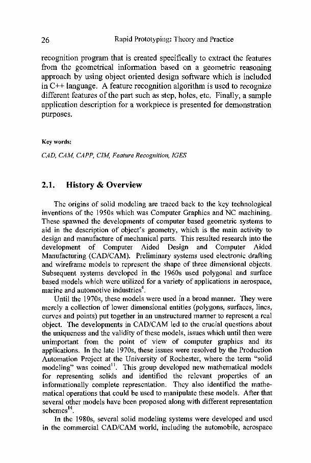
and manufacturing industries. Moreover, many advanced CADICAM applications of solid modeling have emerged such as feature and constraint based modeling, automatic mesh generation for finite element analysis, assembly planning including interference checking, higher dimensional modeling for robotics and collision avoidance, tolerance modeling, automation of process planning tasks, etc. Currently, solid modeling techniques have gained importance in the industry and are also actively pursued as a research field in academic institutions12. Figure 2-1 lists a summary of solid modeling history evolution technology.
To summarize, solid modeling provides a framework to model and represents an object's shape in the computer, and to perform operations. In addition to, a group of application independent geometric tools and algorithms is provided which can be used to query/analyze the model to obtain unambiguous results. These tools can be used or combined with other application specific tools to perform the required task. The issues related to data structures and geometric algorithms, their efficiency, reliability and robustness also form an important aspect of solid modeling1'.
The academic effort in solid modeling utilizes several disciplines in many applications. That is including algebraic geometry and topology, differential geometry and topology, combinatorial topology, computer science, and numerical analysis. Another well established and closely related field is Computer Aided Geometric Design (CAGD) which concentrates on developing techniques for freeforrn surface design used to model curves and surface^'^.
2.2. Standard Data Format
This section presents discussions related to a standard product data format of an object which considered as the most important tool towards the standardization of product data and at the same time towards the compatible exchange of information among various CAD and CAM systems. IGES format is addressed in details as one of the popular standard format.
2.2.1 Data Transfer in CADICAM Systems
Field of data transfer between different CAD/CAM systems is a well established one for a number of years and the paramount importance of CAD/CAM/CAE data transfer between manufacturers and their suppliers and subcontractors has become more apparent. In the early years of CADICAM industry, software packages were developed which were employed as direct translators between different systems. Obviously, these packages were used with great success. However, as the number of
28 Rapid Prototyping: Theory and Practice
CAD/CAM system vendors was increased, the impracticality of using direct translators becomes more apparent. Hence, a few number of neutral format translators developed by various organizations in different countries were introduced into the industrial marketg.
Rapid Prototyping: Theory and Practice 29
Some of these translators were tailor made for specific industries and others were accepted as standard tools by various authorized standard organizations. Some of these standards such as Standard for Exchange of Product data (STEP), Data exchange File (DXF), Product Data Exchange Specifications (PDES) and Initial Graphics Exchange Specifications (IGES) have proved more popular with CADICAM system vendors and users1. 13.
IGES was first developed by National Aeronautical and Space Administration and National Bureau of Standards in 1979. Soon after it was adapted and recognized by American National Standard Institute (ANSI) as a standard tool format. Consequently, IGES has become an acceptable and widely used neutral format translator by many CADICAM system vendors2, 3. Even though some translators are more broadly used than IGES, this neutral format translator has been through many revisions and has proved reasonably a comprehensive tool in transferring data for parts designed by wireframe, surface or solid models. For this book, IGES version 5.3 documentation was closely studied and adopted16.
2.2.2 Initial Graphics Exchange Specifications (IGES)
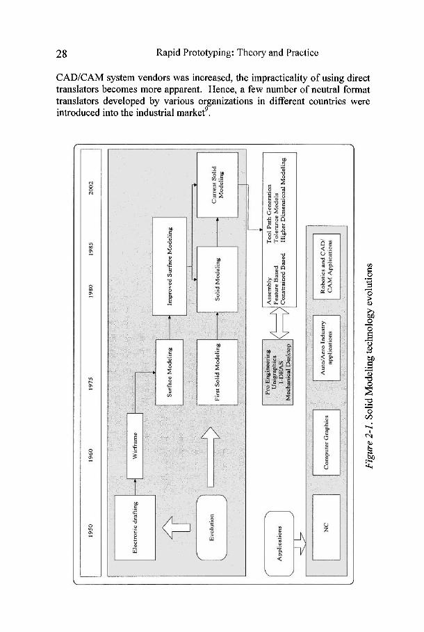
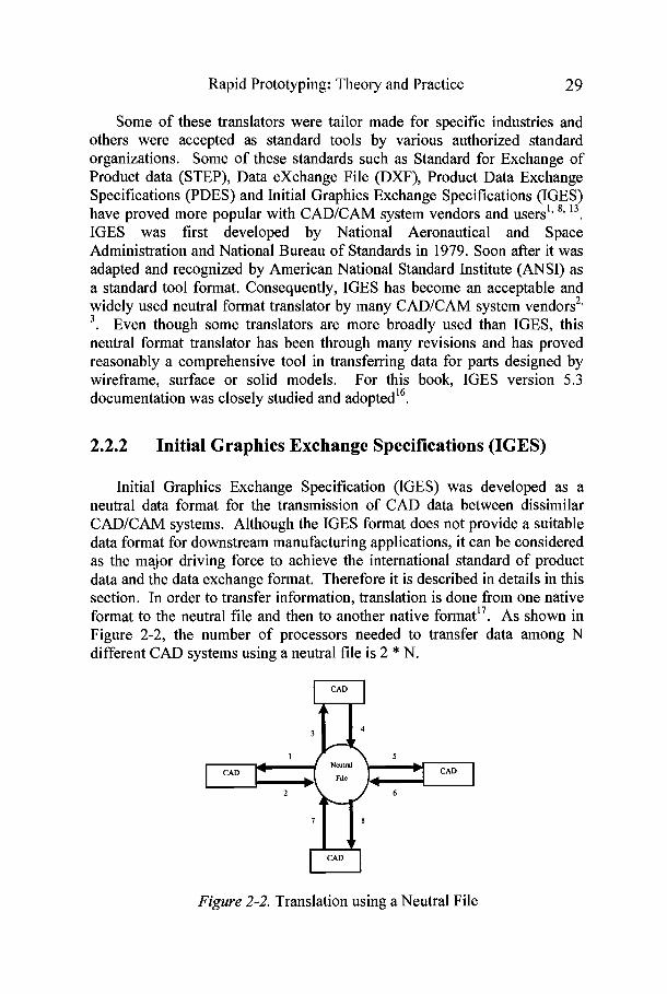
Initial Graphics Exchange Specification (IGES) was developed as a neutral data format for the transmission of CAD data between dissimilar CADICAM systems. Although the IGES format does not provide a suitable data format for downstream manufacturing applications, it can be considered as the major driving force to achieve the international standard of product data and the data exchange format. Therefore it is described in details in this section. In order to transfer information, translation is done from one native format to the neutral file and then to another native formatI7. As shown in Figure 2-2, the number of processors needed to transfer data among N different CAD systems using a neutral file is 2 * N.
Figure 2-2. Translation using a Neutral File
3 0 Rapid Prototyping: Theory and Practice
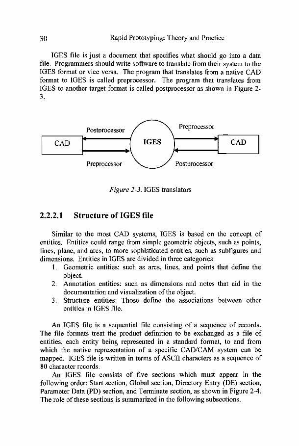
IGES file is just a document that specifies what should go into a data file. Programmers should write software to translate from their system to the IGES format or vice versa. The program that translates from a native CAD format to IGES is called preprocessor. The program that translates from IGES to another target format is called postprocessor as shown in Figure 2- 3.
CAD CAD
Figure 2-3. IGES translators
2.2.2.1 Structure of IGES file
Similar to the most CAD systems, IGES is based on the concept of entities. Entities could range from simple geometric objects, such as points, lines, plane, and arcs, to more sophisticated entities, such as subfigures and dimensions. Entities in IGES are divided in three categories:
Geometric entities: such as arcs, lines, and points that define the object. Annotation entities: such as dimensions and notes that aid in the documentation and visualization of the object. Structure entities: Those define the associations between other entities in IGES file.
An IGES file is a sequential file consisting of a sequence of records. The file formats treat the product definition to be exchanged as a file of entities, each entity being represented in a standard format, to and from which the native representation of a specific CAD/CAM system can be mapped. IGES file is written in terms of ASCII characters as a sequence of 80 character records.
An IGES file consists of five sections which must appear in the following order: Start section, Global section, Directory Entry (DE) section, Parameter Data (PD) section, and Terminate section, as shown in Figure 2-4. The role of these sections is summarized in the following subsections.

Rapid Prototyping: Theory and Practice 3 1
I Start Section I
Figure 2-4. IGES file structure
Global Section Directory Entry Section (DE) Parameter Data Section (PE)
Terminate Section
2.2.2.1.1 Start Section
All geometric entitles are given here
The Start section is a human readable introduction to the file. It is commonly described as a "prologue" to the IGES file. This section contains information such as the names of the sending (source) and receiving (target) CADICAM systems, and a brief description of the product being converted.
2.2.2.1.2 Global Section
The Global section includes information that describe the preprocessor and information needed by the postprocessor to interpret the file. Some of the parameters that are specified in this section are:
Characters used as delimiters between individual entries and between records (usually commas and semicolons respectively), The name of the IGES file itself, Vendor and software version of sending (source) system, Number of significant digits in the representation of integers and single and double precision floating point numbers on the sending systems, Date and time of file generation, Model space scale, Model units, Minimum resolution and maximum coordinate values, Name of the author of IGES file.
2.2.2.1.3 Directory Entry Section (DE)
The DE section is a list of all the entities defined in the IGES file together with certain attributes associated with them. The entry for each entity occupies two 80-character records which are divided into a total bf twenty 8-character fields as shown in Figure 2-5. The first and the eleventh

3 2 Rapid Prototyping: 'Theory and Practicc
(beginning of the second record of any given entity) fields contain the entity type number such as 100 for circle, 110 for lines, etc. The second field contains a pointer to the parameter data entry for the entity in the PD section. The pointer of an entity is simply its sequence number in the DE section. Some of the entity attributes specified in this section are line font, layer number, transformation matrix, line weight, and color.
Column 1 1-8 1 9-16 1 . 1 49-56 1 65-72 1 73-80 Parameter
Line 1 Transformat Sequence -ion Matrix Pointer Switch
Line 2 Entity Sequence Number
Figure 2-5. Structure of Directory Section
2.2.2.1.4 Parameter Data Section (PD)
The PD section contains the actual data defining each entity listed in the DE section as shown in Figure 2-6. For example, a straight line entity is defined by the six coordinates of its two endpoints. While each entity has always two records in the DE section, the number of records required for each entity in the PD section varies from one entity to another (the minimum is one record) and depends on the amount of data. Parameter data are placed in free format in columns 1 through 64. The parameter delimiter (usually a comma) is used to separate parameters and the record delimiter (usually a semicolon) is used to terminate the list of parameters. Both delimiters are specified in the Global section of the IGES file. Column 65 is left blank. Columns 66 through 72 on all PD records contain the entity pointer specified in the first record of the entity in the DE section.
2.2.2.1.5 Terminate Section
The Terminate section contains a single record which specifies the number of records in each of the four preceding sections for checking purposes.

Rapid Prototyping: Theory and Practice 33
Field 1 1 2 3 4 1 5 6 1 7 8 I . I 73-80 I ? XI 1, I I 1 I
Circle
Figure 2-6. Structure of Parameter Data Section
Line
2.3. The Feature Extraction Methodology
100
In this section, a methodology for feature analysis and extraction of prismatic parts for CAM applications is developed and presented. This approach aims to achieve the integration between CAD and CAM. Different CAD or geometric modeling packages store the information related to the design in their own databases. Structures of these databases are different from each other. As a result no common or standard structure has so far developed yet that can be used by all CAD packages. For that reason this research will try to develop an Intelligent Feature Recognition Methodology (IFRM) which has the ability to communicate with the different CAD/CAM systems.
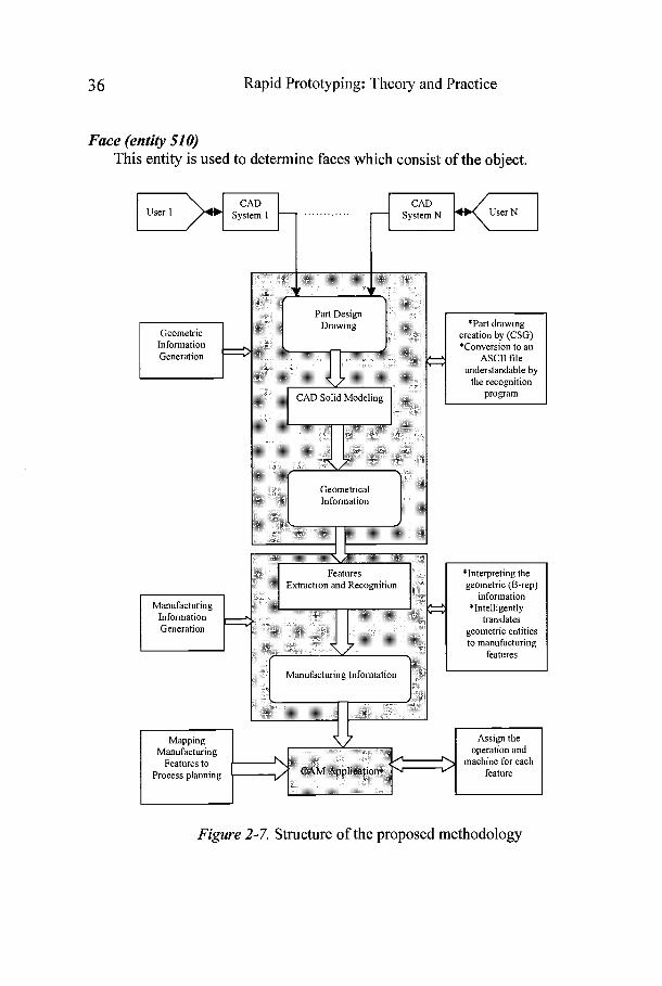
The part design is introduced through CAD software and it is represented as a solid model by using CSG technique as a design tool. The solid model of the part design consists of small and different solid primitives combined together to form the required part design. The CAD software generates and provides the geometrical information of the part design in the form of an ASCII file (IGES) that is used as standard format which provides the proposed methodology the ability to communicate with the different CAD/CAM systems. The boundary (B-rep) geometrical information of the part design is analyzed by a feature recognition program that is created specifically to extract the features from the geometrical information based on the geometric reasoning and object oriented approaches. The feature recognition program is able to recognize these features: slots (through, blind, and round corners), pockets (through, blind, and round corners), inclined surfaces, holes (blind and through) and steps (through, blind, and round corners), etc. These features are called manufacturing information that are mapped to process planning as an application for CAM. Figure 2-7 shows the structure of the proposed methodology.
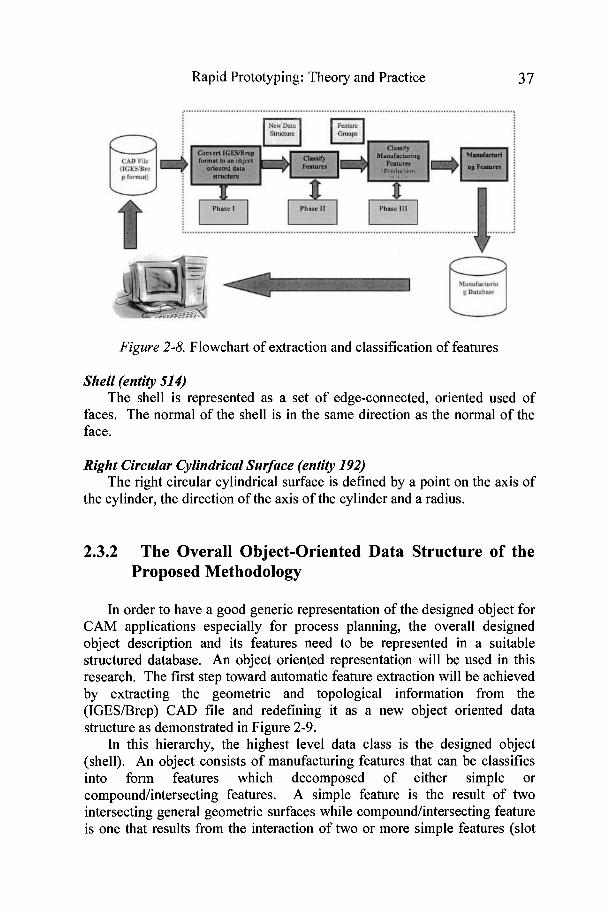
The intelligent feature recognition methodology (IFRM) presented in this chapter consists of three main phases: (1) a data file converter, (2) an object form feature classifier and (3) a manufacturing features classifier (production rules). The first phase converts a CAD data in IGESIB-rep format into a proposed object oriented data structure. The second phase
110
L A 1
(center of circle)
XI Yl z1 (st& point)
XI YI (start point)
x2 y 2
2 2 (end point)
X2 Y2 (end point)
Sequence Number
Sequence Number
34 Rapid Prototyping: Theory and Practice
classifies different part geometric features obtained from the data file converter into different feature groups. The third phase maps the extracted features to process planning's point of view. Figure 2-8 shows a basic flowchart of the proposed system. The sections that follow will describe the steps of feature extraction in details.
2.3.1 Conversion of CAD data files into Object Oriented Data Structure
As mentioned earlier, IGES is a standard file format for the data defining the object drawing in 3D CAD systems in B-rep structure. The entry fields in ICES format consist of an object's geometric and topological information. The geometric information includes the definition of lines, planes, circles, and other geometric entities for a given object, and the topological information defining the relationships between the object's geometric components, for example, in terms of loops (external loop and internal loop).
An external loop gives the location of major geometric shapes and an internal loop represents a protrusion or a depression (pocket or hole) on an external loop. The fundamental IGES entities, which are related to representing a solid in B-rep structure, are discussed in the following subsection to understand how these entities are defined16.
Basic IGES Entities
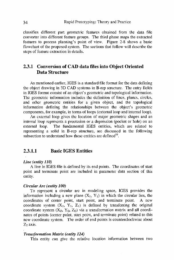
Line (entity 110) A line in IGES file is defined by its end points. The coordinates of start
point and terminate point are included in parameter data section of this entity.
Circular Arc (entity 100) To represent a circular arc in modeling space, IGES provides the
information including a new plane (Xn YT) in which the circular lies, the coordinates of center point, start point, and terminate point. A new coordinate system (XT, YT, &) is defined by transferring the original coordinate system (Xo, Yo, Zo) via a transformation matrix and all coordi- nates of points (center point, start point, and terminate point) related to this new coordinate system. The order of end points is counterclockwise about & axis.
Transformation Matrix (entity 124) This entity can give the relative location information between two

Rapid Prototyping: Theory and Practice 35
coordinate systems, Xo, Yo, Zo coordinate system and XT, YT, ZT coordinate system.
Where
Surface of Revolution (entity 120) A surface is created by rotating the generatrix about the axis of rotation
from the start position to the terminal position. The axis of rotation is a line entity. The generatrix may be a conic arc, line, circular arc, or composite curve. The angles of rotation are counterclockwise about the positive direction of rotation axis.
Point (entity 11 6) A point is defined by its coordinates (X, Y, Z).
Direction (entity 123) A direction entity is a non-zero vector in 3D that is defined by its three
components with respect to the coordinate axes. The normal vector of surface can be determined by this entity.
Plane surface (entity 190) The plane surface is defined by a point on the plane and the normal
direction to the surface.
Vertex List (entity 502) This entity is used to determine the vertex list which contains all the
vertexes of the object.
Edge List (entity 504) This entity is used to determine the edge list which contains all the edges
of the object.
Loop (entity 508) This entity is used to determine the loops which involved in all faces of
the object.
36 Rapid Prototyping: 'I'heory and Practicc
Face (entity 51 0) This entity is used to determine faces which consist of the object.
User 1 User N
geometric entities to manufacturing
Mapping, Assign the
Manufacturing operation and Features to machine for each
Process planning - Figure 2-7. Structure of the proposed methodology
Rapid Prototyping: Theory and Practice 3 7
Figure 2-8. Flowchart of extraction and classification of features
Shell (entity 514) The shell is represented as a set of edge-connected, oriented used of
faces. The normal of the shell is in the same direction as the normal of the face.
Right Circular Cylindrical Surface (entity 192) The right circular cylindrical surface is defined by a point on the axis of
the cylinder, the direction of the axis of the cylinder and a radius.
2.3.2 The Overall Object-Oriented Data Structure of the Proposed Methodology
In order to have a good generic representation of the designed object for CAM applications especially for process planning, the overall designed object description and its features need to be represented in a suitable structured database. An object oriented representation will be used in this research. The first step toward automatic feature extraction will be achieved by extracting the geometric and topological information from the (IGESBrep) CAD file and redefining it as a new object oriented data structure as demonstrated in Figure 2-9.
In this hierarchy, the highest level data class is the designed object (shell). An object consists of manufacturing features that can be classifies into form features which decomposed of either simple or compound/intersecting features. A simple feature is the result of two intersecting general geometric surfaces while compound/intersecting feature is one that results from the interaction of two or more simple features (slot

3 8 Rapid Prototyping: 'I'heory and Practice
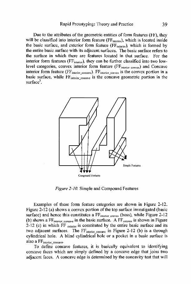
and pocket) as shown in Figure 2-10. Features are further classified into concave or convex as attributes in the generic feature class. Concave features consist of two or more concave faces, and convex features are decomposed of either one or more convex faces or the interaction between other features in the object as shown in Figure 2-1 1
I I I
.................... : ExlonalLarp I : lnrmal Loop j ....................
.................... ....................
Object (Shell)
I Manufacturing feames
I I I
: ConvexLaop j : HybndLoop j : Concave Loop j
Slmple Form Feahlre
Figure 2-9. Hierarchy of classes and attributes of the designed object
Compoundnnlmectmg Form feahlre
Rapid Prototyping: Theory and Practice 3 9
Due to the attributes of the geometric entities of form features (FF), they will be classified into interior form feature (FFintaioI), which is located inside the basic surface, and exterior form feature (FFexterior), which is formed by the entire basic surface with its adjacent surfaces. The basic surface refers to the surface in which there are features located in that surface. For the interior form features (FFintefior), they can be further classified into two low- level categories, convex interior form feature (FFinterior convex) and Concave interior form feature (FFbtefior - concave). FFintefior-convex is the convex portion in a basic surface, while FFinterior concave is the concave geometric portion in the surface3.
-
Features
Compound Features
Figure 2-10. Simple and Compound Features
Examples of these form feature categories are shown in Figure 2-12. Figure 2-12 (a) shows a convex portion of the top surface investigated (basic surface) and hence this constitutes a FFinterior-convex (boss), while Figure 2-12 (b) shows a FFinterior-concave in the basic surface. A FFexterior is shown in Figure 2-12 (c) in which FF ,,fiOr is constituted by the entire basic surface and its two adjacent surfaces. The FFinteriqoncave in Figure 2-12 (b) is a through cylindrical hole. A blind cylindrical hole or a pocket in a basic surface is also a FFinterior-concave
To define concave features, it is basically equivalent to identifling concave faces which are simply defined by a concave edge that joins two adjacent faces. A concave edge is determined by the concavity test that will

40 Rapid Prototyping: Theory and Practice
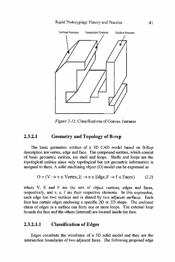
be explained later. In general, the edge is defined by a pair of vertices described in the part drawing properties in terms of coordinates (X, Y, Z). On the other hand, convex features can be defined and classified as either inclined, interaction, or surface as shown in Figure 2-13. Inclined convex features are defined by a set of convex faces which are not parallel or perpendicular to minimal enclosing box. The second type of convex feature (interaction) results from the interaction of two or more features. Surface convex features are features that lie on the minimal enclosing box as seen in Figure 2- 13.
Concave Features
Figure 2-11. Convex and Concave Features and Edges
Basic Surface Basic Surface
Basic
/
Surface
(a) Convex FFinterior (b) Concave FFinterior (c) FFexterior
Figure 2-12. Classification of Interior and Exterior Form Features
Rapid Prototyping: Theory and Practice 4 1
Inclined Features Interaction Features Surface Features
Figure 2-13. Classifications of Convex Features
2.3.2.1 Geometry and Topology of B-rep
The basic geometric entities of a 3D CAD model based on B-Rep description are vertex, edge and face. The compound entities, which consist of basic geometric entities, are shell and loops. Shells and loops are the topological entities since only topological but not geometric information is assigned to them. A solid machining object (0) model can be expressed as
0 = (V -+ v E Vertex, E -+ e E Edge, F -+ f E Faces) (2.2)
where V, E and F are the sets of object vertices, edges and faces, respectively, and v, e, f are their respective elements. In this expression, each edge has two vertices and is shared by two adjacent surfaces. Each face has certain edges enclosing a specific 2D or 3D shape. The enclosed chain of edges in a surface can form one or more loops. The external loop bounds the face and the others (internal) are located inside the face.
2.3.2.1.1 Classification of Edges
Edges constitute the wireframe of a 3D solid model and they are the intersection boundaries of two adjacent faces. The following proposed edge

42 Rapid Prototyping: Theory and Practice
categories facilitate the representation of the proposed methodology as proposed in Figure 2-9. To represent edge categories, the normal vectors of the two faces connected that edge and the edge direction are determined as shown in Figure 2-14. Then by applying the connectivity test that will be discussed later, the edges are classified into convex, concave, and tangent edges as shown in Figure 2-15. Also, the angle between the two faces (@) is determined.
Surface Normal Vectors
Figure 2-14. The surface normal vectors
2.3.2.1.2 Classification of Loops
A loop is the border of a surface. It is also the intersection boundary of the surface with its adjacent surfaces. In this research, a loop is used as a fundamental reference to identify the interior and exterior form features. The loop can be classified as proposed in this research into the external loop and internal loop.
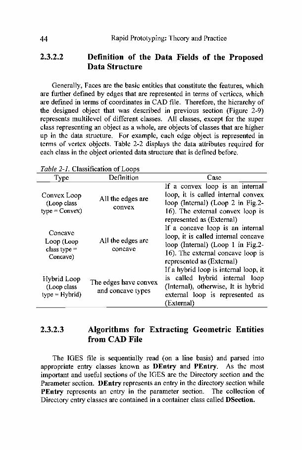
External Loop is the outside boundary of a basic surface of which the loop is investigated, while internal loops are located inside the basic surface. In a basic surface, an external loop is the maximum boundary of the basic surface and the internal loop is the internal interaction boundary of the basic surface with its internal features. In Figure 2-16, there are three loops in the basic surface, one is an external loop and the other two are internal loops, which are the intersection boundaries of the basic surface with its internal convex and concave features. In addition to the loops can be further classified into other different categories as shown in Table 2-1.

Rapid Prototyping: Theory and Practice
(a) Convex Edge (b) Concave Edge
Tangent Edge
(c) Tangent Edge
Figure 2-15. Classification of Edges
External
Internal Loop 1 Internal
Loo
Figure 2-16. Classification of Loops
Loop 2
44 Rapid Prototyping: Theory and Practicc
2.3.2.2 Definition of the Data Fields of the Proposed Data Structure
Generally, Faces are the basic entities that constitute the features, which are further defined by edges that are represented in terms of vertices, which are defined in terms of coordinates in CAD file. Therefore, the hierarchy of the designed object that was described in previous section (Figure 2-9) represents multilevel of different classes. All classes, except for the super class representing an object as a whole, are objects'of classes that are higher up in the data structure. For example, each edge object is represented in terms of vertex objects. Table 2-2 displays the data attributes required for each class in the object oriented data structure that is defined before.
Table 2-1. Classification of Loops Type Definition Case
If a convex loop is an internal Convex Loop loop, it is called internal convex
(Loop class the edges are loop (Internal) (Loop 2 in Fig.2- type = Convex) convex 16). The external convex loop is
represented as (External) If a concave loop is an internal
Concave loop, it is called internal concave Loop (Loop class type =
the edges are loop (Internal) (Loop 1 in Fig.2- concave Concave) 16). The external concave loop is
represented as (External) If a hybrid loop is internal loop, it is called hybrid internal loop
(Loop class type = Hybrid) and concave types external loop is represented as
(External)
2.3.2.3 Algorithms for Extracting Geometric Entities from CAD File
The IGES file is sequentially read (on a line basis) and parsed into appropriate entry classes known as DEntry and PEntry. As the most important and useful sections of the IGES are the Directory section and the Parameter section. DEntry represents an entry in the directory section while PEntry represents an entry in the parameter section. The collection of Directory entry classes are contained in a container class called DSection.

Rapid Prototyping: Theory and Practice 45
Table 2-2. Dej Class Name
Point
Vertex
Verttex-List
Edge
Edge-List
Loop
Surface
Face
Shell
Feature
Compound Feature
iitions of classes and attributes Attribute
X-Coordinates
Z Coordinates Inherits Point Vertex-ID
Vertex List Edge-ID
~ d ~ G ~ ~ e Start-Vertex
Terminate-Vertex Concavity
FaccPointers [2] Loop-Pointers [2]
Dimension Edge-Count Edge List Loop-ID
Loop-Concavity Loop-Type (External or Internal)
Edge-List Face Pointers Surface Type
Face-ID Surface-Pointer External-Loop
Internal-Loop-Count Internal Loop List
Vertex-List Edge-List Loop-List
Surface-List FaccList
Name IGES File Feature-ID
~ e a t u r e - ~ ~ ~ e Feature-Origin
Length Width Height Redius
Face-List Direction
Feature-ID Feature-Ty pe Feature-List
Merging Feature
Type (Real) (Real) (Real) Point
(Integer) (Integer)
Yector of Vertex pointers) (Integer)
(~numeratedConstants) (Vertex Pointer) (Vertex Pointer)
(Enumerated Constants) (Array of Face Pointers) (Array of Loop Pointers)
(real) (Integer)
(Vector of Edge Pointer) (Integer)
(~numerated~onstants) (Enumerated Constants)
(A list of edges) (Pointer to face class)
(Enumarated Constants) Number
(Pointer to the Surface) (Loop Pointer)
Number (Vector of Loop Pointers)
Object of Vertex-List class) (Object of Edge-List class) (Vector of Loop Pointers)
Vector of Surface Pointers) (Vector of Face Pointers
(String) Object of IGES File Class)
(Number) (Enumerated constants)
(Vertex Pointer) (Real) (Real) (Real) (Real)
(Vector of Face Pointers (An object of Point Class)
(Number) (Enumerated constants)
Vector of Feature Pointers) (Integer)

46 Rapid Prototyping: Theory and Practice
Similarly, the Parameter entry classes are contained in the PSection class. A Parser class object is created using these classes to parse the information present in the entries and classifl the information into different classes that are used to represent different entities of the diagram described by the IGES file. Two algorithms for extraction of data from the IGES file into a proper set of data structures are defined as follows:
2.3.2.3.1 Algorithm for extracting entries from directory and parameter sections
N Algorithm to extract the directory entries /I and the parameter section entries from the iges file. /I This process takes place during the construction of an object of IGESFile class. 11 Each such object represents one IGES file. 1. Create a file descriptor IgesFile 2. Create an empty dsectionl class (container to store dEntry objects). 3. Create an empty psectionl class (container to store pEntry objects). 4. Open the Iges file for reading using IgesFile file descriptor
11 Read the file to scan and extract the directory and parameter sections. 5. While ReadLine linel from the Igesfile
5.1 If linel belongs to Directory section 5.1.1 If line 1 is the first line of Dsection
5.1.1.1 Set dIndex to 1 5.1.2 ReadLine line2 from the Igesfile 5.1.3 Create an object dEntryl of class DEntry 5.1.4 Set dEntry 1 index using dIndex 5.1.5 Initialize dEntryl using string Linel+Line2. 5.1.6 Add dEntry 1 to dsectionl class 5.1.7 Set dIndex = dIndex + 1
5.2 If linel belongs to Parameter Section 5.2.1 If linel is the first line of PSection
5.2.1.1 Set pIndex to 1 5.2.2 Create an empty string Line2 5.2.3 while pEntry data incomplete
5.2.3.1 ReadLine Line3 from the Igesfile 5.2.3.2 Append Line3 to Line2
5.2.4 Create an object pEntry1 of class PEntry 5.2.5 Set pEntryl index equal to pIndex 5.2.6 Initialize pEntry 1 using string Line 1 +Line2 5.2.7 Add pEntryl to psectionl class 5.2.8 Set pIndex = pIndex + 1

Rapid Prototyping: Theory and Practice
5.3 If line1 belongs to Terminate Section 5.4 exit while loop
6 End of while loop
2.3.3.3.2 Algorithm for extracting the basic entities of the designed part
// Part-extraction module, contained in the Shell class. 11 This module extracts entities and groups them into lists 11 For example: it creates a list of all Faces in the object represented by the IGES file. Procedure to extract entities. 1 Create an object vertexList1 of vertexList class 2 Create an object edgeListl of edgeList class 3 Create a vector of pointers loop List to Loop class 4 Create a vector of pointers face List to Face class 5 Begin parsing entities from the IGES File object
5.1 Initialize counter i=l 5.2 For i=l to size of dsectionl object from IGES File object 5.3 dEntryl = DEntry object of index i from dsectionl 5.4 if dEntryl is a vertex list
5.4.1 pEntryl = PEntry object pointed to by dEntryl, obtained from psectionl of corresponding IGES File object
5.4.2 Initialize counter j=l 5.4.3 For each vertex present in the pEntryl object do 5.4.4 Instantiate a new vertexl object of class Vertex 5.4.5 Assign id as j to vertexl. 5.4.6 Initialize the object with vertex data from pEntryl 5.4.7 Add to vertexList1 a pointer to vertexl 5.4.8 Increment j by 1 5.4.9 End of For loop
5.5 End For 5.6 Initialize counter i=l 5.7 For i=l to size of dsectionl object from IGES File object 5.8 dEntryl = DEntry object of index i from dSection1 5.9 If dEnryl is an edge list
5.9.1 pEntryl = PEntry object pointed to by dEntryl , obtained from psectionl of corresponding IGES File object
5.9.2 Initialize counter j = 1 5.9.3 For each edge present in the pEntryl class do
Rapid Prototyping: 'Theory and Practice
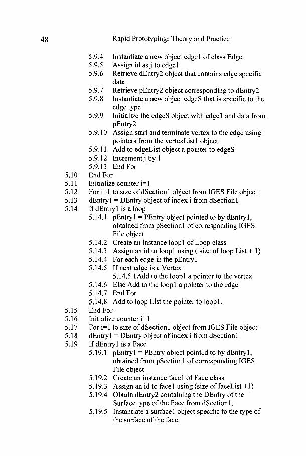
5.9.4 Instantiate a new object edgel of class Edge 5.9.5 Assign id as j to edgel 5.9.6 Retrieve dEntry2 object that contains edge specific
data 5.9.7 Retrieve pEntry2 object corresponding to dEntry2 5.9.8 Instantiate a new object edges that is specific to the
edge type 5.9.9 Initialize the edges object with edgel and data from
pEntry2 5.9.10 Assign start and terminate vertex to the edge using
pointers from the vertexList1 object. 5.9.1 1 Add to edgeList object a pointer to edges 5.9.12 Increment j by 1 5.9.13 EndFor End For Initialize counter i=l For i=l to size of dSectionl object from IGES File object dEntryl = DEntry object of index i from dSectionl If dEntryl is a loop 5.14.1 pEntry 1 = PEntry object pointed to by dEntry 1,
obtained from pSection1 of corresponding IGES File object
5.14.2 Create an instance loopl of Loop class 5.14.3 Assign an id to loopl using ( size of loop List + 1) 5.14.4 For each edge in the pEntry 1 5.14.5 If next edge is a Vertex
5.14.5.1 Add to the loop 1 a pointer to the vertex 5.14.6 Else Add to the loopl a pointer to the edge 5.14.7 EndFor 5.14.8 Add to loop List the pointer to loop 1. End For Initialize counter i=l For i=l to size of dSectionl object from IGES File object dEntryl = DEntry object of index i from dSectionl If dEntryl is a Face 5.19.1 pEntryl = PEntry object pointed to by dEntryl,
obtained from pSection1 of corresponding IGES File object
5.19.2 Create an instance facel of Face class 5.19.3 Assign an id to facel using (size of faceList +1) 5.19.4 Obtain dEntry2 containing the DEntry of the
Surface type of the Face from dSectionl. 5.19.5 Instantiate a surface 1 object specific to the type of
the surface of the face.
Rapid Prototyping: Theory and Practice 49
5.19.6 Add to face 1 a pointer to that surface object 5.19.7 For each Loop on the Surface
5.19.7.lAdd to facel a pointer to loop object from loop List that represents this loop.
5.19.7.2For each Edge in the loop add a pointer to face 1.
5.19.8 EndFor 5.19.9 Add to face List the pointer to facel
5.20 End For 6 End of extract entities procedure.
2.3.3.4 Extracting Form Features from CAD Files
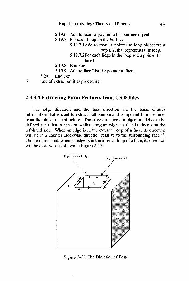
The edge direction and the face direction are the basic entities information that is used to extract both simple and compound form features from the object data structure. The edge directions in object models can be defined such that, when one walks along an edge, its face is always on the left-hand side. When an edge is in the external loop of a face, its direction will be in a counter clockwise direction relative to the surrounding face5' 6 .
On the other hand, when an edge is in the internal loop of a face, its direction will be clockwise as shown in Figure 2-17.
Edge Direction for Ft Edge Direction for FI
Figure 2-1 7. The Direction of Edge
5 0 Rapid Prototyping: 'Theory and Practice
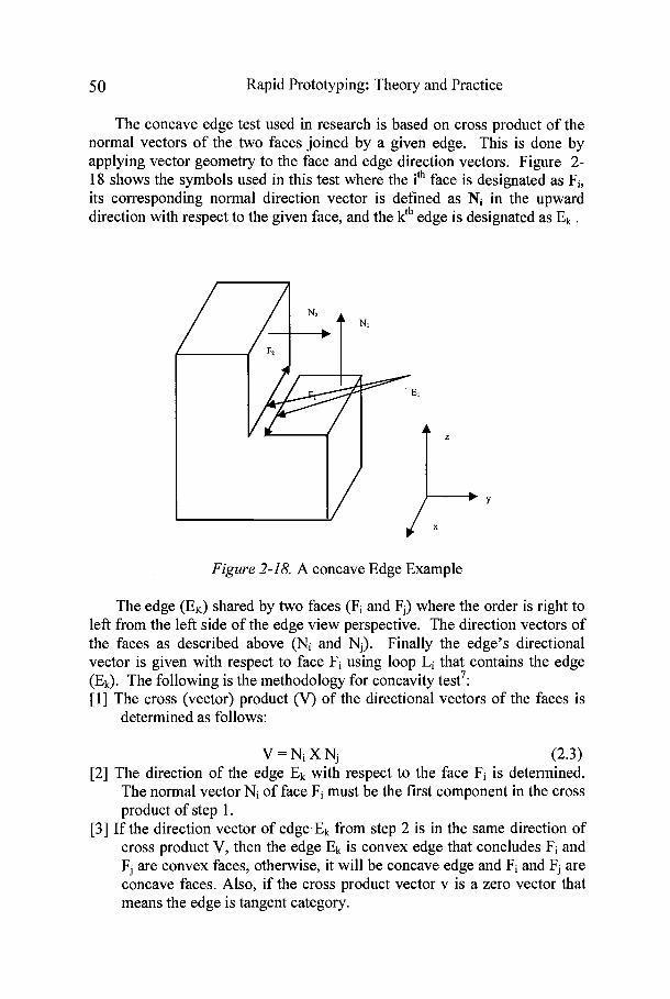
The concave edge test used in research is based on cross product of the normal vectors of the two faces joined by a given edge. This is done by applying vector geometry to the face and edge direction vectors. Figure 2- 18 shows the symbols used in this test where the ith face is designated as Fi, its corresponding normal direction vector is defined as Ni in the upward direction with respect to the given face, and the kth edge is designated as Ek .
Figure 2-18. A concave Edge Example
The edge (EK) shared by two faces (Fi and Fj) where the order is right to left from the left side of the edge view perspective. The direction vectors of the faces as described above (Ni and Nj). Finally the edge's directional vector is given with respect to face Fi using loop Li that contains the edge (Ek). The following is the methodology for concavity test7: [I] The cross (vector) product (V) of the directional vectors of the faces is
determined as follows:
V = N i X N j (2.3) [2] The direction of the edge Ek with respect to the face Fi is determined.
The normal vector Ni of face Fi must be the first component in the cross product of step 1.
[3] If the direction vector of edge,Ek from step 2 is in the same direction of cross product V, then the edge Ek is convex edge that concludes Fi and Fj are convex faces, otherwise, it will be concave edge and Fi and Fj are concave faces. Also, if the cross product vector v is a zero vector that means the edge is tangent category.

Rapid Prototyping: Theory and Practice 5 1
2.3.3.4.1 An Example for identifying the concave edgelfaces
The following is an example for identifying the concave edgelfaces by using the example in Figure 2-18:
1. Find the face normal vectors N1 = [0 0 11 and N2 = [0 1 01. 2. Find the edge direction vector for El with respect to F1 = [ l 0 01 3. Find the cross product (V) = [0 0 11 X [0 1 01 = [-1 0 01 4. The edge direction of El and V have the opposite direction, so the
edge El is a concave edge and F1 and F2 are concave faces.
This procedure will be done on all the edges of the object to define the concave or convex faces. Moreover, concave features will be identified by the premise that concave faces include at least one concave edge with adjacent concave faces forming a concave face group. Each concave face group defines a concave feature. Similarly, adjacent convex faces form a convex face group.
2.3.3.4.2 Algorithm for determining the concavity of the edge
The following algorithm is used to find the concavity of a line entity. This algorithm is used by the Line class to find the entities.
2 concavity = UNKNOWN 3 If facel surface type == PLANE and face2 surface type == PLANE
3.1.1 Assign crossDir = cross product of facel normal vector and face2 normal vector
3.2 If crossDir == 0 3.2.1 concavity = TANGENT
3.3 Else 3.3.1 Calculate the direction vector edgeDir for the line with respect to the loop
3.3.1.1 If crossDir is in the same direction as edgeDir 3.3.1.1.1 concavity = CONVEX
3.3.1.2 Else 3.3.1.2.1 concavity = CONCAVE
4 If facel surface type == RCCSURFACE and face2 surface type == PLANE
52 Rapid Prototyping: Theory and Practice
4.1 Find dirl (direction) that is orthogonal to the plane containing the edge and the axis of facel
4.2 If dirl and normal of face2 are orthogonal to each other 4.2.1 concavity = TANGENT
2.3.3.4.3 Algorithms for feature extraction (production rules)
The following are some of the algorithms used for extraction of features.
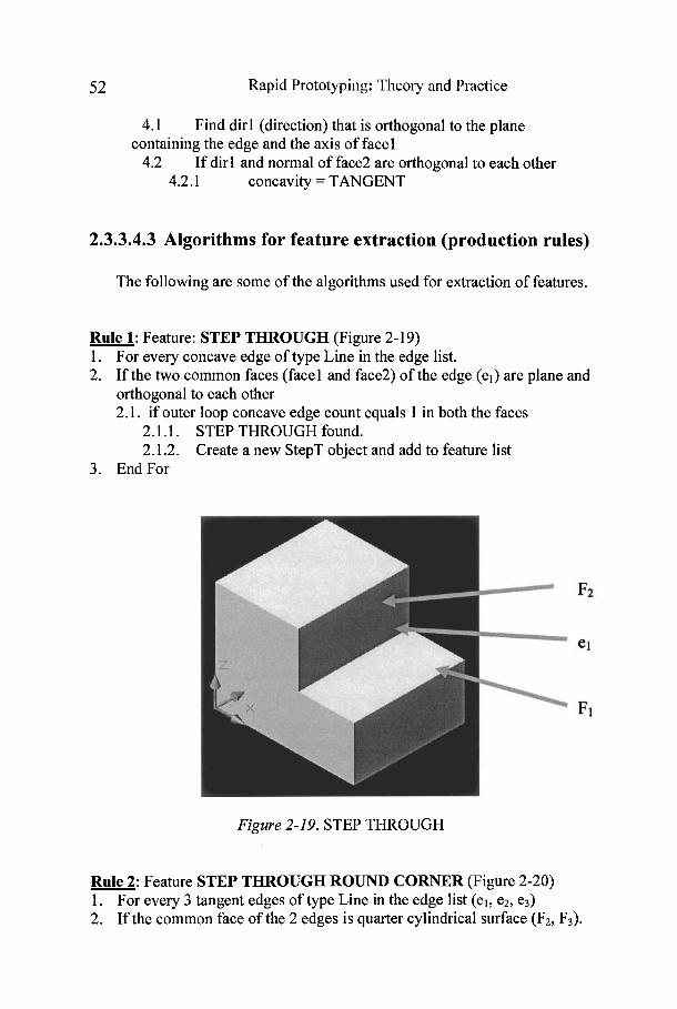
Rule 1: Feature: STEP THROUGH (Figure 2-19) 1. For every concave edge of type Line in the edge list. 2. If the two common faces (facel and face2) of the edge (el) are plane and
orthogonal to each other 2.1. if outer loop concave edge count equals 1 in both the faces
2.1.1. STEP THROUGH found. 2.1.2. Create a new StepT object and add to feature list
3. End For
Figure 2-19. STEP THROUGH
Rule 2: Feature STEP THROUGH ROUND CORNER (Figure 2-20) 1. For every 3 tangent edges of type Line in the edge list (el, e2, e3) 2. If the common face of the 2 edges is quarter cylindrical surface (F2, F3).

Rapid Prototyping: Theory and Practice 5 3
2.1. The other two faces (F1, F4) coqnected to edges are perpendicular to each other.
2.1.1. If concave edge count of the outer loops of the four faces equals 0 each.
2.1.1.1. STEP THROUGH ROUND CORNER found 2.1.1.2. Create a new StepT-RC object and add to feature list.
3. End For
Figure 2-20. STEP THROUGH ROUND CORNER
In general, the following steps are the proposed methodology for feature's extraction and classifications: Step 1: Extract the geometry and topology entities for the designed object
model from IGES file: (a) Identify vertices, edges, faces, loops of the object.
Step 2: Extract topology entities in each basic surface and Identify its type: (a) Identify the total number of loops in each surface. (b) Identify the basic surface due to total number of loops. (c) Classify the loops into different types (concave, convex, and
hybrid).
Step 3: Test the feature's existence in the basic surface based on loops.
Step 4: Identify feature type: (a) Identify Exterior Form Features (FFe,,ior) by searching for
hybrid loop. (b) Identify Interior Convex Form Features (FFinteri0r) by searching

54 Rapid Prototyping: Theory and Practice
for convex loop. (c) Identify Interior Concave Form Features (FFinterior) by searching
for concave loop.
Step 5: Identify the detailed features and extract the related feature geometry parameters: (a) Identify feature's details (number of surfaces, surface type). (b) Identify the parameters of each feature (length (L), width (W),
height (H), radius (R). (c) Identify the relative location of each feature due to the origin
coordinates of the object.
Step 6: Identify the detailed machining information for each feature and the designed part: (a) Identify the operation sequence of the designed part. (b) Identify the operation type, the machine, and the cutting tool for
each feature. (c) Identify the tool approachlmachining direction for each feature. (d) Identify the removed machining volume for each feature.
2.4. An Illustrative Example
The designed object as shown in Figure 2-21 consists of five solid primitives which are four blocks (prismatic raw material, slot, blind step, and through pocket) and one cylinder (through hole). After the part is created, its IGES file will be generated. By applying the proposed methodology, the results are shown in Tables 2-3 to 2-8.
Feature 3$., Feature 5 Feature 4
Feature 1 Feature 2 Figure 2-21.An Illustrative Example
Step 1: Extract the geometry and topology entities for the designed object

Rapid Prototyping: Theory and Practice 55
model from IGES file.
Step 2: Extract topology entities in each basic surface and Identify its type.
Table 2-3. Extraction of Vertices
NO. vertex Coordinates NO. vertex Coordinates ID (X,Y,Z) ID (X,Y,Z)
Table 2-4. Extraction of Edges
Edge Edge Coordinates Length Concavity ID Type Starting Terminate
Point Point Center h d i u s
[I] Line [I] [21 16 Tangent
[2] Cir. Arc [3] 111 (15,8,16) 4
[3] Line [41 P I 16 Tangent [4] Cir. Arc [2] [41 (1v-40) 4

56 Rapid Prototyping: Theory and Practice
Table 2-4. Extraction of Edges (cont.)
Line Line Line Line Line Line Line
Line Line Line Line Line
Cir. Arc Cir. Arc
Line Line Line Line Line Line
Line Line Line Line Line Line Line Line Line Line Line Line
Concave Concave Concave Concave Concave Convex Concave Concave Convex Concave Convex Convex
Convex Concave Concave Concave Concave Convex Convex Convex Convex Convex Convex Convex Convex Concave Convex Concave Convex Convex Convex

Rapid Prototyping: Theory and Practice 5 7
Table 2-4. Extraction of Edges (cont.)
[39] Line ~291 [241 5 Convex [40] Line Pol [291 16 Convex [41] Line [23 1 [3 01 5 Convex [42] Line ~291 1181 18 Convex [431 Line 1311 [281 2 Convex [44] Line [311 [321 16 Convex
[45] Line P O I WI 30 Convex
[46] Line [271 [331 2 Convex
[47] Line 1331 [311 16 Convex
[48] Line [221 [3 01 23 Convex
[49] Line [321 [34l 16 Convex
[ ~ O I Line 1341 P11 3 o Convex
[51] Line [331 1341 16 Convex
Table 2-5. Extraction of Loom
Loop Loop Loop Face ID Type Category ID Edge ID
External External External External External External External External External External External External External External
External
Concave Concave Hybrid Hybrid Hybrid Hybrid
Concave Hybrid Hybrid Hybrid Convex Hybrid Hybrid Hybrid
Convex

58 Rapid Prototyping: Thcory and Practicc
Table 2-5. Extraction of Loops (Cont.)
External External
Internal
Internal
External
Internal External
External
Convex
Convex
Convex
Concave Convex
Concave
Convex
Convex
Table 2-6. Extraction of Faces
Face Surface Normal ID Type Vector
Number Loop Concavity of Loops ID
[I] Surface of revolution Concave Plane Surface
12] (parameterized) (0,0,1) Concave
Plane Surface 13] (parameterized) (0,1,0) Concave
Plane Surface 14] (parameterized) (0,O-1) Concave
'lane Surface 0 , - 1 o Concave (parameterized) Plane Surface
[61 (parameterized) (-100) Concave
[7] Surface of revolution Concave Plane Surface
19] (parameterized) (1,0,0) Concave
Plane Surface [' O1 (parameterized) (0-10) Concave
Plane Surface [I (parameterized)
(00-1) Concave
Plane Surface 21 (parameterized) (0,0,1) Concave
Plane Surface [I3] (parameterized)
(00-1) Concave
1141 Plane Surface (-100) Concave (parameterized)
Rapid Prototyping: Theory and Practice 5 9
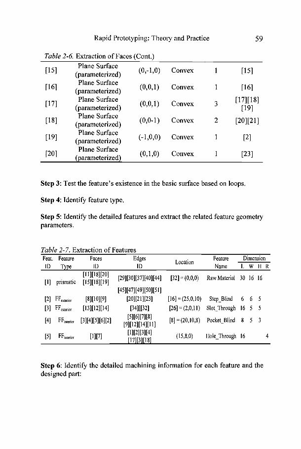
Table 2-6. Extraction of Faces (Cont.) Plane Surface
51 (parameterized) (0-10) Convex 1 1151
Plane Surface [ ' 61 (parameterized) (0,0,1) Convex 1 [I61
Plane Surface (0,0,1) Convex 3 [171[181 [ ' 71 (parameterized) 1191 Plane Surface
(parameterized) (0,O-I) Convex 2 [201[211
Plane Surface [' 91 (parameterized) (-10,O) Convex I
P O I Plane Surface
(parameterized) (o,I,o) Convex 1 [231
Step 3: Test the feature's existence in the basic surface based on loops.
Step 4: Identify feature type.
Step 5: Identify the detailed features and extract the related feature geometry parameters.
Table 2-7. Extraction of Features Feat. Feature Faces Edges Feature Dimension
ID ID Location
ID Type Name L W H R
81[201 [29][30][37][40][44] [32] = (0,O.O) Raw Material 30 16 16 [l] prismatic [15][18][19]
[4~1[471[491[~01[~ 11 [21 FFexte"or [81[101[91 [20][21][23] [16] = (25,0,10) Step-Blind 6 6 5
[31 FFex,"or [131[121[141 [341[[321 [26] = (2,0,11) Slot-Through 16 5 5 [51[61[71[81 [8]=(20,10,8) Pocket-Blind 8 5 3 P I FFin,or [31[4l[51[6IPl [91[12l[l41[lll
[5I FFinterior [1I[7I [11[21[31[41 [17][3][18]
(15,8,0) Hole-Through 16 4
Step 6: Identifjr the detailed machining information for each feature and the designed part:
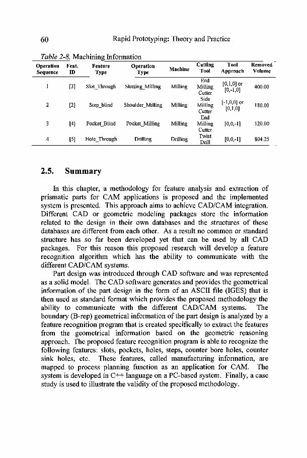
60 Rapid Prototyping: Theory and Practicc
Table 2-8. Machining Information Operation Feat. Feature Operation Cutting Tool Removed Seauence ID Tvoe Tvoe Machine Tool Approach Volume
End 1 [3] Slot-Through Slotting-Milling Milling Milling [0'1'01 Or 400.00
Cutter [0,-1,01 Side
2 [2] Step-blind Shoulder-Milling Milling Milling [-1'0'01 Or 180.00 Cutter [0,1,01 End
3 [4] Pocket-Blind Pocket-Milling Milling Milling [0,0,-11 120.00 Cutter
4 [5] Hole-Through Drilling Twist Drilling Drill [0,0,-11 804.25
2.5. Summary
In this chapter, a methodology for feature analysis and extraction of prismatic parts for CAM applications is proposed and the implemented system is presented. This approach aims to achieve CADICAM integration. Different CAD or geometric modeling packages store the information related to the design in their own databases and the structures of these databases are different from each other. As a result no common or standard structure has so far been developed yet that can be used by all CAD packages. For this reason this proposed research will develop a feature recognition algorithm which has the ability to communicate with the different CADICAM systems.
'Part design was introduced through CAD software and was represented as a solid model. The CAD software generates and provides the geometrical information of the part design in the form of an ASCII file (IGES) that is then used as standard format which provides the proposed methodology the ability to communicate with the different CADICAM systems. The boundary (B-rep) geometrical information of the part design is analyzed by a feature recognition program that is created specifically to extract the features from the geometrical information based on the geometric reasoning approach. The proposed feature recognition program is able to recognize the following features: slots, pockets, holes, steps, counter bore holes, counter sink holes, etc. These features, called manufacturing information, are mapped to process planning function as an application for CAM. The system is developed in C++ language on a PC-based system. Finally, a case study is used to illustrate the validity of the proposed methodology.

Rapid Prototyping: Theory and Practice 6 1
References
N. Ahmad and A. Haque, Manufacturing Feature Recognition of Parts Using DXF Files, Fourth International conference on Mechanical Engineering, Dhaka, Bangladesh, 1(1), 1 1 1-1 15 (200 1). M.P. Bhandarkar, B. Downie, M. Hardwick, and R. Nagi, Migrating from IGES to STEP: One to One Translation of IGES Drawing to STEP Drafting Data, Computers in Industry, 41(3), 261-277 (2000). M.W. Fu, S.K. Ong, W.F. Lu, I.B.H. Lee and A.Y.C. Nee, An Approach to Identify Design and Manufacturing Features from A Data Exchanged Part Model, Computer Aided Design, 35(1), 979-993 (2003). C. Hoffmann, and J. Rossignac, A Road Map to Solid Modeling, IEEE Transactions on visualization and Computer graphics, 2(1), 136-149 (1996). J. Hwang, Rule-Based Feature Recognition: Concepts, Primitives and Implementation, Thesis, Arizona State University (1988). C-H. Liu, D-B. Perng, and Z. Chen, Automatic form Feature Recognition and 3D part Recognition from 2D CAD Data, Computer and Industrial Engineering, 14(4), 689-707 (1994). S. Liu, M. Gonzalez and J. Chen, Development of An Automatic Part Feature Extraction and Classification System Taking CAD Data as Input, Computers in Industry, 29(1), 137-150 (1996). X. Ma, G. Zhang, S. Liu, and X. Wang, Measuring Information Integration Model for CADICMM, Chinese Journal of Mechanical Engineering, 16(1), 59-61 (2003). S. Mansour, Automatic Generation of Part Programs foe Milling Sculptured Surfaces, Journal of Materials Processing Technology, 127(1), 3 1-39 (2002).
10. D. Natekar, X. Zhang, and G. Subbarayan, Constructive Solid Analysis: A Hierarchal, Geometry-Based Meshless Analysis Procedure for Integrated Design and Analysis, Computer Aided Design, 36(5), 473-486 (2004).
11. A. Reqicha and H. Voelcker, Solid Modeling: A Historical Summary and Contemporary Assessment, IEEE Computer Graphics and Applications, 2(2) 9-24 (1982).
12. O.W. Salomons, Review of Research in Feature Based Design, Journal of Manufacturing Systems, 12(2), 1 13-132 (1 993).
13. R. Sharma and J. Gao, Implementation of STEP Application Protocol 224 in An Automated Manufacturing Planning System,

Rapid Prototyping: Theory and Practice
Proceedings of the Institution of Mechanical Engineers, Part B: Journal of Engineering Manufacture, 216(1), 1277- 1289 (2002).
14. S. Somashekar and W. Michael, an Overview of Automatic Feature Recognition Techniques for Computer-Aided Process Planning, Computers in Industry, 26(1) 1-2 1 (1 995).
15. V. Sundaarajan and P.K. Wright, Volumetric Feature Recognition For Machining Components With Freeform Surfaces, Computer Aided Design, 36(1), 11-25 (2004).
16. B. G. William, Initial Graphics Exchange Specification IGES 5.3, ANS US PROIIPO-100 (1996).
17. I. Zeid, CAD/CAM Theory and Practice (McGraw-Hill, Inc., 1991).

http://www.springer.com/978-0-387-23290-4