CHAPTER 2 GENERAL DESCRIPTION - cgwic.comcgwic.com/LaunchServices/Download/manual/Chapter 2 General...
26
LM-3A Series Launch Vehicle User’s Manual Issue 2011 2-1 CHAPTER 2 GENERAL DESCRIPTION 2.1 Summary The China Academy of Launch Vehicle Technology (CALT) started to develop the LM-3A Series launch vehicles in 1986, and they are three-stage liquid propellant launch vehicles used mainly for Geostationary Transfer Orbit (GTO) missions. LM-3A Series launch vehicles include the LM-3A, LM-3B, LM-3B Enhanced (LM-3BE) and LM-3C. The configuration of LM-3A Series launch vehicles is shown in Figure 2-1. The GTO capability of LM-3A is 2,600 kg. The LM-3B is a three-stage launch vehicle, which utilizes the proven LM-3A as its core stage and has been upgraded by the addition of four liquid strap-on boosters to the first stage. The second stage tanks were also increased in volume, which increased the GTO capability up to 5,100 kg for the LM-3B version. The LM-3BE is based on the LM-3B but has a lengthened first stage and boosters, which increases the GTO launch capability up to 5,500 kg. The LM-3C is a three-stage launch vehicle but with two liquid strap-on boosters. The LM-3C variant is capable of delivering a satellite with the mass of 3,800 kg into GTO. The LM-3C and LM-3B variants were developed in parallel using the same modular design as the LM-3A. The LM-3C uses the same SC/LV interface and payload fairing as is used by the LM-3B. All the LM-3A Series launch vehicles are flight proven.
Transcript of CHAPTER 2 GENERAL DESCRIPTION - cgwic.comcgwic.com/LaunchServices/Download/manual/Chapter 2 General...

LM-3A Series Launch Vehicle User’s Manual
Issue 2011 2-1
CHAPTER 2 GENERAL DESCRIPTION
2.1 Summary
The China Academy of Launch Vehicle Technology (CALT) started to develop the LM-3A
Series launch vehicles in 1986, and they are three-stage liquid propellant launch vehicles
used mainly for Geostationary Transfer Orbit (GTO) missions. LM-3A Series launch vehicles
include the LM-3A, LM-3B, LM-3B Enhanced (LM-3BE) and LM-3C. The configuration of
LM-3A Series launch vehicles is shown in Figure 2-1. The GTO capability of LM-3A is 2,600
kg.
The LM-3B is a three-stage launch vehicle, which utilizes the proven LM-3A as its core stage
and has been upgraded by the addition of four liquid strap-on boosters to the first stage. The
second stage tanks were also increased in volume, which increased the GTO capability up
to 5,100 kg for the LM-3B version.
The LM-3BE is based on the LM-3B but has a lengthened first stage and boosters, which
increases the GTO launch capability up to 5,500 kg.
The LM-3C is a three-stage launch vehicle but with two liquid strap-on boosters. The LM-3C
variant is capable of delivering a satellite with the mass of 3,800 kg into GTO. The LM-3C
and LM-3B variants were developed in parallel using the same modular design as the
LM-3A. The LM-3C uses the same SC/LV interface and payload fairing as is used by the
LM-3B.
All the LM-3A Series launch vehicles are flight proven.
LM-3A Series Launch Vehicle User’s Manual
Issue 2011 2-2
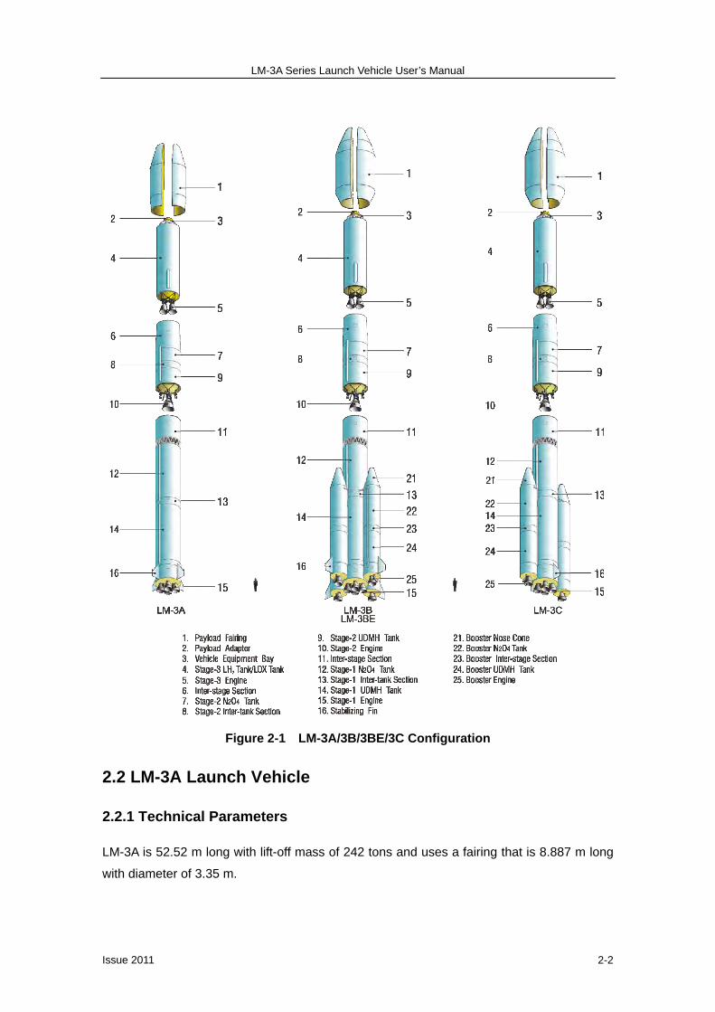
Figure 2-1 LM-3A/3B/3BE/3C Configuration
2.2 LM-3A Launch Vehicle
2.2.1 Technical Parameters
LM-3A is 52.52 m long with lift-off mass of 242 tons and uses a fairing that is 8.887 m long
with diameter of 3.35 m.

LM-3A Series Launch Vehicle User’s Manual
Issue 2011 2-3
Figure 2-2 LM-3A Launch Vehicle

LM-3A Series Launch Vehicle User’s Manual
Issue 2011 2-4
Technical Parameters of the First Stage:
Length 23.272 m Diameter 3.35 m Propellant N2O4 / UDMH Mass of Propellant 171,800 kg Engine YF-21C Ground Thrust 2,961.6 kN Ground Specific Impulse 2,556.5 N·s/kg
Technical Parameters of the Second Stage:
Length 11.276 m Diameter 3.35 m Propellant N2O4 / UDMH Mass of Propellant 32,600 kg Engine YF-24E Thrust ( in vacuum) Main Engine: 742 kN Vernier Engine: 47.1 kN Specific Impulse (in vacuum) Main Engine: 2,922.57 N·s/kg Vernier Engine: 2,910.5 N·s/kg
Technical Parameters of the Third Stage:
Length 12.375 m Diameter 3.0 m Propellant LOX / LH2
Mass of Propellant 18,200 kg Engine YF-75 Thrust (at vacuum) 167.17 kN Specific Impulse (in vacuum) 4,295 N·s/kg
2.2.2 LM-3A Description
The LM-3A launch vehicle consists of the following major subsystems: vehicle structure,
propulsion system, control system, measurement system (telemetry system and tracking &
range safety system), propellant management system & reaction control system, propellant
utilization system, separation system and auxiliary system.
Vehicle Structure
The function of the vehicle structure is to withstand the internal and external loads on the
launch vehicle during ground transportation, hoisting and flight, in addition to housing all the
sub-systems. The vehicle structure comprises the first stage, second stage, third stage and
payload fairing.

LM-3A Series Launch Vehicle User’s Manual
Issue 2011 2-5
Figure 2-3 CALT Assembly Area
The first stage includes inter-stage section, oxidizer tank, inter-tank section, fuel tank, rear
transit section, tail section, engine, valves and pipes.
The second stage is comprised of oxidizer tank, inter-tank section, fuel tank, and engine.
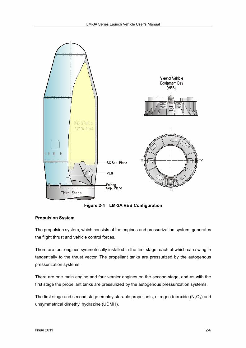
The third stage includes the Payload Adapter (PLA), vehicle equipment bay (VEB),
cryogenic propellant tanks and engine. The PLA mates the satellite with the LM-3A and
transfers the loads between them. The PLA can be one of the international standard
interfaces designated as 937B, 1194 or 1194A. The VEB is a circular structure made of
metal honeycomb and trusses (see Figure 2-4), which is mounted on top of the propellant
tanks. The propellant tank of third stage is thermally insulated with a common bulkhead,
convex upward in the middle. The common bulkhead is thermally insulated with dual-layer
honeycomb vacuum thermal insulation. The tanks are arranged with the liquid hydrogen
(LH2) in the upper tank and liquid oxygen (LOX) in the lower tank.
The payload fairing consists of the dome, forward cone section, cylindrical section, reverse
cone section, and fairing separation mechanisms (see Chapter 4 for details).
LM-3A Series Launch Vehicle User’s Manual
Issue 2011 2-6
Figure 2-4 LM-3A VEB Configuration
Propulsion System
The propulsion system, which consists of the engines and pressurization system, generates
the flight thrust and vehicle control forces.
There are four engines symmetrically installed in the first stage, each of which can swing in
tangentially to the thrust vector. The propellant tanks are pressurized by the autogenous
pressurization systems.
There are one main engine and four vernier engines on the second stage, and as with the
first stage the propellant tanks are pressurized by the autogenous pressurization systems.
The first stage and second stage employ storable propellants, nitrogen tetroxide (N2O4) and
unsymmetrical dimethyl hydrazine (UDMH).
LM-3A Series Launch Vehicle User’s Manual
Issue 2011 2-7
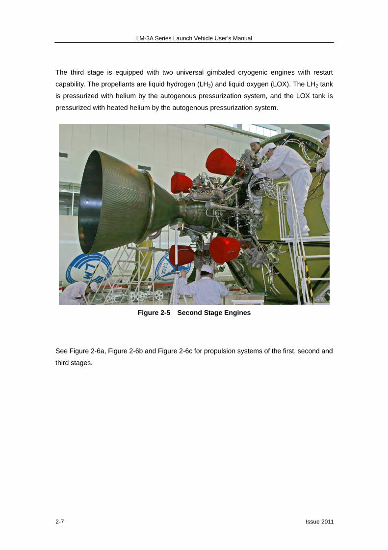
The third stage is equipped with two universal gimbaled cryogenic engines with restart
capability. The propellants are liquid hydrogen (LH2) and liquid oxygen (LOX). The LH2 tank
is pressurized with helium by the autogenous pressurization system, and the LOX tank is
pressurized with heated helium by the autogenous pressurization system.
Figure 2-5 Second Stage Engines
See Figure 2-6a, Figure 2-6b and Figure 2-6c for propulsion systems of the first, second and
third stages.

LM-3A Series Launch Vehicle User’s Manual
Issue 2011 2-8
Figure 2-6a Schematic Diagram of Stage-1 Propulsion System
Figure 2-6b Schematic Diagram of Stage-2 Propulsion System

LM-3A Series Launch Vehicle User’s Manual
Issue 2011 2-9
Figure 2-6c Schematic Diagram of Stage-3 Propulsion System
Control System
The function of control system is to maintain the flight stability, perform the navigation and
guidance functions to deliver the satellite into the predetermined orbit. The control system
uses a four-axis inertial platform and laser IMU, combined with computer-controlled
guidance and digital attitude control. The control system uses advanced digital technologies
and redundancy design to provide enhanced reliability and flexibility for a wide range of
missions for the LM-3A. Figure 2-7a, Figure 2-7b and Figure 2-7c illustrate the schematic
diagrams of the LM-3A Series launch vehicles control system.

LM-3A Series Launch Vehicle User’s Manual
Issue 2011 2-10
Figure 2-7a Schematic Diagram of LM-3A Guidance & Control System
Figure 2-7b Schematic Diagram of LM-3A Attitude Control System
Figure 2-7c Schematic Diagram of LM-3A Guidance System

LM-3A Series Launch Vehicle User’s Manual
Issue 2011 2-11
Measurement System
The measurement system includes the telemetry system and the tracking and range safety
system.
(a) Telemetry System
The functions of telemetry system are to measure and transmit parameters of the launch
vehicle in flight. Some measured data can be processed in real time. The data acquisition
and encoding units in the telemetry system are powered in group based on sensors’ location.
The measurements of the command signals are digitized. The powering and check-up are
performed automatically. The on-board digital converters are intelligent. Totally about 560
parameters are measured in flight. Refer to Figure 2-8 for the diagram of LM-3A Telemetry
System.
Figure 2-8 Schematic Diagram of LM-3A Telemetry System
(b) Tracking and Range Safety System
The tracking and range safety system is used to measure the trajectory data and final
injection parameters, and provide safety assessment information. Self-destruction or
destruction by remote control will be conducted if flight anomaly occurs. See Figure 2-9.

LM-3A Series Launch Vehicle User’s Manual
Issue 2011 2-12
Figure 2-9 Schematic Diagram of LM-3A Tracking & Range Safety System
Propellant Management and Attitude Control System
This system is used for the attitude control and propellant management during the coast
phase of the third stage, final velocity adjustment after engines shutdown and attitude
reorientation prior to satellite separation. It adopts a set of reaction control thrusters fueled
by pressure-fed hydrazine, which can be started for multiple times according to the
command. See Figure 2-10 for the system diagram.
Figure 2-10 LM-3A Propellant Management & Attitude Control System
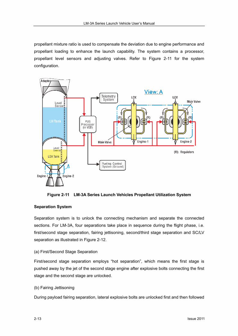
Propellant Utilization System
The propellant utilization system on third stage is to measure in real time the level of
propellants inside the third stage tanks and to adjust the consuming rate of liquid oxygen
(LOX) to achieve the residual propellants in an optimum proportion. The adjustment of
LM-3A Series Launch Vehicle User’s Manual
Issue 2011 2-13
propellant mixture ratio is used to compensate the deviation due to engine performance and
propellant loading to enhance the launch capability. The system contains a processor,
propellant level sensors and adjusting valves. Refer to Figure 2-11 for the system
configuration.
Figure 2-11 LM-3A Series Launch Vehicles Propellant Utilization System
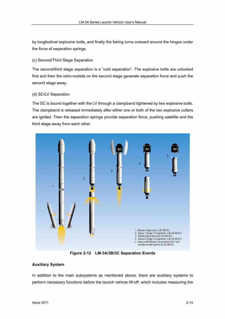
Separation System
Separation system is to unlock the connecting mechanism and separate the connected
sections. For LM-3A, four separations take place in sequence during the flight phase, i.e.
first/second stage separation, fairing jettisoning, second/third stage separation and SC/LV
separation as illustrated in Figure 2-12.
(a) First/Second Stage Separation
First/second stage separation employs “hot separation”, which means the first stage is
pushed away by the jet of the second stage engine after explosive bolts connecting the first
stage and the second stage are unlocked.
(b) Fairing Jettisoning
During payload fairing separation, lateral explosive bolts are unlocked first and then followed
LM-3A Series Launch Vehicle User’s Manual
Issue 2011 2-14
by longitudinal explosive bolts, and finally the fairing turns outward around the hinges under
the force of separation springs.
(c) Second/Third Stage Separation
The second/third stage separation is a “cold separation”. The explosive bolts are unlocked
first and then the retro-rockets on the second stage generate separation force and push the
second stage away.
(d) SC/LV Separation
The SC is bound together with the LV through a clampband tightened by two explosive bolts.
The clampband is released immediately after either one or both of the two explosive cutters
are ignited. Then the separation springs provide separation force, pushing satellite and the
third stage away from each other.
Figure 2-12 LM-3A/3B/3C Separation Events
Auxiliary System
In addition to the main subsystems as mentioned above, there are auxiliary systems to
perform necessary functions before the launch vehicle lift-off, which includes measuring the

LM-3A Series Launch Vehicle User’s Manual
Issue 2011 2-15
propellant level and temperature, air-conditioning, water-proofing and dehumidifying for
payload fairing.
2.3 LM-3B and LM-3BE Launch Vehicles
2.3.1 Technical Parameters
The total lift-off mass for the LM-3B and LM-3BE is 426 tons and 456 tons respectively. The
total length is 54.838 m ~ 57.056 m depending on the type of payload fairing to be used and
fairing encapsulation method selected.
Figure 2-13 LM-3B Launch Vehicle
There are four types of payload fairing available for launch services with the nominal
diameter of 3.7 m (for dual launch), 4.0 m and 4.2 m respectively. The option selected is
dependent on whether the fairing is encapsulated on the pad or in BS3 (SC Hazardous
Operation Building). The two encapsulation ways are as follows:
Encapsulation-on-Pad
When the satellite is encapsulated on the pad, the satellite and fairing are transported to
launch pad separately; then the fairing is encapsulated following the mate of satellite to the
launch vehicle.
LM-3A Series Launch Vehicle User’s Manual
Issue 2011 2-16
Encapsulation-in-BS3
When the satellite is encapsulated in BS3, the satellite is mated to the Payload Adapter
(PLA) and encapsulated in the fairing in BS3. The encapsulated satellite is shipped to the
launch pad in the fairing and the complete assembly is mated to the launch vehicle on the
launch pad.
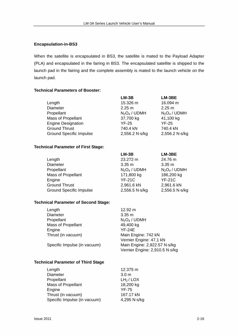
Technical Parameters of Booster:
LM-3B LM-3BE Length 15.326 m 16.094 m Diameter 2.25 m 2.25 m Propellant N2O4 / UDMH N2O4 / UDMH Mass of Propellant 37,700 kg 41,100 kg Engine Designation YF-25 YF-25 Ground Thrust 740.4 kN 740.4 kN Ground Specific Impulse 2,556.2 N·s/kg 2,556.2 N·s/kg
Technical Parameter of First Stage:
LM-3B LM-3BE Length 23.272 m 24.76 m Diameter 3.35 m 3.35 m Propellant N2O4 / UDMH N2O4 / UDMH Mass of Propellant 171,800 kg 186,200 kg Engine YF-21C YF-21C Ground Thrust 2,961.6 kN 2,961.6 kN Ground Specific Impulse 2,556.5 N·s/kg 2,556.5 N·s/kg
Technical Parameter of Second Stage:
Length 12.92 m Diameter 3.35 m Propellant N2O4 / UDMH Mass of Propellant 49,400 kg Engine YF-24E Thrust (in vacuum) Main Engine: 742 kN Vernier Engine: 47.1 kN Specific Impulse (in vacuum) Main Engine: 2,922.57 N·s/kg Vernier Engine: 2,910.5 N·s/kg
Technical Parameter of Third Stage
Length 12.375 m Diameter 3.0 m Propellant LH2 / LOX
Mass of Propellant 18,200 kg Engine YF-75 Thrust (in vacuum) 167.17 kN Specific Impulse (in vacuum) 4,295 N·s/kg

LM-3A Series Launch Vehicle User’s Manual
Issue 2011 2-17
2.3.2 LM-3B and LM-3BE Description
The LM-3B and LM-3BE launch vehicles are comprised of the vehicle structure, propulsion
system, control system, measurement system (telemetry system and tracking & range
safety system), propellant management and reaction control system, propellant utilization
system, separation system and auxiliary system, etc.
Vehicle Structure
The vehicle structure consists of the core stage and boosters, with the core stage being
similar to that of LM-3A but with an enhanced tank structure to meet the flight load
requirements of LM-3B. The tanks of the second stage have been extended by a total of
1.65 m to allow more propellants to be loaded (See Figure 2-1).
The booster consists of nose, oxidizer tank, inter-tank section, fuel tank, rear transit section,
tail section, fins, engine, valves and pipes, etc.
The third stage includes the Payload Adapter (PLA), vehicle equipment bay (VEB),
cryogenic propellant tanks and engines. The PLA mates the satellite to LM-3B and bears the
mechanical loads. The PLA can be one of the international standard interfaces designated
as 937B, 1194 or 1194A. The satellite can be encapsulated on the pad or in BS3 (See Figure
2-14 and Figure 2-15).
The payload fairings consist of the dome, bi-conic section, cylindrical section, and reverse
cone section and separation mechanisms. See Chapter 4 for details.

LM-3A Series Launch Vehicle User’s Manual
Issue 2011 2-18
Figure 2-14 LM-3B & LM-3C Fairing for Encapsulation-on-Pad
LM-3A Series Launch Vehicle User’s Manual
Issue 2011 2-19
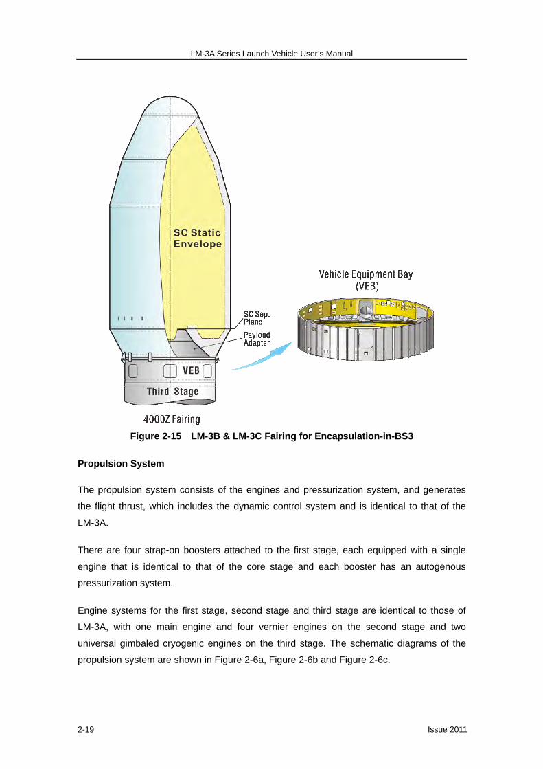
Figure 2-15 LM-3B & LM-3C Fairing for Encapsulation-in-BS3
Propulsion System
The propulsion system consists of the engines and pressurization system, and generates
the flight thrust, which includes the dynamic control system and is identical to that of the
LM-3A.
There are four strap-on boosters attached to the first stage, each equipped with a single
engine that is identical to that of the core stage and each booster has an autogenous
pressurization system.
Engine systems for the first stage, second stage and third stage are identical to those of
LM-3A, with one main engine and four vernier engines on the second stage and two
universal gimbaled cryogenic engines on the third stage. The schematic diagrams of the
propulsion system are shown in Figure 2-6a, Figure 2-6b and Figure 2-6c.

LM-3A Series Launch Vehicle User’s Manual
Issue 2011 2-20
Control System
The function and composition of the Control System is basically similar to that of the LM-3A,
except that an additional control circuit has been added to control the engine ignition,
shutdown and separation of the strap-on boosters. See Figure 2-7a, Figure 2-7b and Figure
2-7c.
Measurement System
(a) Telemetry System
The telemetry system is basically similar to that of LM-3A with telemetry circuit added to
measure parameters of the boosters. There are altogether about 800 parameters measured
in flight. See Figure 2-8.
(b) Tracking and Range Safety System
The Tracking and Range Safety System has the similar function and composition to that of
LM-3A. See Figure 2-9.
Propellant Management and Attitude Control System during Coast Flight
There is a Propellant Management and Attitude Control System on the third stage. The
system has the same function and composition with those of LM-3A. To meet the
requirements of attitude control of LM-3B, two small reaction nozzles each with thrust of 40N
are added for pitch and yaw. The thrust of propellant settling nozzle is increased from 40N in
LM-3A to 45N in LM-3B /3C due to the mass increase during the coast flight phase of
LM-3B/3C. See Figure 2-16.
Figure 2-16 LM-3B/3BE/3C Propellant Management & Attitude Control System

LM-3A Series Launch Vehicle User’s Manual
Issue 2011 2-21
Separation Systems
There are five separation actions during the flight of LM-3B: booster separation, first/second
stage separation, fairing jettisoning, second/third stage separation and SC/LV separation as
illustrated in Figure 2-12.
(a) Booster Separation.
The boosters are “thrown-away” upon separation. Before separation, boosters are mounted
to the core stage through three pairs of explosive bolts at the front section and a separation
nut at the rear section. Four small separation nozzles generate outward separation force to
push the boosters away from the first stage following the simultaneous unlocking of the
explosive bolts and the separation nut.
(b) First/Second Stage Separation
The same as that of LM-3A.
(c) Fairing Jettisoning
During the payload fairing separation, the lateral explosive bolts unlock first and then the
longitudinal detonation cord and explosive bolts unlock. The fairing turns outward around
the hinges under the force of separation springs.
(d) Second/Third Stage Separation
The same as that of LM-3A.
(e) Satellite Separation System
The same as that of LM-3A.
Propellant Utilization System and Auxiliary System
The propellant utilization system is identical to that of LM-3A. See Figure 2-11. The auxiliary
system is same as that of LM-3A.
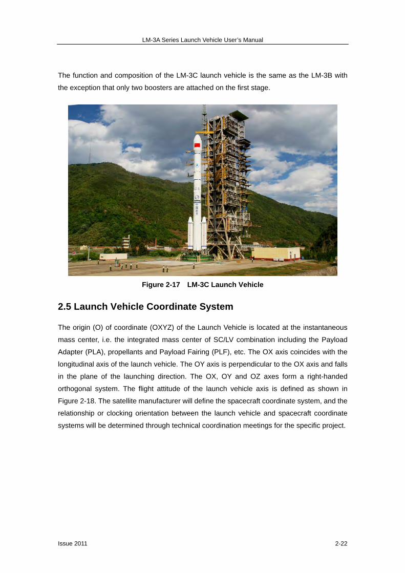
2.4 LM-3C Launch Vehicle
Total lift-off mass of the LM-3C (Figure 2-17) is approximately 345 tons and its overall length
is 54.838 m with a fairing of 4 m in diameter (Encapsulation-on-Pad). The fairings available
and their encapsulation methods are the same as that of LM-3B. See Section 2.3 covering
the LM-3B for details.
LM-3A Series Launch Vehicle User’s Manual
Issue 2011 2-22
The function and composition of the LM-3C launch vehicle is the same as the LM-3B with
the exception that only two boosters are attached on the first stage.
Figure 2-17 LM-3C Launch Vehicle
2.5 Launch Vehicle Coordinate System
The origin (O) of coordinate (OXYZ) of the Launch Vehicle is located at the instantaneous
mass center, i.e. the integrated mass center of SC/LV combination including the Payload
Adapter (PLA), propellants and Payload Fairing (PLF), etc. The OX axis coincides with the
longitudinal axis of the launch vehicle. The OY axis is perpendicular to the OX axis and falls
in the plane of the launching direction. The OX, OY and OZ axes form a right-handed
orthogonal system. The flight attitude of the launch vehicle axis is defined as shown in
Figure 2-18. The satellite manufacturer will define the spacecraft coordinate system, and the
relationship or clocking orientation between the launch vehicle and spacecraft coordinate
systems will be determined through technical coordination meetings for the specific project.

LM-3A Series Launch Vehicle User’s Manual
Issue 2011 2-23
Figure 2-18 Coordinate System of LM-3A/3B/3BE/3C
2.6 Launch Missions of LM-3A Series Launch Vehicles
LM-3A Series launch vehicles are primarily used for GTO missions, although LEO and SSO
missions can also be conducted if required by customers.
GTO Missions
The main mission for the LM-3A Series launch vehicles is to deliver the satellite into
Geostationary Transfer orbit (GTO). The transfer of the satellite from GTO to the
Geostationary Earth Orbit (GEO) will be conducted by the engine carried on the satellite.
GTO refers to an elliptical orbit with an apogee altitude equal or even higher than the altitude
LM-3A Series Launch Vehicle User’s Manual
Issue 2011 2-24
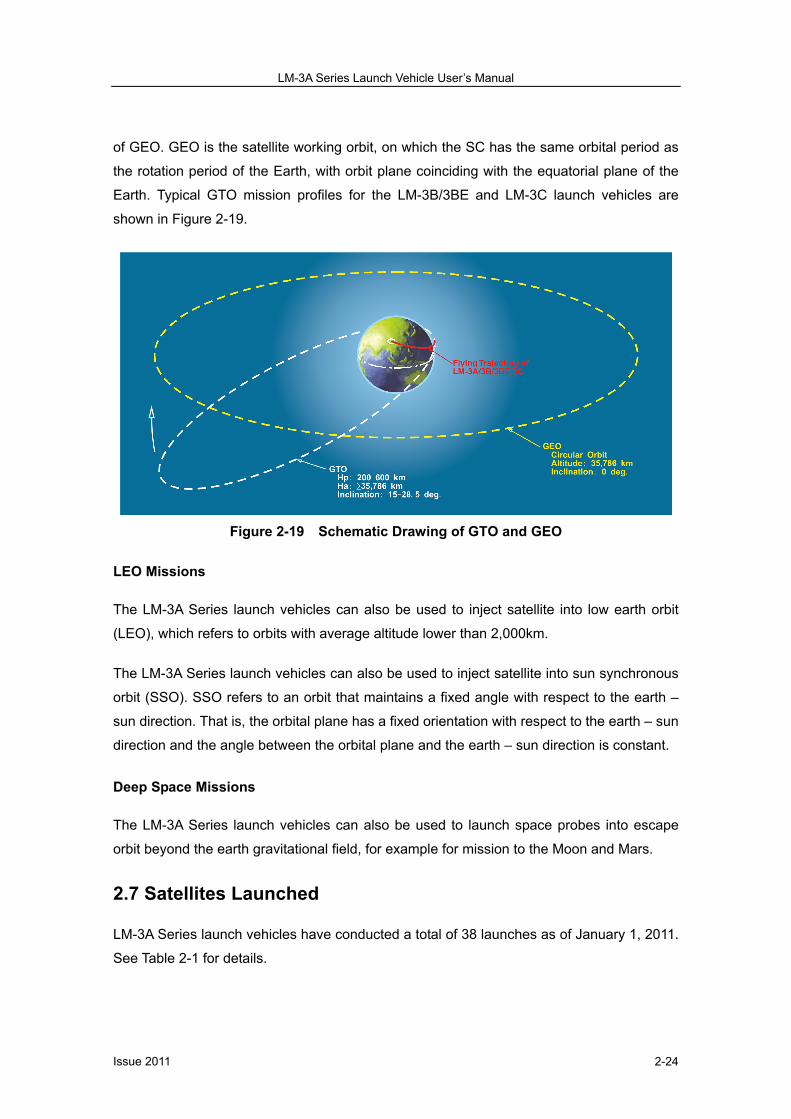
of GEO. GEO is the satellite working orbit, on which the SC has the same orbital period as
the rotation period of the Earth, with orbit plane coinciding with the equatorial plane of the
Earth. Typical GTO mission profiles for the LM-3B/3BE and LM-3C launch vehicles are
shown in Figure 2-19.
Figure 2-19 Schematic Drawing of GTO and GEO
LEO Missions
The LM-3A Series launch vehicles can also be used to inject satellite into low earth orbit
(LEO), which refers to orbits with average altitude lower than 2,000km.
The LM-3A Series launch vehicles can also be used to inject satellite into sun synchronous
orbit (SSO). SSO refers to an orbit that maintains a fixed angle with respect to the earth –
sun direction. That is, the orbital plane has a fixed orientation with respect to the earth – sun
direction and the angle between the orbital plane and the earth – sun direction is constant.
Deep Space Missions
The LM-3A Series launch vehicles can also be used to launch space probes into escape
orbit beyond the earth gravitational field, for example for mission to the Moon and Mars.
2.7 Satellites Launched
LM-3A Series launch vehicles have conducted a total of 38 launches as of January 1, 2011.
See Table 2-1 for details.

LM-3A Series Launch Vehicle User’s Manual
Issue 2011 2-25
Table 2-1 SC launched by LM-3A Series LV (As of January 1, 2011) Designed Orbit LV SC
Manufacture SC Name Launch Date
i (deg) Hp (km) Ha (km) SC Mass
(Kg)
F01 CAST/CALT SJ-4/KF-1 1994.02.08 28.5 200 36,311 396/1,342
F02 CAST ChinaSat-5 1994.11.30 28.5 200 36,185 2,232
F03 CAST ChinaSat-6 1997.05.12 28.5 200 36,065 2,267
F04 CAST ChinaSat-22 2000.01.26 25.0 200 41,991 2,320
F05 CAST BD-1A 2000.10.31 25.0 200 41,991 2,315
F06 CAST BD-1B 2000.12.21 25.0 200 41,991 2,311
F07 CAST BD-1C 2003.05.25 25.0 200 41,991 2,325
F08 CAST ChinaSat-20 2003.11.15 25.0 200 41,991 2,307
F09 SAST FY-2C 2004.10.19 27.1 280 36,056 1,400
F10 CAST ChinaSat-22A 2006.09.13 25.0 200 41,991 2,330
F11 SAST FY-2D 2006.12.08 24.9 200 36,407 1,390
F12 CAST BD-1D 2007.02.03 25.0 200 41,991 2,299
F13 CAST Compass-01 2007.04.14 55.0 200 21,650 2,320
F14 CAST SinoSat-3 2007.06.01 25.0 200 41,991 2,320
F15 CAST CE-1 2007.10.24 31.0 200 51,000 2,352
F16 SAST FY-2E 2008.12.23 24.1 200 35,700 1,390
F17 CAST Compass-05 2010.08.01 55.0 200 35,991 2,300
F18 CAST ChinaSat-20A 2010.11.25 25.0 200 41,991 2,325
LM
-3A
F19 CAST Compass-07 2010.12.18 55.0 200 35,991 2,300
F01 SS/Loral Intelsat-708 1996.02.15 24.5 200 35,786 4,594
F02 SS/Loral MABUHAY 1997.08.20 24.5 200 47,924 3,775
F03 SS/Loral APSTAR-2R 1997.10.17 24.5 200 47,924 3,746
F04 Lockheed Martin ChinaStar-1 1998.05.30 24.5 200 85,000 2,917
F05 Aerospatial SinoSat-1 1998.07.18 19.0 600 35,786 2,832
F06 Alcatel Space APSTAR-VI 2005.04.12 26.0 200 50,000 4,576
F07 CAST SinoSat-2 2006.10.29 28.5 200 35,786 5,107
F08* CAST NigComSat-1 2007.05.14 25.2 200 41,991 5,086
F09 TAS ChinaSat-6B 2007.07.05 24.3 200 50,289 4,516
F10 TAS ChinaSat-9 2008.06.09 24.2 200 50,289 4,466
F11* CAST VeneSat-1 2008.10.30 24.8 200 41,991 5,050
F12 TAS Palapa-D 2009.08.31 21.2 200 50,291 4,100
LM
-3B
/ L
M-3
BE
(m
arke
d w
ith
*)
F13* CAST SinoSat-6 2010.09.06 25.2 200 41,991 5,100
F01 CAST TL-1 2008.04.25 18.0 200 41,991 2,475
F02 CAST Compass-02 2009.04.15 20.5 200 35,974 3,060
F03 CAST Compass-03 2010.01.17 20.5 200 35,974 3,060
F04 CAST Compass-04 2010.06.02 20.5 200 35,974 3,060
F05 CAST CE-2 2010.10.01 28.5 200 364,160 2,480
LM
-3C
F06 CAST Compass-06 2010.11.01 20.5 200 35,974 3,060
LM-3A Series Launch Vehicle User’s Manual
Issue 2011 2-26
2.8 Future Enhancements for LM-3A Series Launch Vehicles
The following enhancements are being planned for the LM-3A Series launch vehicles:
a) To further improve the reliability and robustness of LM-3A Series launch vehicles.
b) To study the feasibility to improve the launch capability of LM-3B to 6 tons for the
standard GTO mission.
c) To introduce a newly developed upper stage, so that payloads can be launched into
10,000~20,000 km circular orbit or directly injected into GEO. The new upper stage has
the capability to readjust attitude and reorient so that multiple satellites can be launched
with one launch vehicle. Launch vehicles for deep space exploration will be developed
on the basis of LM-3A Series launch vehicles, which are the basic carriers for space
exploration flight in China to send the payloads into transfer orbit to the Moon or Mars.
d) Please refer to our web site for announcements and updates.