
Chapter 18 Wind Turbine Tribology - Academic Commons
48
Chapter 18 Wind Turbine Tribology Elon J. Terrell, William M. Needelman and Jonathan P. Kyle 18.1 Introduction Wind power is of increasing interest in society due to its prospects as an environmentally friendly source of renewable energy. The use of wind turbines to extract electrical energy from wind can be dated back to the late-1800s, with the 12 kW windmill generator by Charles Brush [1], as well as the mid-1900s, with the 1250 kW Smith-Putnam wind turbine. Developments in the wind industry were encouraged by the oil crisis in 1973. Between the early developments of wind turbines and the present day, wind turbine designs have made significant developments in complexity, size, and power capacity (Fig. 18.1). Wind power is now recognized as one of the fastest growing source of energy production (Fig. 18.2), having a worldwide wind power installed capacity exceeding 120 GW [2–4]. The future prospects for wind power installation indicate that growth will continue, as the United States Department of Energy targets 20% wind-based electricity generation, i.e. over 300 GW, by 2030 [5], while TPWind predicts wind energy to account for 12–14% of the total energy production by 2020 and 25% by 2030 [6]. Additionally, China aims for 15% renewable power generation by 2020 [7, 8]. E. J. Terrell (&) J. P. Kyle Mechanical Engineering Department, Columbia University, 500 West 120th Street, New York, NY 10027, USA e-mail: [email protected] J. P. Kyle e-mail: [email protected] W. M. Needelman Donaldson Company, Inc, 8 Hillside Court, Huntington, NY 11743, USA e-mail: [email protected] M. Nosonovsky and B. Bhushan (eds.), Green Tribology, Green Energy and Technology, DOI: 10.1007/978-3-642-23681-5_18, Ó Springer-Verlag Berlin Heidelberg 2012 483
Transcript of Chapter 18 Wind Turbine Tribology - Academic Commons

Chapter 18Wind Turbine Tribology
Elon J. Terrell, William M. Needelman and Jonathan P. Kyle
18.1 Introduction
Wind power is of increasing interest in society due to its prospects as anenvironmentally friendly source of renewable energy. The use of wind turbines toextract electrical energy from wind can be dated back to the late-1800s, with the12 kW windmill generator by Charles Brush [1], as well as the mid-1900s, withthe 1250 kW Smith-Putnam wind turbine. Developments in the wind industrywere encouraged by the oil crisis in 1973. Between the early developments ofwind turbines and the present day, wind turbine designs have made significantdevelopments in complexity, size, and power capacity (Fig. 18.1). Wind power isnow recognized as one of the fastest growing source of energy production(Fig. 18.2), having a worldwide wind power installed capacity exceeding 120 GW[2–4]. The future prospects for wind power installation indicate that growth willcontinue, as the United States Department of Energy targets 20% wind-basedelectricity generation, i.e. over 300 GW, by 2030 [5], while TPWind predicts windenergy to account for 12–14% of the total energy production by 2020 and 25%by 2030 [6]. Additionally, China aims for 15% renewable power generationby 2020 [7, 8].
E. J. Terrell (&) � J. P. KyleMechanical Engineering Department, Columbia University,500 West 120th Street, New York, NY 10027, USAe-mail: [email protected]
J. P. Kylee-mail: [email protected]
W. M. NeedelmanDonaldson Company, Inc, 8 Hillside Court,Huntington, NY 11743, USAe-mail: [email protected]
M. Nosonovsky and B. Bhushan (eds.), Green Tribology,Green Energy and Technology, DOI: 10.1007/978-3-642-23681-5_18,� Springer-Verlag Berlin Heidelberg 2012
483

Although wind turbines are being increasingly installed around the world, theirpower systems have a great deal of challenges related to tribology that can dras-tically reduce their expected lifetimes. Most wind turbines are intended foroperating lifetimes of 20 years or longer; however, field reports [10] have shownthat drivetrain components tend to fail much earlier than 20 years. These addedmaintenance and repair costs contribute significantly to the total cost of windenergy [11].
18.2 Wind Energy Siting and Maintenance Costs
Wind energy projects may be on land or offshore, and can vary in scale from smallprojects of one to a few turbines to large, multi-turbine projects (denoted as utility-scale or wind farms). Utility-scale projects can consist of up to hundreds of wind
Fig. 18.1 Average nameplate power capacity of installed wind turbines in the united statesbetween 1998 and 2009, from [9]
Fig. 18.2 Global annual installed wind capacity between 1996 and 2009, from [4]
484 E. J. Terrell et al.
turbines. These turbines are normally operated by independent power producers whosell the generated power to the local utility provider [12]. Wind turbine operationand maintenance (O and M) costs, which are known to be the predominant costs thatcontribute to the cost of wind energy, are generally attributed to a limited number ofcomponents, including insurance, land usage, maintenance, repair, spare parts, andadministration [8, 13]. For most wind turbines, maintenance and repair account forthe largest share of O and M costs. These costs include the following:
• Downtime: The revenue lost from turbine downtime is factored into the overallcost of repair. Downtime includes the logistics time for organizing a repair crewand supplies, as well as travel time and the actual time needed to repair theaffected component.
• Labor Costs: The cost of a service crew is factored into O and M.• Crane: If major repairs or component replacements are necessary, a crane may
be needed. The cost of transporting a crane (normally to a remote location) andoperating it contributes significantly to O and M.
• Materials and Consumables: The magnitude of this cost may vary significantlydepending on the component which has failed and the extent of the damage.
It must be noted that O and M costs in offshore wind turbines tend to besignificantly higher than that of comparable land-based turbines because they aremore difficult to access. Less frequent access for maintenance and repair can leadto large reductions in downtime costs.
18.3 Wind Turbine Theory and Designs
The term wind turbine power systems (WTPS) denotes systems that extract kineticenergy from wind and convert it into usable electrical energy. Along these lines, thesize and mechanical complexity of wind turbines can range from relatively small(e.g., household wind turbines) to large, offshore wind turbines. Regardless of thesize, all wind turbines incorporate airfoil blades that are pitched into and pushed bythe wind, causing rotational power that is ultimately transferred to a generator.
18.3.1 Wind Energy Considerations
In the design process, a number of items about wind power must be considered,including the following:
• Transient Wind Speed: Wind speed can change significantly over a relativelyshort time; thus turbines must be able to adapt to rapidly changing loads.Turbines must also be able to protect from over speed when wind speeds arebeyond operating limits.
18 Wind Turbine Tribology 485

• Transient Wind Direction: Because wind gusts can change direction quickly,wind turbines must be able to adapt to changing directions in order to functioneffectively.
• Wind Shear: Wind shear results in lower wind speeds near the ground, andlarger wind speeds with increasing altitude. As a result, rotor blades transmitcyclic loads to the drivetrain.
• Environmental Conditions: Wind can contain dirt, dust, and water, which canaccelerate damage to critical components within the turbine.
• Environmental Temperature: Ambient temperature can influence the viscos-ity of lubricating oil, which will in turn impact the operation of the entiresystem.
18.3.2 Wind Turbine Design and Performance
Wind turbines are generally classified into two categories: horizontal-axis windturbines (HAWTs) and vertical-axis wind turbines (VAWTs). VAWTs incorporatea vertically oriented rotor shaft, with drivetrain components located at their base.Early VAWT designs include Savonius, Darrieus, and Giromill, or H-bar designs(Fig. 18.3). Although VAWTs have shown to have advantages over HAWTs inthat they are omnidirectional and their drivetrain components easily maintained,their installation heights are limited, and their blades are prone to cyclic fatigue.Because VAWTs are relatively uncommon among modern turbine designs, theywill not be discussed in this manuscript.
HAWTs incorporate drivetrains that are oriented horizontally, in a directionparallel to that of the wind. HAWTs are far more common for utility-scaleapplications (e.g., greater than 100 kW in capacity) than VAWTs in part due totheir capability of being installed at higher altitudes, and consequently,
Fig. 18.3 Savonius, Darrieus (eggbeater version), and H-bar VAWTs, from [14]
486 E. J. Terrell et al.

their potential to be exposed to greater wind speeds. The drivetrain components,generator, and associated systems are installed in a nacelle enclosure at the top of atower, with the nacelle itself angled (yawed) to keep the rotor blades in thedirection of the wind. Early wind turbines were designed to position the bladesdownstream of the support tower and be yawed passively by the wind itself(known as downwind HAWTs, shown in Fig. 18.4). However, the blades indownstream HAWTs are exposed to the turbulent wake that is caused by thetower, which was shown to cause fatigue failures due to cyclic loading. For thisreason, almost all downwind HAWT designs have been replaced in favor of tur-bines that position the blades upwind of the tower (i.e., upwind HAWTs), asenabled by a yaw system that is actively controlled using a wind sensor and controlmechanism. Because upwind HAWT designs are used almost exclusively inmodern turbines, they will be the focus of this manuscript.
The power output from a wind turbine is given by the following:
P ¼ 12
CPqAU3 ð18:1Þ
where q is the density of air, CP is the power coefficient, A is the rotor swept area(i.e., the area of the imaginary circle formed by the blade tips), and U is the windspeed. The power coefficient CP, which denotes the fraction of wind power thatcan converted into usable mechanical work, is primarily a function of the tip speedratio (commonly denoted as k), which is defined as the ratio of the rotor tip speed
Fig. 18.4 Schematic of upwind, three-bladed HAWT, and downwind, two-bladed HAWT,from [15]
18 Wind Turbine Tribology 487

to free wind speed. The maximum theoretical power coefficient is denoted as theBetz limit, which is specified to be 0.593. In practice, lower maximum powercoefficients in the range of 0.47 and below are commonly seen in utility-scaleturbines, with optimal tip speed ratios between 6 and 8.
The power coefficient of a wind turbine is also dependent on the blade pitchangle, that is, the angle of attack of the blades with respect to the direction ofthe wind. Most modern utility-scale turbine designs use pitch angle to control therotation of the rotor, and in doing so, fall under three main classes: (1) passivestall-controlled, (2) active stall-controlled, and (3) pitch-controlled. Passive stallcontrol indicates that the rotor blades are designed to stall at large wind speeds,and thus do not incorporate a pitching mechanism at the blade roots.
In regard to the solidity of the rotor swept area (i.e., the total blade area dividedby the swept area), it is well accepted that utility-scale turbines have three rotorblades, which corresponds to a solidity of approximately 0.0345. Having a highsolidity (i.e., more than three rotor blades) results in a relatively narrow range of tipspeed ratios k at which CP is optimum, in addition to increased production costs dueto the large number of blades that must be manufactured, shipped, and installed.Meanwhile, turbines with relatively low solidity (i.e., one or two rotor blades) havebeen shown to experience excessive cyclic loading within their drivetrain com-ponents, and have also been shown to have less aesthetic appeal than 3-bladedturbines. For this reason, almost all utility-scale turbines have three rotor blades.
The rotor speed of the wind turbine must be limited for a number of reasons:
• The tip speed ratio has a narrow range (generally, between 6 and 8) for optimalperformance, and it is prudent to maintain the rotor speed within the range forefficiency purposes.
• Extreme rotor tip speeds have been shown to cause excessive noise, because thenoise emissions from rotor tips vary by the fifth power of blade speed [16]. Forthis reason, wind turbine designers are forced to have firmer restrictions onturbine rotational speed when the wind speed, and corresponding ambient noiselevels, are relatively low. This limitation is less stringent in the case of offshorewind turbines.
• The rotor and hub must be kept within centrifugal force limits. Since centrifugalforce increases with the square of rotation speed, excessive rotation speed canresult in catastrophic damage to the rotor and/or bearings.
Based on Eq. 18.1, it can be easily seen that the power rating of a wind turbineis largely dependent on wind speed and rotor swept area. A wind turbine manu-facturer can therefore design for increased turbine power capacity by eitherdesigning the turbine with longer rotors, or by installing the wind turbine at alocation with higher wind speeds. Many wind turbine developers are thus workingto install larger turbines offshore, as wind speeds tend to be larger offshore, whilevisual appearance is less of an issue for large, offshore wind turbines. It must benoted, however, that tip speed limitations require an increase in rotor size to beaccompanied by a decrease in rotation speed.
488 E. J. Terrell et al.

18.3.3 Generator Requirements
The generator within the wind turbine receives rotational energy from the drive-train and converts it into electrical energy. In utility-scale turbines, utilityrequirements call for wind turbines to produce three-phase alternating current(AC) at a fixed frequency of 60 Hz in the United States or 50 Hz in Europe fortransfer to the electrical grid. Two types of generators are common in modernturbines, namely, synchronous generators and asynchronous (otherwise known asinduction) generators. Both types of generators operate by spinning a rotor withina stator, with a narrow gap, known as the air gap, separating the two. Becausepower is generated based upon the movement of an electromagnetic field past thewindings within the stator, the frequency of the power that is generated is afunction of the rotor speed.
An important parameter pertaining to generator operation is known as thesynchronous speed ns, given as follows:
ns ¼60 f
pPð18:2Þ
where f is the frequency of the generated AC power in Hz and pp is the number ofpole pairs within the generator. The number of pole pairs pp is normally two,which means that if a generator is to be directly connected to the grid, it would berequired to spin at a synchronous speed of ns = 1,500 rpm (for a 50 Hz electricgrid) or 1,800 rpm (for a 60 Hz grid) in order to match the frequency of generatedpower with that of the grid. An asynchronous generator, also known as aninduction generator, operates near the synchronous speed ns of 1,500 or 1,800 rpmthat corresponds to the local grid frequency. Instead of operating directly at thesynchronous speed, asynchronous generators are allowed some amount of slip, s,given as:
s ¼ ns � nr
nsð18:3Þ
where nr is the speed of the rotor. Because an increasingly negative slip causesincreased generator torque while any positive slip causes the generator to behavelike a motor, it is desirable to limit the magnitude of allowable slip such that therotor speed is uniform within a tolerance of 1%. Wind turbines with asynchronousgenerators and direct grid connection must then operate within a relatively narrowspeed range, such that they are referred to as fixed-speed wind turbines. Fixed-speed wind turbines often have two fixed speeds, as enabled by incorporatingeither two generators with different ratings and pole pairs or a single generatorwith two sets of windings [17]. The fixed speed system was the design used byDanish manufacturers between the 1980s and 1990s [18], and is thus considered tobe the ‘‘traditional’’ layout. A standard squirrel-cage induction generator, whichhas stator windings connected to the load/excitation source and rotor windingsconsisting of electrically connected bars of conducting metal surrounding a soft
18 Wind Turbine Tribology 489

iron core, has been the most popular choice for electrical power conversion.Because the rotor speed is relatively low (20 rpm), a multi-stage, speed-increasinggearbox is required with fixed-speed systems.
Since the late 1990s, many wind turbine manufacturers started placingincreasing focus on variable-speed wind turbines, wherein the operating speed ofthe rotor and generator varies with wind speed. There are a number of advantagesin using variable-speed wind turbine systems, in particular the possibilities toreduce stresses of the mechanical structure, to reduce noise, and to provide bettercontrol over the generator power [19, 20]. Variable-speed turbines typicallyincorporate a multi-stage gearbox and a doubly fed induction generator (DFIG).The DFIG contains windings within both the rotor and stator sections. The powerthat is generated within the stator is directly connected to the grid, while theinduced power from the rotor windings is routed through a frequency converter tothe electrical grid. Because only the power from the rotor assembly is fed throughthe frequency converter, the converter is typically rated as a percentage(approximately 30%) of the full generator power. It must be noted that DFIGsrequire a slip ring assembly to transfer power between the rotor windings and thestationary electronic components. Because the slip ring wears over time, it requiresperiodic maintenance and is a source of added cost [21].
Most recently, manufacturers have developed variable-speed wind turbines thatincorporate synchronous, low-speed generators with no gearbox—these are knownas direct-drive wind turbines. The generator produces variable frequency outputthat is proportional to the rotor speed. However, the output power from the low-speed generator is routed through a full-power frequency converter that changes thegenerator output power frequency to the 50 or 60 Hz that is required by the grid.Although it can be argued that direct-drive turbines improve reliability and lowercost by removing the gearbox, studies [22] have shown that the increased size,weight, and cost of a low-speed generator and full power converter (as compared toa partial converter) oftentimes compensates for the loss of the gearbox.
18.3.4 Transient Loading
It must also be noted that wind turbines, unlike other forms of electricity pro-duction, are designed to generate under a spectrum of power levels [5], and thusmust contend with transient loads within their drivetrains. A commonly usedmeans to estimate the power-producing ability and drivetrain loads is to assumethat it operates under a certain wind speed distribution. The distributions that arefrequently used are Weibull (Fig. 18.5) and Rayleigh distributions [23, 24]. Todetermine the number of cycles of a drivetrain component at a given load, it isimportant to determine the total number of hours per year for a particular windspeed. This is done by finding the probability of a particular wind speed for thedesired distribution and multiplying it by the number of hours per year. Theprobability that the wind lies between two wind speeds is given by
490 E. J. Terrell et al.

Prðuþ DuÞ � Prðu� DuÞ ¼ pðuÞDu ð18:4Þ
where Pr is the probability function, and p(u) is the probability density function.For the Rayleigh distribution, the probability density function is given by
pðuÞ ¼ pu
2uaexp � p
4u
ua
� �2" #
ð18:5Þ
where ua is the average wind velocity. From this, the number of hours that a windturbine is operated at a given speed is estimated as
HðuÞ ¼ 8760pðuÞDu ð18:6Þ
where 8760 represents the total number of hours in a 365-day year [24]. From thisanalysis, designers can implement a damage criteria such as Palmgren–Miner’srule (as discussed in Sect. 18.5.2.4) to estimate the fatigue lives of componentssuch as gears and bearings.
18.3.5 Power Control
Ideally, a wind turbine should be able to extract as much power as possible up tothe rated power of the generator, then limit the extracted power to the rated level asthe wind speed increases further. Modern wind turbines are able to maintain thedesired amount of power, in part, by controlling the pitch of the rotor blades. Rotorpitch control can take place using one of the following methods:
Fig. 18.5 Histogram of predicted and observed wind speeds, from [25]
18 Wind Turbine Tribology 491

• Pitch-controlled: A controller adjusts the rotor blade positions along their longaxes to change their angle of attack with the wind [5]. The pitch rotation isenabled by bearings mounted in the hub of the nacelle, with the pitchingmechanism activated using either hydraulic or electric stepper motor operation.
• Passive stall-controlled: The rotor blades are rigidly attached to the hub at a fixedangle. However, the geometry of the rotor blades are designed aerodynamicallyto ensure that the blades will stall (i.e., lose lift) when the wind speed exceeds adesignated value. This feature serves to protect the turbine from overspeed.
• Active stall-controlled: The rotor blades are allowed to rotate along their longaxes using a mechanism similar to that of the pitch-controlled system. In activestall-controlled systems however, the controller is programmed slightly differ-ently such that the blades are pitched to stall when wind gusts are excessive.
Each method produces a slightly different power curve (i.e., extracted power vs.wind speed), as shown in Fig. 18.6. The generator torque is also actively con-trolled to maintain an optimum rotor speed, although this control mechanism cancause undesired load reversals to be transmitted through the gearbox when thewind speed is highly variable.
18.4 Drivetrain Layout
The nacelle of the wind turbine is the external housing that contains the mainmechanical components of the system. As shown in Fig. 18.7, these componentsinclude the rotor shaft and bearings, a gearbox assembly (if necessary), a lubricantfiltration system, a mechanical braking system, a generator, and power electronics.The gearbox transmits power from the main shaft to a high-speed shaft, which, inturn, drives the generator. The drivetrain components and nacelle cover aremounted onto a bedplate, which in turn, is positioned on top of a yaw system thatis designed to actively orient the rotor into the wind.
Although a variety of wind turbine drivetrain designs are currently in use,all utility-scale designs generally fall within three main categories [27]. The first
Fig. 18.6 Power characteristics of fixed-speed wind turbines under a stall control, b active stallcontrol, and c pitch control, from [26]
492 E. J. Terrell et al.
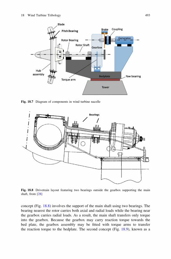
concept (Fig. 18.8) involves the support of the main shaft using two bearings. Thebearing nearest the rotor carries both axial and radial loads while the bearing nearthe gearbox carries radial loads. As a result, the main shaft transfers only torqueinto the gearbox. Because the gearbox may carry reaction torque towards thebed plate, the gearbox assembly may be fitted with torque arms to transferthe reaction torque to the bedplate. The second concept (Fig. 18.9), known as a
Fig. 18.7 Diagram of components in wind turbine nacelle
Fig. 18.8 Drivetrain layout featuring two bearings outside the gearbox supporting the mainshaft, from [28]
18 Wind Turbine Tribology 493

‘‘three-point-suspension’’ design, involves the use of one axial bearing to supportthe main shaft near the rotor, while a radial bearing supports the opposing end ofthe shaft from inside the gearbox. The gearbox itself is mounted on the bed plateand is supported by two torque arms. The third category of drivetrain (Fig. 18.10)involves the use of direct integration of the gearbox into the nacelle. In this design,all loads from the rotor enter the gearbox, with all of the rotor support bearingsintegrated into the gearbox as well. This design can be considered advantageousfor the purposes of weight reduction of the nacelle; however, incompatibilitiesbetween the gearbox and the remaining components in the nacelle can lead to earlyfailure [27].
Fig. 18.9 Drivetrain layout incorporating a three-point suspension, with one rotor shaft bearingintegrated into the gearbox, from [28]
Fig. 18.10 Drivetrain layoutwith all main bearingsintegrated in the gearbox,from [27]
494 E. J. Terrell et al.

18.5 Wind Turbine Tribological Components and Analysis
The tribological components in a wind turbine include rotor support bearings,intermediate gearbox rotor bearings, high-speed bearings, pitch bearings in thehub, epicyclic and parallel gears in the gearbox, a mechanical brake, a rollerbearing system in the yaw mechanism, and slip rings in generator (if the generatoris a doubly fed induction generator).
18.5.1 Drivetrain Bearings
Rolling-element bearings are incorporated to support the rotor and rotor shaft, thegearbox shafts, and the generator input shaft, with the bearing arrangementdepending heavily on the layout of drivetrain. Rotor shaft bearings support themain shaft as well as the rotor blades, operating under dynamic axial and radialloads as well as slow speeds (approximately 20–30 rpm). The rotor blades imposecyclic loads onto the main shaft, thus causing the shaft itself to bend, resulting inmisalignment within the bearings. Intermediate-speed and high-speed bearings inthe gearbox can also be subject to preliminary damage [29].
It is widely accepted that bearing failure is one of the major issues in windturbine drivetrain reliability, as the bearings must contend with cyclic and transientloading as well as alignment issues. Studies by Slootweg et al. [30] and Musialet al. [29] relate the start of most drivetrain failures to faulty bearings.
Bearings can be designed to handle purely axial loads, purely radial loads, or acombination of the two. Examples of each type include [31]:
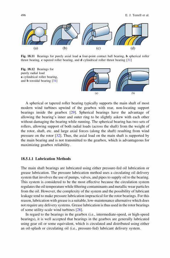
• Bearings for pure axial load: Four-point contact ball bearing, spherical rollerthrust bearing, tapered roller bearing, and cylindrical roller thrust bearing(Fig. 18.11).
• Bearings for pure radial load: Cylindrical roller bearing and toroidal bearing(Fig. 18.12).
• Bearings for combined axial and radial loads: Spherical roller bearing, taperedroller bearing, deep-groove ball bearing, angular contact ball bearing(Fig. 18.13).
It must be noted that the locating ability of bearings is designated according totheir axial load-handling abilities. A bearing that is capable of supporting axialforces in both directions is known as a locating bearing, while a bearing thatsupports only radial load is designated a non-locating, or floating, bearing. Finally,a bearing that supports axial loads in one direction is referred to as a cross-locatingbearing. Various combinations of bearings can be fitted in a given location toprovide complementary load-sharing abilities. For instance, a cylindrical rollerbearing can be situated next to a four-point contact ball bearing, such that thebearings in tandem can support both axial and radial loads.
18 Wind Turbine Tribology 495
A spherical or tapered roller bearing typically supports the main shaft of mostmodern wind turbines upwind of the gearbox with rear, non-locating supportbearings inside the gearbox [29]. Spherical bearings have the advantage ofallowing the bearing’s inner and outer ring to be slightly askew with each otherwithout damaging the bearing while running. The spherical bearing has two sets ofrollers, allowing support of both radial loads (across the shaft) from the weight ofthe rotor, shaft, etc. and large axial forces (along the shaft) resulting from windpressure on the rotor [32]. Thus, the axial load on the main shaft is supported bythe main bearing and is not transmitted to the gearbox, which is advantageous formaximizing gearbox reliability.
18.5.1.1 Lubrication Methods
The main shaft bearings are lubricated using either pressure-fed oil lubrication orgrease lubrication. The pressure lubrication method uses a circulating oil deliverysystem that involves the use of pumps, valves, and pipes to supply oil to the bearing.This system is considered to be the most effective because the circulation systemregulates the oil temperature while filtering contaminants and metallic wear particlesfrom the oil. However, the complexity of the system and the possibility of lubricantleakage tend to make pressure lubrication impractical for the rotor bearings. For thisreason, lubrication with grease is a suitable, low-maintenance alternative which doesnot require any delivery systems. Grease lubrication is thus used in the rotor bearingsof some utility-scale wind turbines [28].
In regard to the bearings in the gearbox (i.e., intermediate-speed, or high-speedbearings), it is well accepted that bearings in the gearbox are generally lubricatedusing gear oil or some equivalent, which is circulated and distributed using eitheran oil-splash or circulating oil (i.e., pressure-fed) lubricant delivery system.
Fig. 18.11 Bearings for purely axial load a four-point contact ball bearing, b spherical rollerthrust bearing, c tapered roller bearing, and d cylindrical roller thrust bearing [31]
Fig. 18.12 Bearings forpurely radial loada cylindrical roller bearing,and b toroidal bearing [31]
496 E. J. Terrell et al.

18.5.1.2 Bearing Dynamics and Wear
The dynamics of rolling element bearings can be idealized as that of twonon-conforming solids which initially touch along a point or a line. Under acompressive load in static conditions, the surfaces deform, causing a contactregion of rectangular, ellipsoidal, or spherical shape depending on the geometry ofthe contacting bodies. Contact of this nature can be analyzed according to Hertziancontact theory [33]. Studies have shown that the contact pressure distribution ismaximum in the geometrical center of the contact region, while the maximumshear stress occurs at a defined depth beneath the surface (Fig. 18.14).
As discussed by a report by Kotzalas and Doll [35], there exist a number offailure modes in wind turbine bearings. One of the most common wear modes isrolling contact fatigue, whose occurrence can often be attributed to the relativelylarge stresses that tend to appear below the surface of rolling elements. Thesesubsurface stresses can produce cracks that form beneath the surface of the rollingelements or raceways, which then propagate to the surface, causing material to beremoved from the surface and leaving behind small pits [36] (Fig. 18.15). Frettingwear can also occur within bearings, as wind gusts can cause the bearings to havelow-amplitude motion while the system is shut down for maintenance [31].
Fig. 18.14 Position of maximum stress for elastic contact between a sphere and a flat, adaptedfrom [34]
Fig. 18.13 Bearings for combined radial and axial loads a spherical roller bearing, b taperedroller bearing, c deep-groove ball bearing, and d angular contact ball bearing [31]
18 Wind Turbine Tribology 497

Finally, a phenomenon referred to as white-etch area flaking has also been deemedproblematic by some groups. Although the detailed physics of this phenomenon isnot well understood, recent studies [37, 38] have indicated that this phenomenoncan be traced back to the diffusing of hydrogen from the lubricant into the steel,causing the steel to embrittle, and making the raceway surfaces susceptible toflaking wear.
18.5.1.3 Bearing Predictive Modeling
Bearing dynamics and wear are normally predicted using either statistical ornumerical methods. The statistical approach involves the use of a fatigue lifemodel (i.e., probability density function) that provides a description of the trend offailure probability, but contains empirical constants that must be filled in usingexperimental data. The numerical approach, on the other hand, relies on thenumerical approaches to determine parameters such as the lubricant hydrodynamicpressure, lubricant film thickness, and bearing and raceway deformation.
Bearing Fatigue Life
The life theory of rolling bearings, as presented by Lundberg and Palmgren[40, 41], is a commonly used method by which the expected lifetimes of rollingbearings are predicted. According to this theory, the rating life of rolling bearings,L10, in millions of revolutions, is given as:
L10 ¼C
P
� �p
ð18:7Þ
where C is the load for which L10 = unity, P is the actual bearing load, and p is anexponential constant that has the value of p = 3 for ball bearings and p = 10/3 forroller bearings. The term L10 denotes the number of millions of cycles at which10% of bearings will begin to fail under the operating conditions given.
Fig. 18.15 Micropitting in the raceway of a spherical roller bearing, from [39]
498 E. J. Terrell et al.

Lubricant Film Thickness and Lambda Ratio
Wind turbine bearings are generally lubricated using grease or high-viscositymineral or synthetic oil to minimize surface contact. Lubrication modes are gen-erally classified according to one of three regimes—boundary lubrication, elas-tohydrodynamic lubrication (EHL), and full film (i.e., hydrodynamic) lubrication.Bearing interfaces typically operate within the EHL regime due to the largeapplied loads. Because EHL tends to take place under high loads and/or lowsliding speeds, it is characterized by the interplay between the pressure-basedelastic deformation of the contacting surfaces and the viscosity and densityenhancements of the lubricant [42–45]. The lubricant itself experiences a suddenrise in pressure, from ambient to over 1 GPa, within the interface, causing (underideal conditions) separation of the solid surfaces and minimizing of surface wear.The study of EHL has been extensively investigated by a number of researchersover the past half-century, as initiated by the pioneering work of Grubin [44, 46],and Dowson and Higginson [47, 48], and collaborators.
Assuming that both surfaces are separated by a thin film of lubricant,EHL theory is governed by equations describing the lubricant pressurization,viscosity, and density enhancement, as well as an elasticity equation that describesthe deformation of the gear tooth surfaces under load [49]. Assuming the contacttakes place along a line (i.e., spur gear contact without edge effects), the lubricantpressure, p, is governed by the Reynolds Equation:
o
ox
qh3
gop
ox
� �¼ 6U
oðqhÞoxþ 12
oðqhÞot
ð18:8Þ
where q and g are the density and viscosity, respectively, of the lubricant, t is time,and U is the sum of the surface velocities. The pressure distribution is typicallysubjected to zero-pressure inlet and Reynolds outlet boundary conditions. Thelubricant film thickness h is given by the following:
h ¼ h0 þ g0 þ d ð18:9Þwhere h0 is the reference film thickness, g0 is the undeflected geometric gapbetween the two surfaces, and d is the composite elastic deformation of bothsurfaces. The geometric gap is calculated to be:
g0 ¼x2
2Req
ð18:10Þ
where Req = (1/RA ? 1/RB)-1 is the equivalent radius of curvature as defined byHertzian theory. The surface deflection, meanwhile, is governed by the elasticityequation for semi-infinite solids under applied load:
dðxÞ ¼ � 1pE0
Za
�b
pðsÞ ln x� sj jds ð18:11Þ
18 Wind Turbine Tribology 499

where m is Poisson’s ratio and E0 = 2((1 - mA2)/EA ? (1 - mB
2)/EB)-1 is theYoung’s modulus.
The lubricant viscosity, meanwhile, has been shown to increase with increasingpressure. A simplified model that describes this phenomenon, known as piezo-viscosity, is given by the Barus Equation, as follows:
g ¼ g0 expðapÞ ð18:12Þ
where g0 is the lubricant viscosity at ambient pressure. The lubricant density,which also increases within the EHL interface, can be modeled by means of adensity–pressure relationship presented by Dowson and Higginson [48]:
q ¼ q0ð1þ cpÞð1þ kpÞ ð18:13Þ
where c = 2.266 9 10-9 Pa-1, k = 1.683 9 10-9 Pa-1, and q0 is the density atambient pressure.
Equations 18.8–18.13 can be solved simultaneously using iterative or inversenumerical methods [50]. Studies have shown that the film thickness h within theEHL interface is approximately uniform, with the exception of a sudden decreasein h that occurs near the exit of the interface (Fig. 18.16).The lubricant pressuredistribution, meanwhile, is found to have a similar parabolic profile as that whichwould be predicted for Hertzian contact (Fig. 18.17), with the exception of apressure spike that occurs in the same location as where the film thickness sud-denly drops off. Both the pressure and film thickness profiles have been analyzedextensively, and verified experimentally.
The film thickness distribution within EHL is a subject of tremendous interestbecause the lubricant film is the primary means by which the surface asperities ofthe gear teeth are separated from one another. The EHL film thickness is generallyknown to have a relatively flat region followed by a sharp decrease at the lubricantexit. It is thus characterized by two parameters, namely, the central film thicknesshc, and the minimum film thickness hmin. If the combined height of the asperities oneach mating gear is larger than either the central or minimum film thickness,asperity–asperity contact may occur. Such contact will inevitably lead to surfacedamage such as abrasive wear, micropitting, scuffing, and crack formation. Tocharacterize the effect of film thickness separation versus asperity–asperity contact,
Fig. 18.16 Film thicknessdistribution in EHL, from[51]
500 E. J. Terrell et al.

Tallian [52] introduced a parameter known as lambda ratio k, known asfollows [53]:
k ¼ hcffiffiffiffiffiffiffiffiffiffiffiffiffiffiffir2
1 þ r22
p ð18:14Þ
where r1 and r2 are the root-mean-square (RMS) roughness of the two contactingsurfaces. Studies have shown that the lambda ratio governs the wear pattern, ifany, that is experienced by the geartrain, according to Table 18.1.
It can thus be seen to be advantageous to have a lambda ratio that is as large aspossible in order to minimize the possibility of gear wear. Recent efforts have thusbeen taken towards improving the surface finish of gears. Experimental tests byDoll and collaborators [54, 55] have shown that superfinishing (surface polishingto sub-micron roughness) causes noticeable improvement in anti-wearperformance.
18.5.2 Gearbox
Utility-scale fixed-speed and variable-speed wind turbines rely upon a gearbox toincrease the slow-moving, high-torque input from the rotor to the high-speedoutput that is required by the generator. The gearing ratio, G, for a wind turbinetransmission is defined as follows:
G ¼ ngenerator
nrotor
ð18:15Þ
where ngenerator is the rotational speed of the generator and nrotor is the rotationalspeed of the rotor, both in rpm. A wind turbine that incorporates a generator
Fig. 18.17 Lubricantpressure distribution in EHL,from [51]
Table 18.1 Wear patternsfor various lambda ratios(reproduced from [53])
k value Wear pattern
k\ 1 Surface smearing, deformation, abrasive wear1 B k\ 1.5 Smoothing of rough areas, spallation1.5 B k\ 3 Some smoothing of rough areas3 B k\ 4 Minimal wear4 B k Full separation by EHL film
18 Wind Turbine Tribology 501

operating at 1,500 rpm and rotor operating at 20 rpm would require a gearbox withgearing ratio of G = 75 [56]. The total gearing ratio can be considered a productof the ratio of the individual stages, i.e.,
G ¼ G1 � G2 � � � � GN ð18:16Þ
where N is the number of stages in the gearbox. Modern turbines generallyincorporate at least three gearing stages in the gearbox. One or more stages isgenerally of a planetary, or epicyclic configuration, while the remaining stagesare typically of a parallel (i.e., gears with fixed, parallel axes) configuration(Fig. 18.18). Epicyclic gears incorporate multiple outer gears whose centersrevolve around a single, center gear. The revolving gears are denoted as‘‘planets,’’ while the center gear is the ‘‘sun’’. An outer ring gear is locatedoutside the planet gears [56]. For wind applications, the number of planets isnormally chosen to be three. Epicyclic gears have seen significant use in windapplications due to the fact that they can transfer a higher torque density thanparallel stages, which enables them to be relatively lightweight and compact ascompared to parallel gears of similar load capacity. The epicyclic stage is nor-mally designed for gear ratios up to Gi = 7, while parallel stages can handlegear ratios up to Gi = 5 [27].
Although the electrical systems in wind turbine systems are generally mostprone to failure, gearbox and components tend to be the costliest to maintain andreplace [10, 57]; thus gearbox reliability is considered a critical issue in windturbine design and operation. Studies have shown that less-than-desired reliability
Fig. 18.18 Configuration of three-stage gear for 2–3 MW wind turbine, from [28]
502 E. J. Terrell et al.

in wind turbine gearboxes can be attributed to a number of different factors,including the following:
• Wind gusts and generator connection/disconnection from the electrical grid maycause undesired load reversals in the gearbox, which can lead to excessivecontact stresses in the gear flanks [35].
• Undesired movement of the drivetrain, which can be caused by deformationswithin the bedplate, can cause misalignment of the gearbox with the generatorshafts. This misalignment results in unexpected damage to the high-speedbearings, which leads to damage in the high-speed gears [56].
• The gearbox may be subject to particulate contamination, which may lead tosurface pitting in the gears.
• Excessively high oil temperatures may result in scuffing wear in the gears [28],thus necessitating the use of oil coolers and filters in the lubricant deliverysystem.
18.5.2.1 Gear Geometry
The tooth profile of spur and helical gears is based on a truncated involute curve(Fig. 18.19), which is defined as a curve that connects a locus of points that aregenerated at the end of a taut string when it is unwound from the tangent of a basecircle (known as the evolute). Litvin and Fuentes [58] involute gearing, firstproposed by Euler, has many advantages in its use, including: (1) ease of manu-facturability, (2) lack of transmission errors when the gear center distance ischanged, and (3) the tooth-to-tooth force is applied along a constant line of actionthroughout the time of meshing. Through geometrical analysis, it can be found thatthe geometry of contacting involute gear teeth can be represented by circular discsof varying radii. For this reason, the contact theory of Hertz [33] has the ability toprovide a reasonable solution for the elastic deformation, pressure distribution, andreal contact area between mating teeth, although it must be noted that Hertziananalysis is based on the assumption of static, dry (nonlubricated), and friction-less conditions—none of which are experienced between moving gear teeth.A more appropriate analysis involves the combined study of lubricant flowand pressurization along with deflection of tooth surfaces, as will be discussed inSect. 18.5.1.3.
Both spur and helical gearing geometries are common within wind turbinegearboxes. In the case of spur gears, the contact region is a straight line across thedepth of the tooth, such that at any time either one or two teeth are in contact.Helical gears, however, are skewed in the axial direction, causing each tooth toappear as a segment of a helix. Because the teeth are angled with respect to theaxis of rotation, the contact region is composed of a series of slanted lines, withseveral teeth in contact at a given time. The angled teeth engage more graduallythan do spur gear teeth, causing them to run more smoothly and quietly [60].In regard to loading, spur gears impose only radial loads on their bearings.
18 Wind Turbine Tribology 503

Single helical gears, meanwhile, impose both thrust and radial loads on theirbearings. Double helical gears, which are side-to-side combinations of helicalgears of opposing axial skewness, develop equal and opposite thrust reactionswhich serve to cancel out the thrust load [61].
18.5.2.2 Gear Loads and EHL Calculations
The geometry of contacting spur gear teeth is likened to that which is formed bythe contact of two rotating circular discs of varying radii. The radii of curvature(Fig. 18.20) of the driving gear (denoted as Gear A) and the driven gear (denotedas Gear B) are given as:
RA ¼ rA sinðwÞ þ S ð18:17aÞ
RB ¼ rB sinðwÞ � S ð18:17bÞ
where rA and rB are the pitch radii of Gears A and B, respectively, w is the contactangle, and S is the distance of the contact point from the pitch point [53].
Fig. 18.20 Equivalent radiusof curvature for contactinggear teeth, from [62]
Fig. 18.19 Geometry of involute spur gears a involute curve generation, b spur gear toothnomenclature, from [59]
504 E. J. Terrell et al.
The torque that is applied to the gear is given by [63]:
T ¼ P
xð18:18Þ
where P is the transmitted power, and x = 2pN is the rotation speed. The normalload that is applied to each meshing tooth is then found as:
WA ¼ sAT
RA cosðwÞ
� �ð18:19aÞ
WB ¼ sBT
RB cosðwÞ
� �ð18:19bÞ
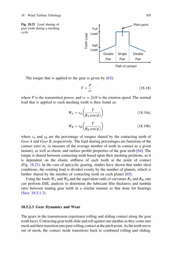
where sA and sB are the percentage of torques shared by the contacting teeth ofGear A and Gear B, respectively. The load sharing percentages are functions of thecontact ratio mc (a measure of the average number of teeth in contact as a giveninstant), as well as elastic and surface profile properties of the gear teeth [64]. Thetorque is shared between contacting teeth based upon their meshing positions, as itis dependent on the elastic stiffness of each tooth at the point of contact(Fig. 18.21). In the case of epicyclic gearing, studies have shown that under idealconditions, the rotating load is divided evenly by the number of planets, which isfurther shared by the number of contacting teeth on each planet [65].
Using the loads WA and WB and the equivalent radii of curvature RA and RB, onecan perform EHL analysis to determine the lubricant film thickness and lambdaratio between mating gear teeth in a similar manner as that done for bearings(Sect. 18.5.1.3).
18.5.2.3 Gear Dynamics and Wear
The gears in the transmission experience rolling and sliding contact along the geartooth faces. Contacting gear teeth slide and roll against one another as they come intomesh and then transition into pure rolling contact at the pitch point. As the teeth moveout of mesh, the contact mode transitions back to combined rolling and sliding.
Pitch pointFull
Load
HalfLoad
Double
Pair Pair Pair
Path of contact
DoubleSingle
Too
th L
oad
Fig. 18.21 Load sharing ofgear tooth during a meshingcycle
18 Wind Turbine Tribology 505

In the case of helical gears, it must be noted that an involute helical gear can beanalyzed as a set of spur gears with infinitely small width, with each of the spur gearsrotated with respect to the adjacent gear to comprise the helical shape [66].
A review by Errichello [51] classifies gear failure according to the categories ofoverload, bending fatigue, Hertzian fatigue, wear, and scuffing. The primaryfailure modes in wind turbine gears are generally scuffing, pitting, and abrasivewear, as discussed in the following sections.
Scuffing
This failure mode is caused by rapid adhesion and/or welding of the asperities ofcontacting gear teeth, followed by the tearing of one or both surfaces as the gearsteeth slide past one another (Fig. 18.22). It results in the transfer of material fromone tooth surface to another. Scuffing damage can occur if the lubricant filmthickness is too low, in which case the oxide layers that normally protect the geartooth surfaces may be penetrated, and the bare metal surfaces may weld together,resulting in the tearing of the metallic junction.
Although small lubricant film thickness is one condition that is necessary forscuffing to occur, it by itself will not cause scuffing single-handedly. On thecontrary, studies have shown that the metallic welding phenomenon that occursduring scuffing is preceded by localized frictional heating, which itself is the resultof large contact pressures and elevated sliding velocities between the gear toothsurfaces. The critical temperature theory presented by Blok [68], a widely usedcriterion for predicting scuffing, predicts that scuffing will occur when the maxi-mum contact temperature exceeds a given value. To minimize the possibility ofscuffing, mineral and synthetic lubricants may include anti-scuff, or extreme
Fig. 18.22 Gear tooth surfaces with scuffing damage, from [67]
506 E. J. Terrell et al.

pressure (EP), additives, which contain sulfur, phosphorus, or other compoundsthat create a protective layer on gear surfaces [31].
Pitting
This failure mode, considered to be a Hertzian failure mode, is characterized bythe formation of surface or subsurface cracks, which propagate to the surface,causing small pits to remain in the surface. The formation of micron-scale pits isknown as micropitting. It must be noted that when a micropitted surface is sub-jected to subsequent loading cycles, several micropits may grow together, leavingbehind a larger pit known as a macropit. The formation of macropits generallyleads to vibration and transmission error within the gearbox, as well as overalltooth failure [69]. The probability of micropitting can be reduced by keeping thelubricant film thickness (i.e., lambda ratio) high, as damage can most readily occuron gear teeth with rough surfaces or with an insufficient lubricant film. Surfacetreatment techniques such as carburizing and superfinishing [70] have promise forincreasing pitting resistance, although the cost of these procedures may be ofconcern.
Abrasive Wear
This failure mode is generally caused by hard contaminant particles that entraininto the interface. Particles that are introduced between sliding interfaces abradematerial off each surface creating indentations. These indents create high localstresses and are the primary cause for surface-related fatigue failures [71].Contaminant particles can be created during the manufacturing, assembly, or run-in processes, be ingested from the environment through breathers or seals, or beinternally generated. Further details on particulate contamination in wind turbinedrivetrains are given in Sect. 18.6.2.
Bending Fatigue
In addition to lubricant film thickness, an important consideration in geartrainoperation involves the bending strength of the gear teeth. If the bending stressextends beyond design criteria, cracks may initiate at the base of the tooth andpropagate through its base, causing it to break away from the base of the gearwheel [72]. Most gears, particularly, high contact ratio spur gears, may continue totransmit load after a tooth failure. However, the loss of a gear tooth may causeincreased levels of noise and vibration that may lead to subsequent damage to thebearings or other areas of the gearbox [73].
The well-known Lewis equation [59, 74], presented by Wilfred Lewis in 1892,is a classical method to estimate the bending stress in spur gear teeth. According tothe Lewis equation, the bending stress r at the tooth root is given by the following:
18 Wind Turbine Tribology 507

r ¼ W
pBy
where W is the transmitted load, p is the circular pitch, B is the width of the toothface, and y is a dimensionless form factor which depends on the shape of the tooth.More recently, workers such as Dolan and Broghamer [75] and Kelley andPedersen [76] have developed more sophisticated formulas for gear tooth bendingstress based upon photoelastic experimental measurements. More recent studieshave employed FEA to enable an accurate prediction of bending stresses [77, 78].
18.5.2.4 Fatigue Life Prediction
The Palmgren–Miner Linear Cumulative Fatigue Damage Theory (Miner’s Rule)is used to calculate the resultant pitting or bending fatigue lives for gears that aresubjected to highly varying loads [79, 80]. According to Miner’s Rule, failureoccurs when:
n1
N1þ n2
N2þ � � � þ ni
Ni¼ 1
where ni is the number of cycles at the ith stress level, Ni is the number of cycles tofailure corresponding to the ith stress level, and ni/Ni is the damage ratio at the ithstress level. It must be noted that a significant limitation in the Palmgren–Minertheory is that the loading sequence (i.e., the order of applied loads) is notconsidered.
18.5.2.5 Power Loss and Noise
Modern gearboxes produce relatively small power losses, with the main sources ofpower loss being attributed to tooth-flank friction. As a rule of thumb, parallel gearlosses are assumed to be 2% of the full load per stage, while planetary gear lossesare assumed to be 1% per stage. The frictional losses result in heat generation andnoise emission [22]. Although the generated noise from the gearbox constitutesonly a small fraction of the power loss, it can still be noticeable to the point whereit can draw complaints from nearby residents (in the case of land-based turbines).To minimize noise, gearbox manufacturers must ensure smooth gear meshing byusing high-quality design and manufacturing techniques [28]. The nacelle fairingis also acoustically insulated to prevent sound transmission into the air.
18.5.3 Pitch and Yaw Bearings
Blade pitching systems are used to control power and rotor speed, while yawsystems are used to orient the rotor perpendicular to the wind direction.
508 E. J. Terrell et al.

The bearings that are used for pitch and yaw systems are often discussed withina similar context, as their ranges of motion and wear modes are often similar toone another. Additionally, both pitch and yaw bearings experience similar typesof loading—namely, an eccentrically applied thrust, which can be divided intoa pure axial load and an overturning moment load [81]. As a result, the fatiguelives of both pitch and yaw bearings can be estimated using a single life ratingpredictive approach. It is expected that the static loads that are applied to pitchand yaw bearings will cause some degree of permanent deformation in theraceways and rolling elements; however, experience has shown that a defor-mation of 1/10,000th of the rolling element diameter is tolerable for successfuloperation.
18.5.3.1 Pitch Bearing
Blade pitching systems, which actively rotate blades along their longitudinal axes,are used in active-pitch and active-stall controlled wind turbine systems. Thepitching motion is typically driven by hydraulic actuators [82] or electric motors.The pitch control system is critical for utility-scale turbines, as it allows the systemto optimize power extraction and minimize unnecessary loads. Above all else, thepitching system is employed as a fail-safe aerodynamic brake to stop the turbinewhen wind speeds become excessive [28], thus making the pitching system criticalfor preventing catastrophic failure of the whole turbine [8]. While a pitching rangeof 20–25� is generally sufficient for controlling the power and speed of the rotor,aerodynamic braking necessitates that the blades have the ability to be placed intothe feathered position (i.e., parallel to oncoming airflow), which minimizes lift,causing the turbine to brake.
The use of a pitching system necessitates that the blades be exclusively sup-ported by rolling element bearings at their roots. The bearings themselves aresubject to large static loads as well as centrifugal and cyclic bending loads whenthe turbine is in operation. Most modern turbines use four-point contact bearingsor ball bearing slewing rings for pitch operation. Turbines with smaller rotorblades can suffice with a single-row arrangement in their pitch bearings, whilelarger rotor blades require double-row four-point bearings.
Pitch bearings are generally lubricated using grease with a high-viscosity baseoil. Similar to drivetrain bearings, the grease in pitch bearings should maintainthe thickest lubricant film possible to prevent premature damage. Because pitchbearings operate under slight oscillatory motion, fretting wear and/or falsebrinnelling can occur when the lubricant film is insufficient. Additionally, areport by the National Renewable Energy Laboratory (NREL) suggested thepitch bearing be periodically (i.e., once per day) rotated through a large-amplitude oscillation cycle in order to redistribute grease that has been previ-ously displaced [81].
18 Wind Turbine Tribology 509
18.5.3.2 Yaw Bearing
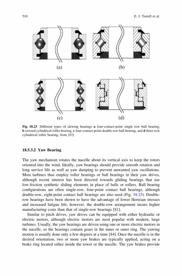
The yaw mechanism rotates the nacelle about its vertical axis to keep the rotorsoriented into the wind. Ideally, yaw bearings should provide smooth rotation andlong service life as well as yaw damping to prevent unwanted yaw oscillations.Most turbines thus employ roller bearings or ball bearings in their yaw drives,although recent interest has been directed towards gliding bearings that uselow-friction synthetic sliding elements in place of balls or rollers. Ball bearingconfigurations are often single-row, four-point contact ball bearings, althoughdouble-row, eight-point contact ball bearings are also used (Fig. 18.23). Double-row bearings have been shown to have the advantage of lower Hertzian stressesand increased fatigue life; however, the double-row arrangement incurs highermanufacturing costs than that of single-row bearings [81].
Similar to pitch drives, yaw drives can be equipped with either hydraulic orelectric motors, although electric motors are most popular with modern, largeturbines. Usually, the yaw bearings are driven using one or more electric motors inthe nacelle, so the bearings contain gears in the inner or outer ring. The yawingmotion is usually done only a few degrees at a time [84]. Once the nacelle is in thedesired orientation, two or more yaw brakes are typically applied, acting on abrake ring located either inside the tower or the nacelle. The yaw brakes provide
Fig. 18.23 Different types of slewing bearings a four-contact-point single row ball bearing,b crossed cylindrical roller bearing, c four-contact-point-double row ball bearing, and d three-rowcylindrical roller bearing, from [83]
510 E. J. Terrell et al.

stabilization of the nacelle under varying wind loads, while also preventing theyaw drive from absorbing the yawing moment.
18.5.3.3 Fatigue Life Prediction for Pitch and Yaw Bearings
Because pitch and yaw bearings exhibit oscillatory motion and do not spin con-tinuously, the life estimation theory of Lundberg and Palmgren (Eq. 18.7), whichpredicts lifetime in terms of number of rolling cycles to probable failure, is notdirectly applicable. However, studies have shown that the Lundberg–almgrenestimation can be modified to apply to oscillating bearings based upon the criticalangle of oscillation hcrit, which is calculated as:
hcrit ¼
720�
Zð1� cÞ ðouter racewayÞ720�
Zð1þ cÞ ðinner racewayÞ
8>><>>:
ð18:20Þ
where Z is the total number of rolling elements (whether loaded or unloaded) and cis the contact angle. If the oscillation angle (denoted as h) is less than hcrit, eachrolling element has its own discrete stressed volume within the raceway and themodified axial load rating is given by:
Ca;osc ¼Ca
180�
h
� �3=10
Z0:033 ðball bearingsÞ
Ca180�
h
� �2=9
Z0:028 ðroller bearingsÞ
8>>><>>>:
ð18:21Þ
where Ca is the actual axial load. However, if h is greater than hcrit, the contactstresses of the individual rolling elements overlap, and the modified axial loadrating is given by:
Ca;osc ¼ Ca180�
h
� �1=p
ð18:22Þ
where p = 3 for ball bearings and p = 4 for roller bearings. If the speed of pitchand yaw bearings is denoted in terms of oscillations per minute, the fatigue life,expressed in terms of millions of oscillations, is calculated as [36, 81]:
L10 ¼Ca;osc
Pea
� �3
for thrust ball bearings; or ð18:23aÞ
L10 ¼Ca;osc
Pea
� �10=3
for thrust roller bearings; ð18:23bÞÞ
where Pea is the dynamic equivalent axial load.
18 Wind Turbine Tribology 511
18.5.4 Mechanical Brake
Modern wind turbines incorporate a mechanical brake on the high-speed section ofthe drivetrain, normally between the gearbox and the generator. This mechanicalbrake, which almost always is in the form of a disk brake, is primarily responsiblefor locking down the rotor during shutdown such that servicing and repair workcan take place. Beyond functioning as a parking brake, some turbines employ themechanical brake as a secondary braking system to complement aerodynamicbraking during operation. On larger wind turbines, the mechanical brake is situatedon the high-speed side of the gearbox to minimize the size and weight of the brakedisk. Because of its position on the high-speed shaft, the use of the mechanicalbrake can be detrimental towards gearbox reliability. At standstill, braking loadsoftentimes contend with forces from wind turbulence, causing small oscillatorymovements of the gear teeth. These motions can result in fretting wear in the gearteeth [28].
18.6 Contamination Effects
Gear oil recirculates through wind turbine gearboxes, lubricating mating surfacesand removing heat. Unfortunately, contaminant particles suspended in the gear oil,as well as water in the parts per million (ppm) range, can significantly degrade theperformance and reliability of gearboxes.
Sources of contaminant particles include: cutting and grinding swarf built-infrom manufacturing, ingression of airborne abrasives through vents and mechan-ical seals, and internally generated wear debris and metal oxide corrosion products.To quantify particulate contamination levels, the International Organization forStandardization (ISO) created cleanliness codes that serve as a universal standardfor measuring and reporting contamination levels in fluids. Based upon a millilitersample of lubricant, ISO codes are defined according to the nomenclature a/b/c,where a, b, and c denote the number of particles greater than 4, 6, and 14 lm insize, respectively, per milliliter of lubricant. It can be easily seen that the lower thecode, the cleaner the lubricant, and thus the aim for wind turbine filtration andmonitoring is to keep the code as low as possible. In modern turbines, well-filteredgearbox lubricants may have a code of 16/14/11 or below.
In addition to particulate contaminants, small amounts of water dissolve inlubricating oils and hydraulic fluids. The maximum amount of dissolved water (thesaturation level) is typically 300–500 ppm, depending on base stock and additives.Water contamination in excess of the saturation level is termed free water, whichsettles to low points of the system. Emulsified free water—droplets on the order of1 lm—remains suspended in the oil and gives it a hazy to milky appearancedepending on the amount present. Sources of water include humidity ingressing
512 E. J. Terrell et al.

through vents and mechanical seals as well as liquid water incurred duringtransportation and storage.
18.6.1 Contamination-Based Tribological Problems
Problems caused by particle and water contamination in wind turbine gearboxesare listed in Tables 18.2 and 18.3. Synopses of these problems are provided in thefollowing sections.
Table 18.2 Hard particle contamination problems in wind turbine gearboxes
Problem Summary
Surface-initiated fatiguespalling
3-body wear in rolling contacts. Hard ductile particles dent surfaces,followed by crack propagation leading to fatigue spalling, a.k.a.pitting, cratering of surfaces
Abrasive wear 3-body wear in sliding contacts. Hard particles plough through and cutaway surface material, leading to loss of clearance and roughsurfaces accompanied by high friction
Accelerated oiloxidation
Catalytic surfaces of fresh metal wear debris accelerate oil oxidation,lead to acidity, oil thickening, and sticky fouling deposits
Table 18.3 Water contamination problems in wind turbine gearboxes
Problem Summary
Corrosion Due to free water, especially if acids present from oil degradation and/ormicrobial growth. Ion currents in aqueous solution. Leads to pitting,leakage, and breakage
Foaming Due to free water. Leads to air blockage within the oil distribution system,and spillage
Loss of oil film Due to free water. Water in contact zone cannot support load, allowingopposing surfaces to contact. Results in adhesive wear, high friction,and seizure
Additive drop-out Due to free and dissolved water. Depletion of hydrophilic additives. Alsobreaking colloidal suspensions of additives. Leads to loss of additivesand fouling of parts
Microbial growth Due to free water. Colonization of oil by bacteria and/or fungi. Results in:acids, fouling slimes; health issues
Surface-initiated Due to dissolved water carried by gear oil to the tips of propagating cracks.Surfaces of fresh cracks are highly reactive, dissociating watermolecules into O2 and H2. H2 migrates into and weakens steel byhydrogen embrittlement. Cracks spread faster, reducing life of rollingelements and resulting in fatigue spalling, pits, and craters
Fatigue spalling
Accelerated oiloxidation
Due to dissolved water, especially if metal wear debris present. Increasesrate of oil oxidation by up to 2 orders of magnitude. Leads to acidity, oilthickening, fouling deposits
Hydrolysis Due to dissolved water. Decomposition of ester-based additives. Leads toloss of additives, formation of acids, and sometime fouling gels
18 Wind Turbine Tribology 513
18.6.1.1 Surface-Initiated Fatigue Spalling
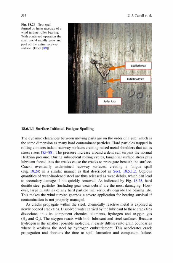
The dynamic clearances between moving parts are on the order of 1 lm, which isthe same dimension as many hard contaminant particles. Hard particles trapped inrolling contacts indent raceway surfaces creating raised metal shoulders that act asstress risers [85–88]. The pressure increase around a dent can surpass the normalHertzian pressure. During subsequent rolling cycles, tangential surface stress pluslubricant forced into the cracks cause the cracks to propagate beneath the surface.Cracks eventually undermined raceway surfaces, creating a fatigue spall(Fig. 18.24) in a similar manner as that described in Sect. 18.5.1.2. Copiousquantities of wear-hardened steel are thus released as wear debris, which can leadto secondary damage if not quickly removed. As indicated by Fig. 18.25, hardductile steel particles (including gear wear debris) are the most damaging. How-ever, large quantities of any hard particle will seriously degrade the bearing life.This makes the wind turbine gearbox a severe application for bearing survival ifcontamination is not properly managed.
As cracks propagate within the steel, chemically reactive metal is exposed atnewly opened crack tips. Dissolved water carried by the lubricant to these crack tipsdissociates into its component chemical elements, hydrogen and oxygen gas(H2 and O2). The oxygen reacts with both lubricant and steel surfaces. Becausehydrogen is the smallest possible molecule, it easily diffuses into grain boundarieswhere it weakens the steel by hydrogen embrittlement. This accelerates crackpropagation and shortens the time to spall formation and component failure.
Fig. 18.24 New spallformed on inner raceway of awind turbine roller bearing.With continued operation thespall would rapidly grow andpeel off the entire racewaysurface. (From [89])
514 E. J. Terrell et al.

Figure 18.26 shows decreasing bearing life as the concentration of dissolved waterincreases.
18.6.1.2 Abrasive Wear
Hard particles in sliding contacts (such as between gear teeth and in journalbearings) plough through and cut away component surfaces, resulting in frictionallosses, elevated oil temperature, loss of fit and tolerance, and reduction in powertransmission efficiency. The major offenders are abrasives used in manufacturingand gritty airborne minerals such as silica dust.
0.001
0.01
0.1
1
40
Debris Particle Size
Lif
e R
elat
ive
to N
on
-Den
ted
Bea
rin
gs
Hard Ductile (e.g. T15 & 52100 Steel) Hard Rigid (e.g. Al2O3 & SiC) Hard Friable (e.g. TiC)
1301201101009080706050
Fig. 18.25 Hard ductile particles, such as gear tooth wear debris, produce the greatest decrementto bearing life. More fragile particles tend to shatter in contact zone and produce less damage perparticle. However, damage also increases with concentration for any type of hard particlecontaminant [90]
Water Contamination & Bearing Life
0.0
1.0
2.0
3.0
4.0
5.0
6.0
7.0
0 100 200 300 400 500 600
Water (ppm)
Rel
ativ
e B
eari
ng
Lif
e
Target
Current
Fig. 18.26 Dissolved waterand bearing life. Saturationlevel of water in oil is500 ppm. Bearings operatingin oil with lower levels ofdissolved water have longerlife. ‘Current’ refers totypical water contaminationlevels in wind turbinegearboxes; ‘Target’ refersto 125 ppm water levelachieved through improvedcontamination control.(Original data from [91],and revised in [92])
18 Wind Turbine Tribology 515

18.6.1.3 Oil Oxidation
Because of difficulty, expense, and safety issues, wind turbine operators strive tominimize the frequency of gear oil changes. The enemy is oil degradation, whichincludes loss of additives, excessive accumulations of fine particles, and especiallyoil oxidation. This well-documented oxidation mechanism starts when oxygenatoms are incorporated into oil molecules producing chemically reactive freeradicals, which in turn initiate chain reactions involving thousands of oil moleculesand producing acids and polymeric compounds. The acids promote corrosion. Thepolymers are gummy substances that: (1) thicken the oil, fostering filter bypassingand lubricant starvation during cold starts, (2) foul passages and flow controls,another source of lubricant starvation, and (3) coat and thermally insulate heatexchange surfaces, fostering excessive heat build-up and elevated temperaturesduring operation.
Antioxidants (free-radical scavengers) are incorporated into gear oil additivepackages to intercept the free radicals and terminate the chain reaction. When theantioxidant additives become depleted, oxidation takes over, and the degraded oilrequires replacement. A strategy for extending oil life and oil change intervals is toreduce the rate of depletion of antioxidant additives. This is accomplished by:(1) keeping the oil cool, (2) inhibiting the generation of metal wear debris andsequestering fresh debris away from hotter zones, and (3) keeping water levelsbelow 100–200 ppm. Regarding temperature, the rate of oil oxidation tends tofollow the simple, yet reliable, estimation for oil temperature: The rate of achemical reaction approximately doubles for every 10�C increase in temperature.Maintaining gear oil operating temperature below *50�C will alleviate mostoxidation issues due to hot oil.
The surfaces of fresh metal wear particles are catalytic, promoting the forma-tion of free radicals and accelerating oil oxidation. As summarized in Table 18.4,one classic study found fresh metal surfaces accelerated oxidative oil degradationby 6–8 times, as measured by increasing Total Acid Number (TAN) values.Per unit surface area, copper was the worst offender (such as from tubing andbronze bushings). However, the greater amounts of iron-containing wear debrisfound in gearboxes are likely the major offenders for wind turbines. In the samestudy, water by itself was found to accelerate oil oxidation as rapidly as copper.However, water together with either copper or iron accelerated the rate of oiloxidation by a factor of 300.
Table 18.4 Effects of metalsand water on oil oxidation.Adapted from [93]
Condition Hours (h) TAN increase
Clean and dry 3,500 0.17Iron 3,500 0.65Copper 3,500 0.79Water 3,00 0.80Water ? Iron 500 8.1Water ? Copper 40 11.2
516 E. J. Terrell et al.

18.6.1.4 Hydrolysis
In addition to oxidation, wind turbine gear oils can degrade through the directhydrolysis of ester-based additives. These types of additives are synthesized byreacting alcohols and acids to produce the required esters, along with water as aby-product. In operating systems, dissolved water drives the reaction in reverse,decomposing esters back into alcohols (mostly innocuous) and acids (quiteharmful), along with depletion of the ester-based additives. Acids produced byhydrolysis promote corrosion and can also react with metals to produce fouling gels.
18.6.1.5 Additive Drop-Out
Another form of oil degradation is additive drop-out. Some gear oil additives havestrong affinity for water (hydrophilic polar additive molecules). They becomeunavailable by congregating in and around water droplets. Furthermore, highconcentrations of dissolved water can break colloidal suspensions of finely dividedpowders sometimes used as anti-wear additives, resulting in dumping of massiveamounts of material. Not only are these additives inactivated by water, but asillustrated in Fig. 18.27, additive drop-outs can completely foul components andmake them inoperable.
18.6.1.6 Corrosion
Galvanic corrosion requires current of ions in aqueous solution, and therefore thepresence of free water. Even a thin film of water suffices. NaCl salt accelerates thecorrosion of metals, making offshore and coastal marine environments especially
Fig. 18.27 Water-inducedadditive drop-out fouling agearbox thermostat, renderingit inoperative (COT-Puritech,Inc.)
18 Wind Turbine Tribology 517

sensitive to this wear mode. Corrosion results in pitting, leakage, weakening, andbreaking of parts, and release of abrasive particles into the oil (such as iron oxide,better known as rust).
18.6.1.7 Microbial Growth
To grow and multiply microbes need three requirements: moderate temperatures,food, and free water. Many strains of bacteria and molds will metabolize gear oil. Iffree water is present along with temperatures ranging from 15 to 52�C (60–125 F),these will thrive. Consequences include accumulation of acids (promoting corro-sion since free water is present), and the formation of biological slimes that foulflow passages and moving parts. Microbial colonization of lubricants is alsoassociated with fetid odors, asthma, and skin allergies.
18.6.2 Contamination Control
Strategies for ameliorating the harmful effects of oil contamination have beendeveloped over the past 40 years in the construction, mining, agriculture, andaerospace industries, and some of the knowledge gained is currently being appliedto the wind turbine industry. Some of the practices that are currently being rec-ommended for the manufacture, assembly, and maintenance of wind turbines arelisted in Table 18.5.
Additionally, an appropriately designed oil filtration system is critical forminimizing the possibility of early gear or bearing failure. Most wind turbinesincorporate one or more filtration systems to remove debris and contaminants fromthe lubricant. Inline filters, which are placed within the same circulation line as thedelivery system, are now standard on most current turbines. To keep the gear oilcool, a heat exchanger is used prior to returning the filtered oil back to the gearbox,typically keeping the maximum oil temperature below 70�C [94]. Some turbinesare also designed with an offline or bypass filtration system. These systems includea separate pump that circulates oil through an independent filter. Figure 18.28depicts a typical contamination control system, complete with a water absorptionfilter. Offline particle filters are needed only if online filters are insufficient tomaintain lubricant cleanliness.
18.6.2.1 Rating Particle Filters
The international standard method for rating lube and hydraulic filters is theMulti-Pass Test [95]. As illustrated in Fig. 18.29, a slurry of silica particles iscontinuously fed into the test circuit. As particles flow into the filter under test,some are captured, and the remainder continues to recirculate. Throughout the
518 E. J. Terrell et al.
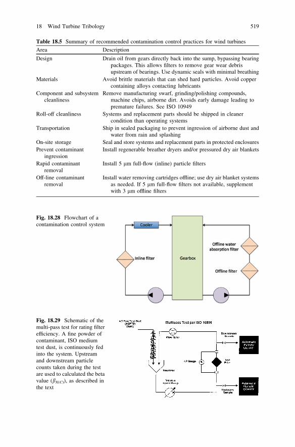
Table 18.5 Summary of recommended contamination control practices for wind turbines
Area Description
Design Drain oil from gears directly back into the sump, bypassing bearingpackages. This allows filters to remove gear wear debrisupstream of bearings. Use dynamic seals with minimal breathing
Materials Avoid brittle materials that can shed hard particles. Avoid coppercontaining alloys contacting lubricants
Component and subsystemcleanliness
Remove manufacturing swarf, grinding/polishing compounds,machine chips, airborne dirt. Avoids early damage leading topremature failures. See ISO 10949
Roll-off cleanliness Systems and replacement parts should be shipped in cleanercondition than operating systems
Transportation Ship in sealed packaging to prevent ingression of airborne dust andwater from rain and splashing
On-site storage Seal and store systems and replacement parts in protected enclosuresPrevent contaminant
ingressionInstall regenerable breather dryers and/or pressured dry air blankets
Rapid contaminantremoval
Install 5 lm full-flow (inline) particle filters
Off-line contaminantremoval
Install water removing cartridges offline; use dry air blanket systemsas needed. If 5 lm full-flow filters not available, supplementwith 3 lm offline filters
Fig. 18.28 Flowchart of acontamination control system
Fig. 18.29 Schematic of themulti-pass test for rating filterefficiency. A fine powder ofcontaminant, ISO mediumtest dust, is continuously fedinto the system. Upstreamand downstream particlecounts taken during the testare used to calculated the betavalue (bX(C)), as described inthe text
18 Wind Turbine Tribology 519
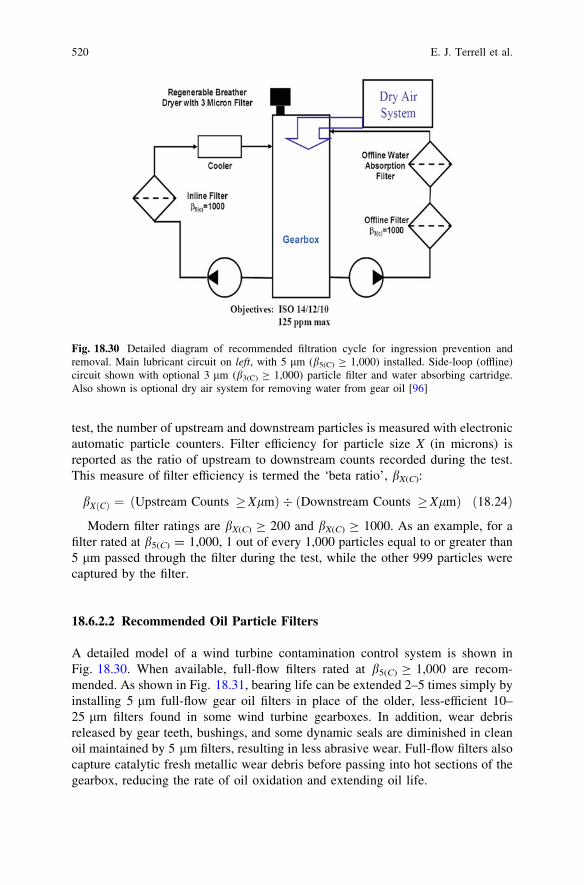
test, the number of upstream and downstream particles is measured with electronicautomatic particle counters. Filter efficiency for particle size X (in microns) isreported as the ratio of upstream to downstream counts recorded during the test.This measure of filter efficiency is termed the ‘beta ratio’, bX(C):
bX Cð Þ ¼ Upstream Counts �XlmÞ � ðDownstream Counts �Xlmð Þ ð18:24Þ
Modern filter ratings are bX(C) C 200 and bX(C) C 1000. As an example, for afilter rated at b5(C) = 1,000, 1 out of every 1,000 particles equal to or greater than5 lm passed through the filter during the test, while the other 999 particles werecaptured by the filter.
18.6.2.2 Recommended Oil Particle Filters
A detailed model of a wind turbine contamination control system is shown inFig. 18.30. When available, full-flow filters rated at b5(C) C 1,000 are recom-mended. As shown in Fig. 18.31, bearing life can be extended 2–5 times simply byinstalling 5 lm full-flow gear oil filters in place of the older, less-efficient 10–25 lm filters found in some wind turbine gearboxes. In addition, wear debrisreleased by gear teeth, bushings, and some dynamic seals are diminished in cleanoil maintained by 5 lm filters, resulting in less abrasive wear. Full-flow filters alsocapture catalytic fresh metallic wear debris before passing into hot sections of thegearbox, reducing the rate of oil oxidation and extending oil life.
Fig. 18.30 Detailed diagram of recommended filtration cycle for ingression prevention andremoval. Main lubricant circuit on left, with 5 lm (b5(C) C 1,000) installed. Side-loop (offline)circuit shown with optional 3 lm (b3(C) C 1,000) particle filter and water absorbing cartridge.Also shown is optional dry air system for removing water from gear oil [96]
520 E. J. Terrell et al.

A difficulty with older types of high-efficiency full-flow filters is excessive flowrestriction (i.e., large pressure drop across the filter). This can be especiallydemanding when filtering high viscosity wind turbine gear oils. However, thisproblem has been solved with the introduction of a new generation of filters usingbi-component fiber technology [99]. As illustrated in Fig. 18.32, replacing resinbinders that film over and occlude pores with fibers that reinforce the porousstructure results in filter media that is stronger, thinner, more open, and less flowrestricting. As summarized in Table 18.6, new-generation 5 lm full-flow filters(b5(C) C 1,000) installed into standard housings have maintained wind turbine gearoils consistently cleaner than the best conventional wind turbine gearbox filters,and have service lives greater than 12 months.
When 5 lm full-flow filters (b5(C) C 1000) are not available for a particularmodel gearbox, then 10 lm or coarser filters are installed. In these cases highefficiency offline (a.k.a. side-loop) filters may be considered to supplement thecoarser full-flow filter. It is recommended that offline filters have a rating of 3 or5 lm (b3(C) or b5(C) C 1,000), depending on the recommendation of the oilsuppliers. Offline filter circuits require their own pump and source of power, andtypically are kept on continuously. Because they function at very low rates of flow,typically 1/20 or less of full-flow, offline filters do not remove particles fast enoughto protect against recent ingressions of hard particles. They can help maintainoil cleanliness by slowly removing the particles 5 lm and smaller that coarserfull-flow filters cannot.
18.6.2.3 Recommended Air Breathers
To prevent ingression of abrasive airborne particles, vents should be equipped withair breathers capable of removing particles as small as 1 lm. Because vents alsoprovide pathways for humidity to pass into gearboxes, these breathers typicallycombine an air particle filter and a humidity remover, as described below.
Fig. 18.31 Bearing lifefactors as a function of filterratings (Original life factorsin [97], revised to reflectchanges in filter ratingmethod by [98].)
18 Wind Turbine Tribology 521
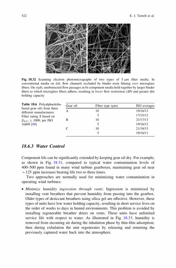
18.6.3 Water Control
Component life can be significantly extended by keeping gear oil dry. For example,as shown in Fig. 18.31, compared to typical water contamination levels of400–500 ppm found in many wind turbine gearboxes, maintaining gear oil near*125 ppm increases bearing life two to three times.
Two approaches are normally used for minimizing water contamination inoperating wind turbines:
• Minimize humidity ingression through vents: Ingression is minimized byinstalling vent breathers that prevent humidity from passing into the gearbox.Older types of desiccant breathers using silica gel are effective. However, thesetypes of units have low water holding capacity, resulting in short service lives onthe order of weeks to days in humid environments. This problem is avoided byinstalling regenerable breather driers on vents. These units have unlimitedservice life with respect to water. As illustrated in Fig. 18.33, humidity isremoved from incoming air during the inhalation phase by thin-film adsorption;then during exhalation the unit regenerates by releasing and returning thepreviously captured water back into the atmosphere.
Fig. 18.32 Scanning electron photomicrographs of two types of 5 lm filter media. Inconventional media on left, flow channels occluded by binder resin filming over microglassfibers. On right, unobstructed flow passages in bi-component media held together by larger binderfibers to which microglass fibers adhere, resulting in lower flow restriction (DP) and greater dirtholding capacity
Table 18.6 Polyalphaolefin-based gear oils from threedifferent manufacturers.Filter rating X based onbX(C) C 1000, per ISO16899 [99]
Gear oil Filter type (lm) ISO averages
A 10 19/16/135 17/15/12
B 10 21/17/135 19/16/12
C 10 21/18/135 19/16/11
522 E. J. Terrell et al.

Water may also enter wind turbine gearboxes during maintenance activities orthrough external seals. A recommended practice for removing this water is toinstall a water absorbing cartridge in the off-line position. Externally these unitsappear similar to particle filters, but inside have quite different constructions. Someare made from porous cellulose-based materials with limited rates of removal andwater holding capacity. Preferred units incorporate super-absorbent polymers(SAP) with 95% water removal efficiency that rapidly take out free water and alsoa portion of the dissolved water, as shown in Fig. 18.34.
Fig. 18.33 The regenerable breather dryer (inset) contains a thin film of adsorbent distributedover a large porous surface area, as well as a fine air particle filter. During inhalation water vaporand airborne particles are removed and prevented from entering the system. During start-up airwarms inside the reservoir, reducing its relative humidity. During exhalation water vapor retainedby the thin film desorbs back into the warmed air and passes back to the environment [100]
Fig. 18.34 At time zeroemulsified water injected intooil to 11,000 ppm (1.1%) freewater concentration. Oil thenrecirculated through a singlewater absorbing cartridge at aturnover rate of 1 every6 min. All free waterremoved in 12 turnovers.Saturation level of dissolvewater in this oil = 200 ppm.(Turnover rate = fluidvolume/flow rate)
18 Wind Turbine Tribology 523

Finally, a proven technology known as dry air blankets has recently beenadapted to wind turbines for water contamination removal. In this system, com-pressed air passes through a pressure swing absorber producing very dry air(-40�C dew point). Flow is arranged so that a blanket of the dry air sweeps overthe oil surface in the reservoir. Gear oil is continuously dehumidified by contactingthe dry air, as shown in Fig. 18.35. Slight pressurization of the system also inhibitsingression of humid air. Thus dry air blankets minimize water ingression andsimultaneously remove water from gearboxes.
18.7 Condition Monitoring
Wind turbine condition monitoring systems allow early warnings of mechanicaland electrical faults, which allow the operator to plan system repair before severefailure takes place [101]. Because early damage to components can oftentimes bedetected while the turbine is still operational, repair work can be planned well inadvance. This is considered to be of importance particularly in regard to offshorewind turbines, where bad weather conditions can prevent repair actions for severalweeks [3]. Typical wind turbine sensors include those for measuring the following:(1) rotor position and speed, (2) generator position and speed, (3) power output,
Fig. 18.35 Drying oil with adry air blanket. Low flow ofvery dry air (-40�C dewpoint) sweeps over surface ofoil in reservoir, bringing oilto less than 20% saturation(\100 ppm for most gearoils). Values on graphindicate the number ofheadspace turnovers per hour[100]
524 E. J. Terrell et al.
(4) tower vibrations and deflections, (5) blade deformations, and (6) controllerinputs such as pitch and yaw settings [102].
Condition monitoring can be performed in one of two ways, namely:
• Offline: Not to be confused with offline filtration as described in Sect. 18.6.2, thismethod involves periodic inspections that require the turbine to be shut down,and may also require the attention of an operator. This method may alsoincorporate the use of diagnostic equipment.
• Online: This method involves the use of automated sensory equipment thatmonitor the components in the turbine continuously during operation. Thesystem may report raw measurements (stress, deflection, etc.), or may alsoincorporate processing systems for data analysis.
Condition monitoring techniques that pertain to the tribological condition of thesystem, namely vibration analysis and oil analysis, are described in the followingsections.
18.7.1 Vibration Analysis
Vibration sensing is one of the most well-known methods for monitoring thecondition of gears and bearings. The sensors that are commonly used depend onthe frequency range that is to be measured, according to the following:
• Position transducers for monitoring low-frequency vibrations• Velocity transducers for monitoring middle-frequency vibrations• Accelerometers for monitoring high-frequency vibrations• Spectral emitted energy (SEE) sensors for very high-frequency vibrations
Additionally, specialized offline acoustic monitoring can be used to determinethe presence of cracks or defects in wind turbine components. Monitoring of thissort involves the attachment of acoustic sensors directly onto the component usingglue with low attenuation, which then monitor the acoustic frequency of thecomponent. The monitoring can take place either passively (i.e., the excitation isgenerated by the component itself), or actively (i.e., the excitation is externallyapplied).
18.7.2 Oil Analysis
Oil analysis can provide information about the health of gears and bearings,as well as detect the presence of particulate or water contamination. For turbinesthat are monitored offline, experience has shown that oil analysis should beperformed after every 4,000 h of operation. After taking a sample of oil from thegearbox, analyses that are commonly performed include:
18 Wind Turbine Tribology 525

• Oxidation: By analyzing the visual appearance of the used lubricant, one candetermine whether it is oxidized. Ideally, the lubricant should appear clear andbright; lubricant-darkened colors may indicate oxidation. Also, the odor oflubricant can be analyzed, in that a sour, pungent, or ‘‘burnt’’ smell indicates thatoxidation has taken place. Finally, a measure of the lubricant viscosity mayallow for the determination of oxidation, as an increase in viscosity over that offresh oil can be caused by oxidative effects.
• Water Content: Water contamination can be determined by a crackle test(i.e., placing the oil on a hot plate to determine the degree of bubble formation),or by more sophisticated methods, such as distillation, infrared, and Karl Fischeranalysis.
• Particulate Contamination: Similar to the oxidation test, the visual appearanceof lubricant (i.e., darkened colors), as well as an increase in the lubricant vis-cosity, may also indicate particulate contamination. More sophisticated methodssuch as spectrochemical analysis and automatic particle counting can providesignificant details as to the size and composition of contaminants.
Although offline oil analysis is frequently used, an increasing number of windturbine systems are being equipped with online oil monitoring systems whichprovide continuous monitoring of a small fraction of the lubricant. These systemsmay rely on optical, electromagnetic, or other physical principles to sense thedegree of particle contamination. It must also be noted that a specialized class oflubricant monitoring, denoted as inline monitoring systems, involves the moni-toring of all of the circulating fluid [57].
18.8 Closure
Wind turbine designs have evolved significantly since their inception and allindications point to continued growth in both installation rate and technologicaldevelopment. Wind turbines incorporate a number of tribological systems,including low-speed, intermediate-speed, and high-speed drivetrain gears andbearings, oscillatory pitch and yaw bearings, and a mechanical brake. As increas-ingly powerful wind turbines have been designed over the years, more attention hasbeen paid towards solving the tribological challenges in wind turbine systems,although many challenges remain. In particular, advanced filtration technology is ofupmost importance, as clean lubricant is crucial towards maximizing the lifetime ofcritical drivetrain components. It is also important to have a detailed understandingof the loads that are being applied to wind turbine tribological systems. Having thisknowledge will aid in the selection of the most appropriate tribological componentfor each section of the turbine, and will also allow for reasonable estimations of thefailure lifetime of each component. Finally, condition monitoring is important formonitoring the health of tribological components.
Wind turbine manufacturers are trending towards developing wind turbines ofincreasingly larger size and power capacity. This is especially the case for offshore
526 E. J. Terrell et al.

wind turbine power plants where the wind loads are complex and highly variable. Toensure the reliability of extra-large-scale turbines, it is important to have robust designsof the tribological systems as well as sufficient filtration and online condition moni-toring to make the system less reliant on routine checkups and maintenance.
References
1. B.C. Babu, K.B. Mohanty, Doubly-fed induction generator for variable speed wind energyconversion systems–modeling and simulation. Int. J. Comput. Electr. Eng. 2(1), 141–147(2010)
2. H. Chandler (ed.), Wind Energy–The Facts, in European Wind Energy Association (2003)3. Y. Amirat, M.E.H. Benbouzid, B. Bensaker, R. Wamkeue, Condition Monitoring and ault
Diagnosis in Wind Energy Conversion Systems: A Review in Electric Machines and DrivesConference. IEMDC ‘07, IEEE International, 2007
4. Global Wind 2009 Report, Global Wind Energy Council, 20105. 20% Wind Energy by 2030, U.S. Department of Energy Technical Report, 20086. Strategic research agenda: market deployment strategy from 2008 to 2030, European Wind
Energy Technology Platform, 20087. Mid and long range plan for renewable energy development, Chinese Committee for
National Development and Reform, 20078. B. Lu, Y. Li, X. Wu, Z. Yang, in A review of recent advances in wind turbine condition
monitoring and fault diagnosis (Power Electronics and Machines in Wind Applications,PEMWA, IEEE, 2009), pp. 1–7
9. 2009 wind technologies market report, U.S. Department of Energy, 201010. J. Ribrant, L. Bertling, Survey of failures in wind power systems with focus on Swedish wind
power plants during 1997–2005. IEEE Power Engineering Society General Meeting, 200711. E.J. Terrell, W.M. Needelman, J.K. Kyle, Current and future tribological challenges in wind
turbine power systems, in STLE/ASME international joint tribology conference, ASMEIJTC2009-15220, 2009
12. Wind Energy Siting Handbook, American Wind Energy Association, 200813. L. Mumper, Wind turbine technology turns on bearings and condition monitoring. Utilities
Manager, 200614. M. Islam, D.S.K. Ting, A. Fartaj, Aerodynamic models for Darrieus-type straight-bladed
vertical axis wind turbines. Renew. Sustain. Energy Rev. 12(4), 1087–1109 (2008)15. A.C. Hansen, C.P. Butterfield, Aerodynamics of horizontal-axis wind turbines. Annu. Rev.
Fluid Mech. 25(1), 115–149 (1993)16. S. Oerlemans, P. Sijtsma, B. Méndez López, Location and quantification of noise sources on
a wind turbine. J. Sound Vib. 299(4–5), 869–883 (2007)17. A.D. Hansen, L.H. Hansen, Wind turbine concept market penetration over 10 years
(1995–2004). Wind Energy 10, 81–97 (2007)18. L.H. Hansen, L. Helle, F. Blaabjerg, E. Ritchie, S. Munk-Nielsen, H. Binder, P. Soerensen,
B. Bak-Jensen, Conceptual survey of generators and power electronics for wind turbines.Riso National Lab Technical Report, 2001
19. T. Burton, D. Sharpe, N. Jenkins, E. Bossanyi, Wind Energy (Wiley, NY, 2001)20. A. Petersson, Analysis, modeling and control of doubly-fed induction generators for wind
turbines, in Department of Energy and Environment, Chalmers University of Technology, 200521. H. Li, Z. Chen, Overview of different wind generator systems and their comparisons.
Renew. Power Gener. IET 2(2), 123–138 (2008)22. H. Polinder, F.F.A. van der Pijl, G.J. de Vilder, P.J. Tavner, Comparison of direct-drive
and geared generator concepts for wind turbines. Energy conversion. IEEE Trans 21(3),725–733 (2006)
18 Wind Turbine Tribology 527
23. G.L. Johnson, Wind Energy Systems (Prentice-Hall, Englewood Cliffs, 1985)24. D.S. Zinger, E. Muljadi, Annualized wind energy improvement using variable speeds. IEEE
Trans. Indus. Appl. 33(6), 1444–1447 (1997)25. S.A. Akdag, Ö. Güler, Comparison of wind turbine power curve Models, in International
Renewable Energy Congress, Sousse, Tunisia, 201026. C. Zhe, J.M. Guerrero, F. Blaabjerg, A review of the state of the art of power electronics for
wind turbines. Power Electron. IEEE Trans. 24(8), 1859–1875 (2009)27. J. Peeters, Simulation of Drive Train Loads in a Wind Turbine (Katholieke Universiteit
Leuven, Lueven, 2006)28. E. Hau, Wind Turbines (Springer-Verlag, Berlin, 2006)29. W. Musial, S. Butterfield, B. McNiff, Improving wind turbine gearbox reliability, in
Proceedings of the European Wind Energy Conference, Milan, Italy, 200730. H. Slootweg, E. De Vries, Inside wind turbines-fixed vs variable speed. Renew. Energy
World 6(1), 3041 (2003)31. American Gear Manufacturer’s Association, Standard for design and specification of
gearboxes for wind turbines, ANSI/AGMA/AWEA 6006-A03, 200432. H. Stiesdal, The Wind Turbine Components and Operation (Bonus-Info, Denmark, 1999)33. K.L. Johnson, Contact Mechanics (Cambridge University Press, Cambridge, 1985)34. D.H. Buckley, Surface Effects in Adhesion, Friction, Wear, and Lubrication (Elsevier,
Amsterdam, 1981)35. M.N. Kotzalas, G.L. Doll, Tribological advancements for reliable wind turbine perfor-
mance. Philos. Trans. Royal Soc. A: Math. Phys. Eng. Sci. 368(1929), 4829–4850 (2010)36. T.A. Harris, M.N. Kotzalas, Essential Concepts of Bearing Technology (Taylor and Francis,
Boca Raton, 2007)37. K. Iso, A. Yokouchi, H. Takemura, Research work for clarifying the mechanism of white
structure flaking and extending the life of bearings. in SAE Technical Paper 2005-01-1868,Society of Automotive Engineers, 2005
38. M. Kohara, T. Kawamura, M. Egami, Study on mechanism of hydrogen generation fromlubricants. Tribol. Trans. 46, 5360 (2006)
39. A.V. Olver, The mechanism of rolling contact fatigue: an update. J. Eng. Tribol. 219(5),313–330 (2005)
40. G. Lundberg, A.Z. Palmgren, Dynamic capacity of rolling bearings. Proc. R. Swed. Acad.Eng. Sci. 196, 50 (1947)
41. E.V. Zaretsky, Palmgren revisited–a basis for bearing life prediction. Lubr. Eng. 54, 1823(1998)
42. F.T. Barwell, Report on papers in Session 3 (lubrication), in Proceedings of theInternational Conference on Gearing (1958), pp. 23–25
43. D. Dowson, G.R. Higginson, Elastohydrodyanmic Lubrication, 2nd edn. (1977)44. A.N. Grubin, Investigation of the Contact of Machine Components (Central Scientific
Research Institute for Technology and Mechanics, Moscow, 1949), Book 3045. R.D. Britton, C.D. Elcoate, M.P. Alanou, H.P. Evans, R.W. Snidle, Effect of surface finish
on gear tooth friction. J. Tribol. 122(1), 354–360 (2000)46. A.N. Grubin, Fundamentals of the hydrodynamic theory of lubrication of heavily loaded
cylindrical surfaces. Investigation of the Contact Machine Components, No. 30, 115–166 (1949)47. D. Dowson, G.R. Higginson, A numerical solution to the elasto-hydrodynamic problem.
J. Mech. Eng. Sci. 1(1), 6–15 (1959)48. D. Dowson, G.R. Higginson, Elastohydrodynamic Lubrication (Pergamon Press, Oxford,
1977)49. S. Li, A. Kahraman, Prediction of spur gear mechanical power losses using a transient
elastohydrodynamic lubrication model. Tribol. Trans. 53, 554–563 (2010)50. R. Gohar, Elastohydrodynamics (Wiley, New York, 1988)51. R. Errichello, Friction, lubrication, and wear of gears, in ASM Handbook Friction,
Lubrication, and Wear Technology, vol. 18, ed. by P. Blau (ASM International, MaterialsPark, Ohio, 1992), pp. 535–545
528 E. J. Terrell et al.

52. T.E. Tallian, Simplified contact fatigue life prediction model–part I: review of publishedmodels. J. Tribol. 114(2), 207–213 (1992)
53. G. Stachowiak, A.W. Batchelor, Engineering Tribology (Elsevier, Oxford, 2005)54. G.L. Doll, B.K. Osborn, Engineering surfaces of precision steel components. Proc. Annu.
Tech. Conf. Soc. Vac. Coaters 44, 78–84 (2001)55. G.L. Doll, C.R. Ribaudo, R.D. Evans, Engineered surfaces for steel rolling element bearings
and gears. Mater. Sci. Technol. 2, 367–374 (2004)56. A. Ragheb, M. Ragheb, Wind turbine gearbox technologies, in International Nuclear and
Renewable Energy Conference (INREC10) (Amman, Jordan, 2010)57. R.W. Hyers, J.G. Mcgowan, K.L. Sullivan, J.F. Manwell, B.C. Syrett, Condition monitoring
and prognosis of utility scale wind turbines. Energy Mater.: Mater. Sci. Eng. Energy Syst.1(3), 187–203 (2006)
58. F.L. Litvin, A. Fuentes, Gear Geometry Applied Theory (Cambridge University Press,Cambridge, 2004)
59. J.E. higley, Mechanical Engineering Design (McGraw-Hill, New York, 1963)60. P. Lynwander, Gear Drive Systems: Design and Application (Marcel Dekker, NY, 1983)61. F.L. Litvin, A. Fuentes, I. Gonzalez-Perez, L. Carvenali, K. Kawasaki, R.F. Handschuh,
Modified involute helical gears: computerized design simulation of meshing and stressanalysis. Comput. Methods Appl. Mech. Eng. 192(33–34), 3619–3655 (2003)
62. J. Kleemola, A. Lehtovaara, Experimental simulation of gear contact along the line ofaction. Tribol. Int. 42, 1453–1459 (2009)
63. G.M. Maitra, Handbook of Gear Design (Tata McGraw-Hill, New Delhi, 1997)64. A.H. Elkholy, Tooth load sharing in high contact ratio spur gears. J. Mech. Trans. Autom.
Des. 107(1), 11–16 (1985)65. S. Avinash, Application of a system level model to study the planetary load sharing
behavior. J. Mech. Des. 127(3), 469–476 (2005)66. C.R.M. Rao, G. Muthuveerappan, Finite element modelling and stress analysis of helical
gear teeth. Comput. Struct. 49(6), 1095–1106 (1993)67. B.R. Hohn, K. Michaelis, Influence of oil temperature on gear failures. Tribol. Int. 37(2),
103–109 (2004)68. H. Blok, Les temperatures de surface dans les conditions de graissage sons pression
extreme, in Second World Petroleum Congress, Paris, 193769. E.E. Shipley, Failure analysis of coarse-pitch, hardened, and ground gears. Paper No.
P229.26, (American Gear Manufacturers Association, Alexandria, 1982), pp. 1–2470. S. Tanaka, Appreciable increases in surface durability of gear pairs with mirror-like finish,
Paper No. 84-DET-223, (American Society of Mechanical Engineers, Alexandria, 1984),pp. 1–8
71. X. Ai, Effect of debris contamination on the fatigue life of roller bearings. Proc. Inst. Mech.Eng. Part J: J. Eng. Tribol. 215(6), 563–575 (2001)
72. I. Allison, E. Hearn, A new look at the bending strength of gear teeth. Exp. Mech. 20(7),217–225 (1980)
73. J. Hiremagalur, B. Ravani, Effect of backup ratio on root stresses in spur gear design. Mech.Based Des. Struct. Mach.: Int. J. 32(4), 423–440 (2004)
74. W. Lewis, Investigation of the strength of gear teeth, in Proceedings of EngineersClub(1892), pp. 16–23
75. T.J. Dolan, E.L. Broghamer, A photoelastic study of stresses in gear tooth fillets. Universityof Illinois Bulletin, vol 355 (1942)
76. B.W. Kelley, R. Pedersen, The beam strength of modern gear tooth design. Transactions ofthe S.A.E., 1957
77. X.Q. Peng, L. Geng, W. Liyan, G.R. Liu, K.Y. Lam, A stochastic finite element methodfor fatigue reliability analysis of gear teeth subjected to bending. Comput. Mech. 21(3),253–261 (1998)
78. J.D. Andrews, A finite element analysis of bending stresses induced in external and internalinvolute spur gears. J. Strain Anal. Eng. Des. 26(3), 153–163 (1991)
18 Wind Turbine Tribology 529
79. M.A. Miner, Cumulative damage in fatigue. J. Appl. Mech. 67, A159–A164 (1945)80. A.Z. Palmgren, Die Lebensdauer von Kugelagern. 2 ver Deutsch Ing 68, 339–341 (1924)81. T.A. Harris, J.H. Rumbarger, C.P. Butterfield, Wind turbine design guideline DG03: yaw
and pitch rolling bearing life, NREL Technical Report No. NREL/TP-500-42362, 200982. T. Senjyu, R. Sakamoto, N. Urasaki, T. Funabashi, H. Fujita, H. Sekine, Output power
leveling of wind turbine generator for all operating regions by pitch angle control. IEEETrans. Energy Convers. 21(2), 467–475 (2006)
83. J. Aguirrebeitia, R. Aviles, I.F.d. Bustos, M. Abasolo, Calculation of general static load-carrying capacity for the design of four-contact-point slewing bearings. J. Mech. Des.132(6), P064501 (2010)
84. W.J. Bartz, Tribological aspects of wind power plants, in Proceedings of the WorldTribology Congress III, Washington, D.C., USA, 2005
85. J.C. Enthoven, H.A. Spikes, Visual observation of the process of scuffing, in Lubricantsand Lubrication, Proceedings of the 21st Leeds-Lyon Symposium on Tribology (1995),pp. 487–494
86. G.K. Nikas, R.S. Sayles, E. Ioannides, Effects of debris particles in sliding/rollingelastohydrodynamic contacts. J. Eng. Tribol. 212(5), 333–343 (1998)
87. G. Xu, F. Sadeghi, J.D. Cogdell, Debris denting effects on elastrohydrodynamic lubricatedcontacts. Trans. ASME J. Tribol. 119, 579–587 (1997)
88. X. Ai, H.S. Cheng, The influence of moving dent on point EHL contacts. Tribol. Trans.37(2), 323–335 (1994)
89. S. Butterfield, R. Errichello, B. McNiff, Wind turbine gearbox issues and lubrication, inIJTC2008-71361, 2008
90. M.N. Kotzalas, W.M. Needelman, D.R. Lucas, G.L. LaVallee, Improving wind turbinegearbox life, in AWEA Windpower Conference, Houston, 2008
91. R.E. Cantley, The effect of water in lubricating oil on bearing fatigue life. ASLE Trans.20(3), 244–248 (1977)
92. E.V. Zaretsky (ed.), Life Factors for Rolling Bearings (Society of Tribologists andLubrication Engineers, Park Ridge, 1992)
93. E. Abner, in Handbook of Lubrication, ed. by E.R. Booser, Lubricant deterioration inservice (CRC Press, Boca Raton, 1983)
94. W.M. Needelman, M.A. Barris, and G.L. LaVallee, Contamination Control for WindTurbine Gearboxes. Power Engineering
95. Hydraulic fluid power—Filters—Multi-pass method for evaluating filtration performance ofa filter element. ISO 16889. 2008: International Organization for Standardization
96. W.M. Needelman, M.A. Barris and G.L. LaVallee, Contamination control for wind turbinegearboxes. Power Engineering, 2009
97. W.M. Needelman, E.V. Zaretsky, New equations show oil filtration effect on bearing life.Power Transm. Des. 33(8), 65–68 (1991)
98. W.M. Needelman, E.V. Zaretsky, Recalibrated equations for determining effect of oilfiltration on rolling bearing life, in STLE Annual Meeting, Orlando (2009)
99. W.M. Needelman, M.A. Barris, G.L. LaVallee, Reducing cost of operation in harshconditions with new generation filters, in International Fluid Power Exposition, Las Vegas(2011)
100. G.L. LaVallee, W.M. Needelman, Dry air blankets: An effective and economical method foreradicating water contamination. Part I: principles of operation, in STLE Annual Meeting,Las Vegas (2010)
101. C.S. Gray, S.J. Watson, Physics of failure approach to wind turbine condition basedmaintenance. Wind Energy 13(5), 395–405 (2010)
102. Z. Hameed, Y.S. Hong, Y.M. Cho, S.H. Ahn, C.K. Song, Condition moitoring and faultdetection of wind turbines and related algorithms: a review. Renew. Sustain. Energy Rev.13(1), 1–39 (2009)
530 E. J. Terrell et al.