CHAPTER 17 FABRICATION AND PROCESSING OF...
63
Excerpts from this work may be reproduced by instructors for distribution on a not-for-profit basis for testing or instructional purposes only to students enrolled in courses for which the textbook has been adopted. Any other reproduction or translation of this work beyond that permitted by Sections 107 or 108 of the 1976 United States Copyright Act without the permission of the copyright owner is unlawful. CHAPTER 17 FABRICATION AND PROCESSING OF ENGINEERING MATERIALS PROBLEM SOLUTIONS Forming Operations 17.1 Cite advantages and disadvantages of hot working and cold working. Solution The advantages of cold working are: (1) A high quality surface finish. (2) The mechanical properties may be varied. (3) Close dimensional tolerances. The disadvantages of cold working are: (1) High deformation energy requirements. (2) Large deformations must be accomplished in steps, which may be expensive. (3) A loss of ductility. The advantages of hot working are: (1) Large deformations are possible, which may be repeated. (2) Deformation energy requirements are relatively low. The disadvantages of hot working are: (1) A poor surface finish. (2) A variety of mechanical properties is not possible.
Transcript of CHAPTER 17 FABRICATION AND PROCESSING OF...
Excerpts from this work may be reproduced by instructors for distribution on a not-for-profit basis for testing or instructional purposes only to students enrolled in courses for which the textbook has been adopted. Any other reproduction or translation of
this work beyond that permitted by Sections 107 or 108 of the 1976 United States Copyright Act without the permission of the
copyright owner is unlawful.
CHAPTER 17
FABRICATION AND PROCESSING OF ENGINEERING MATERIALS
PROBLEM SOLUTIONS
Forming Operations
17.1 Cite advantages and disadvantages of hot working and cold working.
Solution
The advantages of cold working are:
(1) A high quality surface finish.
(2) The mechanical properties may be varied.
(3) Close dimensional tolerances.
The disadvantages of cold working are:
(1) High deformation energy requirements.
(2) Large deformations must be accomplished in steps, which may be expensive.
(3) A loss of ductility.
The advantages of hot working are:
(1) Large deformations are possible, which may be repeated.
(2) Deformation energy requirements are relatively low.
The disadvantages of hot working are:
(1) A poor surface finish.
(2) A variety of mechanical properties is not possible.
Excerpts from this work may be reproduced by instructors for distribution on a not-for-profit basis for testing or instructional purposes only to students enrolled in courses for which the textbook has been adopted. Any other reproduction or translation of
this work beyond that permitted by Sections 107 or 108 of the 1976 United States Copyright Act without the permission of the
copyright owner is unlawful.
17.2 (a) Cite advantages of forming metals by extrusion as opposed to rolling. (b) Cite some
disadvantages.
Solution
(a) The advantages of extrusion as opposed to rolling are as follows:
(1) Pieces having more complicated cross-sectional geometries may be formed.
(2) Seamless tubing may be produced.
(b) The disadvantages of extrusion over rolling are as follows:
(1) Nonuniform deformation over the cross-section.
(2) A variation in properties may result over a cross-section of an extruded piece.
Excerpts from this work may be reproduced by instructors for distribution on a not-for-profit basis for testing or instructional purposes only to students enrolled in courses for which the textbook has been adopted. Any other reproduction or translation of
this work beyond that permitted by Sections 107 or 108 of the 1976 United States Copyright Act without the permission of the
copyright owner is unlawful.
Casting
17.3 List four situations in which casting is the preferred fabrication technique.
Solution
Four situations in which casting is the preferred fabrication technique are:
(1) For large pieces and/or complicated shapes.
(2) When mechanical strength is not an important consideration.
(3) For alloys having low ductilities.
(4) When it is the most economical fabrication technique.
Excerpts from this work may be reproduced by instructors for distribution on a not-for-profit basis for testing or instructional purposes only to students enrolled in courses for which the textbook has been adopted. Any other reproduction or translation of
this work beyond that permitted by Sections 107 or 108 of the 1976 United States Copyright Act without the permission of the
copyright owner is unlawful.
17.4 Compare sand, die, investment, lost foam, and continuous casting techniques.
Solution
For sand casting, sand is the mold material, a two-piece mold is used, ordinarily the surface
finish is not an important consideration, the sand may be reused (but the mold may not), casting rates
are low, and large pieces are usually cast.
For die casting, a permanent mold is used, casting rates are high, the molten metal is forced
into the mold under pressure, a two-piece mold is used, and small pieces are normally cast.
For investment casting, a single-piece mold is used, which is not reusable; it results in high
dimensional accuracy, good reproduction of detail, and a fine surface finish; and casting rates are low.
For lost foam casting, the pattern is polystyrene foam, whereas the mold material is sand.
Complex geometries and tight tolerances are possible. Casting rates are higher than for investment,
and there are few environmental wastes.
For continuous casting, at the conclusion of the extraction process, the molten metal is cast
into a continuous strand having either a rectangular or circular cross-section; these shapes are desirable
for subsequent secondary metal-forming operations. The chemical composition and mechanical
properties are relatively uniform throughout the cross-section.
Excerpts from this work may be reproduced by instructors for distribution on a not-for-profit basis for testing or instructional purposes only to students enrolled in courses for which the textbook has been adopted. Any other reproduction or translation of
this work beyond that permitted by Sections 107 or 108 of the 1976 United States Copyright Act without the permission of the
copyright owner is unlawful.
Miscellaneous Techniques
17.5 If it is assumed that, for steel alloys, the average cooling rate of the heat-affected zone in the
vicinity of a weld is 10°C/s, compare the microstructures and associated properties that will
result for 1080 (eutectoid) and 4340 alloys in their HAZs.
Solution
This problem asks that we specify and compare the microstructures and mechanical properties
in the heat-affected weld zones for 1080 and 4340 alloys assuming that the average cooling rate is
10C/s. Figure 12.27 shows the continuous cooling transformation diagram for an iron–carbon alloy of
eutectoid composition (1080), and, in addition, cooling curves that delineate changes in microstructure.
For a cooling rate of 10C/s (which is less than 35C/s) the resulting microstructure will be totally
pearlite—probably a reasonably fine pearlite. On the other hand, in Figure 12.28 is shown the CCT
diagram for a 4340 steel. From this diagram it may be noted that a cooling rate of 10C/s produces a
totally martensitic structure. Pearlite is softer and more ductile than martensite, and, therefore, is most
likely more desirable.

Excerpts from this work may be reproduced by instructors for distribution on a not-for-profit basis for testing or instructional purposes only to students enrolled in courses for which the textbook has been adopted. Any other reproduction or translation of
this work beyond that permitted by Sections 107 or 108 of the 1976 United States Copyright Act without the permission of the
copyright owner is unlawful.
17.6 Describe one problem that might exist with a steel weld that was cooled very rapidly.
Solution
If a steel weld is cooled very rapidly, martensite may form, which is very brittle. In some
situations, cracks may form in the weld region as it cools.
Excerpts from this work may be reproduced by instructors for distribution on a not-for-profit basis for testing or instructional purposes only to students enrolled in courses for which the textbook has been adopted. Any other reproduction or translation of
this work beyond that permitted by Sections 107 or 108 of the 1976 United States Copyright Act without the permission of the
copyright owner is unlawful.
Annealing Processes
17.7 In your own words describe the following heat treatment procedures for steels and, for each, the
intended final microstructure: full annealing, normalizing, quenching, and tempering.
Solution
Full annealing—Heat to about 50C (323 K) above the A3 line, Figure 17.4 (if the
concentration of carbon is less than the eutectoid) or above the A1 line (if the concentration of carbon is
greater than the eutectoid) until the alloy comes to equilibrium; then furnace cool to room temperature.
The final microstructure is coarse pearlite.
Normalizing—Heat to at least 55C (328 K) above the A3 line Figure 17.4 (if the
concentration of carbon is less than the eutectoid) or above the Acm line (if the concentration of carbon
is greater than the eutectoid) until the alloy completely transforms to austenite, then cool in air. The
final microstructure is fine pearlite.
Quenching—Heat to a temperature within the austenite phase region and allow the specimen
to fully austenitize, then quench to room temperature in oil or water. The final microstructure is
martensite.
Tempering—Heat a quenched (martensitic) specimen, to a temperature between 450 and
650C (723 and 923 K), for the time necessary to achieve the desired hardness. The final
microstructure is tempered martensite.
Excerpts from this work may be reproduced by instructors for distribution on a not-for-profit basis for testing or instructional purposes only to students enrolled in courses for which the textbook has been adopted. Any other reproduction or translation of
this work beyond that permitted by Sections 107 or 108 of the 1976 United States Copyright Act without the permission of the
copyright owner is unlawful.
17.8 Cite three sources of internal residual stresses in metal components. What are two possible
adverse consequences of these stresses?
Solution
Three sources of residual stresses in metal components are plastic deformation processes,
nonuniform cooling of a piece that was cooled from an elevated temperature, and a phase
transformation in which parent and product phases have different densities.
Two adverse consequences of these stresses are distortion (or warpage) and fracture.

Excerpts from this work may be reproduced by instructors for distribution on a not-for-profit basis for testing or instructional purposes only to students enrolled in courses for which the textbook has been adopted. Any other reproduction or translation of
this work beyond that permitted by Sections 107 or 108 of the 1976 United States Copyright Act without the permission of the
copyright owner is unlawful.
17.9 Give the approximate minimum temperature at which it is possible to austenitize each of the
following iron–carbon alloys during a normalizing heat treatment: (a) 0.25 wt% C, (b) 0.75 wt%
C, and (c) 0.90 wt% C.
Solution
(a) For 0.25 wt% C, heat to at least 885C (1158 K) since the A3 temperature is 830C (1103 K).
(b) For 0.75 wt% C, heat to at least 790C (1063 K) since the A3 temperature is 735C (1008 K).
(c) For 0.90 wt% C, heat to at least 820C (1093 K) since the Acm temperature is 765C (1038 K).

Excerpts from this work may be reproduced by instructors for distribution on a not-for-profit basis for testing or instructional purposes only to students enrolled in courses for which the textbook has been adopted. Any other reproduction or translation of
this work beyond that permitted by Sections 107 or 108 of the 1976 United States Copyright Act without the permission of the
copyright owner is unlawful.
17.10 Give the approximate temperature at which it is desirable to heat each of the following iron–
carbon alloys during a full anneal heat treatment: (a) 0.20 wt% C, (b) 0.50 wt% C, (c) 0.80 wt%
C, and (d) 1.15 wt% C.
Solution
(a) For 0.20 wt% C, heat to about 890C (1163 K) since the A3 temperature is 840C (1113 K).
(b) For 0.50 wt% C, heat to about 815C (1088 K) since the A3 temperature is 765C (1038 K).
(c) For 0.80 wt% C, heat to about 775C (1048 K) since the A1 temperature is 725C (998 K).
(d) For 1.15 wt% C, heat to about 775C (1048 K) since the A1 temperature is 725C (998 K).

Excerpts from this work may be reproduced by instructors for distribution on a not-for-profit basis for testing or instructional purposes only to students enrolled in courses for which the textbook has been adopted. Any other reproduction or translation of
this work beyond that permitted by Sections 107 or 108 of the 1976 United States Copyright Act without the permission of the
copyright owner is unlawful.
17.11 What is the purpose of a spheroidizing heat treatment? On what classes of alloys is it normally
used?
Solution
The purpose of a spheroidizing heat treatment is to produce a very soft and ductile steel alloy
having a spheroiditic microstructure. It is normally used on medium- and high-carbon steels, which, by
virtue of carbon content, are relatively hard and strong.

Excerpts from this work may be reproduced by instructors for distribution on a not-for-profit basis for testing or instructional purposes only to students enrolled in courses for which the textbook has been adopted. Any other reproduction or translation of
this work beyond that permitted by Sections 107 or 108 of the 1976 United States Copyright Act without the permission of the
copyright owner is unlawful.
Heat Treatment of Steels
17.12 Briefly explain the difference between hardness and hardenability.
Solution
Hardness is a measure of a material's resistance to localized surface deformation, whereas
hardenability is a measure of the depth to which a ferrous alloy may be hardened by the formation of
martensite. Hardenability is determined from hardness tests.
Excerpts from this work may be reproduced by instructors for distribution on a not-for-profit basis for testing or instructional purposes only to students enrolled in courses for which the textbook has been adopted. Any other reproduction or translation of
this work beyond that permitted by Sections 107 or 108 of the 1976 United States Copyright Act without the permission of the
copyright owner is unlawful.
17.13 What influence does the presence of alloying elements (other than carbon) have on the shape of
a hardenability curve? Briefly explain this effect.
Solution
The presence of alloying elements (other than carbon) causes a much more gradual decrease in
hardness with position from the quenched end for a hardenability curve. The reason for this effect is
that alloying elements retard the formation of pearlitic and bainitic structures which are not as hard as
martensite.

Excerpts from this work may be reproduced by instructors for distribution on a not-for-profit basis for testing or instructional purposes only to students enrolled in courses for which the textbook has been adopted. Any other reproduction or translation of
this work beyond that permitted by Sections 107 or 108 of the 1976 United States Copyright Act without the permission of the
copyright owner is unlawful.
17.14 How would you expect a decrease in the austenite grain size to affect the hardenability of a steel
alloy? Why?
Solution
A decrease of austenite grain size will decrease the hardenability. Pearlite normally nucleates
at grain boundaries, and the smaller the grain size, the greater the grain boundary area, and,
consequently, the easier it is for pearlite to form.

Excerpts from this work may be reproduced by instructors for distribution on a not-for-profit basis for testing or instructional purposes only to students enrolled in courses for which the textbook has been adopted. Any other reproduction or translation of
this work beyond that permitted by Sections 107 or 108 of the 1976 United States Copyright Act without the permission of the
copyright owner is unlawful.
17.15 Name two thermal properties of a liquid medium that will influence its quenching effectiveness.
Solution
The two thermal properties of a liquid medium that influence its quenching effectiveness are
thermal conductivity and heat capacity.

Excerpts from this work may be reproduced by instructors for distribution on a not-for-profit basis for testing or instructional purposes only to students enrolled in courses for which the textbook has been adopted. Any other reproduction or translation of
this work beyond that permitted by Sections 107 or 108 of the 1976 United States Copyright Act without the permission of the
copyright owner is unlawful.
17.16 Construct radial hardness profiles for the following:
(a) A 45-mm diameter cylindrical specimen of an 8640 steel alloy that has been quenched in
moderately agitated oil
Solution
In the manner of Example Problem 17..1, the equivalent distances and hardnesses tabulated
below were determined from Figures 17.8 and 17.11b.
Radial Equivalent HRC Position Distance, mm Hardness
Surface 7 52
3/4 R 11 50
Midradius 14 45
Center 16 44
The resulting hardness profile is plotted below.
(b) A 80-mm diameter cylindrical specimen of a 5140 steel alloy that has been quenched in
moderately agitated oil
Solution
In the manner of Example Problem 17..1, the equivalent distances and hardnesses tabulated
below were determined from Figures 17.8 and 17.11b.

Excerpts from this work may be reproduced by instructors for distribution on a not-for-profit basis for testing or instructional purposes only to students enrolled in courses for which the textbook has been adopted. Any other reproduction or translation of
this work beyond that permitted by Sections 107 or 108 of the 1976 United States Copyright Act without the permission of the
copyright owner is unlawful.
Radial Equivalent HRC Position Distance, mm Hardness
Surface 13 41.5
3/4 R 17.5 37
Midradius 22 33
Center 25 32
The resulting hardness profile is plotted below.
(c) A 60-mm diameter cylindrical specimen of an 8620 steel alloy that has been quenched in
moderately agitated water
Solution
In the manner of Example Problem 17..1, the equivalent distances and hardnesses tabulated
below were determined from Figures 17.9 and 17.11a.
Radial Equivalent HRC Position Distance, mm Hardness
Surface 2.5 37
3/4 R 7 31
Midradius 11 25
Center 13 24
The resulting hardness profile is plotted below.
Excerpts from this work may be reproduced by instructors for distribution on a not-for-profit basis for testing or instructional purposes only to students enrolled in courses for which the textbook has been adopted. Any other reproduction or translation of
this work beyond that permitted by Sections 107 or 108 of the 1976 United States Copyright Act without the permission of the
copyright owner is unlawful.
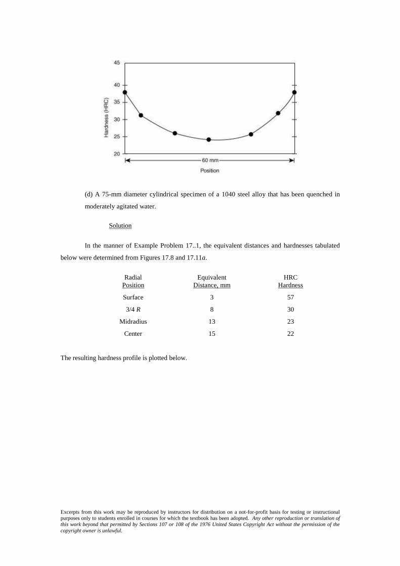
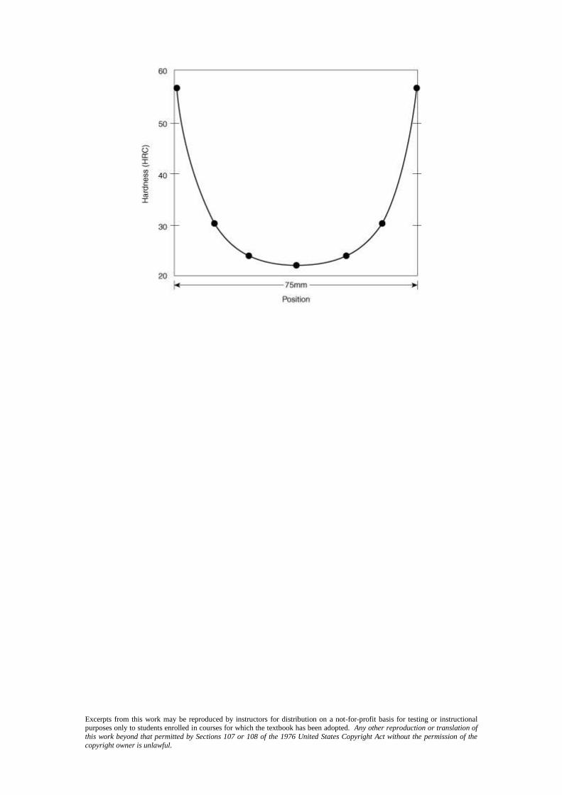
(d) A 75-mm diameter cylindrical specimen of a 1040 steel alloy that has been quenched in
moderately agitated water.
Solution
In the manner of Example Problem 17..1, the equivalent distances and hardnesses tabulated
below were determined from Figures 17.8 and 17.11a.
Radial Equivalent HRC Position Distance, mm Hardness
Surface 3 57
3/4 R 8 30
Midradius 13 23
Center 15 22
The resulting hardness profile is plotted below.
Excerpts from this work may be reproduced by instructors for distribution on a not-for-profit basis for testing or instructional purposes only to students enrolled in courses for which the textbook has been adopted. Any other reproduction or translation of
this work beyond that permitted by Sections 107 or 108 of the 1976 United States Copyright Act without the permission of the
copyright owner is unlawful.
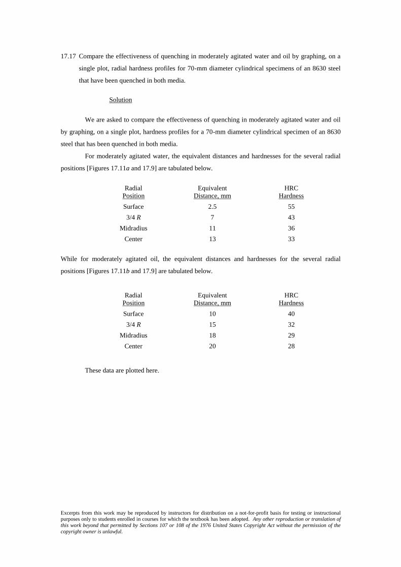
17.17 Compare the effectiveness of quenching in moderately agitated water and oil by graphing, on a
single plot, radial hardness profiles for 70-mm diameter cylindrical specimens of an 8630 steel
that have been quenched in both media.
Solution
We are asked to compare the effectiveness of quenching in moderately agitated water and oil
by graphing, on a single plot, hardness profiles for a 70-mm diameter cylindrical specimen of an 8630
steel that has been quenched in both media.
For moderately agitated water, the equivalent distances and hardnesses for the several radial
positions [Figures 17.11a and 17.9] are tabulated below.
Radial Equivalent HRC
Position Distance, mm Hardness
Surface 2.5 55
3/4 R 7 43
Midradius 11 36
Center 13 33
While for moderately agitated oil, the equivalent distances and hardnesses for the several radial
positions [Figures 17.11b and 17.9] are tabulated below.
Radial Equivalent HRC
Position Distance, mm Hardness
Surface 10 40
3/4 R 15 32
Midradius 18 29
Center 20 28
These data are plotted here.

Excerpts from this work may be reproduced by instructors for distribution on a not-for-profit basis for testing or instructional purposes only to students enrolled in courses for which the textbook has been adopted. Any other reproduction or translation of
this work beyond that permitted by Sections 107 or 108 of the 1976 United States Copyright Act without the permission of the
copyright owner is unlawful.
Precipitation Hardening
17.18 Compare precipitation hardening (Section 17.7) and the hardening of steel by quenching and
tempering (Sections 12.5, 12.6, and 12.8) with regard to
(a) The total heat treatment procedure
(b) The microstructures that develop
(c) How the mechanical properties change during the several heat treatment stages
Solution
(a) With regard to the total heat treatment procedure, the steps for the hardening of steel are as follows:
(1) Austenitize above the upper critical temperature.
(2) Quench to a relatively low temperature.
(3) Temper at a temperature below the eutectoid.
(4) Cool to room temperature.
With regard to precipitation hardening, the steps are as follows:
(1) Solution heat treat by heating into the solid solution phase region.
(2) Quench to a relatively low temperature.
(3) Precipitation-harden by heating to a temperature that is within the solid two-phase region.
(4) Cool to room temperature.
(b) For the hardening of steel, the microstructures that form at the various heat treating stages in part
(a) are:
(1) Austenite
(2) Martensite
(3) Tempered martensite
(4) Tempered martensite
For precipitation hardening, the microstructures that form at the various heat treating stages in part (a)
are:
(1) Single phase
(2) Single phase–supersaturated
(3) Small plate-like particles of a new phase within a matrix of the original phase.
(4) Same as (3)
(c) For the hardening of steel, the mechanical characteristics for the various steps in part (a) are as
follows:
(1) Not important
(2) The steel becomes hard and brittle upon quenching.
(3) During tempering, the alloy softens slightly and becomes more ductile.
(4) No significant changes upon cooling to or maintaining at room temperature.

Excerpts from this work may be reproduced by instructors for distribution on a not-for-profit basis for testing or instructional purposes only to students enrolled in courses for which the textbook has been adopted. Any other reproduction or translation of
this work beyond that permitted by Sections 107 or 108 of the 1976 United States Copyright Act without the permission of the
copyright owner is unlawful.
For precipitation hardening, the mechanical characteristics for the various steps in part (a) are as
follows:
(1) Not important
(2) The alloy is relatively soft.
(3) The alloy hardens with increasing time (initially), and becomes more brittle; it may soften
with overaging.
(4) The alloy may continue to harden or overage at room temperature.

Excerpts from this work may be reproduced by instructors for distribution on a not-for-profit basis for testing or instructional purposes only to students enrolled in courses for which the textbook has been adopted. Any other reproduction or translation of
this work beyond that permitted by Sections 107 or 108 of the 1976 United States Copyright Act without the permission of the
copyright owner is unlawful.
17.19 What is the principal difference between natural and artificial aging processes?
Solution
For precipitation hardening, natural aging is allowing the precipitation process to occur at the
ambient temperature; artificial aging is carried out at an elevated temperature.

Excerpts from this work may be reproduced by instructors for distribution on a not-for-profit basis for testing or instructional purposes only to students enrolled in courses for which the textbook has been adopted. Any other reproduction or translation of
this work beyond that permitted by Sections 107 or 108 of the 1976 United States Copyright Act without the permission of the
copyright owner is unlawful.
Fabrication and Processing of Glasses and Glass-Ceramics
17.20 Soda and lime are added to a glass batch in the form of soda ash (Na2CO3) and limestone
(CaCO3). During heating, these two ingredients decompose to give off carbon dioxide (CO2), the
resulting products being soda and lime. Compute the weight of soda ash and limestone that must
be added to 45.3 kg of quartz (SiO2) to yield a glass of composition 75 wt% SiO2, 20 wt% Na2O,
and 5 wt% CaO.
Solution
We are asked to compute the weight of soda ash and limestone that must be added to 45.3 kg
of SiO2 to yield a glass composition of 75 wt% SiO2, 20 wt% Na2O, and 5 wt% CaO. Let x equal the
weight of Na2O and y equal the weight of CaO. Then, employment of a modified form Equation 6.6,
we may write the following expressions for the concentrations of Na2O (CNa2O) and CaO (CCaO):
2Na O 20 wt% 10045.3
xC
x y
CaO 5 wt% 10045.3
yC
x y
Solving for x and y from these two expressions yields x = 12.08 kg Na2O and y = 3.02 kg CaO.
Now, in order to compute the weights of Na2CO3 and CaCO3, we must employ molecular
weights. The molecular weights of Na2CO3 (MWNa2CO3) and Na2O (MWNa2O) are as follows:
MWNa2CO3= 2(ANa ) + AC + 3(AO)
= 2(22.99 g/mol) + 12.01 g/mol + 3(16.00g/mol) = 105.99 g/mol
MWNa2O = 2(ANa ) + AO
= 2(22.99 g/mol) + 16.00 g/mol = 61.98 g/mol
And, finally, the mass of Na2CO3 (mNa2CO3) is equal to
2 3
2 3
2
Na CO
Na CO
Na
= (12.08 kg)O
MWm
MW
Excerpts from this work may be reproduced by instructors for distribution on a not-for-profit basis for testing or instructional purposes only to students enrolled in courses for which the textbook has been adopted. Any other reproduction or translation of
this work beyond that permitted by Sections 107 or 108 of the 1976 United States Copyright Act without the permission of the
copyright owner is unlawful.
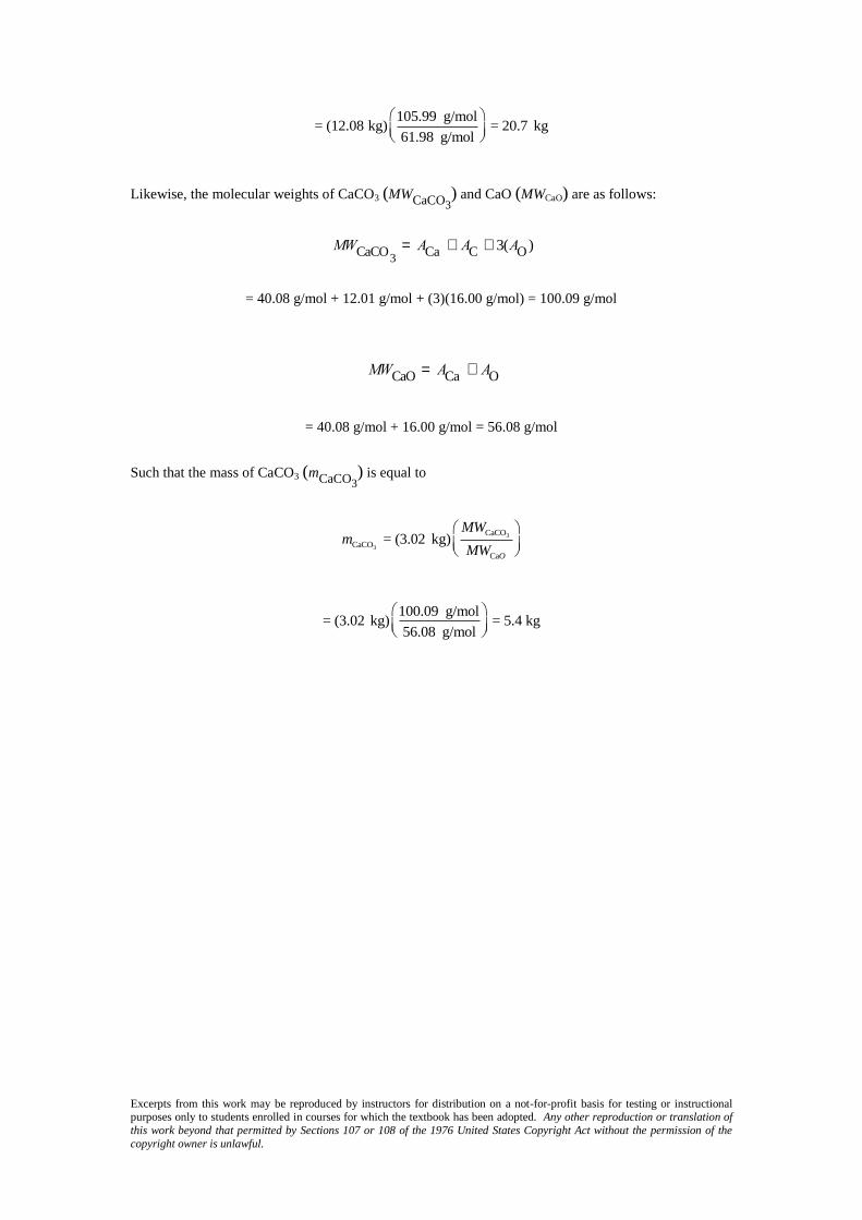
105.99 g/mol= (12.08 kg) = 20.7 kg
61.98 g/mol
Likewise, the molecular weights of CaCO3 (MWCaCO3) and CaO (MWCaO) are as follows:
MWCaCO
3= ACa + AC + 3(AO )
= 40.08 g/mol + 12.01 g/mol + (3)(16.00 g/mol) = 100.09 g/mol
MWCaO = ACa + AO
= 40.08 g/mol + 16.00 g/mol = 56.08 g/mol
Such that the mass of CaCO3 (mCaCO3) is equal to
3
3
CaCO
CaCO
Ca
= (3.02 kg)O
MWm
MW
100.09 g/mol= (3.02 kg) = 5.4 kg
56.08 g/mol

Excerpts from this work may be reproduced by instructors for distribution on a not-for-profit basis for testing or instructional purposes only to students enrolled in courses for which the textbook has been adopted. Any other reproduction or translation of
this work beyond that permitted by Sections 107 or 108 of the 1976 United States Copyright Act without the permission of the
copyright owner is unlawful.
17.21 What is the distinction between glass transition temperature and melting temperature?
Solution
The glass transition temperature is, for a noncrystalline ceramic, that temperature at which
there is a change of slope for the specific volume versus temperature curve (Figure 17.23).
The melting temperature is, for a crystalline material and upon cooling, that temperature at
which there is a sudden and discontinuous decrease in the specific-volume-versus-temperature curve.
Excerpts from this work may be reproduced by instructors for distribution on a not-for-profit basis for testing or instructional purposes only to students enrolled in courses for which the textbook has been adopted. Any other reproduction or translation of
this work beyond that permitted by Sections 107 or 108 of the 1976 United States Copyright Act without the permission of the
copyright owner is unlawful.
17.22 Compare the temperatures at which soda–lime, borosilicate, 96% silica, and fused silica may be
annealed.
Solution
The annealing point is that temperature at which the viscosity of the glass is 1210 Pa s . From
Figure 17.24, these temperatures for the several glasses are as follows:
Glass Annealing Temperature
Soda–lime 500C (773 K)
Borosilicate 565C (835 K)
96% Silica 930C (1203 K)
Fused silica 1170C (1443 K)

Excerpts from this work may be reproduced by instructors for distribution on a not-for-profit basis for testing or instructional purposes only to students enrolled in courses for which the textbook has been adopted. Any other reproduction or translation of
this work beyond that permitted by Sections 107 or 108 of the 1976 United States Copyright Act without the permission of the
copyright owner is unlawful.
17.23 Compare the softening points for 96% silica, borosilicate, and soda–lime glasses.
Solution
The softening point of a glass is that temperature at which the viscosity is 64 10 Pa s ; from
Figure 17.24, these temperatures for the 96% silica, borosilicate, and soda–lime glasses are 1540C
(1813 K), 830C (1103 K), and 700C (973 K), respectively.
Excerpts from this work may be reproduced by instructors for distribution on a not-for-profit basis for testing or instructional purposes only to students enrolled in courses for which the textbook has been adopted. Any other reproduction or translation of
this work beyond that permitted by Sections 107 or 108 of the 1976 United States Copyright Act without the permission of the
copyright owner is unlawful.
17.24 The viscosity η of a glass varies with temperature according to the relationship
h = A expQ
vis
RT
æ
èç
ö
ø÷
where Qvis is the energy of activation for viscous flow, A is a temperature-independent constant,
and R and T are, respectively, the gas constant and the absolute temperature. A plot of ln η
versus l/T should be nearly linear, and with a slope of Qvis/R. Using the data in Figure 17.24, (a)
make such a plot for the borosilicate glass, and (b) determine the activation energy between
temperatures of 500 and 900°C.
Solution
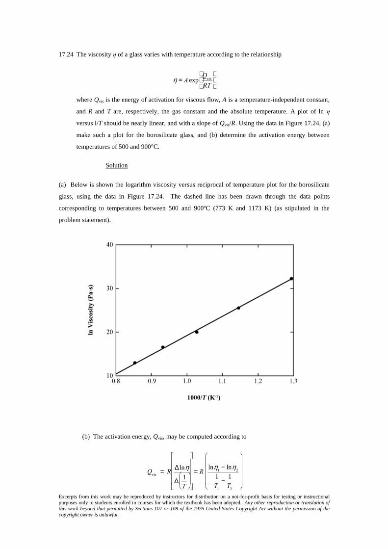
(a) Below is shown the logarithm viscosity versus reciprocal of temperature plot for the borosilicate
glass, using the data in Figure 17.24. The dashed line has been drawn through the data points
corresponding to temperatures between 500 and 900ºC (773 K and 1173 K) (as stipulated in the
problem statement).
(b) The activation energy, Qvis, may be computed according to
Qvis
= RD lnh
D1
T
æ
èç
ö
ø÷
é
ë
êêêê
ù
û
úúúú
= Rlnh
1- lnh
2
1
T1
-1
T2
æ
è
çççç
ö
ø
÷÷÷÷
Excerpts from this work may be reproduced by instructors for distribution on a not-for-profit basis for testing or instructional purposes only to students enrolled in courses for which the textbook has been adopted. Any other reproduction or translation of
this work beyond that permitted by Sections 107 or 108 of the 1976 United States Copyright Act without the permission of the
copyright owner is unlawful.
where R is the gas constant, and D lnh
D1
T
æ
èç
ö
ø÷
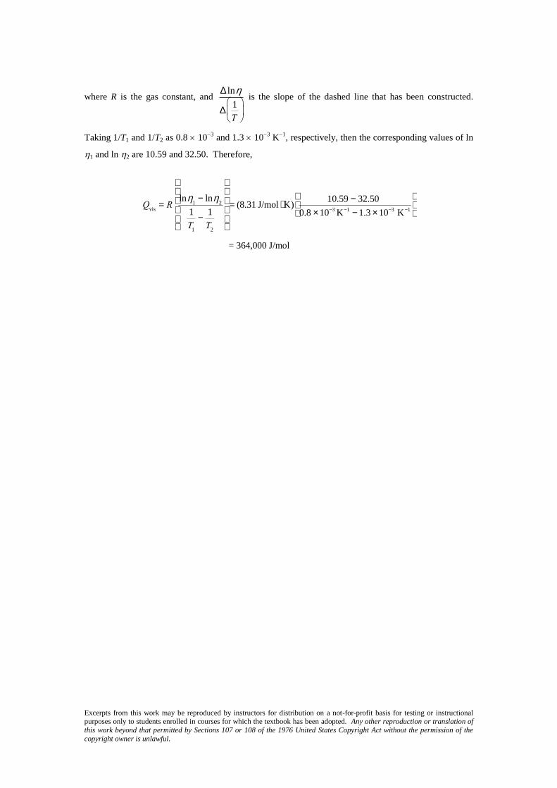
is the slope of the dashed line that has been constructed.
Taking 1/T1 and 1/T2 as 0.8 103
and 1.3 103
K1
, respectively, then the corresponding values of ln
1 and ln 2 are 10.59 and 32.50. Therefore,
Qvis
= Rlnh
1- lnh
2
1
T1
-1
T2
æ
è
çççç
ö
ø
÷÷÷÷
= (8.31 J/mol × K)10.59 - 32.50
0.8 ´ 10-3 K-1 - 1.3 ´ 10-3 K-1
æ
èç
ö
ø÷
= 364,000 J/mol
Excerpts from this work may be reproduced by instructors for distribution on a not-for-profit basis for testing or instructional purposes only to students enrolled in courses for which the textbook has been adopted. Any other reproduction or translation of
this work beyond that permitted by Sections 107 or 108 of the 1976 United States Copyright Act without the permission of the
copyright owner is unlawful.
17.25 For many viscous materials, the viscosity η may be defined in terms of the expression
where σ and de/dt are, respectively, the tensile stress and the strain rate. A cylindrical specimen
of a soda–lime glass of diameter 5 mm and length 100 mm is subjected to a tensile force of 1 N
along its axis. If its deformation is to be less than 1 mm over a week’s time, using Figure 17.24,
determine the maximum temperature to which the specimen may be heated.
Solution
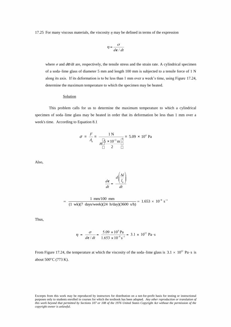
This problem calls for us to determine the maximum temperature to which a cylindrical
specimen of soda–lime glass may be heated in order that its deformation be less than 1 mm over a
week's time. According to Equation 8.1
s = F
A0
= 1 N
p5 ´ 10-3 m
2
æ
èç
ö
ø÷
2= 5.09 ´ 104 Pa
Also,
8 11 mm/100 mm 1.653 10 s(1 wk)(7 days/week)(24 h/day)(3600 s/h)
Thus,
From Figure 17.24, the temperature at which the viscosity of the soda–lime glass is 123.1 10 Pa s is
about 500C (773 K).

Excerpts from this work may be reproduced by instructors for distribution on a not-for-profit basis for testing or instructional purposes only to students enrolled in courses for which the textbook has been adopted. Any other reproduction or translation of
this work beyond that permitted by Sections 107 or 108 of the 1976 United States Copyright Act without the permission of the
copyright owner is unlawful.
17.26 (a) Explain why residual thermal stresses are introduced into a glass piece when it is cooled.
(b) Are thermal stresses introduced upon heating? Why or why not?
Solution
(a) Residual thermal stresses are introduced into a glass piece when it is cooled because surface and
interior regions cool at different rates, and, therefore, contract different amounts; since the material will
experience very little, if any deformation, stresses are established.
(b) Yes, thermal stresses will be introduced because of thermal expansion upon heating for the same
reason as for thermal contraction upon cooling.
Excerpts from this work may be reproduced by instructors for distribution on a not-for-profit basis for testing or instructional purposes only to students enrolled in courses for which the textbook has been adopted. Any other reproduction or translation of
this work beyond that permitted by Sections 107 or 108 of the 1976 United States Copyright Act without the permission of the
copyright owner is unlawful.
17.27 Borosilicate glasses and fused silica are resistant to thermal shock. Why is this so?
Solution
Borosilicate glasses and fused silica are resistant to thermal shock because they have relatively
low coefficients of thermal expansion; therefore, upon heating or cooling, the difference in the degree
of expansion or contraction across a cross-section of a ware that is constructed from these materials
will be relatively low.

Excerpts from this work may be reproduced by instructors for distribution on a not-for-profit basis for testing or instructional purposes only to students enrolled in courses for which the textbook has been adopted. Any other reproduction or translation of
this work beyond that permitted by Sections 107 or 108 of the 1976 United States Copyright Act without the permission of the
copyright owner is unlawful.
17.28 In your own words, briefly describe what happens as a glass piece is thermally tempered.
Thermal tempering of glasses is described in Section 17.8.

Excerpts from this work may be reproduced by instructors for distribution on a not-for-profit basis for testing or instructional purposes only to students enrolled in courses for which the textbook has been adopted. Any other reproduction or translation of
this work beyond that permitted by Sections 107 or 108 of the 1976 United States Copyright Act without the permission of the
copyright owner is unlawful.
17.29 Glass pieces may also be strengthened by chemical tempering. With this procedure, the glass
surface is put in a state of compression by exchanging some of the cations near the surface with
other cations having a larger diameter. Suggest one type of cation that, by replacing Na+, will
induce chemical tempering in a soda–lime glass.
Solution
Chemical tempering will be accomplished by substitution, for Na+, another monovalent cation
with a slightly larger diameter. From Table 4.4, both K+ and Cs
+ fill these criteria, having ionic radii of
0.138 and 0.170 nm, respectively, which are larger than the ionic radius of Na+ (0.102 nm). In fact,
soda–lime glasses are tempered by a K+–Na
+ ion exchange.

Excerpts from this work may be reproduced by instructors for distribution on a not-for-profit basis for testing or instructional purposes only to students enrolled in courses for which the textbook has been adopted. Any other reproduction or translation of
this work beyond that permitted by Sections 107 or 108 of the 1976 United States Copyright Act without the permission of the
copyright owner is unlawful.
Fabrication and Processing of Clay Products
17.30 Cite the two desirable characteristics of clay minerals relative to fabrication processes.
Solution
Two desirable characteristics of clay minerals relative to fabrication processes are (1) they
become hydroplastic (and therefore formable) when mixed with water; and (2) during firing, clays melt
over a range of temperatures, which allows some fusion and bonding of the ware without complete
melting and a loss of mechanical integrity and shape.
Excerpts from this work may be reproduced by instructors for distribution on a not-for-profit basis for testing or instructional purposes only to students enrolled in courses for which the textbook has been adopted. Any other reproduction or translation of
this work beyond that permitted by Sections 107 or 108 of the 1976 United States Copyright Act without the permission of the
copyright owner is unlawful.
17.31 From a molecular perspective, briefly explain the mechanism by which clay minerals become
hydroplastic when water is added.
Solution
Clays become hydroplastic when water is added because the water molecules occupy regions
between the layered molecular sheets; these water molecules essentially eliminate the secondary
molecular bonds between adjacent sheets, and also form a thin film around the clay particles. The net
result is that the clay particles are relatively free to move past one another, which is manifested as the
hydroplasticity phenomenon.

Excerpts from this work may be reproduced by instructors for distribution on a not-for-profit basis for testing or instructional purposes only to students enrolled in courses for which the textbook has been adopted. Any other reproduction or translation of
this work beyond that permitted by Sections 107 or 108 of the 1976 United States Copyright Act without the permission of the
copyright owner is unlawful.
17.32 (a) What are the three main components of a whiteware ceramic such as porcelain?
(b) What role does each component play in the forming and firing procedures?
Solution
(a) The three components of a whiteware ceramic are clay, quartz, and a flux.
(b) With regard to the role that each component plays:
Quartz acts as a filler material.
Clay facilitates the forming operation since, when mixed with water, the mass may be made to
become either hydroplastic or form a slip. Also, since clays melt over a range of
temperatures, the shape of the piece being fired will be maintained.
The flux facilitates the formation of a glass having a relatively low melting temperature.
Excerpts from this work may be reproduced by instructors for distribution on a not-for-profit basis for testing or instructional purposes only to students enrolled in courses for which the textbook has been adopted. Any other reproduction or translation of
this work beyond that permitted by Sections 107 or 108 of the 1976 United States Copyright Act without the permission of the
copyright owner is unlawful.
17.33 (a) Why is it so important to control the rate of drying of a ceramic body that has been
hydroplastically formed or slip cast?
(b) Cite three factors that influence the rate of drying, and explain how each affects the rate.
Solution
(a) It is important to control the rate of drying inasmuch as if the rate of drying is too rapid, there will
be nonuniform shrinkage between surface and interior regions, such that warping and/or cracking of the
ceramic ware may result.
(b) Three factors that affect the rate of drying are temperature, humidity, and rate of air flow. The rate
of drying is enhanced by increasing both the temperature and rate of air flow, and by decreasing the
humidity of the air.

Excerpts from this work may be reproduced by instructors for distribution on a not-for-profit basis for testing or instructional purposes only to students enrolled in courses for which the textbook has been adopted. Any other reproduction or translation of
this work beyond that permitted by Sections 107 or 108 of the 1976 United States Copyright Act without the permission of the
copyright owner is unlawful.
17.34 Cite one reason why drying shrinkage is greater for slip cast or hydroplastic products that have
smaller clay particles.
Solution
The reason that drying shrinkage is greater for products having smaller clay particles is
because there is more particle surface area, and, consequently, more water will surround a given
volume of particles. The drying shrinkage will thus be greater as this water is removed, and as the
interparticle separation decreases.

Excerpts from this work may be reproduced by instructors for distribution on a not-for-profit basis for testing or instructional purposes only to students enrolled in courses for which the textbook has been adopted. Any other reproduction or translation of
this work beyond that permitted by Sections 107 or 108 of the 1976 United States Copyright Act without the permission of the
copyright owner is unlawful.
17.35 (a) Name three factors that influence the degree to which vitrification occurs in clay-based
ceramic wares.
(b) Explain how density, firing distortion, strength, corrosion resistance, and thermal
conductivity are affected by the extent of vitrification.
Solution
(a) Three factors that influence the degree to which vitrification occurs in clay-based ceramic wares
are: (1) composition (especially the concentration of flux present); (2) the temperature of firing; and
(3) the time at the firing temperature.
(b) Density will increase with degree of vitrification since the total remaining pore volume decreases.
Firing distortion will increase with degree of vitrification since more liquid phase will be present at the
firing temperature.
Strength will also increase with degree of vitrification inasmuch as more of the liquid phase forms,
which fills in a greater fraction of pore volume. Upon cooling, the liquid forms a glass matrix of
relatively high strength.
Corrosion resistance normally increases also, especially at service temperatures below that at which the
glass phase begins to soften. The rate of corrosion is dependent on the amount of surface area exposed
to the corrosive medium; hence, decreasing the total surface area by filling in some of the surface
pores, diminishes the corrosion rate.
Thermal conductivity will increase with degree of vitrification. The glass phase has a higher
conductivity than the pores that it has filled.
Excerpts from this work may be reproduced by instructors for distribution on a not-for-profit basis for testing or instructional purposes only to students enrolled in courses for which the textbook has been adopted. Any other reproduction or translation of
this work beyond that permitted by Sections 107 or 108 of the 1976 United States Copyright Act without the permission of the
copyright owner is unlawful.
Powder Pressing
17.36 Some ceramic materials are fabricated by hot isostatic pressing. Cite some of the limitations and
difficulties associated with this technique.
Solution
The principal disadvantage of hot-isostatic pressing is that it is expensive. The pressure is
applied on a pre-formed green piece by a gas. Thus, the process is slow, and the equipment required to
supply the gas and withstand the elevated temperature and pressure is costly.
Excerpts from this work may be reproduced by instructors for distribution on a not-for-profit basis for testing or instructional purposes only to students enrolled in courses for which the textbook has been adopted. Any other reproduction or translation of
this work beyond that permitted by Sections 107 or 108 of the 1976 United States Copyright Act without the permission of the
copyright owner is unlawful.
Polymerization
17.37 Cite the primary differences between addition and condensation polymerization techniques.
Solution
For addition polymerization, the reactant species have the same chemical composition as the
monomer species in the molecular chain. This is not the case for condensation polymerization, wherein
there is a chemical reaction between two or more monomer species, producing the repeating unit.
There is often a low molecular weight by-product for condensation polymerization; such is not found
for addition polymerization.

Excerpts from this work may be reproduced by instructors for distribution on a not-for-profit basis for testing or instructional purposes only to students enrolled in courses for which the textbook has been adopted. Any other reproduction or translation of
this work beyond that permitted by Sections 107 or 108 of the 1976 United States Copyright Act without the permission of the
copyright owner is unlawful.
17.38 (a) How much ethylene glycol must be added to 47.5 kg of dimethyl terephthalate to produce
a linear chain structure of poly(ethylene terephthalate) according to Equation 17.5?
(b) What is the mass of the resulting polymer?
Solution
(a) This problem asks that we determine how much ethylene glycol must be added to 47.5 kg of
dimethyl terephthalate to produce a linear chain structure of poly(ethylene terephthalate) according to
Equation 17.5. Since the chemical formulas are provided in this equation we may calculate the
molecular weights of each of these materials as follows:
MW(ethylene glycol) = 2( AC) + 6( AH) + 2( AO)
= 2(12.01 g/mol) + 6(1.008 g/mol) + 2(16.00 g/mol) = 62.07 g/mol
MW(dimethyl terephthalate) = 10(AC) + 10(AH) + 4(AO)
= 10 (12.01 g/mol) + 10 (1.008 g/mol) + 4(16.00 g/mol) = 194.18 g/mol
The 47.5 kg mass of terephthalic acid equals 47,500 g or 47,500 g
194.18 g/mol = 244.62 mol. Since,
according to Equation 17.5, each mole of dimethyl terephthalate used requires one mole of ethylene
glycol, which is equivalent to (244.62 mol)(62.07 g/mol) = 15,183 g = 15.183 kg.
(b) Now we are asked for the mass of the resulting polymer. Inasmuch as two moles of methanol are
given off for every repeat unit produced, this corresponds to 2*244.62 moles or (489.24 mol)(18.02
g/mol) = 15,675 g or 15.675 kg since the molecular weight of methanol is 32.04 g/mol. The mass of
poly(ethylene terephthalate) is just the sum of the masses of the two reactant materials [as computed in
part (a)] minus the mass of methanol released, or
mass[poly(ethylene terephthalate)] = 47.500 kg + 15.183 kg – 15.676 kg = 47.008 kg
Excerpts from this work may be reproduced by instructors for distribution on a not-for-profit basis for testing or instructional purposes only to students enrolled in courses for which the textbook has been adopted. Any other reproduction or translation of
this work beyond that permitted by Sections 107 or 108 of the 1976 United States Copyright Act without the permission of the
copyright owner is unlawful.
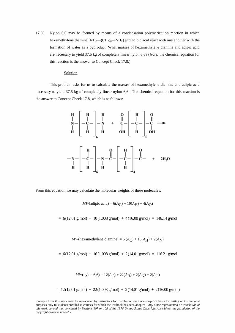
17.39 Nylon 6,6 may be formed by means of a condensation polymerization reaction in which
hexamethylene diamine [NH2—(CH2)6—NH2] and adipic acid react with one another with the
formation of water as a byproduct. What masses of hexamethylene diamine and adipic acid
are necessary to yield 37.5 kg of completely linear nylon 6,6? (Note: the chemical equation for
this reaction is the answer to Concept Check 17.8.)
Solution
This problem asks for us to calculate the masses of hexamethylene diamine and adipic acid
necessary to yield 37.5 kg of completely linear nylon 6,6. The chemical equation for this reaction is
the answer to Concept Check 17.8, which is as follows:
From this equation we may calculate the molecular weights of these molecules.
MW(adipic acid) = 6(AC) + 10(AH) + 4(AO)
= 6(12.01 g/mol) + 10(1.008 g/mol) + 4(16.00 g/mol) = 146.14 g/mol
MW(hexamethylene diamine) = 6 (AC) + 16(AH) + 2(AN)
= 6(12.01 g/mol) + 16(1.008 g/mol) + 2(14.01 g/mol) = 116.21 g/mol
MW(nylon 6,6) = 12(AC) + 22(AH) + 2(AN) + 2(AO)
= 12(12.01 g/mol) + 22(1.008 g/mol) + 2(14.01 g/mol) + 2(16.00 g/mol)

Excerpts from this work may be reproduced by instructors for distribution on a not-for-profit basis for testing or instructional purposes only to students enrolled in courses for which the textbook has been adopted. Any other reproduction or translation of
this work beyond that permitted by Sections 107 or 108 of the 1976 United States Copyright Act without the permission of the
copyright owner is unlawful.
= 226.32 g/mol
The mass of 37.5 kg of nylon 6,6 equals 37,500 g or
m(nylon) = 37,500 g
226.32 g /mol= 165.7 mol
Since, according to the chemical equation given above, each mole of nylon 6,6 repeat units that is
produced requires one mole each of adipic acid and hexamethylene diamine, with two moles of water
as the by-product. The masses corresponding to 165.7 moles of adipic acid and hexamethylene
diamine are as follows:
m(adipic acid) = (165.7 mol)(146.14 g/mol) = 24,215 g = 24.215 kg
m(hexamethylene diamine) = (165.7 mol)(116.21 g/mol) = 19,256 g = 19.256 kg

Excerpts from this work may be reproduced by instructors for distribution on a not-for-profit basis for testing or instructional purposes only to students enrolled in courses for which the textbook has been adopted. Any other reproduction or translation of
this work beyond that permitted by Sections 107 or 108 of the 1976 United States Copyright Act without the permission of the
copyright owner is unlawful.
Polymer Additives
17.40 What is the distinction between dye and pigment colorants?
Solution
The distinction between dye and pigment colorants is that a dye dissolves within and becomes
a part of the polymer structure, whereas a pigment does not dissolve, but remains as a separate phase.

Excerpts from this work may be reproduced by instructors for distribution on a not-for-profit basis for testing or instructional purposes only to students enrolled in courses for which the textbook has been adopted. Any other reproduction or translation of
this work beyond that permitted by Sections 107 or 108 of the 1976 United States Copyright Act without the permission of the
copyright owner is unlawful.
Forming Techniques for Plastics
17.41 Cite four factors that determine what fabrication technique is used to form polymeric
materials.
Solution
Four factors that determine what fabrication technique is used to form polymeric materials
are: (1) whether the polymer is thermoplastic or thermosetting; (2) if thermoplastic, the softening
temperature; (3) atmospheric stability; and (4) the geometry and size of the finished product.

Excerpts from this work may be reproduced by instructors for distribution on a not-for-profit basis for testing or instructional purposes only to students enrolled in courses for which the textbook has been adopted. Any other reproduction or translation of
this work beyond that permitted by Sections 107 or 108 of the 1976 United States Copyright Act without the permission of the
copyright owner is unlawful.
17.42 Contrast compression, injection, and transfer molding techniques that are used to form plastic
materials.
Solution
This question requests that we compare polymer molding techniques. For compression
molding, both heat and pressure are applied after the polymer and necessary additives are situated
between the mold members. For injection molding (normally used for thermoplastic materials), the
raw materials are impelled by a ram through a heating chamber, and finally into the die cavity. For
transfer molding, the solid materials (normally thermosetting in nature) are first melted in the transfer
chamber prior to being forced into the die.

Excerpts from this work may be reproduced by instructors for distribution on a not-for-profit basis for testing or instructional purposes only to students enrolled in courses for which the textbook has been adopted. Any other reproduction or translation of
this work beyond that permitted by Sections 107 or 108 of the 1976 United States Copyright Act without the permission of the
copyright owner is unlawful.
Fabrication of Fibers and Films
17.43 Why must fiber materials that are melt-spun and then drawn be thermoplastic? Cite two
reasons.
Solution
Fiber materials that are melt spun must be thermoplastic because: (1) In order to be melt-spun,
they must be capable of forming a viscous liquid when heated, which is not possible for thermosets.
(2) During drawing, mechanical elongation must be possible; inasmuch as thermosetting materials are,
in general, hard and relatively brittle, they are not easily elongated.
Excerpts from this work may be reproduced by instructors for distribution on a not-for-profit basis for testing or instructional purposes only to students enrolled in courses for which the textbook has been adopted. Any other reproduction or translation of
this work beyond that permitted by Sections 107 or 108 of the 1976 United States Copyright Act without the permission of the
copyright owner is unlawful.
17.44 Which of the following polyethylene thin films would have the better mechanical
characteristics: (1) formed by blowing, or (2) formed by extrusion and then rolled? Why?
Solution
Of the two polymers cited, the one that was formed by extrusion and then rolled would have
the higher strength. Both blown and extruded materials would have roughly comparable strengths;
however the rolling operation would further serve to enhance the strength of the extruded material.

Excerpts from this work may be reproduced by instructors for distribution on a not-for-profit basis for testing or instructional purposes only to students enrolled in courses for which the textbook has been adopted. Any other reproduction or translation of
this work beyond that permitted by Sections 107 or 108 of the 1976 United States Copyright Act without the permission of the
copyright owner is unlawful.
DESIGN PROBLEMS
Heat Treatment of Steels
17.D1 A cylindrical piece of steel 20 mm in diameter is to be quenched in moderately agitated oil.
Surface and center hardnesses must be at least 55 and 50 HRC, respectively. Which of the
following alloys will satisfy these requirements: 1040, 5140, 4340, 4140, and 8640? Justify
your choice(s).
Solution
In moderately agitated oil, the equivalent distances from the quenched end for a 20-mm
diameter bar for surface and center positions are 3 mm and 8 mm respectively [Figure 17.11b]. The
hardnesses at these two positions for the alloys cited (as determined using Figure 17.8) are given
below.
Surface Center
Alloy Hardness (HRC) Hardness (HRC)
1040 50 30
5140 56 49
4340 57 57
4140 57 55
8640 57 53
Thus, alloys 4340, 4140, and 8640 will satisfy the criteria for both surface and center
hardnesses.

Excerpts from this work may be reproduced by instructors for distribution on a not-for-profit basis for testing or instructional purposes only to students enrolled in courses for which the textbook has been adopted. Any other reproduction or translation of
this work beyond that permitted by Sections 107 or 108 of the 1976 United States Copyright Act without the permission of the
copyright owner is unlawful.
17.D2 A cylindrical piece of steel 70 mm in diameter is to be austenitized and quenched such that a
minimum hardness of 40 HRC is to be produced throughout the entire piece. Of the alloys 8660,
8640, 8630, and 8620, which will qualify if the quenching medium is (a) moderately agitated
water, and (b) moderately agitated oil? Justify your choice(s).
Solution
(a) This problem calls for us to decide which of 8660, 8640, 8630, and 8620 alloys may be fabricated
into a cylindrical piece 70 mm in diameter which, when quenched in mildly agitated water, will
produce a minimum hardness of 40 HRC throughout the entire piece.
The center of the steel cylinder will cool the slowest and therefore will be the softest. In
moderately agitated water the equivalent distance from the quenched end for a 70-mm diameter bar for
the center position is about 15 mm [Figure 17.11a]. The hardnesses at this position for the alloys cited
(Figure 17.9) are given below.
Center
Alloy Hardness (HRC)
8660 58
8640 42
8630 30
8620 22
Therefore, only 8660 and 8640 alloys will have a minimum of 40 HRC at the center, and therefore,
throughout the entire cylinder.
(b) This part of the problem asks us to do the same thing for moderately agitated oil. In moderately
agitated oil the equivalent distance from the quenched end for a 70-mm diameter bar at the center
position is about 22.5 mm [Figure 17.11b]. The hardnesses at this position for the alloys cited (Figure
17.9) are given below.
Center
Alloy Hardness (HRC)
8660 53
8640 37
8630 26
8620 < 20
Therefore, only the 8660 alloy will have a minimum of 40 HRC at the center, and therefore, throughout
the entire cylinder.

Excerpts from this work may be reproduced by instructors for distribution on a not-for-profit basis for testing or instructional purposes only to students enrolled in courses for which the textbook has been adopted. Any other reproduction or translation of
this work beyond that permitted by Sections 107 or 108 of the 1976 United States Copyright Act without the permission of the
copyright owner is unlawful.
17.D3 A cylindrical piece of steel 40 mm in diameter is to be austenitized and quenched such that a
microstructure consisting of at least 80% martensite will be produced throughout the entire
piece. Of the alloys 4340, 4140, 8640, 5140, and 1040, which will qualify if the quenching
medium is (a) moderately agitated oil and (b) moderately agitated water? Justify your choice(s).
Solution
(a) Since the cooling rate is lowest at the center, we want a minimum of 80% martensite at the center
position. From Figure 17.11b, the cooling rate is equal to an equivalent distance from the quenched
end of 12 mm. According to Figure 17.8, the hardness corresponding to 80% martensite for these
alloys is 50 HRC. Thus, all we need do is to determine which of the alloys have a 50 HRC hardness at
an equivalent distance from the quenched end of 8 mm. At an equivalent distance of 8 mm, the
following hardnesses are determined from Figure 17.8 for the various alloys.
Alloy Hardness (HRC)
4340 56
4140 53
8640 49
5140 43
1040 25
Thus, only alloys 4340 and 4140 will qualify.
(b) For moderately agitated water, the cooling rate at the center of a 40-mm diameter specimen is 8 mm
equivalent distance from the quenched end [Figure 17.11a]. At this position, the following hardnesses
are determined from Figure 17.8 for the several alloys.
Alloy Hardness (HRC)
4340 57
4140 55
8640 54
5140 51
1040 33
It is still necessary to have a hardness of 50 HRC or greater at the center; thus, alloys 4340, 4140, 8640,
and 5140 qualify.
Excerpts from this work may be reproduced by instructors for distribution on a not-for-profit basis for testing or instructional purposes only to students enrolled in courses for which the textbook has been adopted. Any other reproduction or translation of
this work beyond that permitted by Sections 107 or 108 of the 1976 United States Copyright Act without the permission of the
copyright owner is unlawful.
17.D4 A cylindrical piece of steel 85 mm in diameter is to be quenched in moderately agitated water.
Surface and center hardnesses must be at least 55 and 40 HRC, respectively. Which of the
following alloys will satisfy these requirements: 1040, 5140, 4340, 4140, 8620, 8630, 8640, and
8660? Justify your choices.
Solution
An 85-mm diameter cylindrical steel specimen is to be quenched in moderately agitated water.
We are to decide which of eight different steels will have surface and center hardnesses of at least 55
and 40 HRC, respectively.
In moderately agitated water, the equivalent distances from the quenched end for an 85-mm
diameter bar for surface and center positions are 3 mm and 20 mm, respectively [Figure 17.11a]. The
hardnesses at these two positions for the alloys cited are given below (as determined from Figures 17.8
and 17.9).
Surface Center
Alloy Hardness (HRC) Hardness (HRC)
1040 50 < 20
5140 56 34
4340 57 53
4140 57 45
8620 42 < 20
8630 51 28
8640 56 38
8660 64 55
Thus, alloys 4340, 4140, and 8660 will satisfy the criteria for both surface hardness (minimum 55
HRC) and center hardness (minimum 40 HRC).

Excerpts from this work may be reproduced by instructors for distribution on a not-for-profit basis for testing or instructional purposes only to students enrolled in courses for which the textbook has been adopted. Any other reproduction or translation of
this work beyond that permitted by Sections 107 or 108 of the 1976 United States Copyright Act without the permission of the
copyright owner is unlawful.
17.D5 A cylindrical piece of 4140 steel is to be austenitized and quenched in moderately agitated oil.
If the microstructure is to consist of at least 50% martensite throughout the entire piece, what
is the maximum allowable diameter? Justify your answer.
Solution
From Figure 17.8, the equivalent distance from the quenched end of a 4140 steel to give 50%
martensite (or a 42.5 HRC hardness) is 27 mm. Thus, the quenching rate at the center of the specimen
should correspond to this equivalent distance. Using Figure 17.11b, the center specimen curve takes on
a value of 27 mm equivalent distance at a diameter of about 83 mm.
Excerpts from this work may be reproduced by instructors for distribution on a not-for-profit basis for testing or instructional purposes only to students enrolled in courses for which the textbook has been adopted. Any other reproduction or translation of
this work beyond that permitted by Sections 107 or 108 of the 1976 United States Copyright Act without the permission of the
copyright owner is unlawful.
17.D6 A cylindrical piece of 8640 steel is to be austenitized and quenched in moderately agitated oil.
If the hardness at the surface of the piece must be at least 49 HRC, what is the maximum
allowable diameter? Justify your answer.
Solution
We are to determine, for a cylindrical piece of 8640 steel, the minimum allowable diameter
possible in order yield a surface hardness of 49 HRC, when the quenching is carried out in moderately
agitated oil.
From Figure 17.9, the equivalent distance from the quenched end of an 8640 steel to give a
hardness of 49 HRC is about 12 mm. Thus, the quenching rate at the surface of the specimen should
correspond to this equivalent distance. Using Figure 17.11b, the surface specimen curve takes on a
value of 12 mm equivalent distance at a diameter of about 75 mm.

Excerpts from this work may be reproduced by instructors for distribution on a not-for-profit basis for testing or instructional purposes only to students enrolled in courses for which the textbook has been adopted. Any other reproduction or translation of
this work beyond that permitted by Sections 107 or 108 of the 1976 United States Copyright Act without the permission of the
copyright owner is unlawful.
17.D7 Is it possible to temper an oil-quenched 4140 steel cylindrical shaft 100 mm in diameter so as
to give a minimum tensile strength of 850 MPa and a minimum ductility of 21%EL? If so,
specify a tempering temperature. If this is not possible, then explain why.
Solution
This problem asks if it is possible to temper an oil-quenched 4140 steel cylindrical shaft 100
mm in diameter so as to give a minimum tensile strength of 850 MPa and a minimum ductility of
21%EL. In order to solve this problem it is necessary to use Figures 17.14a and 17.14c, which plot,
respectively, tensile strength and ductility versus tempering temperature. For the 100 mm diameter line
of Figure 17.14a, tempering temperatures less than about 560°C (833 K) are required to give a tensile
strength of at least 850 MPa. Furthermore, from Figure 17.14c, for the 100 mm diameter line,
tempering temperatures greater than about 585°C (858 K) will give ductilities greater than 21%EL.
Hence, it is not possible to temper this alloy to produce the stipulated minimum tensile strength and
ductility. To meet the tensile strength minimum, T(tempering) < 560°C (833 K), whereas for ductility
minimum, T(tempering) > 585°C; thus, there is no overlap of these tempering temperature ranges.

Excerpts from this work may be reproduced by instructors for distribution on a not-for-profit basis for testing or instructional purposes only to students enrolled in courses for which the textbook has been adopted. Any other reproduction or translation of
this work beyond that permitted by Sections 107 or 108 of the 1976 United States Copyright Act without the permission of the
copyright owner is unlawful.
17.D8 Is it possible to temper an oil-quenched 4140 steel cylindrical shaft 13 mm in diameter so as to
give a minimum yield strength of 1000 MPa and a minimum ductility of 16%EL? If so,
specify a tempering temperature. If this is not possible, then explain why.
Solution
This problem asks if it is possible to temper an oil-quenched 4140 steel cylindrical shaft 13
mm in diameter so as to give a minimum yield strength of 1000 MPa and a minimum ductility of
16%EL. In order to solve this problem it is necessary to use Figures 17.14b and 17.14c, which plot,
respectively, yield strength and ductility versus tempering temperature. For the 13-mm diameter line of
Figure 17.14b, tempering temperatures less than about 600°C (873 K) are required to give a yield
strength of at least 1000 MPa. Furthermore, from Figure 17.14c, for the 13 mm diameter line,
tempering temperatures greater than about 550°C (823 K) will give ductilities greater than 17%EL.
Hence, it is possible to temper this alloy to produce the stipulated minimum yield strength and
ductility; the tempering temperature will lie between 823 K and 873 K.
Excerpts from this work may be reproduced by instructors for distribution on a not-for-profit basis for testing or instructional purposes only to students enrolled in courses for which the textbook has been adopted. Any other reproduction or translation of
this work beyond that permitted by Sections 107 or 108 of the 1976 United States Copyright Act without the permission of the
copyright owner is unlawful.
Precipitation Hardening
17.D9 Copper-rich copper–beryllium alloys are precipitation hardenable. After consulting the portion
of the phase diagram (Figure 17.43), do the following:
(a) Specify the range of compositions over which these alloys may be precipitation hardened.
(b) Briefly describe the heat-treatment procedures (in terms of temperatures) that would be
used to precipitation harden an alloy having a composition of your choosing, yet lying within
the range given for part (a).
Solution
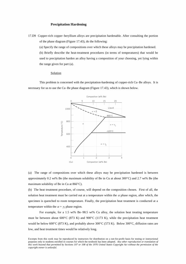
This problem is concerned with the precipitation-hardening of copper-rich Cu–Be alloys. It is
necessary for us to use the Cu–Be phase diagram (Figure 17.43), which is shown below.
(a) The range of compositions over which these alloys may be precipitation hardened is between
approximately 0.2 wt% Be (the maximum solubility of Be in Cu at about 300C) and 2.7 wt% Be (the
maximum solubility of Be in Cu at 866C).
(b) The heat treatment procedure, of course, will depend on the composition chosen. First of all, the
solution heat treatment must be carried out at a temperature within the phase region, after which, the
specimen is quenched to room temperature. Finally, the precipitation heat treatment is conducted at a
temperature within the + 2 phase region.
For example, for a 1.5 wt% Be–98.5 wt% Cu alloy, the solution heat treating temperature
must be between about 600C (873 K) and 900C (1173 K), while the precipitation heat treatment
would be below 600C (873 K), and probably above 300C (573 K). Below 300C, diffusion rates are
low, and heat treatment times would be relatively long.

Excerpts from this work may be reproduced by instructors for distribution on a not-for-profit basis for testing or instructional purposes only to students enrolled in courses for which the textbook has been adopted. Any other reproduction or translation of
this work beyond that permitted by Sections 107 or 108 of the 1976 United States Copyright Act without the permission of the
copyright owner is unlawful.
17.D10 A solution heat-treated 2014 aluminum alloy is to be precipitation hardened to have a
minimum tensile strength of 450 MPa and a ductility of at least 15%EL. Specify a practical
precipitation heat treatment in terms of temperature and time that would give these mechanical
characteristics. Justify your answer.
Solution
We are asked to specify a practical heat treatment for a 2014 aluminum alloy that will produce
a minimum tensile strength of 450 MPa, and a minimum ductility of 15%EL. From Figure 17.21a, the
following heat treating temperatures and time ranges are possible to the give the required tensile
strength.
Temperature (C) Time Range (h)
260 0.02–0.2
204 0.02–10
149 3–600
121 > 35–?
With regard to temperatures and times to give the desired ductility [Figure 17.21b]:
Temperature (C) Time Range (h)
260 < 0.01, > 40
204 < 0.15
149 < 10
121 < 500
From these tabulations, the following may be concluded:
It is not possible to heat treat this alloy at 260C so as to produce the desired set of
properties— there is no overlap of the two sets of time ranges.
At 204C, the heat treating time would be between 0.02 and 0.15 h; times lying within this
range are impractically short.
At 149C, the time would be between 3 and 10 h.
Finally, at 121C, the time range is 35 to about 500 h.

Excerpts from this work may be reproduced by instructors for distribution on a not-for-profit basis for testing or instructional purposes only to students enrolled in courses for which the textbook has been adopted. Any other reproduction or translation of
this work beyond that permitted by Sections 107 or 108 of the 1976 United States Copyright Act without the permission of the
copyright owner is unlawful.
17.D11 Is it possible to produce a precipitation-hardened 2014 aluminum alloy having a minimum
tensile strength of 425 MPa and a ductility of at least 12%EL? If so, specify the precipitation
heat treatment. If it is not possible, explain why.
Solution
This problem inquires as to the possibility of producing a precipitation-hardened 2014
aluminum alloy having a minimum tensile strength of 425 MPa and a ductility of at least 12%EL. In
order to solve this problem it is necessary to consult Figures 17.21a and 17.21b. Below are tabulated
the times required at the various temperatures to achieve the stipulated tensile strength.
Temperature (C) Temperature (K) Time Range (h)
260 533 < 0.5
204 477 < 15
149 422 1–1000
121 394 > 35–?
With regard to temperatures and times to give the desired ductility:
Temperature (C) Temperature (K) Time Range (h)
260 533 < 0.02, > 10
204 477 < 0.4, > 350
149 422 < 20
121 394 < 1000
From these tabulations, the following may be concluded:
At 260C (533 K), the heat treating time would need to be less than 0.02 h (1.2 min), which is
impractically short.
At 204C (477 K), the heat treatment would need to be less than 0.4 h (24 min), which is a
little on the short side.
At 149C (422 K), the time range would be between 1 and 20 h.
Finally, at 121C (394 K), this property combination is possible for virtually all times less
than about 1000 h.